

Page 1
SERIES 552A/553A
COMMERCIAL PUMPS
INSTALLATION/OPERATION/PARTS
MANUAL
035299
REV. 03/07/03
INSTALLERS - IMPORTANT
In addition to installation information, this manual contains warnings, safeguards
and procedures on the use and care o f the Series 550A pumps. Please leave this
manual with the pump owner after the installation is complete.
The information in this document is confidential and proprietary. No further disclosure shall be made without
permission from Gasboy International LLC. Gasboy International LLC believes that the information in this document
is accurate and reliable. However, we assume no responsibility for its use, nor for any infringements of patents or
other rights of third parties resulting from its use. We reserve the right to make changes at any time without notice.
Copyright 2003 by Gasboy International LLC All rights reserved.
GASBOY INTERNATIONAL LLC LANSDALE, PA
Page 2

IMPORTANT WARNINGS AND SAFEGUARDS
Gasoline and petroleum products are flammable. To avoid injury or death to persons or damage to equipment or
property, follow these listed warnings and other warnings and precautions outlined in this manual when installing, using,
or working around this equipment. Check with GASBOY Technical Services for compatibility of liquids with pump
materials.
TURN OFF AND LOCK OUT ALL POWER TO PUMP BEFORE PERFORMING SERVICE, MAINTENANCE OR IN THE EVENT
All products must be installed by a
qualified installer and used in
conformance with all building, fire, and
environmental codes and other safety
requirements applicable to its
installation and use, including, but not
limited to, NFPA 30, NFPA 30A, NFPA
395 & NFPA 70. A qualified installer is
familiar with fuel systems installations
under the above stated building, fire,
and environmental codes and other
safety requirements for the particular
type of installation.
This product is only part of a fuel
dispensing system and additional
equipment and accessories, such as,
but not limited to, breakaway
connectors, shear valves, pressure
regulators, flow limiters, and other
safety devices may be necessary to
meet the applicable codes.
For maximum safety, we recommend
that all employees be trained as to the
location and procedure for turning off
power to th e enti re system. Instru ctions
regarding proper operation of the
equipment along with the appropriate
safety warnings should be posted in
plain view at the fuel island.
Before performing service or
maintenance (including changing of fuel
filters or strainers) or in the event of a
fuel spill, turn off and lock out all power
to the system. In battery-powered
pumps, disconnect power source. In
submersible pump applications, turn off
and lock out power at the master panel
and close any impact valves to the
submersible pump and any other
dispensers which use that submersible
pump. AC power can feed back into a
shut-off dispenser when dispensers
share a common submersible pump or
starter relay. Also block islands so no
vehicles can pull up to the dispenser
when the dispenser is being worked on.
DO NOT use Teflon tape for any pipe
threads in the product.
DO NOT use consumer pumps for
pumping fuel or additives into aircraft.
DO NOT use commercial pumps for
direct fueling of aircraft without filters
and separators necessary to ensure
product purity.
DO NOT use where sanitary design is
required (for food products for human
consumption) or with water-based
liquids.
DO NOT smoke near the pump or when
using the pump.
DO NOT use near open flame or
electrical equipment which may ignite
fumes.
DO NOT permit the dispensing of
gasoline or other petroleum products
into a vehicle with its motor running.
DO NOT permit the dispensing of
gasoline or other petroleum products
into unapproved containers or into
approved containers in or on vehicles
includin g trucks. All contain ers must be
filled on the ground to prevent static
discharge. Always use Approved and
Listed hoses and nozzles with electric
pumps and dispensers.
DO NOT block open the nozzle in any
manner. Nozzles shall conform to UL
and NFPA code requirements for
attended or unattended service.
DO ensure that the pump is equipped
with proper filters based on the product
being dispensed and its intended use.
DO wear safety goggles and protective
clothes when dispensing any liquid
which may be potentially harmful or
hazardous.
DO keep all parts of body and loose
clothing clear of belts, pulleys, and other
exposed moving parts at all times.
OF A FUEL SPILL.
DO require washing and changing of
clothes if fuel is spilled on a person or
his/her clothing. Keep away from open
flames, sparks, or people smoking.
DO provide a receptacle for catching
product from pump/meter when
servicing.
DO clean up product spills on the
driveway. Turn off and lock out all
power prior to cleanup.
DO insure pump is properly grounded.
DO insure hose is compatible with fluid
being dispensed.
DO inspect hose, nozzle, and pump on
a regular basis for wear, damage, or
other conditions which may create a
safety or environmental hazard.
DO make sure all pipe threads are
properly cut and the inside reamed to
remove burrs. Use UL classified
gasoline-resisting compound on all
joints of gasoline handling piping.
Sealing compound must also be
resistant to Gasohol (Ethanol and
Methanol). Use gasoline-resistant pipe
compound on male threads only; pipe
compound used on female threads can
be squeezed into the supply line where
it can enter the product stream and
become lodged in the pump or meter.
DO ensure that junction box covers are
in place and properly tightened. Mating
surfaces between the box and cover
must be free of dirt, nicks, and
scratches. All unused entries into the
junction box must be properly plugged.
035282 Rev. 1267
GASBOY INTERNATIONAL LLC.
707 North Valley Forge Rd. Lansdale, PA, 19446 ● (215) 855-4631 ● FAX: (215) 855-0341
Page 3

CONTENTS
IMPORTANT WARNINGS AND SAFEGUARDS
Section 1: INTRODUCTION
Purpose..................................................................................................... 1-1
Overview ................................................................................................... 1-1
Section 2: INSTALLATION
Before You Begin...................................................................................... 2-1
Installation Precautions............................................................................. 2-1
Foundation ................................................................................................ 2-2
Suction Pump............................................................................................ 2-2
Installation Layout ..................................................................................... 2-3
Supply Line................................................................................................ 2-4
Connecting the Suction Pipe................................................................ 2-4
Base Layout - 011982............................................................................... 2-5
Section 3: WIRING
Wiring Precautions.................................................................................... 3-1
Grounding ................................................................................................. 3-1
Circuit Breakers......................................................................................... 3-2
Pump Motor............................................................................................... 3-2
Wiring and Conduit.................................................................................... 3-2
Pump Wiring......................................................................................... 3-2
Pulser Wiring........................................................................................ 3-3
Conduit................................................................................................. 3-3
Wiring Notes.............................................................................................. 3-4
Wiring Diagram - 024206 .......................................................................... 3-5
Section 4: TESTING AND OPERATION
Testing the Installation .............................................................................. 4-1
Operating Instructions............................................................................... 4-1
Section 5: MAINTENANCE AND TROUBLESHOOTING
General ..................................................................................................... 5-1
Exterior Maintenance ................................................................................ 5-1
Lubricating the Pump’s Components ........................................................ 5-2
Cleaning the Strainer................................................................................. 5-3
Calibrating the Meter................................................................................. 5-3
Correcting Meter Drive Shaft Leak............................................................ 5-3
Adjusting the Belts..................................................................................... 5-4
Troubleshooting......................................................................................... 5-5
Preparing Used Pumps for Storage .......................................................... 5-6
03/07/03 Contents-1
Page 4

GASBOY 552A/553A Commercial Pumps
Section 6: PARTS LIST
General ..................................................................................................... 6-1
Panels and Trim Diagram.......................................................................... 6-2
Panels and Trim Parts............................................................................... 6-3
Chassis Assembly – Front and Rear View Diagram ................................. 6-4
Chassis Assembly – Front and Rear View Parts....................................... 6-5
Adapter Assembly..................................................................................... 6-6
Dial Enclosure Assembly........................................................................... 6-7
Meter Assembly Diagram.......................................................................... 6-8
Meter Assembly Parts............................................................................... 6-9
Meter Assembly Breakdown Diagram....................................................... 6-10
Meter Assembly Breakdown Parts............................................................ 6-11
Motor Assembly Diagram.......................................................................... 6-12
Motor Assembly Parts............................................................................... 6-13
Pumping Unit Assembly Diagram.............................................................. 6-14
Pumping Unit Assembly Parts................................................................... 6-15
Pumping Unit Assembly Breakdown Diagram........................................... 6-16
Pumping Unit Assembly Breakdown Parts................................................ 6-17
Register Assembly With Start-Stop Linkage Diagram............................... 6-18
Register Assembly With Start-Stop Linkage Parts.................................... 6-19
Register Assembly with Interlock Diagram................................................ 6-20
Register Assembly with Interlock Parts..................................................... 6-21
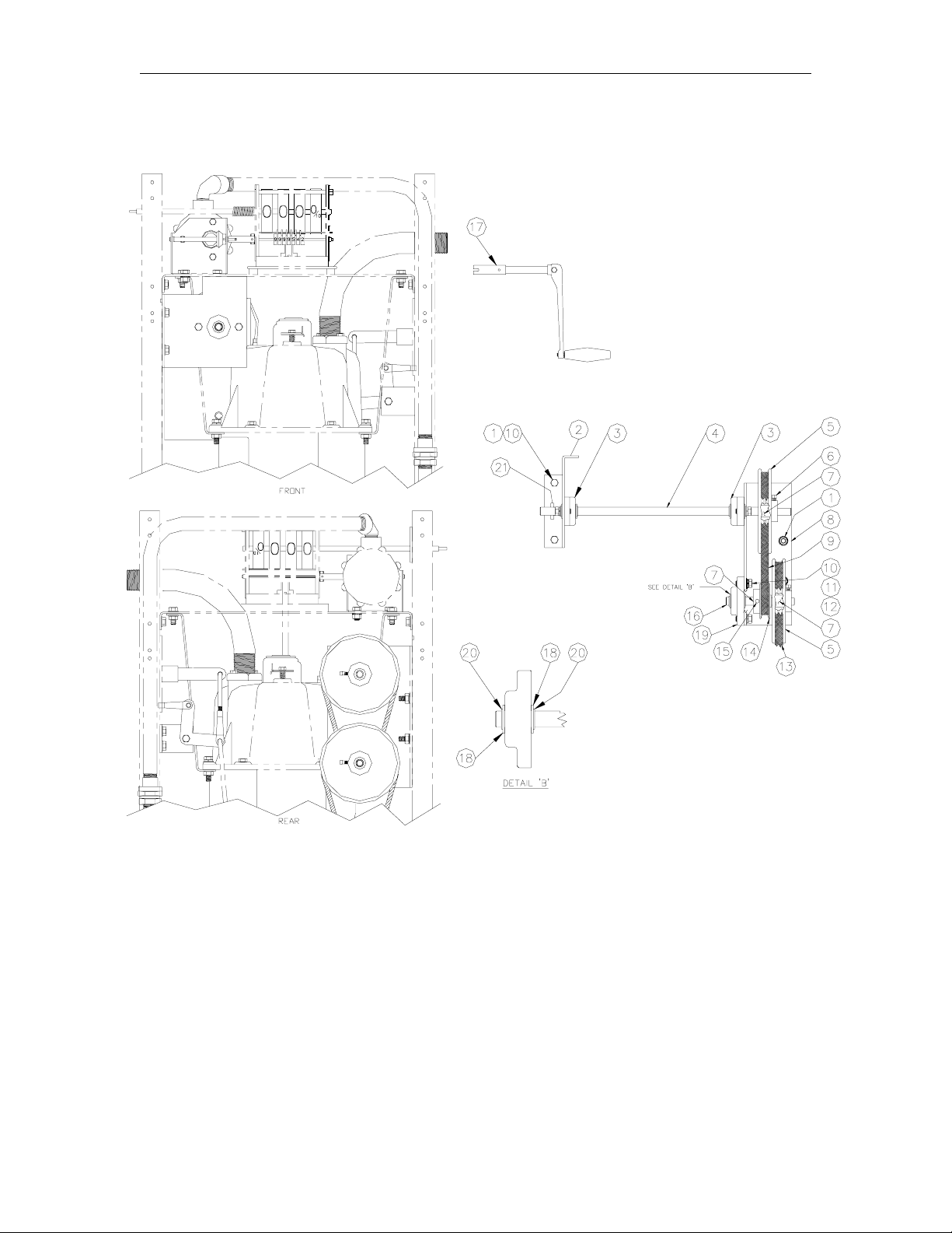
Hand Crank Assembly Diagram................................................................ 6-22
Hand Crank Assembly Parts..................................................................... 6-23
Pulser Assembly Diagram......................................................................... 6-24
Pulser Assembly Parts.............................................................................. 6-25
Accessories and Field Kits........................................................................ 6-26
Contents-2 03/07/03
Page 5

Section 1
INTRODUCTION
PURPOSE
The GASBOY 552A/553A Commer cial Pumps Installation/Operation/Parts Manual is provided to
assist the installer in installing and operating the unit. This manual should be supplied to the
electrician prior to the installation of conduit and wiring to ensure the unit is installed properly.
Faulty installations are the major cause of unit malfunctions. This unit must be installed and
operated as described in the manual to ensure the reliability and proper operation of the 550A
Series pumps. Be sure to leave this manual with the pump owner when the installation is
complete. Customers and installers having any questions pertaining to this installation should
contact their GASBOY distributor.
OVERVIEW
The GASBOY 552A/553A pumps are UL-listed, heavy-duty, suction pumps designed for the
needs of local and state governments, industrial, commercial, and private fleet operations. 550A
Series pumps have the following features:
• Dimensions: Base 13-31/32" (35cm) x 18-1/16" (46cm), height 40-1/8" (102cm)
• Construction: Top and side carbon steel panels; front and back hot-dipped galvanized steel,
for rust resistance.
• Cabinet: painted black with white door or color of your choice
• Motor:
1/2 HP intermittent duty, dual voltage/dual frequency, 115/230VAC, 50/60 Hz (552A);
3/4 HP continuous duty, dual voltage/dual frequency, 115/230 VAC, 50/60 Hz (553AMC);
3/4 HP continuous duty, 380 VAC, 50 Hz (553AMC)
• Pump: Rotary gear pump with air eliminator built into pump casting, positive displacement, no
priming necessary.
• Register: 4-wheel volume only, indicating up to 999.9 gallons/liters
• Totalizer: 999,999.9 gallons/liters
• Reset: manual or manual with interlock for use in retail sales
• Meter: positive displacement, Model 898-K
• Display: single-sided
• Dial Face: white with black text
• Hose: 552A - 3/4" (2cm) x 12 feet (3.6m); 553A - 1" (2.5cm) x 12 feet (3.6m)
• Suction connection: 1-1/2" NPT, unions provided
• Delivery Rate: up to 15 GPM/57 LPM (552A); up to 22 GPM/83 LPM (553A). Delivery rates
are maximum test rates. Actual rates will vary depending upon installation conditions,
product dispensed, and added accessories.
• Nozzle: Must be purchased separately. Automatic nozzles available.
03/07/03 1-1
Page 6

GASBOY 552A/553A Commercial Pumps
Optional accessories include: additional hose lengths, external filter kits, vertical check valve, high
speed hand attachment, Model 52 pressure regulating valve, pulsers, reset interlock, 380VAC/50
Hz. operation, imperial gallon or liter registration.
1-2 03/07/03
Page 7

Section 2
INSTALLATION
BEFORE YOU BEGIN
Before uncrating the pump, inspect the crate for damage. A damaged crate indicates possible
internal damage to the dispenser, and the delivering carrier should be notified of possible
concealed damage. It is recommended the original shipping crate be retained for pump reshipment at some later date.
INSTALLATION PRECAUTIONS
All installations must conform with all building/fire codes, all Federal, State, and Local codes,
National Electrical Code, (NFPA 70), NFPA 30, and Automotive and Marine Service Station Code
(NFPA 30A) codes and regulations.
Plan your installation carefully. A pump cannot be expected to work satisfactorily unless the
underground installation is correct. Dispensing troubles, which seem to be pump-related, are
frequently traced to faulty installation. Review the following list of installation DO’s and DON’T’s
to avoid potential problems:
1. DO read the WARNINGS page at the front of this manual, preceding the Table of Contents.
It contains important information regarding the safe use of your dispensing equipment.
2. DO install an emergency power cutoff. In addition to circuit breaker requirements of NFPA 70
and NFPA 30A, a single control which simultaneously removes AC power from all site
dispensing equipment is recommended. This control must be readily accessible, clearly
labeled, and in accordance with all local codes.
In order to provide the highest level of safety to you, your employees, and customers, we
recommend that all employees be trained as to the location and procedure for turning off
power to the entire system.
3. DO have the pump/dispenser installed by a competent installer/electrician.
4. DO install breakaway coupling on discharge hose. If using a high hose retriever, install
breakaway approximately 12" downstream of hose clamp on nozzle side of clamp.
5. DO NOT experiment with a pump if you are not sure the installation is correct.
6. DO NOT overload sub- or main breaker panels.
7. DO NOT install any underground piping without proper swing joints. (Always use shoulder
nipples, never close nipples).
8. DO NOT cover any lines until they have been both air- and liquid-tested.
9. DO NOT back-fill the tank or supply line with cinders or ashes. (Back-fill with clean sand,
crushed rock, or pea gravel).
10. DO NOT use black iron pipe or fittings for underground installations. (Use only new
galvanized or fiberglass* pipe and fittings). *Install all fiberglass pipe and fittings according to
manufacturer’s specifications and requirements.
03/07/03 2-1
Page 8

GASBOY 552A/553A Commercial Pumps
11. DO NOT use power line wiring of inadequate capacity. (Use gauge specified by the wiring
diagram or wire chart provided in Section 3).
12. DO NOT use a circuit breaker of improper size. (See Section 3).
13. DO NOT install fill pipe to tank where it can be submerged with standing water.
14. DO NOT use the GASBOY fuel dispensing equipment to remove water ballast from the
storage tank.
15. DO NOT use gaskets on covers of explosion-proof type boxes. The sealing compound found
around wires at various locations within conduit is a requirement of the National Electrical
Code and should not be disturbed. Ensure that
free of dirt, nicks, and scratches.
16. DO NOT use knock-out boxes or flexible conduit for installing this unit. All wires should be
run in threaded, rigid, metal conduit. All threaded connections must be drawn up tight with
five (5) threads minimum engagement. Only one opening in the AC junction box is provided
with a plug at the factory. At completion of the installation, it is the installer’s responsibility to
ensure that any unused openings are plugged.
Tighten junction box covers before replacing panels.
mating surfaces between the box and cover are
FOUNDATION
When constructing the pump island for the dispensing equipment, be sure to extend the island
excavation beyond the depth of the frost line. Leave open an area from the inside edge of the
unit’s base as shown on the specific base layout. Unless required by local regulations, do not
cement the pipes and conduits into the island. The open area within the base will provide access
for future servicing of the fittings and conduit assemblies. Fill in the boxed-in section with dry sand
to keep condensation in the pump housing to a minimum and to help prevent fogging of the
totalizer window.
Secure the pump/dispenser to the island using anchor bolts through the two mounting holes,
which are indicated on each base layout by an X. If the dispensing unit is not securely fastened to
the island, supply line leaks at unions and pipe joints may occur. Use one of two types of bolts to
anchor the pump to the island. Use two (2) 1/2" x 5" (13mm x 125mm) long machine bolts
imbedded in the concrete, or, to meet minimum UL and API requirements for universal
interchangeability of pumps, use two 1/2" x 3 1/2" (13mm x 90mm) long lag screws with 2" (51mm)
long expansion shields.
The drawing on the following page, Installation Layout, illustrates a recommended installation of
the Model 552A & 553A power pump. In selecting a location for the pump and tank, bear in mind
that a suction pump will draw liquid horizontally up to 100 feet, but on a vertical lift it is not
advisable to exceed 12 feet (3.6m) for gasoline, or 13 feet (4m) for diesel.
SUCTION PUMP
The pump and the tank should be located close to each other with as few changes in direction of
the supply line, as possible. This reduces the possibility of vaporization (gasoline only), attains the
highest possible flow rate, and results in a lower installation cost. Avoid long supply lines and
excessive vertical lifts. The dynamic lift for this unit is rated at 12 feet (3.6m) for gasoline and 13
feet (4m) for diesel and can vary according to conditions of the installation and fuel temperature.
2-2 03/07/03
Page 9
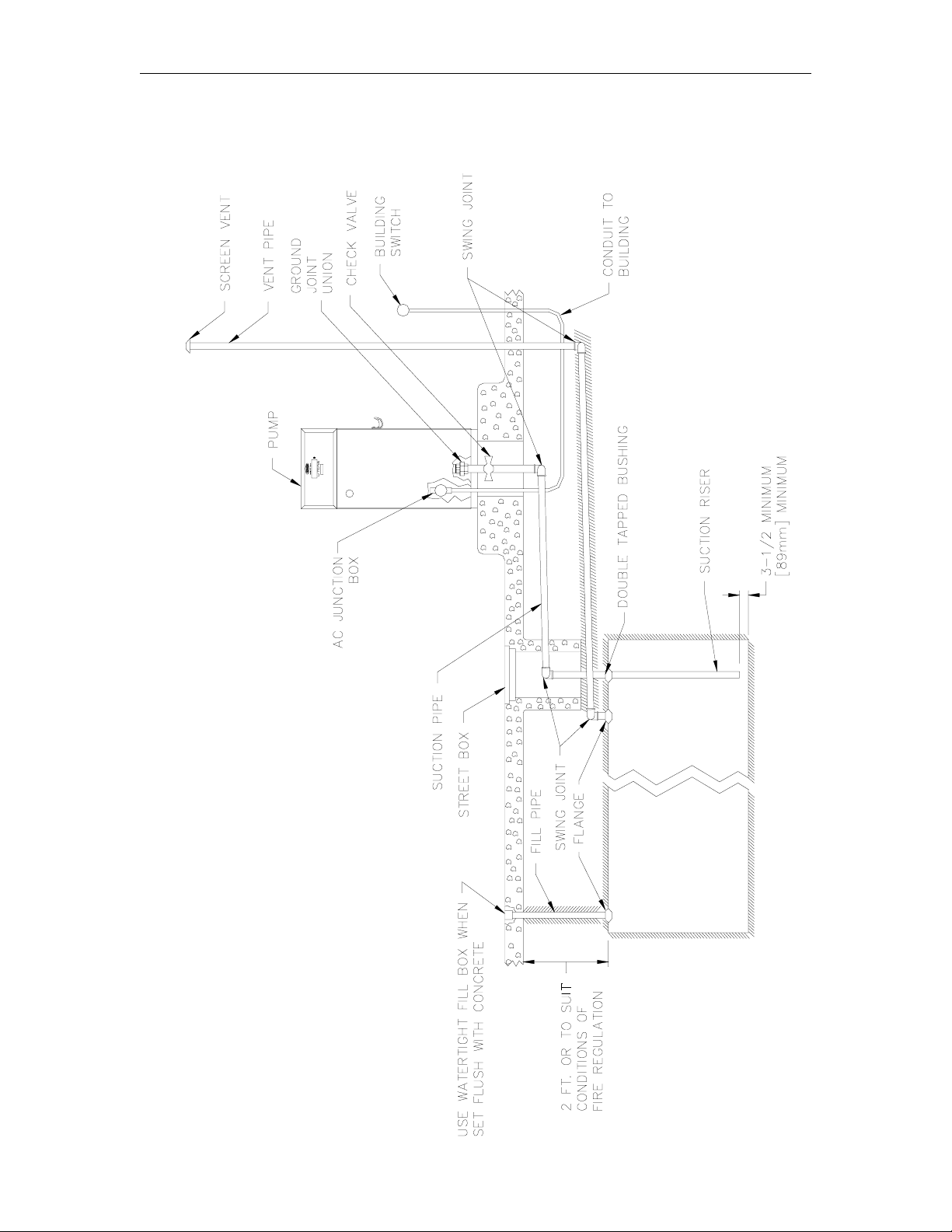
Installation
INSTALLATION LAYOUT
03/07/03 2-3
Page 10

GASBOY 552A/553A Commercial Pumps
SUPPLY LINE
Always start at the pump and work toward the tank. Use new galvanized or fiberglass (see note)
pipe, 1-1/2" minimum diameter. (NOTE: Fiberglass pipe is to be installed according to
manufacturer’s specifications and requirements.)
Be sure both the pipe and the tank are clean. Foreign matter entering the pump can cause
extensive damage. Obstructions in the supply line can create pump problems and reduced flow
rate.
Make sure all pipe threads ar e proper ly cut and the inside r eamed to remove bur r s. Use UL-listed
gasoline-resistant compound on all joints of gasoline handling piping. Sealing compound must
also be resistant to Gasohol (Ethanol and Methanol). Do not use Teflon Pipe Sealing Tape. Use
gasoline-resistant pipe compound on male threads only; pipe compound used on female threads
can be squeezed into the supply line where it can enter the product stream and become lodged in
the pump or meter. Install swing joints under the pump and at the tank to avoid breaks in the
supply line from settling or frost heave.
To avoid product delivery problems on suction pumps, be sure there are no traps in the supply
line. Supply lines, for both suction pumps and submersible pumps, should go straight down
beneath the pump to a point 18 inches (46cm) below the ground level and pitch at a rate of 1/8
inch per foot (1cm/m) from there down to the storage tank. The supply line should be as short and
direct as possible with swing joints (two 90
the horizontal run of pipe at 10-foot (305cm) intervals to maintain pitch and prevent traps. Do not
use wood as pipe supports.
New EPA regulations require that only one check valve be used per supply line and located
directly below, and as close as practical to the suction pump. Do not use spring-loaded or union
check valves since these will unnecessarily reduce the flow rate and contribute to the reduction of
atmospheric pressure necessary to keep gasoline in a liquid state.
Upon completion of installation, all liquid-carrying lines must be checked for leaks.
Connecting the Suction Pipe
To connect the suction pipe, remove the tin protector from the flange opening in storage tank.
Assemble suction pipe, double tapped bushing and foot valve with suction screen. Insert into
tank, and tighten in position. Starting at suction nipple at base of pump, take pipe measurements
to union elbow on suction pipe riser at top of tank. Cut pipe, assembly together loosely. If
measurements are correct, uncouple all pipe joints and coat them up with a good grade of
gasoline-resistant sealing compound. If pipe measurements are incorrect, a new pipe must be
cut.
NOTE: Underneath pump, a high grade valve with pressure relief must be used in suction
line.
o
elbows and one shoulder nipple) at all turns. Support
2-4 03/07/03
Page 11
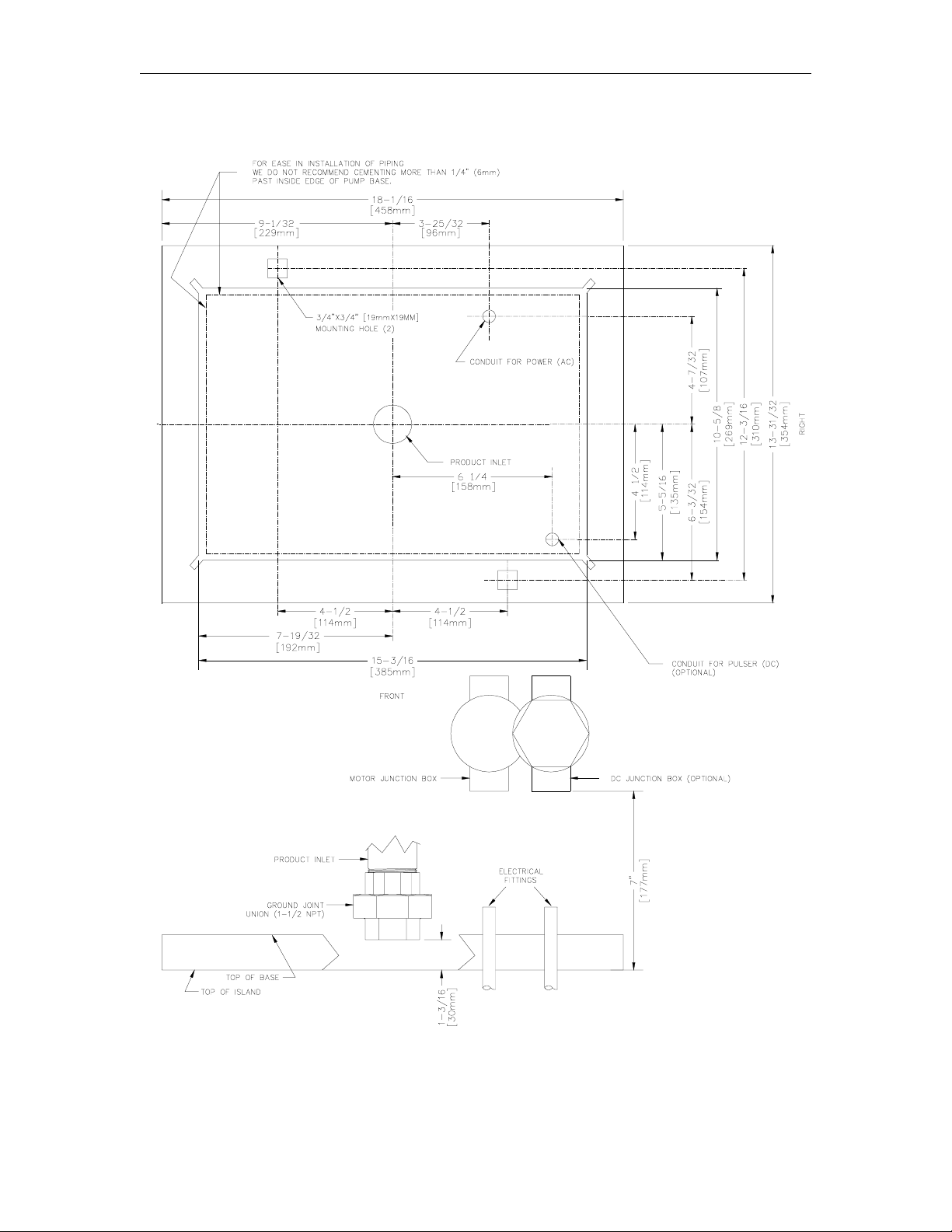
Installation
BASE LAYOUT - 011982
03/07/03 2-5
Page 12

Page 13

Section 3
WIRING
Customers & installers having any questions pertaining to the installation should contact
their GASBOY distributor.
WIRING PRECAUTIONS
The quality of the electrical installation is a major factor in maintaining proper safety levels and
providing trouble-free operation of your pump. To assure a quality installation, follow these rules:
1. All wiring must be installed to conform with all building/fire codes, all Federal, State, and
Local codes, National Electrical Code, (NFPA 70), NFPA 30, and Automotive and Marine
Service Station Code (NFPA 30A) codes and regulations. Canadian users must also comply
with the Canadian Electrical Code.
2. Use only threaded, rigid, metal conduit.
3. Use only UL-approved insulated gasoline- and oil-resistant stranded copper wiring of the
proper size.
4. Wire connections should be tightly spliced and secured with a wire nut; close off the open end
of the wire nut with electrical tape.
5. The line to the motor should be on a separate circuit and installed on a 20 to 30 AMP breaker
depending on the motor size and/or the voltage setting.
6. Install an emergency power cutoff. In addition to circuit breaker requirements of NFPA 70
and NFPA 30A, a single control which simultaneously removes AC power from all site
dispensing equipment is recommended. This control must be readily accessible, clearly
labeled, and in accordance with all local codes.
In order to provide the highest level of safety to you, your employees, and customers, we
recommend that all employees be trained as to the location and procedure for turning off
power to the entire system.
WARNING:
To reduce the risk of electrical shock when servicing, turn off and lock out
all power to the pump.
7. Have the pump installed by a competent installer/electrician.
GROUNDING
To ensure proper operation of the equipment and provide the necessary safety factors, this unit
must be grounded. A ground wire (preferably green) must be connected between the unit’s AC
junction box ground lug and the main electrical service panel. One (1) ear th ground connection is
required per unit. The ground rod is to be a solid, corrosion-resistant conductor and must be
installed at the main electrical panel in accordance with the National Electrical Code. It should be
properly tied into the ground bus strip of the panel. We recommend the neutral and ground bus
strips be bonded together (unless prohibited by local codes).
03/07/03 3-1
Page 14
GASBOY 552A/553A Commercial Pumps
CIRCUIT BREAKERS
Power to the unit must be supplied from a dedicated 20 to 30 amp breaker. No other equipment
should be powered from this breaker. A tag on the motor identifies the maximum curr ent draw of
the motor. If two units are supplied from one breaker, that breaker must be capable of handling
the load of both motors.
PUMP MOTOR
Pumps are shipped from the factory with motors wired according to the specifications given on the
order as to kind of current, frequency and voltage.
Very often on installation, it becomes necessary to change the original setting to suit the AC power
source. To do this, locate the motor change-over plate (typically located on the shaft end of the
motor) and remove the screw which secures it in place. Slide the plate so that the desired
voltage, as marked on the plate, lines up with the screw hole. Reinsert the screw and secur e the
plate in place. 380 VAC pumps are permanently set and cannot be changed.
Many motor failures result from improper setting of the motor change-over plate. If set for 120
VAC and a 240 VAC feed is used, the motor will burn out after running only a short time. If set for
240 VAC and a 120 VAC feed is used, the motor will run very slowly and the starting field will soon
burn out.
WIRING AND CONDUIT
Pump Wiring
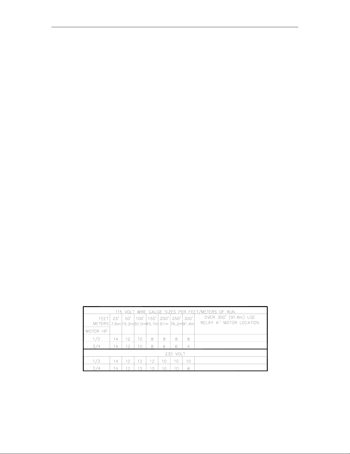
The table below shows the required AC wire size based on the HP rating of the pump motor and
the distance from the circuit breaker to the pump for both 115 and 230 volt units. Use this table as
a guide for selecting the proper size wire for your installation. Consult local wiring requirements
for wiring of 380 VAC motors.
If multiple units are powered from the same breaker through the same wires, you must increase
the gauge of the wires to handle the added load according to the distance from the breaker panel
and the HP rating (if applicable).
Wire Size
3-2 03/07/03
Page 15

Wiring
Pulser Wiring
Pulser wiring must be 18AWG. If it is run in the same conduit as the AC wiring, it must also
conform to the following wiring requirements:
• Wire must be 2-wire twisted-pair Belden 88760 (C08850) or 4-wire Belden 89418 or
equivalent (C08864).
Both types of cable provide superior noise immunity and are rated as follows:
Belden 88760
Gas and oil resistant insulation & jacket
18 AWG tinned, stranded, copper
One twisted pair (two conductors)
300 volt maximum operating voltage
Aluminum/Mylar shielded w/drain wire
NOTE: If using 88760 cable with a 3-wire pulser, you must run two lengths of cable to
attain two twisted pairs (four conductors). Cap off the unused wire.
Belden 89418:
Gas and oil resistant insulation & jacket
18 AWG tinned, stranded, copper
Stranded, four conductors
300 volt maximum operating voltage
Aluminum/Mylar shielded w/drain wire
• Cable connections to pulser must be made in DC junction box. Pulser cables will pass
through AC junction box.
• Cable drain wire must be connected to the grounding screw in the DC junction box in the
pump/dispenser. The drain wire is not connected at the fuel management system end.
• Rigid metal conduit must be used to connect the AC and DC junction boxes.
Conduit
All wiring to the Gasboy 550A Series dispensing unit must be installed in threaded, rigid, metal
conduit. PVC is not acceptable. It is recommended that DC pulser wiring be run in separate
conduit from any AC wiring; however, it is acceptable to run DC pulser wiring in the same conduit
as AC wiring as long as the requirements outlined in Pulser Wiring are met.
All wiring and conduit runs must also conform with the National Electrical Code (NFPA 70) and the
Automotive and Marine Service Station Code (NFPA 30A). All wiring and conduit runs must
conform to local codes. Canadian users must also comply with the Canadian Electrical Code.
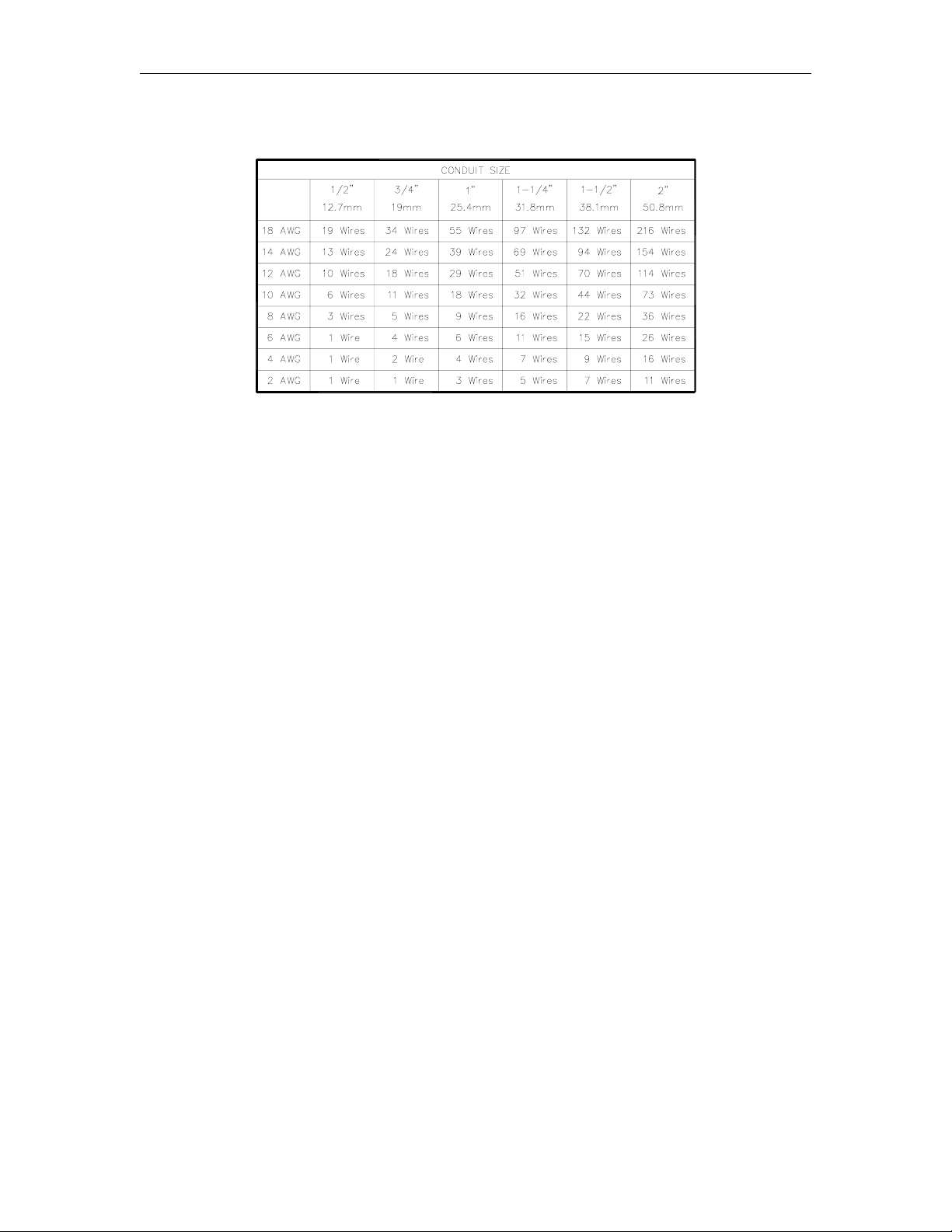
The table that follows shows conduit capacity for rigid, metal conduit with a 50% fill of gas- and
oil-resistant wire. Use this chart as a guideline to determine the proper conduit sizes for the
Gasboy 550A Series dispensing units. When planning the orientation of the wiring runs, follow the
applicable wiring diagram and consider the layout of the components at the site. Long runs or a
large number of bends may require you to increase conduit size over what is listed.
03/07/03 3-3
Page 16
GASBOY 552A/553A Commercial Pumps
Conduit Size
To connect the rigid conduit for the motor, start at the electrical connection box in pedestal of
pump, and take necessary measurements for pipe between motor and switchboard in building.
The conduit must be connected to make it water-and vapor-tight. Do not use flexible conduit.
When pulling wires through conduits, be careful not to damage insulation or break wires. To
connect wires, ends of wires must have insulation removed. Splice them tightly together, apply
solder, and follow with an application of electrical tape equal in thickness to insulation of wire
leads.
WIRING NOTES
1. All wiring and conduit runs must conform with all building/fire codes, all Federal, State, and
Local codes, National Electrical Code, (NFPA 70), NFPA 30, and Automotive and Marine
Service Station Code (NFPA 30A) codes and regulations.
2. The brown wire (Switch Detect) is shipped capped from the factory. When used, it connects
to a solenoid valve or fuel management system. Do not connect this wire without first
checking the ON voltage of this line to ascertain compatibility with the equipment being
connected.
3. All wiring must be installed according to the requirements outlined in this section.
3-4 03/07/03
Page 17
Wiring
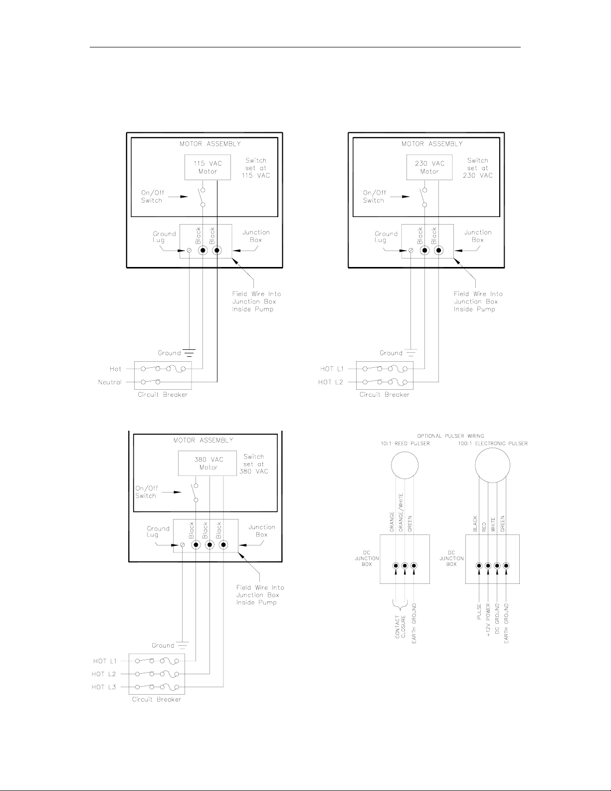
WIRING DIAGRAM - 024206
115 VAC Wiring 230 VAC Wiring
380 VAC Wiring Pulser Wiring
03/07/03 3-5
Page 18

Page 19

Section 4
TESTING AND OPERATION
TESTING THE INSTALLATION
Before placing the pump into full operation, you should first test the installation.
1. Place a small quantity of product in storage tank, but do not cover tank or pipe line
connections until pump is operated several times to make certain the system is fully primed
with product.
2. Operate pump several times, following instructions below, until gasoline is discharged from
hose nozzle. This will fill suction line and pump with gasoline.
3. Make a final inspection of all pipe lines to insure that connections are absolutely tight.
NOTE: If necessary for more than one pump to be connected to a single outlet from storage tank,
OPERATING INSTRUCTIONS
1. Reset register assembly to zero by turning instrument knob (located on left side panel) in a
CAUTION: On units equipped with a built-in interlock, failure to reset register before
2. Remove nozzle from nozzle hook.
3. Pull out switch rod and knob assembly (on right side panel). This will turn on motor and
4. Place nozzle into receiving vehicle and dispense desired quantity of product into vehicle.
5. Upon completion of delivery, push switch r od and knob assembly in. This will turn the motor
6. Replace nozzle on nozzle hook.
it is imperative that high grade check valves be used in each line to pumps, and must be
placed as close as possible to the connection into main supply line from tank. This is to
prevent a partial vacuum being created in suction lines, causing pumps to operate in a
pulsating manner.
counterclockwise direction.
attempting to turn dispenser on may result in damage to reset mechanism.
activate the pump.
NOTE: Nozzle must be manually held open at all times.
and pump off.
03/07/03 4-1
Page 20

Page 21

Section 5
MAINTENANCE AND TROUBLESHOOTING
GENERAL
GASBOY pumps are designed and constructed to give many years of uninterrupted service. In
fact, hundreds of operators report years of trouble-free operation with absolutely no service
expense. Yet, certain parts of a pump are bound to wear, and GASBOY therefore recommends a
periodic inspection, at least twice a year, for such things as fuel leaks, belt tension and condition,
lubrication and strainer cleanliness. If such a procedure is followed, any small adjustments that
are necessary can be made before expensive, annoying breakdowns occur. The result of this
sound approach is continuous, profitable service from all of your GASBOY equipment.
Procedures requiring disassembly of portions of the pump should be performed by
qualified service personnel.
WARNING:
To reduce the risk of electrical shock when servicing, turn off and lock out all
power to the pump. Always turn off and lock out all power to the pump at the
master panel before performing any maintenance or service, including the
changing of any fuel filters or strainers. Also block islands so no vehicles can pull
up to the pump while it is being worked on.
Where to Get Help: If your pump should stop or fail to operate properly, GASBOY has a
distributor network which services fuel dispensing and management systems in every section of
the country.
Use Authorized Parts: Parts needing replacement should be replaced only with GASBOY new
authorized service parts. This will ensur e the best results and the continuity of the Underwriters’
Label on your pump. Incorrect or substandard parts can result in unsatisfactory pump operation.
Always use new gaskets or seals when servicing or rebuilding GASBOY equipment; do not re-use
old ones.
EXTERIOR MAINTENANCE
The urethane finish on GASBOY pump housings is similar to that used on automobiles. Keep
your pump looking like new by thoroughly cleaning its exterior with a high grade automobile polish
and then protecting it with a coat of paste wax. Do not use abrasive cleaners or polish. Do not
use high pressure spraying equipment.
03/07/03 5-1
Page 22

GASBOY 552A/553A Commercial Pumps
LUBRICATING THE PUMP’S COMPONENTS
The following illustration shows the lubrication locations for your 550A Series pump.
Linkage Apply one drop of oil (SAE 10) at each pivot point of linkage every six months.
Register Every six months, or after each 100,000 gallons delivered, clean the register with
compressed air, and wipe all accessible parts (such as figure wheels) with a clean cloth. Use a
light, non-acid type oil (SAE 10), applying one drop between each figure wheel. Never use
solvents such as gasoline or kerosene, as they can become trapped in many of the inaccessible
bearings and dissolve the new lubricant when applied.
Motor Every three months, the oil the motor with 3 drops of high grade light oil (SAE 10) . Avoid
over-lubrication; more motors are damaged by too much, rather than too little, oil.
Rotary Pump & Air Separator Assembly O nce every six months, lubricate the felt with 1 oz. of
high grade light oil (SAE 10).
Meter Do not disassemble the meter for lubrication.
Gear Train Do not lubricate the gear train. It is permanently lubricated at the time of
manufacture.
5-2 03/07/03
Page 23

Maintenance and Troubleshooting
CLEANING THE STRAINER
Once every three months, remove strainer cap using the correct wrench and turning in
counterclockwise direction. Remove the strainer screen and clean it with compr essed air or by
rinsing in solvent.
NOTE: Always wear protective safety goggles or glasses when using compressed air.
Replace the gasket after cleaning the strainer screen and before reinstalling strainer cap. Be sure
strainer cap is drawn up tight after reinstalling, as a leak will prevent proper operation of pump.
CALIBRATING THE METER
All GASBOY pumps and dispensers are adjusted for accurate measure at the factor y. However,
since the conditions of the installation can affect pump accuracy, it is the responsibility of the
installer to check the pump for accuracy and make any needed adjustments. Where required, it is
the owner’s responsibility to report this device to the local Weights and Measures officials for their
inspection before the unit is put into service. Calibration methods are given in gallons. When
calibrating liter pumps, use the same procedure, but convert gallons to liters (1 gallon = 3.78
liters).
The adjustment of measurement is
accomplished by breaking the seal wire and
removing the Seal Pin. This will permit the
Index Disc, to be turned either
counterclockwise (-), decreasing the
measurement, or clockwise (+), increasing the
measurement. A variation of approximately
one cubic inch in measurement is obtained by
turning the Index Disc five holes. After
measurement has been properly adjusted, the
Seal Pin and seal wire should be replaced.
CORRECTING METER DRIVE SHAFT LEAK
If a leak develops around the meter drive shaft, it can be corrected as follows:
1. Remove screws and lockwashers securing gear train assembly and remove gear train
assembly.
2. Remove following items by lifting from meter cover packing cavity: upper bearing assembly,
washer, seal, o-ring, seal retaining ring, seal, o-ring, and seal retaining ring.
3. Reseal meter drive shaft by using the following new parts: seal, o-ring, seal retaining ring,
seal, o-ring, and seal retaining ring.
NOTE: Seals are to be formed to meter shaft size by rotating seals on a smooth 3/8" dia.
tapered punch or pencil. Be careful not to damage the seals in the forming
4. Reinstall parts in reverse order of disassembly.
Replacement of meter is recommended if the above procedures do not correct the
problem.
process or when inserting into packing cavity.
0124 5-3
Page 24

GASBOY 552A/553A Commercial Pumps
ADJUSTING THE BELTS
A loose belt reduces pump output due to slippage, and results in excessive wear. Once every six
months, check for proper V-belt tension. V- belt tension is proper when the back side of the belt
can be depressed approximately 3/8" (9.5mm). If adjustment is required, loosen cap screws and
pivot idler arm either upward or downward to obtain proper tension. Cap screws must be retightened before belt tension can be checked.
5-4 03/07/03
Page 25

Maintenance and Troubleshooting
TROUBLESHOOTING
Possible Cause Checks Corrective Action
Failure of bypass valve causes
pump to stall completely
Failure of regulating valve to
open prevents gasoline from
flowing to meter.
Failure of regulating valve to
close.
Failure of float needle valve to
open causes gasoline to be
discharged from air vent tube.
Presence of foreign material in
pump may cause bypass valve
to become stuck in its seat or
valve cylinder. Condition may
develop when a pump has
been idle for some time; when
water is present; or when ice
has formed.
Foreign matter may be lodged
in valve cylinder.
Insufficient pressure in supply
chamber due to break in
suction pipe, empty
underground storage tank,
clogged strainer screen, stuck
foot valve, needle valve,
extreme wear of parts or
excessive end play in rotary
pump head assembly, or ice
formation during cold weather,
if water is present in gasoline.
Valve may be held off its seat
by small particles of foreign
matter. Effect on normal pump
operation is not noticeable;
however, when the pump is
standing idle, even a slight
leak will permit gasoline to
drop down in the system.
May be caused by float being
clogged with gasoline, or by
corrosion of small pins (float
lever and valve pin) of needle
valve mechanism.
Float may be filled with product
caused by leak or puncture in
float.
Remove by-pass valve, clean
all parts, and reinstall the
valve.
Clean all parts and reinstall
valve.
Check list of possible causes
and perform appropriate
remedy.
Remove regulating valve and
clean dirt from poppet and
seat; reinstall.
If cork disc of regulating valve
is badly pitted or worn, replace
it with a new regulating valve.
Replace a damaged float with
a new one. Clean or replace
corroded parts.
Replace with new float
assembly.
0124 5-5
Page 26

GASBOY 552A/553A Commercial Pumps
PREPARING USED PUMPS FOR STORAGE
Special care should be taken when pumps are removed from service prior to storage. Gasoline,
moisture, and foreign material that is left in the pumps will do extensive damage to the internal
working parts. This damage can be prevented, if entire pump is drained of gasoline, moisture, and
foreign material before it is put into storage.
1. Remove drain plugs in r otary pump and separator body and in the top of meter cover. Then
lay pump on its side and elevate bottom of pump.
2. Apply compressed air (no gr eater that 50 pounds [3.5barr]) through suction inlet to force out
all gasoline, moisture, and foreign material that may be trapped in the inaccessible cavities.
Be sure to wear safety glasses when using compressed air.
3. Oil interior working parts by using a spray gun filled with light oil (free from gum content). The
oil may be blown in through the suction inlet.
4. Shellac drain plugs and reinstate them in their pr oper positions. Use a cloth bag or wooden
plug to cover the suction inlet and discharge outlet to prevent dirt from entering interior.
5-6 03/07/03
Page 27

Section 6
PARTS LIST
GENERAL
This section lists parts information for the 550A Series pumps. Using part numbers when order ing
will expedite your order and reduce the possibility of the wrong parts being shipped.
Procedures requiring disassembly of portions of the pump should be performed by competent
service personnel. Do not depend upon the repair service of a general mechanic unless he is
thoroughly familiar with the mechanism. GASBOY has a distributor network which services fuel
dispensing and management systems in every section of the country.
WARNING:
To reduce the risk of electrical shock when servicing, turn off and lock out all power to the pump.
Always turn off and lock out all power to the pumps at the master panel before performing
maintenance or service, including the changing of any fuel filters or strainers. Also block islands
so no vehicles can pull up to the pump while it is being worked on.
03/07/03 6-1
Page 28

GASBOY 552A/553A Series Commercial Pumps
PANELS AND TRIM DIAGRAM
6-2 03/07/03
Page 29

Parts List
PANELS AND TRIM PARTS
Item Part No. Description
1 Dial Enclosure Assembly (See Dial Enclosure breakdown)
2 035903 Dial Mask
3 024895 Elbow, 1” x 90°
4 017278 Bushing, reducer, ¾ x 1 (552A)
5 056913 Spacer
6 015104 Deflector
7 028960 Grommet, 1”
8 024544 Dome Assembly
9 038550 Nozzle Boot
10 035000 Right Side Panel
11 030847 Rear Panel
12 024518 Front Door Panel
024563 Front Door Panel for units with Hand Crank Option
13 015890 Hose Support Hook
14 017005 Nozzle Hook
15 033007 Switch Rod and Knob Assembly
16 045805 Latch Plate
17 058021 Grommet
18 045804 Plate
19 035002 Left Side Panel
20 032714 Reset Knob
21 057402 Spring Clip
22 027073 Gasket, 2”
23 027073 Cushion, 38-3/8
24 027072 Cushion, 30-1/2
NOTE: Specify standard color (black, white, red). If not a standard color, specify serial
number of pump/dispenser.
(See Note)
(See Note)
(See Note)
(See Note)
(See Note)
1212 6-3
Page 30

GASBOY 552A/553A Series Commercial Pumps
CHASSIS ASSEMBLY - FRONT AND REAR VIEW DIAGRAM
6-4 03/07/03
Page 31

Parts List
CHASSIS ASSEMBLY - FRONT AND REAR VIEW PARTS
Item Part No. Description
1 Register Assy. w/start-stop l inkage
Register Assy. w/Int erlock
(See breakdown for your model)
2 045774 Counter Support Plate
3 047511 Corner Post, Right Front
4 044016 Discharge Pipe
5 026071 Meter flange
6 027004 O-Ring
7 063969 Meter Support
8 Meter Assembly (See breakdown for your model)
11 012148 V-Belt 4L330
12 Motor Assembly (See breakdown for your model)
13 047510 Corner Post, Rear
14 Pump Assembly (See breakdown for your model)
16 011902 Base
17 Flange Assembly (See Meter Assembly breakdown)
18 047512 Corner Post, Left Front
19 Pulser Assembly (See Pulser Assembly breakdown)
20 Hand Crank Assembly (See Hand Crank breakdown)
03/07/03 6-5
5
Page 32
GASBOY 552A/553A Series Commercial Pumps
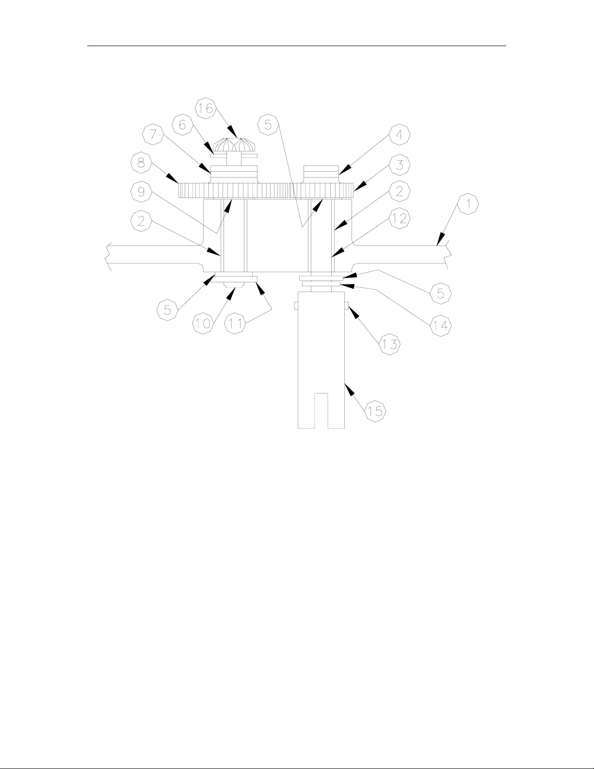
ADAPTER ASSEMBLY
Item Part No. Description
1 003612 Adapter
2 011065 Bearing Insert
3 027447 Drive Gear
4 043031 Roll Pin, 1/16 Dia x 3/8 Lg.
5 068041 Washer
6 043246 Spirol Pin, .039 x 1/2 Lg.
7 043032 Roll Pin, 1/16 Dia. X 1/2 Lg.
8 027446 Driven Gear
9 068016 Thrust Washer
10 054437 Shaft
11 048629 Truarc Retaining Ring
12 054444 Shaft
13 043227 Spirol Pin, 3/32 Dia. X 3/4 Lg.
14 049406 Retaining Ring
15 054829 Shaft, Drive
16 S00146 Bevel Drive Gear
6-6 03/07/03
Page 33

Parts List
DIAL ENCLOSURE ASSEMBLY
Item Part No. Description
1 026333 Dial Enclosure Assembly, Complete
This assembly includes all items listed below. When ordering a complete dial enclosure
assembly, you must also specify either 025689 (Gallons silkscreen) or 026161 (Litres
silkscreen). For other customized silkscreens, include the serial number of your dispenser
with your order. Standard silkscreens have a white background with black text.
2 025689 Dial Glass, Gallons
026161 Dial Glass, Litres
For all other applications, specify the serial number of the pump.
3 025935 Frame, Dial
4 023871 Dial Enclosure
5 057403 Spring Clip
6 020819 Clip Dial Glass Assembly
03/07/03 6-7
Page 34

GASBOY 552A/553A Series Commercial Pumps
METER ASSEMBLY DIAGRAM
6-8 03/07/03
Page 35

Parts List
METER ASSEMBLY PARTS
Item Part No. Description
1 035589 Meter Assembly, Gallons
035588 Meter Assembly, Imperial Gallons
035556 Meter Assembly, Liters
2 027038 Meter Transfer Body Gasket
3 035514 Meter Transfer Body
4 003613 Inlet Connection
5 S00162 Gasket
6 021950 Coupling
7 026079 Flange
8 051950 Screw, HHC, 5/16-18 x 1-3/4
9 068005 Washer, 1/4
10 068875 Lockwasher, 5/16
11 049014 O-Ring
M49014 O-Ring, Methanol
12 027797 Gasket
13 042130 Pin
03/07/03 6-7
Page 36

GASBOY 552A/553A Series Commercial Pumps
METER ASSEMBLY BREAKDOWN DIAGRAM
6-8 03/07/03
Page 37

Parts List
METER ASSEMBLY BREAKDOWN PARTS
035589 Meter Assy., Gallon
035588 Meter Assy., Imp. Gallon
035556 Meter Assy., Liter
Item Part No. Description
1 S00466 Packing Gland Plate
2 S00467 Seal Pin
3 S00469 Compensator Screw Spring
4 S00473 Drive Shaft
5 069080 Seal & Seal Wire
6 S00475 Special Screw
7 S00476 Drive Shaft Pin
8 S00477 1/2" Ball
9 S00480 Plunger Cup Support
10 S00481 Plunger Disc
11 S00482 Washer
12 S00483 Washer
13 S00484 Upper Bearing Assembly
14 S00485 Bearing Assembly
15 S00487 Compensator Index Disc
16 S00488 Seal Half
17 S00489 Seal Wedge
18 S00490 Washer
19 S00492 Packing Spring
20 S00493 Seal
23 S00494 Bearing Retainer
24 S00495 Seal (black)
25 S00491 Seal Retaining Ring
26 S00478 Compensator Pinion
27 S00512 Screw
28 S00498 Main Pivot Bracket Assembly
w/ Pins
29 S00032 Plunger Cup Kit (Set of 3
Cups)
30 S00501 Valve
31 S00502 Wobble Plate w/ Slack Roller
Post
32 S00503 Connector
33 S00504 Bearing Seat
35 S00505 Slack Roller Assembly
36 S00506 Slack Spring Assembly
37 S00496 Drive Shaft Gear - Gal
S00115 Drive Shaft Gear - Ltr
Item Part No. Description
38 S00499 Counter Drive Gear Complete -
Gal
S00114 Counter Drive Gear Complete -
Ltr
39 S00497 Compensator Shaft
40 S00500 Bracket & Pin Assembly
41 S00468 Index Plate
42 S00479 Pivot & Ball Assembly
43 S00470 Meter Body Gasket
44 S00471 O-Ring (.362 Dia.)
45 S00472 O-Ring (.487 Dia)
46 S00486 Meter Cover w/ Center Gear
Post, Index Plate, Pipe Plug &
Retaining Ring
47 S00509 Mach. Screw, 10-32 x 3/8 Lg.
Rd. Hd.
48 S00507 Mach. Screw, #12-24 x 1/2 Lg.
Rd. Hd.
49 S00508 Mach. Screw, 1/4-20 x 3/4 Lg.
Rd. Hd.
50 S00511 Hex Nut, 1/4-20
51 S00510 Hex Nut, 5/16-18
52 S00520 Lockwasher, 1/4
53 S00513 Lockwasher, #1212
54 S00514 Lockwasher, #1114
55 S00515 Pipe Plug, 1/8 Sq. Hd.
56 S00516 Sems Fastener, #10-32 x 3/8
Lg. Rd. Hd.
57 S00517 Cotter Pin, 1/16 x 1/4 Lg.
58 S00518 Truarc Retaining Ring
59 S00519 Truarc "E" Retaining Ring
60 S00521 Plunger Assy. w/ Bearing
Retainer, Bearing Seat & Sems
Fastener
61 S00522 Body & Seat Assembly w/Pins
62 S00523 Meter Drive Shaft Kit
63 S00130 Shaft-Seal Kit
03/07/03 6-11
Page 38

GASBOY 552A/553A Series Commercial Pumps
MOTOR ASSEMBLY DIAGRAM
6-12 03/07/03
Page 39

Parts List
MOTOR ASSEMBLY PARTS
Item Part No. Description
1 F37630 Motor, ½ HP, 552A, 115V/230V, 50Hz./60Hz.
F37609 Motor, ¾ HP, 553AMC, 115V/230V, 50Hz./60Hz.
F37320 Motor, ¾ HP, 553AMC, 380V/50Hz., 3 Ph
F37323 Motor, ¾ HP, 553AMC, 115V/230V, 50Hz./60Hz. For tropical environments.
2 031315 Key
3 047005 Pulley, 5/8 Bore 2.4, 552A
047023 Pulley, 5/8 Bore, 3-1/4, 553AMC
4 038050 Pipe TBE, 1/2 x 1-1/8
5 014165 J-Box, 550
6 014164 Conn. Box Cover
7 063967 Bracket, Motor Right
8 051925 Screw, 5/16-18 x 1-1/4 HHC Pl
9 068080 Washer, 5/16 Pltd.
10 067735 Washer, Cup
11 037884 Mount, Rubber
12 068620 Washer, 5/16 x 1 x 3/64
13 037885 Mount, Rubber
14 038920 Nut, Lock, 5/16-18 Hex
15 021030 Conduit Conn.
03/07/03 6-13
Page 40

GASBOY 552A/553A Series Commercial Pumps
PUMPING UNIT ASSEMBLY DIAGRAM
6-14 03/07/03
Page 41

Parts List
PUMPING UNIT ASSEMBLY PARTS
Item Part No. Description
1 021935 Coupling, Nipple
2 047009 Pulley, Idler
3 026038 Fitting, Ell, ¼ x 3/8
4 056605 Sleeve, Compression
5 038555 Nut, Compression
6 063633 Tube, Vent
7 047029 Idler Arm
8 048424 Pumping Unit, 553AMC
048227 Pumping Unit, 552A
9 031315 Key
10 047598 Pulley, 3/4 bore, 4, 553AMC, 60Hz.
047597 Pulley, 3/4 bore, 3-1/2, 553AMC, 50 Hz.
047015 Pulley, 3/4 bore, 5-1/4, 552A, 50 Hz./60Hz.
11 063968 Bracket, Pump Left
12 066385 Union, 1-1/2 #150 Stockham
13 044907 Pipe TBE, 1-1/2 x 2-1/4
14 063966 Bracket, Motor Left
15 067735 Washer, Cup
16 037884 Mount, Rubber
17 037885 Mount, Rubber
18 068875 Washer, Std. Spring Lock, 5/16
19 051925 Screw, 5/16-18 x 1-1/4 HHC
20 063965 Pump Support, Right
03/07/03 6-15
Page 42

GASBOY 552A/553A Series Commercial Pumps
PUMPING UNIT ASSEMBLY BREAKDOWN DIAGRAM
6-16 03/07/03
Page 43

Parts List
PUMPING UNIT ASSEMBLY BREAKDOWN PARTS
048227 Pumping Unit Assy., 552A
048424 Pumping Unit Assy., 553AMC
Item Part No. Description
1 S00117 Gasket
2 S00456 Float Lever Pin
3 S00066 Valve Pin
4 S00067 Guide Plate
5 S00068 Spring Plate
6 S00069 Plunger Head
7 S00072 Plunger Plate
8 S00073 Plunger Follower
9 S00074 Valve Cylinder
10 S00075 Cylinder Head
11 S00076 Clamp Plate
12 S00077 Float Valve Body
13 S00078 By-Pass Valve Spring (#34 to
35-1/2# spring)
S00079 By-Pass Valve Spring (44-1/2#
Spring)
14 S00080 Vent Screw
15 S00062 Valve Cylinder Gasket
16 S00081 Vent Screw Guard
17 S00082 Float Valve Needle
18 S00083 Float Valve Gasket
19 S00128 Pump Rotor Shaft Assembly
20 S00119 Bottom Head Gasket
21 S00084 Separator Cover
22 S00120 Cover Gasket
23 S00085 Retainer
24 S00121 Bearing
25 S00086 Regulating Poppet Assy
26 S00124 Oil Well Felt
27 S00061 Float Assembly
29 S00087 Gasket
30 063312 Suction Screen (Gasoline)
063313 Suction Screen (Diesel)
31 S00088 Regulating Valve Spring
32 S00089 By-pass Valve Poppet
33 S00056 Packing Gland
34 S00090 Packing Spring
35 S00091 Rotary Pump & Separator
Body w/Gasket, Bearing,
Screws & Spring
36 S00092 Regulating Valve Seat
37 S00093 Valve Seat Guide
38 S00094 By-pass Valve Seat
39 S00448 Check Valve Cap
41 S00447 Poppet Spring
43 S00116 "V" Packing
44 S00095 Plunger Guide
Item Part No. Description
45 S00096 Plunger Disc
46 S00097 Plunger Spacer
47 S00122 Drive Shaft Bearing
48 S00129 Rotary Pump Idler
50 S00098 Poppet Disc. & Relief Valve
Assy
52 S00427 Suction Strainer Cap
53 S00125 By-pass Valve Assembly (34#
to 35-1/2# spring), 552A
S00126 By-pass Valve Assembly (44-
1/2# spring), 553AMC
54 S00127 Regulating Valve Assembly
55 S00123 Gasket
56 S00451 1/4-20 x 7/8 Lg. Rd. Hd. Mach
Screw
57 S00452 1/4-20 x 1/2 Lg. Hex Hd. Cap
Screw
58 S00453 5/16-18 x 7/8 Lg. Hex. Hd. Cap
Screw
59 S00454 3/8-16 x 2-3/4 Lg. Hex. Hd.
Cap Screw
60 S00455 3/8-16 x 1-1/8 Lg. Hex. Hd.
Cap Screw.
61 S00458 3/8 Lockwasher
62 S00457 1/16 x 1/2 Lg. Cotter Pin
63 S00459 1/4 Sq. Hd. Pipe Plug
64 S00460 1/4 Countersunk Pipe Plug
65 S00461 1/4 - 28 Hex. Nut
67 S00462 Lower Pump Head w/Valve
Seat Guides, Regulating Valve
Seat & By-pass Valve Seat
68 S00057 Rotary Pump Head Assembly
03/07/03 6-17
Page 44

GASBOY 552A/553A Series Commercial Pumps
REGISTER ASSEMBLY WITH START-STOP LINKAGE DIAGRAM
6-18 03/07/03
Page 45

Parts List
REGISTER ASSEMBLY WITH START-STOP LINKAGE PARTS
Item Part No. Description
1 051211 Reset Rod
2 063964 Support Rod
3 049425 E-Ring
4 068042 Thrust Washer, 9/16OD x .382ID
5 022011 Coupling, Reset
6 022997 Coupling Kit
7 056917 Spacer, 7/32ID x 1/2OD x 13/32
8 050250 Rod End
10 017002 Switch, Arm
11 017001 Bracket, Support
12 051215 Rod, Switch
13 042430 Pin, Cotter, 1/16 x 1/2
14 056915 Spacer, .314ID x .434 OD x .145
15 S00173 Totalizer Assembly
16 056916 Spacer, 7/32ID x 1/2OD x 3/16
17 010070 Adapter Assembly (See breakdown)
18 048456 Register and adapter assembly (includes item 15, totalizer assembly)
*048456 Register (subcomponent of 048456)
03/07/03 6-19
Page 46
GASBOY 552A/553A Series Commercial Pumps
REGISTER ASSEMBLY WITH INTERLOCK DIAGRAM
6-20 03/07/03
Page 47

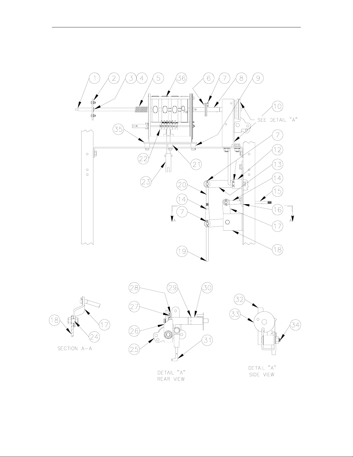
Parts List
REGISTER ASSEMBLY WITH INTERLOCK PARTS
Item Part No. Description
1 051213 Rod, Reset
2 063964 Rod, Support
3 049425 E-Ring
4 068042 Washer, Thrust, 9/16OD x .382ID
5 022011 Coupling, Reset, 550
6 043016 Pin, Seal, Special
7 042430 Pin, Cotter
8 021918 Coupling and Disc Assembly
9 056917 Spacer, 7/32ID x 1/2OD x 13/32
10 017003 Bracket, Interlock Support
12 056912 Spacer, Interlock
13 017008 Arm, 550
14 050250 Rod, End
15 051209 Rod, Switch Handle
16 015748 Support Bracket
17 017002 Switch Arm
18 017001 Support Bracket
19 051215 Rod, Switch
20 050022 Rod, Interlock
21 056916 Spacer, 7/32ID x 1/2OD x 3/16
22 S00173 Totalizer Assembly
23 022997 Coupling Kit
24 056915 Spacer, .314ID x .434OD x .145
25 017519 Cam, Reset Locking
26 057132 Spring, Interlock Cam
27 057131 Spring, Blocking Cam
28 012525 Block, Switch lever
29 043035 Pin, Roll 1/8 x ¾
30 021880 Coupling and Pin Assembly
31 050021 Rod, Interlock
32 017006 Support Interlock
33 048504 Reset and Shaft Assembly
34 054441 Shaft, Interlock
35 010070 Adapter Assembly (See breakdown)
36 048454 Register and Adapter assembly (includes item 22, totalizer assembly)
*048562 Register (subcomponent of 048454)
03/07/03 6-21
Page 48
GASBOY 552A/553A Series Commercial Pumps
HAND CRANK ASSEMBLY DIAGRAM
6-22 03/07/03
Page 49

Parts List
HAND CRANK ASSEMBLY PARTS
Item Part No. Description
1 038605 Nut, 5/16-18 Hex Keps
2 030803 Bearing-Pltd Assy.
3 030024 Housing/Bearing Assy.
4 055004 Shaft, Drive
5 048710 Pulley, 5-1/2 x .5 bore
6 053731 Screw, 1/4-20 x 5/8 Sq. Hd Set Cad Case Hardened
7 017130 Bushing, Hand Crank
8 014835 Bracket, Pulley
9 012166 Belt, 4L230, A21
10 051895 Screw, 5/16-18-3/4 HHC Pl
11 068875 Washer, Std. Spring Lock, 5/16
12 068080 Washer, 5/16-18 x 1/2
13 012168 Belt, 4L520-A50
14 048709 Pulley, 2" x 5" Bore
15 052010 Screw, Set 5/16-18 x 1/2
16 055005 Shaft, Drive
17 023139 Handcrank Assy.
18 068040 Washer, .505ID x .880OD, .058T
19 030025 Housing/Bearing Assy. (dbl)
20 049403 Retaining Ring, .396 Dia. (units built after 3/99)
048612 Retaining Ring, Truarc, .468 Dia.
21 043030 Pin, Roll, 3/16 x 1
03/07/03 6-23
Page 50

GASBOY 552A/553A Series Commercial Pumps
PULSER ASSEMBLY DIAGRAM
6-24 03/07/03
Page 51

Parts List
PULSER ASSEMBLY PARTS
Item Part No. Description
1 021788 Pulser, 10:1
047648 Pulser, 100:1
2 011954 Bearing, Nyliner
3 042100 Pin, Driv-Lok, 3/32 x 5/8 Type E
4 042280 Pin, Driv-Lok, 3/32 x 5/8 Type A
5 053471 Screw, Set, Soc. Hd, 6-32 x 3/16
6 043221 Pin-Spirol, 1/16 x 3/4 CRS
7 068037 Washer, SS, .260 x .500 x .010
8 051790 Screw, 1/4-20 x 1/2 HHC
9 068155 Washer, 1/4’ Int. Tooth
10 054551 Shaft, Pulser
11 028415 Gear, Miter Pulser
12 015917 Bracket, Pulser
13 023006 Coupling, Pulser
14 021058 Cond. Fitting, 90
15 003345 Junction Box, Mchng
16 003515 Junction Box Cover, Mchng
17 028422 Gear, Miter 24T
18 052285 Screw, 5/16-18 x 5/8 HHC
19 038605 Nut, 5/16-18 Hex Keps
20 023069 Conduit, Pulser
21 C08125 Conduit Fit, 1/2’ Union FF
22 023007 Conduit, Pulser, Lower
23 020745 Clamp, Junction Box
24 051805 Screw, 1/4-20 x 5/8 HHC
25 038740 Nut, 1/4-20 Hex Hd. Jam
26 068005 Washer, 1/4 Pltd
27 068860 Washer, Std. Spring-Lock
28 014641 Bracket
o
MF
0220 6-25
Page 52

GASBOY 552A/553A Series Commercial Pumps
ACCESSORIES AND FIELD KITS
Drip Tray
011982 Directs fuel from an internal leak to the outside of the cabinet to minimize ground
contamination. Installed between island and dispenser.
Filter Kits and Elements
External standard speed filter kits, designed for flow up to 15 GPM. Typically used on Model 552A.
Methanol fuels require special methanol element listed below.
032115 External Standard Speed Filter Kit (includes adapter, standard speed particulate filter
element and pipe fittings)
032116 External Standard Speed Hydrosorb Filter Kit (includes adapter, standard speed
Hydrosorb filter element and pipe fittings)
Replacement Elements
026005 Standard (removes particulates only)
026042 Hydrosorb (removes water and particulates)
025909 Methanol (particulate removal in methanol and methanol blends where content exceeds
15%)
External High Flow Filter Kits
Typically used on Model 553AMC. Components in high flow kits are not designed for use with Methanol or
Methanol blends.
032754 External Single Element High Flow Kit (includes adapter, one high flow particulate filter
element and pipe fittings)
032755 External Single Element High Flow Hydrosorb Kit (includes adapter, one high flow
Hydrosorb filter element and pipe fittings)
Replacement Elements
025900 Standard (removes particulates only)
025901 Hydrosorb (removes water and particulates)
Pulser Kits
050003 1:1 Pulser (one pulse per unit of measure)
050002 10:1 Pulser (10 pulses per unit of measure)
050004 100:1 Pulser (100 pulses per unit of measure). Recommended for most applications.
6-26 03/07/03
Page 53

GW01 - 6/04/02 Rev. 1
WARRANTY
General Statements:
Gasboy International LLC. warrants all new equipment manufactured by Gasboy against defective m aterial and/or workmanship, f or the warranty
period specified below, when the equipment i s installed in accordanc e with specifications prepared by Gasboy.
This warranty does not cover damage caused by acci dent, abuse, Acts of God, lack of surveillance of automatic recording system s, negligence,
mis-application, faulty installation, i mproper or unauthorized maintenance, i nstallation or use in violat i on of product manuals, i nstructions, or warnings.
Under no circumstanc e shall Gasboy be liable for any indirect, special, or cons equent i al damages, losses , or expenses to include, but not limited
to, loss of product, los s of profits, litigation fees , or the use, or inability to use, our product f or any f or any purpos e whatsoever.
Parts Only - During the warranty period, Gasboy will, at its option, repair or replace defective parts returned transportat i on prepaid to its factory.
On-Site Labor Included - Gasboy will also provide, within the Continental United States and during the warranty period, the services of an
Authorized Service Representati ve (A S R) for on-site repair or replacement of defective parts.
Replacement Parts - A ny system com ponents that are not part of the origi nal system order, incl udi ng Island Card Readers, Pump Cont rol Uni ts, etc.,
are considered replacement part s.
Equipment Term Coverage
Commercial Pumps and Dispensers
Full-Cabinet Consumer Pum ps
Small Transfer Pumps, Meters,
Pressure Regulators
Keytrol One year from date of instal l ation or 18 mos. from date of
Fuel Management Systems :
- CFN/ Profit Point
- Series 1000/Fleetkey
- TopKAT
- Fuel Point Readers
(sold with new systems)
Additional Fuel Point Items:
- Fuel Point Readers sold for
retrofitting existing systems.
- Fuel Point vehicle and dispenser
components.
Encoders, Embos sers, Modems,
CRTs, and Logger Printers
Air Diaphragm Pumps Three years from date of purchas e (for full warranty
Items not m anufactured by Gasboy
(ex. automatic nozzles, hoses, swivels,
etc.)
Replacement Parts One year from date of Gasboy International's invoice to the
To the extent permitted by law, this warranty is made in lieu of all other warranties , expressed or implied, incl udi ng warranties of freedom from pat ent
infringement, or merchant abilit y, or fitness for a particular purpos e, or arising from a course of dealing or usage of t rade. No one is authorized to
vary the terms of the warranty nor may anyone make any warranty of representation, or assume any liability other than that herein stated, in
connection with the sale desc ri bed herei n. The acceptance of any order by Gasboy I nt ernational is expressly made subj ect to the purchaser's
agreement to these condit i ons.
One year from date of install ation or 18 mos. from date of
Gasboy International’s invoi ce to the purchaser, whichever
comes first.
One year from date of install ation or 18 mos. from date of
Gasboy International’s invoi ce to the purchaser, whichever
comes first.- Excepting the Model 2020 Hand Pump, which
has a 90-day warranty from date of GASBOY International’s
invoice.
Gasboy International’s invoi ce to the purchaser, whichever
comes first.
One year from date of start-up or 15 mos. from date of
Gasboy International’s invoi ce to the purchaser, whichever
comes first .- The basic warranty only applies to systems
which have been started up by a Gasboy Authorized Service
Representative (ASR).
One year from date of start-up or 15 mos. from date of
Gasboy International’s invoi ce to the purchaser,
whichever comes first.
Purchased with Fuel Management Syst em (Encoders,
Embossers only):
90 days from the date of s t art-up by a Gasboy ASR, or 180
days from date of Gasboy I nternational's invoice, whichever
occurs first.
Purchased with Fuel Management System
(Modems, CRTs, and Logger Printers only):
Matches system warranty.
Purchased Separately:
90 days from date of Gasboy International's
invoice to the purchaser.
description, see Price List).
Not warranted by Gasboy International (consul t original
manufacturer’s warranty).
purchaser.
GASBOY INTERNATIONAL LLC
P.O. Box 309, Lansdale, PA 19446 ● (800) 444-5579 ● FAX: (800) 444-5569 ● www.gasboy.com
Parts and Labor.
Parts Only.
Parts and Labor.
Parts and Labor.
Parts Only.
Purchased with System
(Encoders, Embos sers only):
Parts only.
Purchased with System (Modems,
CRTs, Logger Printers only):
Matches system warranty.
Purchased Separately:
Parts Only.
Parts Only.
Not Applicable.
Parts Only.
 Loading...