

Page 1

SERIES 4860
METER-REGISTER
INSTALLATION/OPERATION/PARTS
MANUAL
035352
Rev. 03/07/03
INSTALLERS - IMPORTANT
In addition to installation information, this manual contains warnings, safeguards
and procedures on the use and care of the Series 4860 Meter-Register. Please
leave this manual with the meter owner after the installation is complete.
Copyright 2003 by Gasboy International LLC All rights reserved.
The information in this document is confidential and proprietary. No further disclosure shall be made without
permission from Gasboy International LLC Gasboy International LLC believes that the information in this document
is accurate and reliable. However, we assume no responsibility for its use, nor for any infringements of patents or
other rights of third parties resulting from its use. We reserve the right to make changes at any time without notice.
GASBOY INTERNATIONAL LLC LANSDALE, PA
Page 2

IMPORTANT WARNINGS AND SAFEGUARDS
Gasoline and petroleum products are flammable. To avoid injury or death to persons or damage to equipment or
property, follow these listed warnings and other warnings and precautions outlined in this manual when installing, using,
or working around this equipment. Check with GASBOY Technical Services for compatibility of liquids with pump
materials.
TURN OFF AND LOCK OUT ALL POWER TO PUMP BEFORE PERFORMING SERVICE, MAINTENANCE OR IN THE EVENT
OF A FUEL SPILL.
All products must be installed by a
qualified installer and used in
conformance with all building, fire, and
environmental codes and other safety
requirements applicable to its
installation and use, including, but not
limited to, NFPA 30, NFPA 30A, NFPA
395 & NFPA 70. A qualified installer is
familiar with fuel systems installations
under the above stated building, fire,
and environmental codes and other
safety requirements for the particular
type of installation.
This product is only part of a fuel
dispensing system and additional
equipment and accessories, such as,
but not limited to, breakaway
connectors, shear valves, pressure
regulators, flow limiters, and other
safety devices may be necessary to
meet the applicable codes.
For maximum safety, we recommend
that all employees be trained as to the
location and procedure for turning off
power to th e en tir e syste m. Instr ucti ons
regarding proper operation of the
equipment along with the appropriate
safety warnings should be posted in
plain view at the fuel island.
Before performing service or
maintenance (including changing of fuel
filters or strainers) or in the event of a
fuel spill, turn off and lock out all power
to the system. In battery-powered
pumps, disconnect power source. In
submersible pump applications, turn off
and lock out power at the master panel
and close any impact valves to the
submersible pump and any other
dispensers which use that submersible
pump. AC power can feed back into a
shut-off dispenser when dispensers
share a common submersible pump or
starter relay. Also block islands so no
vehicles can pull up to the dispenser
when the dispenser is being worked on.
DO NOT use Teflon tape for any pipe
threads in the product.
DO NOT use consumer pumps for
pumping fuel or additives into aircraft.
DO NOT use commercial pumps for
direct fueling of aircraft without filters
and separators necessary to ensure
product purity.
DO NOT use where sanitary design is
required (for food products for human
consumption) or with water-based
liquids.
DO NOT smoke near the pump or when
using the pump.
DO NOT use near open flame or
electrical equipment which may ignite
fumes.
DO NOT permit the dispensing of
gasoline or other petroleum products
into a vehicle with its motor running.
DO NOT permit the dispensing of
gasoline or other petroleum products
into unapproved containers or into
approved containers in or on vehicles
including tru cks. All co ntai ners must be
filled on the ground to prevent static
discharge. Always use Approved and
Listed hoses and nozzles with electric
pumps and dispensers.
DO NOT block open the nozzle in any
manner. Nozzles shall conform to UL
and NFPA code requirements for
attended or unattended service.
DO ensure that the pump is equipped
with proper filters based on the product
being dispensed and its intended use.
DO wear safety goggles and protective
clothes when dispensing any liquid
which may be potentially harmful or
hazardous.
DO keep all parts of body and loose
clothing clear of belts, pulleys, and
other exposed moving parts at all times.
DO require washing and changing of
clothes if fuel is spilled on a person or
his/her clothing. Keep away from open
flames, sparks, or people smoking.
DO provide a receptacle for catching
product from pump/meter when
servicing.
DO clean up product spills on the
driveway. Turn off and lock out all
power prior to cleanup.
DO insure pump is properly grounded.
DO insure hose is compatible with fluid
being dispensed.
DO inspect hose, nozzle, and pump on
a regular basis for wear, damage, or
other conditions which may create a
safety or environmental hazard.
DO make sure all pipe threads are
properly cut and the inside reamed to
remove burrs. Use UL classified
gasoline-resisting compound on all
joints of gasoline handling piping.
Sealing compound must also be
resistant to Gasohol (Ethanol and
Methanol). Use gasoline-resistant pipe
compound on male threads only; pipe
compound used on female threads can
be squeezed into the supply line where
it can enter the product stream and
become lodged in the pump or meter.
DO ensure that junction box covers are
in place and properly tightened. Mating
surfaces between the box and cover
must be free of dirt, nicks, and
scratches. All unused entries into the
junction box must be properly plugged.
035282 Rev. 1267
GASBOY INTERNATIONAL LLC
707 North Valley Forge Rd. Lansdale, PA, 19446 ● (215) 855-4631 ● FAX: (215) 855-0341
Page 3

INSTALLATION/OPERATION/PARTS
INSTALLATION
The 4860 meter can be installed either vertically or horizontally in a piping system. The inlet and
outlet are 90
strainer in the meter inlet to prevent jamming from foreign material. A 40 mesh or finer basket is
required.
o
apart and can be rotated in relation to the register by 90o increments. Install a
OPERATING CHARACTERISTICS
The 4860 meter uses a nutating disc type measuring chamber and can be calibrated using an
adjusting screw. The pushbutton register records in gallons or liters up to 999 9/10. The totalizer
is a 7-wheel counter which records up to 999,999.9 gallons or liters. Pushing in the reset button
resets the four-wheel register to zero. Change gears permit the meter to be US gallons or liter
measure. The 4860 meter will accurately measure liquids with viscosities of less than 120 SSU
o
(60
F) (16oC) at flow rates fr om 4 to 15 G PM or 15 to 57 LPM. Although designed specifically for
petroleum products, the 4860 meter can be used in applications where the materials are
compatible with recommendations of the manufacturer of the chemical or substance under
consideration.
CALIBRATION
NOTES: This meter was redesigned causing the calibration procedure to be different depending
on the age of your meter. Meters made after May 10,1995 are referred to as new style
meters; meters made before that date are referred to as old style.
This meter is for consumer use only and not for re-sale. It is not sealable by Weights
and Measures.
All GASBOY meters are adjusted for accurate measure for diesel within +
factory. However, since the conditions of the installation can affect pump accuracy, it is the
responsibility of the installer to check the pump for accuracy and make any needed adjustments.
Choose the flow rate at which the meter will be used most often for the zero calibration point. For
example, if the pump is being used with an automatic nozzle, calibrate with the nozzle set on the
middle or top notch position, whichever is used most frequently.
Use a certified five-gallon measure with a sight glass and scale showing cubic inches over or
under an exact five gallons. Fill and drain the test measure to completely wet the interior surfaces.
Reset the register to zer o and deliver an exact measured five gallons into the test measur e at the
selected flow. Read the level of the liquid in the sight glass on the scale in +
03/07/03 1
.05 gallons at the
cubic inches.
Page 4
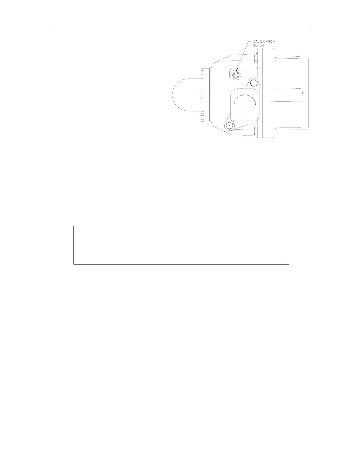
GASBOY Model 4860 Meter
For old style meters only, remove cap
screw, exposing the slotted head
calibration screw. Use a narrow blade
screw driver to turn the calibration screw
clockwise to correct for plus cubic inches
or counterclockwise for minus cubic inches
in the test measure.
Count the number of full turns and
fractional turns each time for reference in
judging the number and direction of any
additional turns required to calibrate the
meter to exact zero.
For new style meters, start with the screw turned all the way in clockwise. For gasoline
calibration, turn the screw approximately two full turns counter-clockwise. For diesel, turn the
screw approximately two additional full turns counter-clockwise.
Replace the cap screw (old style only) . Deliver about 1/2 gallon thr ough the meter before r esetting
to zero and retesting. Allow a ten second drain period each time the test measure is emptied to
assure accurate measure. Adjust and retest until register is zeroed at desired flow.
SERVICE
WARNING:
To reduce the risk of electrical shock when servicing, turn off and lock out all
power to the meter/pump.
NOTE: Numbers in parentheses correspond to the numbers shown on the parts illustration and
To service the pushbutton register, remove two (one on each side) screws (2) from bezel (1).
Remove bezel (1), gasket (3), and dial mask (4). Reset button (5) and spring (6) are released
when dial mask is removed. Remove screws (7), reset bearing (8 ) and screws (11) and lift out
register assembly. Drive shaft assembly (12) may be removed by taking out four bearing screws.
Replacing Bearing and Seal Assembly (Item 16, Old Style)
To replace the shaft seal or service the gear train on back of register housing (18), remove
housing from meter body by taking out four screws. NOTE: The meter housing will be full of liquid
so some means should be available to catch what drains from the case and lines. To remove
gears (22-25), remove three retaining rings (20) and dr ive key (21). Withdraw the drive shaft and
gear (14), spacer (15), meter stuffing box (16), and O-ring (17). Slide new O-ring over new
bearing seal like you would slide a ring on your finger. Insert shaft (14) through spacer (15) and
bearing (16) as shown in the exploded view. Press entire assembled shaft and seal through
housing and seat the square of the bearing firmly into the recess in the register housing (18).
Reassemble the balance of the register in reverse order of disassembly.
parts list on pages 4 and 5.
2 03/07/03
2
Page 5

Installation/Operation/Parts
Replacing Bearing and Seal Assembly (Item 48, New Style)
To replace the bearing and shaft seal assembly (48), or service the gear train on back of register
housing (18), remove housing from meter by taking out four screws. NOTE: The meter housing
will be full of liquid so some means should be available to catch what drains from the case and
lines. To remove gears (22-25), remove three r etaining rings (20) and drive key (21). Withdraw
the drive shaft and gear (14), spacer (15), and all parts of bearing and seal assembly (48).
Remove the nylon washer from item 48 and note its location. Remove both oilite bearings and
both O-rings from bore in register housing. Using new parts, which consist of a new nylon washer,
2 oilite bearings, and 2 O-rings, reassembly parts in reverse order. Be sur e to lubricate both Orings with an O-ring lubricant before assembling.
Reassemble Gear Train
Reassemble gear train as follows: gear (24), key (21) , cluster gear (25) , r etaining ring (20) , contr ol
block (22), and retaining ring (20).
B-SIZE MEASURING CHAMBER DISASSEMBLY
The B-size measuring chamber can be r emoved for cleaning by taking out the four meter body
screws (33) and lifting off the register housing (18). Remove the three measuring chamber screws
(26). After separating the two halves and cleaning, reassemble, making sure the metal baffle (30)
is seated in the groove in the two halves and through the slot in the measuring disk (29). Do not
sharply strike or drop the phenolic parts while handling. Rotate the disk ( 29) to make sure it turn s
freely and replace in the meter body (32). Do not overtighten the screws. A torque of 20-25
pounds is sufficient. When reassembling the register to the old meter body, use a new O-ring
(19).
PARTS LIST
This manual lists parts information for the Model 4860 Meter. Using part numbers when ordering
will expedite your order and reduce the possibility of the wrong parts being shipped. When
ordering replacement parts, be sure to give the complete name and part number as shown in the
appropriate parts lists.
Procedures requiring disassembly of portions of the meter should be performed by competent
service personnel. Do not depend upon the repair service of a general mechanic unless he is
thoroughly familiar with the mechanism. GASBOY has a distributor network which services fuel
dispensing equipment and management systems in every section of the country.
WARNING:
To reduce the risk of electrical shock when servicing, turn off and lock out all
power to the meter/pump.
03/07/03 3
Page 6

GASBOY Model 4860 Meter
NEW STYLE
(Mfr. after May 10,1995)
4 03/07/03
4
Page 7

Installation/Operation/Parts
NEW STYLE METER - MANUFACTURED AFTER 5-1 0-95
036341 Meter Register, US Gallons
036343 Meter Register, Liters
036400 Register Assy., US Gallons (Consists of items 1-18, 20-25)
036404 Register Assy., Liters (Consists of items 1-18, 20-25)
Item Part No. Description
1 012236 Bezel
2 052693 Bezel Screw
4 035309 Dial Mask, U.S. & Imperial
035313 Dial Mask, Liter Measure
5 017269 Reset Button
6 057985 Reset Button Spring
7 053737 Reset Bearing Screw
8 011816 Reset Bearing
9 028736 Dial Glass
10 S00758 Register and Glass Assembly
11 053901 Register Screws
12 054513 Drive Shaft Assembly
13 053626 Drive Shaft Assembly Screw
14 054522 Drive Shaft and Gear
15 056791 Spacer
16 014095 Bearing & Seal Assy. (old
style) Use item 48 if Rev G is
cast onto rear of housing.
17 048865 O-ring
18 031020 Register Housing Assembly
19 049075 O-ring
20 049390 Retaining Ring
21 031345 Drive Key
22 -25 See Change Gears below
26 025851 Screw, phenolic chamber
052750 Screw, bronze chamber
27 019016 Measuring Chamber, phenolic
(Standard, sold as assembly
only. Consists of items 28-31)
019015 Measuring Chamber, Bronze
(Optional)
28 Measuring Chamber, Top
29 Measuring disk
30 Baffle
31 Measuring Chamber, bottom
32 012790 Meter Body
33 051835 Meter Body Screw
34 027055 Gasket
37 053081 Adjusting Screw
38 048895 O-ring
39 003560 Discharge Flange, 1"
40 052090 Discharge Flange Screw
Item Part No. Description
41 063400 Inlet Flange & Strainer
Assembly, 1"
42 051880 Strainer Cover Screw
43 022915 Strainer Cover
44 027355 Strainer Cover Gasket
45 063295 Strainer
46 003305 Strainer Body, 1", 60
47 051985 Inlet Flange Screw
48 036995 Bearing & Seal Assy. (new
style)
NOTE: New style assy. used
on meters made after mid-
1993. Use items 16 & 17 if no
Rev is cast onto rear of
housing.
CHANGE GEARS
US - Gas and Diesel
22 012491 Control Block, 12T
012490 Control Block, Bronze, 12T
23 028168 Cluster Gear, 12T-39T
24 028448 Drive Gear, 36T
25 028172 Cluster Gear, 15T-38T
Liters - Gas and Diesel
22 012491 Control Block, 12T
012490 Control Block, Bronze, 12T
23 028172 Cluster Gear, 15T-38T
24 028151 Drive Gear, 25T
25 028175 Cluster Gear, 29T-36T
Imperial - Gas and Diesel
22 012491 Control Block, 12T
012490 Control Block, Bronze, 12T
23 028168 Cluster Gear, 12T-39T
24 028449 Gear, 37T
25 028174 Cluster Gear, 13-39T
o
03/07/03 5
Page 8

GASBOY Model 4860 Meter
OLD STYLE
(Mfr. before May 10,1995)
6 03/07/03
6
Page 9

Installation/Operation/Parts
036341 Meter Register, US Gas
036342 Meter Register, US Diesel
036343 Meter Register, Liter Gas
036400 Register Assy., US Gasoline (Consists of items 1-18, 20-25)
036401 Register Assy., US Diesel (Consists of items 1-18, 20-25)
036404 Register Assy., Liter Gas (Consists of items 1-18, 20-25)
036405 Register Assy., Liter Diesel (Consists of items 1-18, 20-25)
Item Part No. Description
1 012236 Bezel
2 052693 Bezel Screw
3 026786 Gasket
4 035309 Dial Mask, U.S. & Imperial
035313 Dial Mask, Liter Measure
5 017269 Reset Button
6 057985 Reset Button Spring
7 053737 Reset Bearing Screw
8 011816 Reset Bearing
9 028736 Dial Glass
10 S00758 Register and Glass Assembly
11 053901 Register Screws
12 054513 Drive Shaft Assembly
13 053626 Drive Shaft Assembly Screw
14 054522 Drive Shaft and Gear
15 056791 Spacer
16 014095 Bearing & Seal Assy. (old
style) Use item 48 if Rev G is
cast onto rear of housing.
17 048865 O-ring
18 031020 Register Housing Assembly
19 049075 O-ring
20 049390 Retaining Ring
21 031345 Drive Key
22 -25 See Change Gears below
26 025851 Screw, phenolic chamber
052750 Screw, bronze chamber
27 019016 Measuring Chamber, phenolic
(Standard, sold as assembly
only. Consists of items 28-31)
019015 Measuring Chamber, Bronze
(Optional)
28 Measuring Chamber, Top
29 Measuring disk
30 Baffle
31 Measuring Chamber, bottom
32 012790 Meter Body
33 051835 Meter Body Screw
34 027055 Gasket
35 053080 Adjusting Screw
36 048865 O-ring
37 052195 Adjusting Screw Cap
38 048895 O-ring
39 003560 Discharge Flange, 1"
40 052090 Discharge Flange Screw
036344 Meter Register, Liter Diesel
036345 Meter Register, Imperial Gas
036346 Meter Register, Imperial Diesel
Item Part No. Description
41 063400 Inlet Flange & Strainer
42 051880 Strainer Cover Screw
43 022915 Strainer Cover
44 027355 Strainer Cover Gasket
45 063295 Strainer
46 003305 Strainer Body, 1", 60
47 051985 Inlet Flange Screw
48 036995 Bearing & Seal Assy. (new
CHANGE GEARS - U.S. GALLONS
22 012491 Control Block, 12T
012490 Control Block, Bronze, 12T
23 028168 Cluster Gear, 12T-39T
24 028450 Drive Gear, 37T, Gas
028465 Drive Gear, 38T, Diesel
25 028172 Cluster Gear, 15T-38T, Gas
028173 Cluster Gear, 15T-39T, Diesel
CHANGE GEARS - LITERS, TENTHS (99.9)
22 012491 Control Block, 12T
012490 Control Block, Bronze, 12T
23 028172 Cluster Gear, 15T-38T, Gas
028173 Cluster Gear, 15T-39T, Diesel
24 028151 Drive Gear, 25T, Gas
028171 Drive Gear, 26T, Diesel
25 028175 Cluster Gear, 29T-36T
CHANGE GEARS - IMPERIAL GALLONS
22 012491 Control Block, 12T
012490 Control Block, Bronze, 12T
23 028168 Cluster Gear, 12T-39T
24 028449 Drive Gear, 37T, Gas
028163 Drive Gear, 39T, Diesel
25 028174 Cluster Gear, 13-39T
Assembly, 1"
o
style)
NOTE: New style assy. used
on meters made after mid-
1993. Use items 16 & 17 if no
Rev is cast onto rear of
housing.
03/07/03 7
Page 10

GASBOY Model 4860 Meter
SPECIFIC METER MODEL CONFIGURATIONS
All flanged castings are interchangeable and can be mixed to match special requirements. Please
consult the nearest Gasboy representative for special applications. All configurations shown on
this page and the next page use the following parts list.
Item Part No. Description
1 052000 Inlet Flange Screw
2 027055 Gasket
3 003597 Inlet Flange, 3/4", 15
4 052105 Discharge Flange Screw
5 003542 Discharge, 3/4", Vac. breaker
6 003235 Hose Drain Valve Body
7 066570 Vacuum Breaker
o
Item Part No. Description
8 052105 Discharge Screw
9 030205 Nozzle Hook
10 052090 Body & Nozzle Hook Screw
11 003650 Inlet Flange, 1"
12 052112 Inlet Flange Screw
13 003560 Discharge Flange, 1"
035867 Model 4860-7A
For Hand Pump Applications
Hose drain valve body equipped with vacuum breaker to
permit easy draining of hose and prevent siphoning on
aboveground tank applications. Nozzle boot and hook
provided to hang up hand pump nozzle. 1" NPT inlet; 3/4"
NPT outlet.
035882 Model 4860-4D
For Straight Piping Applications
Register can be oriented to any of four 90
o
positions for
proper reading to conform to vertical or horizontal straight
piping requirements. 1" NPT inlet and outlet.
8 03/07/03
8
Page 11

Installation/Operation/Parts
035888 Model 4860-4E
o
For 90
Register can be oriented to any of four 90
Turn Piping Applications
o
positions for
proper reading to conform to piping requirements. 1" NPT
inlet and outlet.
035936 Model 4860-4F
For Electric Pump Applications
Inlet flange offset to tip register back 15
o
from vertical
for convenient reading. Discharge flange angled at
o
30
to prevent hose kink at coupling. 3/4" NPT inlet
and outlet.
033026 REPAIR KIT, 4860 METER
Item Part No. Description
1 S00758 Register and Glass Assembly
2 036995 Meter Parts-Stuffing Box
3 027055 Gasket, Inlet-Outlet
4 027355 Gasket, Strainer Cover
5 031345 Key, Spring
6 057985 Setback Spring
7 048895 O-RIng, 5/16 x 7/16
8 049075 O-RIng, 4-5/8 x 4-7/8
9 049390 E-Ring, 5-33-15
10 011816 Bearing
11 017269 Reset Button
12 014095 Bearing, Seal-Stuffing Box
13 018074 O-Ring, 5/32 x 9/32
03/07/03 9
Page 12

GASBOY Model 4860 Meter
METER BREAKDOWN/FILTER
Item Part No. Description
1 044512 Pipe, 1 x 1-3/4”
2 003044 Filter Adapter, 1”
3 026005 Filter, 7 Micron, Particulate only
026015 Filter, 30 Micron, Water and Particulate
026042 Filter, 10 Micron, Water and Particulate
025909 Filter, 1 Micron, Particulate only, Methanol
10 03/07/03
10
Page 13

GW01 - 6/04/02 Rev. 1
WARRANTY
General Statements:
Gasboy International LLC warrants all new equipm ent manufactured by Gasboy against defective material and/ or workmanship, for the warranty
period specified below, when the equipment i s installed in accordance with specifications prepared by Gas boy.
This warranty does not cover damage caused by ac cident, abuse, Acts of God, lack of surveillance of automatic recording systems, negligence,
mis-application, faulty installation, i mproper or unauthorized maintenance, i nstallation or use in violati on of product manuals , i nstructions, or warnings.
Under no circumstanc e shall Gasboy be liable for any indirect , special, or consequenti al damages, losses, or expenses to include, but not limited
to, loss of product, loss of profits, litigation f ees, or the use, or inability to use, our product for any for any purpose whatsoever.
Parts Only - During the warranty period, Gasboy will, at its option, repair or replace defective parts returned transportation prepaid to i ts factory.
On-Site Labor Included - Gasboy will also provide, within the Continental Unit ed States and during the warranty period, the services of an
Authorized Service Representati ve (ASR) for on-site repair or replacement of defective parts.
Replacement Parts - Any system com ponents that are not part of the origi nal system order, includi ng I sland Card Readers, Pump Control Uni ts, etc.,
re considered replacement parts.a
Equipment Term Coverage
Commercial Pumps and Dispensers
Full-Cabinet Consumer Pumps
Small Transfer Pumps, Meters,
Pressure Regulators
Keytrol One year from date of instal l ation or 18 mos. from dat e of
Fuel Management Systems :
- CFN/ Profit Point
- Series 1000/Fleetkey
- TopKAT
- Fuel Point Readers
(sold with new systems)
Additional Fuel Point Items:
- Fuel Point Readers sold for
retrofitting existing sys tems.
- Fuel Point vehicle and dispenser
components.
Encoders, Embos sers, Modems,
CRTs, and Logger Printers
One year from date of instal l at i on or 18 mos. from date of
Gasboy International’s invoi ce to the purchaser, whichever
comes first.
One year from date of instal l at i on or 18 mos. from date of
Gasboy International’s invoi ce to the purchaser, whichever
comes first . - E xcept i ng t he Model 2020 Hand Pump, which
has a 90-day warranty from date of GASBOY International’s
invoice.
Gasboy International’s invoi ce to the purchaser, whichever
comes first.
One year from date of start -up or 15 mos. from date of
Gasboy International’s invoi ce to the purchaser, whichever
comes first .- The basic warranty only applies to sys tems
which have been started up by a Gasboy Authorized Servi ce
Representative (ASR).
One year from date of start -up or 15 mos. from date of
Gasboy International’s invoi ce to the purchaser,
whichever comes first.
Purchased with Fuel Management Syst em (Encoders,
Embossers only):
90 days from the date of s tart-up by a Gasboy ASR, or 180
days from date of Gasboy I nternational's invoice, whichever
occurs first.
Parts and Labor.
Parts Only.
Parts and Labor.
Parts and Labor.
Parts Only.
Purchased with System
(Encoders, Embos sers only):
Parts only.
Purchased with Fuel Management System
(Modems, CRTs, and Logger Print ers only):
Matches system warranty.
Purchased Separately:
90 days from date of Gasboy I nternational's
invoice to the purchaser.
Air Diaphragm Pumps Three years from date of purchas e (for full warranty
Items not m anufactured by Gasboy
(ex. automatic nozzles, hoses, swivels,
etc.)
Replacement Parts One year from date of Gasboy Int ernational's invoice to the
To the extent permitted by law, this warranty is made in lieu of all other warranties, expressed or implied, inc l udi ng warranties of freedom from patent
infringement, or merchantability, or fitness for a part i c ular purpose, or arising from a course of dealing or us age of trade. No one is authorized to
vary the terms of the warranty nor may anyone make any warranty of representation, or assume any liability other than that herein stated, in
connection with the sale described herein. The acceptance of any order by Gasboy International is expressly made subject to the purchaser's
greement to these conditions.a
description, see Price List).
Not warranted by Gasboy International (consul t original
manufacturer’s warranty).
purchaser.
Purchased with System (Modems,
CRTs, Logger Printers only):
Matches system warranty.
Purchased Separately:
Parts Only.
Parts Only.
Not Applicable.
Parts Only.
GASBOY INTERNATIONAL LLC
P.O. Box 309, Lansdale, PA 19446 ● (800) 444-5579 ● FAX: (800) 444-5569 ● www.gasboy.com
 Loading...