

Page 1

215A/215ATW/216A/216ATW
SATELLITE DISPENSERS
INSTALLATION/OPERATION
MANUAL
035286
REV. 03/07/03
INSTALLERS - IMPORTANT
In addition to installation information, this manual contains warnings, safeguards
and procedures on the use and care of the satellite dispensers. Please leave this
manual with the dispenser owner after the installation is complete.
The information in this document is confidential and proprietary. No further disclosure shall be made without
permission from Gasboy International LLC. Gasboy International LLC believes that the information in this document
is accurate and reliable. However, we assume no responsibility for its use, nor for any infringements of patents or
other rights of third parties resulting from its use. We reserve the right to make changes at any time without notice.
Copyright 2003 by Gasboy International LLC All rights reserved.
GASBOY INTERNATIONAL LLC LANSDALE, PA
Page 2

IMPORTANT WARNINGS AND SAFEGUARDS
Gasoline and petroleum products are flammable. To avoid injury or death to persons or damage to equipment or
property, follow these listed warnings and other warnings and precautions outlined in this manual when installing, using,
or working around this equipment. Check with GASBOY Technical Services for compatibility of liquids with pump
materials.
TURN OFF AND LOCK OUT ALL POWER TO PUMP BEFORE PERFORMING SERVICE, MAINTENANCE OR IN THE EVENT
All products must be installed by a
qualified installer and used in
conformance with all building, fire, and
environmental codes and other safety
requirements applicable to its
installation and use, including, but not
limited to, NFPA 30, NFPA 30A, NFPA
395 & NFPA 70. A qualified installer is
familiar with fuel systems installations
under the above stated building, fire,
and environmental codes and other
safety requirements for the particular
type of installation.
This product is only part of a fuel
dispensing system and additional
equipment and accessories, such as,
but not limited to, breakaway
connectors, shear valves, pressure
regulators, flow limiters, and other
safety devices may be necessary to
meet the applicable codes.
For maximum safety, we recommend
that all employees be trained as to the
location and procedure for turning off
power to th e enti re system. Instru ctions
regarding proper operation of the
equipment along with the appropriate
safety warnings should be posted in
plain view at the fuel island.
Before performing service or
maintenance (including changing of fuel
filters or strainers) or in the event of a
fuel spill, turn off and lock out all power
to the system. In battery-powered
pumps, disconnect power source. In
submersible pump applications, turn off
and lock out power at the master panel
and close any impact valves to the
submersible pump and any other
dispensers which use that submersible
pump. AC power can feed back into a
shut-off dispenser when dispensers
share a common submersible pump or
starter relay. Also block islands so no
vehicles can pull up to the dispenser
when the dispenser is being worked on.
DO NOT use Teflon tape for any pipe
threads in the product.
DO NOT use consumer pumps for
pumping fuel or additives into aircraft.
DO NOT use commercial pumps for
direct fueling of aircraft without filters
and separators necessary to ensure
product purity.
DO NOT use where sanitary design is
required (for food products for human
consumption) or with water-based
liquids.
DO NOT smoke near the pump or when
using the pump.
DO NOT use near open flame or
electrical equipment which may ignite
fumes.
DO NOT permit the dispensing of
gasoline or other petroleum products
into a vehicle with its motor running.
DO NOT permit the dispensing of
gasoline or other petroleum products
into unapproved containers or into
approved containers in or on vehicles
includin g trucks. All containe rs must be
filled on the ground to prevent static
discharge. Always use Approved and
Listed hoses and nozzles with electric
pumps and dispensers.
DO NOT block open the nozzle in any
manner. Nozzles shall conform to UL
and NFPA code requirements for
attended or unattended service.
DO ensure that the pump is equipped
with proper filters based on the product
being dispensed and its intended use.
DO wear safety goggles and protective
clothes when dispensing any liquid
which may be potentially harmful or
hazardous.
DO keep all parts of body and loose
clothing clear of belts, pulleys, and other
exposed moving parts at all times.
OF A FUEL SPILL.
DO require washing and changing of
clothes if fuel is spilled on a person or
his/her clothing. Keep away from open
flames, sparks, or people smoking.
DO provide a receptacle for catching
product from pump/meter when
servicing.
DO clean up product spills on the
driveway. Turn off and lock out all
power prior to cleanup.
DO insure pump is properly grounded.
DO insure hose is compatible with fluid
being dispensed.
DO inspect hose, nozzle, and pump on
a regular basis for wear, damage, or
other conditions which may create a
safety or environmental hazard.
DO make sure all pipe threads are
properly cut and the inside reamed to
remove burrs. Use UL classified
gasoline-resisting compound on all
joints of gasoline handling piping.
Sealing compound must also be
resistant to Gasohol (Ethanol and
Methanol). Use gasoline-resistant pipe
compound on male threads only; pipe
compound used on female threads can
be squeezed into the supply line where
it can enter the product stream and
become lodged in the pump or meter.
DO ensure that junction box covers are
in place and properly tightened. Mating
surfaces between the box and cover
must be free of dirt, nicks, and
scratches. All unused entries into the
junction box must be properly plugged.
035282 Rev. 1267
GASBOY INTERNATIONAL LLC
707 North Valley Forge Rd. Lansdale, PA, 19446 ● (215) 855-4631 ● FAX: (215) 855-0341
Page 3

CONTENTS
IMPORTANT WARNINGS AND SAFEGUARDS
Section 1: INTRODUCTION
Purpose .................................................................................................... 1-1
General Description .................................................................................. 1-1
Section 2: INSTALLATION
Installation Precautions ............................................................................ 2-1
Foundation ............................................................................................... 2-2
Dispenser ................................................................................................. 2-2
Nozzle, Hose, and Accessories................................................................. 2-2
Supply Line ............................................................................................... 2-3
215A/216A Dispensing Unit Dimensions .................................................. 2-4
215A/216A Front Load Dispensing Unit Dimensions ............................... 2-5
215ATW/216ATW Twin Satellite Dispensing Unit Dimensions................. 2-6
011975 Base Layout, 215A/216A ............................................................. 2-7
011919 Base Layout, 215ATW/216ATW .................................................. 2-8
Section 3: WIRING
Wiring Precautions ................................................................................... 3-1
Grounding ................................................................................................ 3-2
Wire Size .................................................................................................. 3-2
Conduit ..................................................................................................... 3-2
Wiring Diagrams ....................................................................................... 3-3
024214 Wiring Diagram, 9100A ............................................................... 3-3
025257 Wiring Diagram, 9800A ............................................................... 3-4
024319 Wiring Diagram, 9800A Front Load.............................................. 3-6
024320 Wiring Diagram, 9100A w/Front Load Satellite ............................ 3-8
Section 4: START-UP
Completion Checklist ................................................................................ 4-1
Start-Up .................................................................................................... 4-1
Section 5: OPERATING SEQUENCE
Section 6: PREVENTIVE MAINTENANCE
General .................................................................................................... 6-1
Hints for Better Pump Performance ......................................................... 6-1
Demand Competent Service ............................................................... 6-1
Use Authorized Parts .......................................................................... 6-1
Operate With Reasonable Care .......................................................... 6-2
Preventive Maintenance Check List ......................................................... 6-2
Keep Water Out .................................................................................. 6-2
Preserve the Finish of Your Pumps .................................................... 6-2
03/07/03 Contents-1
Page 4

Page 5

Section 1
INTRODUCTION
PURPOSE
The GASBOY 215A/215ATW/216A/216ATW Satellite Dispensing Units Installation/Operation
Manual is provided to assist the installer in installing and operating the units. This manual should
be supplied to the electrician prior to the installation of conduit and wiring to ensure the satellite
dispensing unit is installed properly. Faulty installations are the major cause of unit malfunctions.
The unit must be installed and operated as described in this manual to ensure the reliability and
proper operation of the satellite dispensing unit. In addition to installation information, this manual
contains warnings, safeguards and procedures on the use and care of the satellite units. Be sure
to leave this manual with the owner after the installation is complete.
☎ Customers and installers having any questions pertaining to the installation should
contact their GASBOY distributor.
GENERAL DESCRIPTION
The GASBOY satellite dispensing units are used in conjunction with GASBOY Listed Series
9100A and Series 9800A dispensers. This unit provides additional control of a remote dispensing
line.
Features and specifications of the 215A/215ATW/216A/216ATW are:
• Hose hangers.
• Discharge elbows.
• A 12-foot Listed gasoline hose assembly.
• A working voltage of 115 VAC, 60 Hz. for domestic units or 230VAC, 50 Hz. or 60 Hz. for
international use.
• Unions are provided at the inlet of all suction pumps and dispensers.
• The standard cabinet finish is top, sides, painted black while the front and back panels are
painted white.
• The height of the cabinets is 45-1/2" (1156mm). The other dimensions may be found in
Section 2 of this manual and on the single sheet base layout for each model.
• Available options and accessories for the satellite dispensing units include Listed automatic
nozzles, high/low slowdown valves, special lengths of Listed hose, Listed dual swivels, front
and back panels painted to the color specified by the customer, stainless steel panels and
Listed emergency shutoff valves.
03/07/03 1-1
Page 6

Page 7

Section 2
INSTALLATION
INSTALLATION PRECAUTIONS
All installations must conform with all building/fire codes, all Federal, State, and Local codes,
National Electrical Code, (NFPA 70), NFPA 30, and Automotive and Marine Service Station Code
(NFPA 30A) codes and regulations. Canadian users must also comply with the Canadian
Electrical Code.
Plan your installation carefully. A dispensing unit cannot be expected to work satisfactorily unless
the underground installation is correct. Dispensing troubles are frequently traced to faulty
installation. Review the following list of installation DO's and DON'T's to avoid potential problems:
1. DO read the WARNINGS page at the front of this manual, preceding the Table of Contents.
It contains important information regarding the safe use of your dispensing equipment.
2. DO install an emergency power cutoff. In addition to circuit breaker requirements of NFPA 70
and NFPA 30A, a single control which simultaneously removes AC power from all site
dispensing equipment is recommended. This control must be readily accessible, clearly
labeled, and in accordance with all local codes.
In a fuel management system application, the EMERGENCY STOP and STOP keys on the
console and/or the optional EMERGENCY STOP button on the Island Card Reader do not
remove AC power from equipment and under certain conditions, will not stop product flow.
In order to provide the highest level of safety to you, your employees, and customers, we
recommend that all employees be trained as to the location and procedure for turning off
power to the entire system.
3. DO have the satellite dispensing unit installed by a competent installer/electrician.
4. DO install breakaway coupling on discharge hose. If using a high hose retriever, install
breakaway approximately 12" downstream of hose clamp on nozzle side of clamp.
5. DO NOT attempt to wire a pump/remote dispenser without first reviewing the appropriate
wiring diagram and notes. This manual contains instructions for wiring mechanical and
electronics units. Using the mechanical wiring digram for an electronic pump will cause
CPU PCB damage to the electronic pump.
6. DO NOT experiment with a pump if you are not sure the installation is correct.
7. DO NOT overload sub- or main breaker panels.
8. DO NOT install any underground piping without proper swing joints. (Always use shoulder
nipples, never close nipples).
9. DO NOT cover any lines until they have been both air- and liquid-tested.
10. DO NOT back-fill the tank or supply line with cinders or ashes. (Back-fill with clean sand,
crushed rock, or pea gravel).
11. DO NOT use black iron pipe or fittings for underground installations. (Use only new
galvanized or fiberglass* pipe and fittings). *Install all fiberglass pipe and fittings according to
manufacturer's specifications and requirements.
03/07/03 2-1
Page 8

GASBOY 215A/215ATW/216A/216ATW Satellite Dispensing Units
12. DO NOT use power line wiring of inadequate capacity. (Use gauge specified by the wiring
diagram or wire chart provided in Section 4).
13. DO NOT use a circuit breaker of improper size. (See Section 4).
14. DO NOT install fill pipe to tank where it can be submerged with standing water.
15. DO NOT use the GASBOY fuel dispensing equipment to remove water ballast from the
storage tank.
16. DO NOT use gaskets on covers of explosion-proof type boxes. The sealing compound found
around wires at various locations within conduit is a requirement of the National Electrical
Code and should not be disturbed. Ensure that the mating surfaces between the junction box
and cover are free of dirt, debris, nicks and scratches. Tighten junction box covers before
replacing panels.
17. DO NOT use knock-out boxes or flexible conduit for installing this unit. All power and lighting
wires should be run in threaded, rigid, metal conduit. All threaded connections must be
drawn up tight with five (5) threads minimum engagement. Only one opening in the AC
junction box is provided with a plug at the factory. At completion of the installation, it is the
installer's responsibility to ensure that any unused openings are plugged.
FOUNDATION
When constructing the island for the dispensing equipment, be sure to extend the island
excavation beyond the depth of the frost line. Leave open an area from the inside edge of the
unit's base as shown on the specific base layout. Unless required by local regulations, do not
cement the pipes and conduits into the island. The open area within the base will provide access
for future servicing of the fittings and conduit assemblies. Fill in the boxed-in section with dry sand
to keep condensation in the satellite housing to a minimum.
Secure the dispensing unit to the island using anchor bolts through the two mounting holes, which
are 12-3/16 inches (310mm) apart and are indicated on each base layout by an X. If the
dispensing unit is not securely fastened to the island, supply line leaks at unions and pipe joints
may occur. Use one of two types of bolts to anchor the satellite to the island. Use two (2) 1/2" x
5" (13mm x 125mm) machine bolts imbedded in the concrete, or, to meet minimum UL and API
requirements for universal interchangeability of pumps, use two 1/2" x 3 1/2" (13mm x 90mm) lag
screws with 2" (51mm) expansion shields.
DISPENSER
Refer to the installation/operation manuals supplied with the dispenser for the proper installation
and operation of this unit.
• Series 9100A Installation/Operation Manual, 035257
• Series 9800A Installation/Operation Manual, 035296
NOZZLE, HOSE, AND ACCESSORIES
This unit is normally equipped for use with a UL-Listed interchangeable service station type
nozzle. Units equipped with suffix N are equipped for use with a UL-Listed Richards Mark XIIL
nozzle. Only UL-Listed hose assemblies and accessories are to be used with this device. A
Listed breakaway connector must be installed on all hose assemblies. On front-load twin
satellites, each start lever corresponds with the hose outlet to its right.
2-2 03/07/03
Page 9

Installation
SUPPLY LINE
The supply line for satellite dispensing units is connected to the satellite outlet of the dispenser.
Use new galvanized or fiberglass (see note) pipe, 1 1/2" (38.1mm) minimum diameter.
NOTE: Fiberglass pipe is to be installed according to manufacturer’s specifications and
Be sure both the pipe and the tank are clean. Foreign matter entering the satellite can cause
extensive damage. Obstructions in the supply line can create pump problems and reduced flow
rate.
Make sure all pipe threads are properly cut and the inside reamed to remove burrs. Use Listed
gasoline-resistant compound on all joints of gasoline handling piping. Sealing compound must
also be resistant to Gasohol (Ethanol and Methanol). Do not use Teflon Pipe Sealing Tape. Use
gasoline-resistant pipe compound on male threads only; pipe compound used on female threads
can be squeezed into the supply line where it can enter the product stream and become lodged in
the pump or meter. Install swing joints under the pump and at the satellite to avoid breaks in the
supply line from settling or frost heave.
Upon completion of installation, all liquid-carrying lines must be checked for leaks.
requirements.
1052 2-3
Page 10
GASBOY 215A/215ATW/216A/216ATW Satellite Dispensing Units
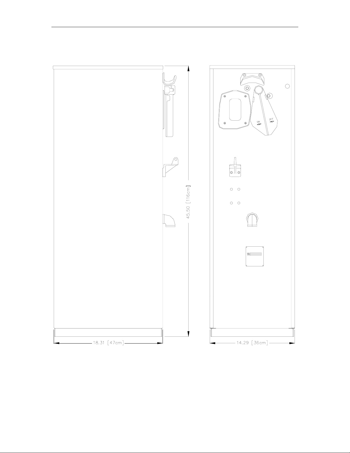
215A/216A SATELLITE DISPENSING UNIT DIMENSIONS
2-4 03/07/03
Page 11

Installation
215A/216A FRONT LOAD SATELLITE DISPENSING UNIT DIMENSIONS
StopStart
1052 2-5
Page 12

GASBOY 215A/215ATW/216A/216ATW Satellite Dispensing Units
215ATW/216ATW TWIN SATELLITE DISPENSING UNIT DIMENSIONS
StopStart
2-6 03/07/03
Page 13

Installation
011975 BASE LAYOUT
Model 215A/216A
1052 2-7
Page 14

GASBOY 215A/215ATW/216A/216ATW Satellite Dispensing Units
011919 BASE LAYOUT
Model 215ATW/216ATW
2-8 03/07/03
Page 15

Section 3
WIRING
☎ Customers and installers having any questions pertaining to the installation should
contact their GASBOY distributor.
WIRING PRECAUTIONS
The quality of the electrical installation is a major factor in maintaining proper safety levels and
providing trouble-free operation of your GASBOY pump/dispenser. To assure a quality
installation, follow these rules:
1. All wiring must be installed to conform with all building/fire codes, all Federal, State, and
Local codes, National Electrical Code, (NFPA 70), NFPA 30, and Automotive and Marine
Service Station Code (NFPA 30A) codes and regulations. Canadian users must also comply
with the Canadian Electrical Code.
2. Use the proper wiring diagram. T his manual contains instructions for wiring mechanical and
electronic units. Using the mechanical wiring diagram for an electronic pump will
cause CPU PCB damage to the electronic pump.
3. Use only threaded, rigid, metal conduit.
4. Use only UL-labeled insulated gasoline- and oil-resistant stranded copper wiring of the proper
size.
5. Wire connections should be tightly spliced and secured with a wire nut; close off the open end
of the wire nut with electrical tape.
6. The line to the motor should be on a separate circuit and installed on a 20 to 30 AMP breaker
depending on the motor size and/or the voltage setting.
7. Install an emergency power cutoff. In addition to circuit breaker requirements of NFPA 70
and NFPA 30A, a single control which simultaneously removes AC power from all site
dispensing equipment is recommended. This control must be readily accessible, clearly
labeled, and in accordance with all local codes.
In a fuel management system application, the EMERGENCY STOP and STOP keys on the
console and/or the optional EMERGENCY STOP button on the Island Card Reader do not
remove AC power from equipment and under certain conditions, will not stop product flow.
In order to provide the highest level of safety to you, your employees, and customers, we
recommend that all employees be trained as to the location and procedure for turning off
power to the entire system.
WARNING:
To reduce the risk of electrical shock when servicing, turn off all power to the
pump/dispenser. In submersible pump applications, turn off power to the submersible
pump and any other dispensers which use that submersible pump. AC power can
feed back into a shut-off dispenser when dispensers share a common submersible
8. Have the pump/dispenser installed by a competent installer/electrician.
pump or starter relay.
03/07/03 3-1
Page 16

GASBOY 215A/215ATW/216A/216ATW Satellite Dispensing Units
GROUNDING
To ensure proper operation of the equipment and provide the necessary safety factors, this unit
must be grounded. A ground wire (preferably green) must be connected between the unit's AC
junction box ground lug and the main electrical service panel. One (1) ear th ground connection is
required per unit. The ground rod is to be a solid, corrosion-resistant conductor and must be
installed at the main electrical panel in accordance with the National Electrical Code. It should be
properly tied into the ground bus strip of the panel. We recommend the neutral and ground bus
strips be bonded together (unless prohibited by local codes).
WIRE SIZE
The minimum AC wire size of the satellite should be 14 AWG.
CONDUIT
All wiring to the satellite dispensing unit must be installed in threaded, rigid, metal conduit. PVC is
not acceptable.
All wiring and conduit runs must also conform with the National Electrical Code (NFPA 70) and the
Automotive and Marine Service Station Code (NFPA 30A). All wiring and conduit runs must
conform to local codes. Canadian users must also comply with the Canadian Electrical Code.
WIRING DIAGRAMS
The following pages contain wiring notes and wiring diagr ams for both 9100A Series mechanical
pumps and 9800A Series electronic pumps. Consult the appropriate wiring diagram for your
pump/dispenser model and follow all notes. Be sure to use the correct wiring diagram.
Incorrect wiring of a 9800A Series unit will cause damage to the CPU PCB.
Wiring diagrams show simultaneous and non-simultaneous operation of master and satellite. Be
sure to use the correct one for your application.
Notes For 024214, 9100A Wiring Diagram:
1. All wiring and conduit runs must conform with all building/fire codes, all F ederal, State, and
Local codes, National Electrical Code, (NFPA 70), NFPA 30, and Automotive and Marine
Service Station Code (NFPA 30A) codes and regulations.
2. See Weights and Measures Handbook 44 to determine which mode of satellite operation is
relevant for your application. In many cases, the satellite must be wired so it cannot dispense
product while the master dispenser is dispensing and vice versa. Use the correct wiring
diagram according to your application.
3. This wiring diagram is intended only to show the connections between the satellite and the
dispenser. See wiring diagram for master dispenser (according to model number) for
applicable warnings and proper connection of all wires. Consult the 9100A Installation
Manual for full wiring information for the dispenser.
4. When wiring dispensers, submersible starter relays are always recommended when a
submersible pump is used; however, the control circuit is capable of directly driving a
submersible pump up to 1 HP at 115/230 VAC. Any pump over these ratings will require a
submersible starter relay.
3-2 03/07/03
Page 17

Wiring
024214 WIRING DIAGRAM
Models Satellite with Island-Oriented Nozzle (side) 215A/9152AX, 9153AX
Satellite with Island-Oriented Nozzle (side) 216A/9153AX, 9140AX
03/07/03 3-3
Page 18

GASBOY 215A/215ATW/216A/216ATW Satellite Dispensing Units
024257 WIRING DIAGRAM
Models Satellite 215A/9800A
Satellite 216A/9800A
NOTES:
1. All wiring and conduit runs must conform with all building/fire codes, all F ederal, State, and
Local codes, National Electrical Code, (NFPA 70), NFPA 30, and Automotive and Marine
Service Station Code (NFPA 30A) codes and regulations. Canadian users must also comply
with the Canadian Electrical Code.
2. See Weights and Measures Handbook 44 to determine which mode of satellite operation is
relevant for your application. In many cases, the satellite must be wired so it cannot dispense
product while the master dispenser is dispensing and vice versa. Use the correct wiring
diagram according to your application.
3. If using a GASBOY 9800A and satellite in an application where both master and satellite
cannot dispense product at the same time, a minor change in the 9800A wiring must be
made. Wire the dispenser to the satellite as shown in the wiring diagram labeled Non-
Simultaneous.
4. If this unit is equipped for 230 VAC operation (international), wire as shown in the standard
115 VAC wiring layout diagram.
5. This wiring diagram is intended only to show the connections between the satellite and the
dispenser. See wiring diagram for master dispenser (according to model number) for
applicable warnings and proper connection of all wires. Consult the 9800A Installation
Manual for full wiring information for the dispenser.
3-4 03/07/03
Page 19

Wiring
03/07/03 3-5
Page 20

GASBOY 215A/215ATW/216A/216ATW Satellite Dispensing Units
024319 WIRING DIAGRAM
Models Satellite 215A/9800A Front Load
Twin Satellite, 215ATW/9800A
Satellite 216A/9800A Front Load
Twin Satellite, 216ATW/9800A
NOTES:
1. All wiring and conduit runs must conform with all building/fire codes, all F ederal, State, and
Local codes, National Electrical Code, (NFPA 70), NFPA 30, and Automotive and Marine
Service Station Code (NFPA 30A) codes and regulations. Canadian users must also comply
with the Canadian Electrical Code.
2. See Weights and Measures Handbook 44 to determine which mode of satellite operation is
relevant for your application. In many cases, the satellite must be wired so it cannot dispense
product while the master dispenser is dispensing and vice versa. Use the correct wiring
diagram according to your application.
3. If using a GASBOY 9800A and satellite in an application where both master and satellite
cannot dispense product at the same time, a minor change in the 9800A wiring must be
made. Wire the dispenser to the satellite as shown in the wiring diagram labeled Non-
Simultaneous.
4. If this unit is equipped for 230 VAC operation (international), wire as shown in the standard
115 VAC wiring layout diagram.
5. Twin satellite models 215ATW and 216ATW: Although the wiring from both master
dispensers will enter into the same AC junction box, the wiring to the controls for each
satellite hose outlet is to be supplied independently from its corresponding master dispenser.
6. This wiring diagram is intended only to show the connections between the satellite and the
dispenser. See wiring diagram for master dispenser (according to model number) for
applicable warnings and proper connection of all wires. Consult the 9800A Installation
Manual for full wiring information for the dispenser.
3-6 03/07/03
Page 21

Wiring
03/07/03 3-7
Page 22

GASBOY 215A/215ATW/216A/216ATW Satellite Dispensing Units
024320 WIRING DIAGRAM
Models Satellite w/Lane-Oriented, Front Load Nozzle 215AZ/9100A
Twin Satellite w/Lane-Oriented, Front Load Nozzle, 215AZTW/9100A
Satellite w/Lane-Oriented, Front Load Nozzle 216AZ/9100A Front Load
Twin Satellite w/Lane-Oriented, Front Load Nozzle, 216AZTW/9100A
NOTES:
1. All wiring and conduit runs must conform with all building/fire codes, all F ederal, State, and
Local codes, National Electrical Code, (NFPA 70), NFPA 30, and Automotive and Marine
Service Station Code (NFPA 30A) codes and regulations.
2. See Weights and Measures Handbook 44 to determine which mode of satellite operation is
relevant for your application. In many cases, the satellite must be wired so it cannot dispense
product while the master dispenser is dispensing and vice versa. Use the correct wiring
diagram according to your application.
3. This wiring diagram is intended only to show the connections between the satellite and the
dispenser. See wiring diagram for master dispenser (according to model number) for
applicable warnings and proper connection of all wires. Consult the 9100A Installation
Manual for full wiring information for the dispenser.
4. When wiring dispensers, submersible starter relays are always recommended when a
submersible pump is used; however, the control circuit is capable of directly driving a
submersible pump up to 1 HP at 115/230 VAC. Any pump over these ratings will requir e a
submersible starter relay.
3-8 03/07/03
Page 23

Wiring
03/07/03 3-9
Page 24

Page 25

Section 4
START-UP
COMPLETION CHECK LIST
The information below should be reviewed to help verify the proper installation of the satellite
dispensing unit. If the installation does not meet criteria listed , correct the problem before
the start-up is performed.
1. If connected to a Series 9800A dispenser, to avoid damage to the CPU PCB board,
verify that the RESET COMPLETE, FAST FLOW, SUBM. STA RTER DRIVE, and SLOW
and FAST SATELLITE RETURN wires are not shorted to conduit or chassis.
2. The unit must be properly secured to the island.
3. All plumbing must be complete and tight. All liquid-carrying lines must be checked for
leaks.
4. All conduit work must be complete. All junction box covers must be secured. Conduits
should not be sealed until the wiring is verified through proper operation.
5. The unit must be properly grounded.
6. Before any testing begins, remove any water in the tank through a fill opening, using a
suitable pump. Do not use the GASBOY pump or dispenser and submersible pump to
remove water. Serious damage may occur.
7. A sufficient volume of fuel must be put in the tank to insure that the liquid level is high enough
to allow the submersible pump to operate efficiently (dispensers).
START-UP
After successfully verifying the installation against the completion check list, the unit is ready for
start-up. Follow the procedure listed below to perform an orderly start-up of the satellite
dispensing unit.
1. Turn on the circuit breaker(s) for the various control lines to the dispenser to be tested.
2. Remove the nozzle for Side 1 from its holder and turn on the pump handle.
3. Dispense fuel. If the unit contains a slow/fast flow valve, verify that it opens. Check all
plumbing for leaks at this time.
4. Turn the pump handle off. Open the nozzle. No fuel should be dispensed.
5. For twin models, repeat Step 1 to Step 4 for the other untested dispenser.
03/07/03 4-1
Page 26

Page 27

Section 5
OPERATING SEQUENCE
1. AC power (115 VAC/230 VAC Int'l) must be provided to the submersible feed and slow
flow/reset motor feed. If a submersible starter relay is used, AC power (115 or 230 VAC)
must be supplied to the input contacts of the submersible starter relay.
2. The user begins to dispense product.
3. At the master dispenser, the register displays the total volume. If an optional pulser kit is
attached, it will be supplying pulses which may be recorded by an external monitoring
system.
4. The fueling transaction continues to run until the user turns off the dispenser handle.
03/07/03 5-1
Page 28

Page 29

Section 6
PREVENTIVE MAINTENANCE
GENERAL
GASBOY dispensers are designed and constructed to give many years of uninterr upted service.
In fact, hundreds of operators report years of trouble-free operation with absolutely no service
expense. Yet, certain parts of a dispenser are bound to wear, and GASBOY therefore
recommends a periodic inspection, at least twice a year. If such a procedure is followed, any
small adjustments that are necessary can be made before expensive, annoying breakdowns
occur. The result of this sound approach is continuous, profitable service from all of your
GASBOY equipment.
Procedures requiring disassembly of portions of the dispenser must be performed by
qualified service personnel.
WARNING:
To reduce the risk of electrical shock when servicing, turn off all power to the
dispenser. In submersible pump applications turn off power to the submersible
pump and any other dispensers which use that submersible pump. AC power can
feed back into a shut-off dispenser when dispensers share a common
submersible pump or starter relay. Always turn off all power to the dispenser and
submerged pumps at the master panel and close any impact valve before
performing any maintenance or service to the dispenser, including the changing of
any fuel filters or strainers. Also block islands so no vehicles can pull up to the
dispenser when the dispenser is being worked on.
HINTS FOR BETTER PUMP PERFORMANCE
Demand Competent Service
If your pump should stop or fail to operate properly, don't depend upon the repair service of a
general mechanic unless he is thoroughly familiar with the mechanism. Experience shows that the
repair results will be much more satisfactory if you demand the service of a competent
representative of the pump manufacturer. GASBOY has a distributor network which services fuel
dispensing and management systems in every section of the country.
Use Authorized Parts
Should excessive wear, rust, or corr osion of parts cause inefficient operation, it is always best to
replace them immediately; but if you want the best results and continuity of the Underwriters' Label
on your pump, be sure they are new authorized service parts supplied by GASBOY. Every part of
a pump or dispenser is carefully designed for a particular purpose. If it is replaced by an incorr ect
or substandard substitute, pump operation will be unsatisfactory. Always use new gaskets or
seals when servicing or rebuilding Gasboy equipment; do not re-use old ones.
03/07/03 6-1
Page 30

GASBOY 215A/215ATW/216A/216ATW Satellite Dispensing Units
Operate with Reasonable Care
Like any machine, the pump or dispenser that is operated with reasonable care will last longer and
give better service. Abuse should be avoided (such as dropping the nozzle on the ground,
operating the unit with a dirty strainer, dragging the hose across the concrete island or driveway,
running the pump with the nozzle closed for more than two minutes, etc.). The time and care
given to your pumps will be returned to you in the form of dependable service.
PREVENTIVE MAINTENANCE CHECK LIST
Keep Water Out
Water tends to collect in underground and above ground storage tanks. This is due to moistureladen air being drawn into the storage tank and condensing, or to defective fill openings that are
not properly protected with watertight covers. Storage tanks should be checked after every fill-up
for water and removed with a sump pump, to forestall serious damage to equipment. Water,
sediment, and other foreign matter that accumulates in the tank can be drawn up into the pump or
dispenser and cause failures.
Preserve the Finish of Your Pumps
Nearly all gasoline pumps are installed outdoors where their surfaces are subjected to the action
of the weather. As a result, it is necessary to give the finish a r easonable amount of care if an
attractive appearance is to be maintained.
The finish on GASBOY pump housings is a high-heat baked synthetic enamel, similar to that used
on automobiles. The life of this finish can be lengthened several years if, at regular intervals, the
painted surfaces are thoroughly cleaned with a high grade automobile polish and then protected
with a coat of paste wax. Do not use abrasive cleaners or polish. Do not use high pressure
spraying equipment.
In order to retain the unmarked finish on stainless steel, occasional cleaning is required. In
corrosive atmospheres, such as coastal areas, a more frequent cleaning schedule is necessary.
Under ordinary conditions, washing with detergent or soap and water, followed by a clean water
rinse, is sufficient. If hard water is used, the surface should be wiped dry with a soft clean cloth to
prevent the formation of water spots. Marks or spots, such as grease, oily fingerprints and
smudges which resist soap and detergents, will have to be removed with a stronger cleaner. (DO
NOT use ordinary steel wool as iron particles may adher e to the surface and cause corrosion.)
Care should be taken in choosing a cleaner because any cleaning compounds or powders which
contain abrasives can scratch a mill-rolled finish. Care must be exercised in their use to run in the
direction of the polishing lines in the steel, never across them. After cleaning, an application of
paste wax is recommended to protect the surface and prolong the interval between cleaning.
6-2 03/07/03
Page 31

GW01 - 6/04/02 Rev. 1
WARRANTY
General Statements:
Gasboy International LLC. warrants all new equipment manufactured by Gasboy agai nst defective materi al and/or workmanship, for the warranty
period specified below, when the equipment i s installed in accordance with specifications prepared by Gas boy.
This warranty does not cover damage caused by acci dent, abuse, Acts of God, lack of surveillance of autom atic recording systems, negligence,
mis-application, faulty installation, i mproper or unauthorized maintenance, i nstallation or use in violati on of product manuals, i nstructions, or warnings.
Under no circumstanc e shall Gasboy be liable for any indirect , special, or consequenti al damages, losses, or expenses to include, but not limited
to, loss of product, los s of profits, litigation fees , or the use, or inability to use, our product for any for any purpose whatsoever.
Parts Only - During the warranty period, Gasboy will, at its option, repair or replace def ective parts returned transportati on prepai d to its factory.
On-Site Labor Included - Gasboy will also provide, within the Continental United St ates and during the warranty period, the services of an
Authorized Service Representati ve (A SR) for on-site repair or replacem ent of defective parts.
Replacement Parts - Any system com ponents that are not part of the origi nal system order, includi ng Island Card Readers, Pump Cont rol Uni ts, etc.,
are considered replacement part s.
Equipment Term Coverage
Commercial Pumps and Dispensers
Full-Cabinet Consumer Pumps
Small Transfer Pumps, Meters,
Pressure Regulators
Keytrol One year from date of instal l ation or 18 mos. from dat e of
Fuel Management Systems :
- CFN/ Profit Point
- Series 1000/Fleetkey
- TopKAT
- Fuel Point Readers
(sold with new systems)
Additional Fuel Point Items:
- Fuel Point Readers sold for
retrofitting existing sys t ems.
- Fuel Point vehicle and dispenser
components.
Encoders, Embos sers, Modems,
CRTs, and Logger Printers
Air Diaphragm Pumps Three years from date of purchas e (for full warranty
Items not m anufactured by Gasboy
(ex. automatic nozzles, hoses, swivels,
etc.)
Replacement Parts One year from date of Gasboy International's invoice to the
To the extent permitted by law, this warranty is made in lieu of all other warranties , express ed or i mplied, including warranties of freedom from patent
infringement, or merchant ability, or fitness for a partic ular purpose, or arising from a course of dealing or usage of trade. No one is authorized to
vary the terms of the warranty nor may anyone make any warranty of representation, or assume any liability other than that herein stated, i n
connection with the sale described herein. The acceptance of any order by Gas boy International is expressly m ade subject to the purchaser' s
agreement to these condit i ons.
One year from date of instal l at i on or 18 mos. from date of
Gasboy International’s invoi ce to the purchaser, whichever
comes first.
One year from date of instal l at i on or 18 mos. from date of
Gasboy International’s invoi ce to the purchaser, whichever
comes first.- Excepting the Model 2020 Hand Pump, which
has a 90-day warranty from date of GASBOY International’s
invoice.
Gasboy International’s invoi ce to the purchaser, whichever
comes first.
One year from date of start-up or 15 mos. from date of
Gasboy International’s invoi ce to the purchaser, whichever
comes first .- The basic warranty only applies to sys tems
which have been started up by a Gasboy Authorized Servi ce
Representative (ASR).
One year from date of start-up or 15 mos. from date of
Gasboy International’s invoi ce to the purchaser,
whichever comes first.
Purchased with Fuel Management Syst em (Encoders,
Embossers only):
90 days from the date of s tart-up by a Gasboy ASR, or 180
days from date of Gasboy I nternational's invoice, whichever
occurs first.
Purchased with Fuel Management System
(Modems, CRTs, and Logger Printers only):
Matches system warranty.
Purchased Separately:
90 days from date of Gasboy I nt ernational's
invoice to the purchaser.
description, see Price List).
Not warranted by Gasboy International (consul t original
manufacturer’s warranty).
purchaser.
Parts and Labor.
Parts Only.
Parts and Labor.
Parts and Labor.
Parts Only.
Purchased with System
(Encoders, Embos sers only):
Parts only.
Purchased with System (Modems,
CRTs, Logger Printers only):
Matches system warranty.
Purchased Separately:
Parts Only.
Parts Only.
Not Applicable.
Parts Only.
GASBOY INTERNATIONAL LLC
P.O. Box 309, Lansdale, PA 19446 ● (800) 444-5579 ● FAX: (800) 444-5569 ● www.gasboy.com
 Loading...