

Page 1

MODELS 2150A, 5200A, 5300A
PARTS MANUAL
035293
REV. 03/07/03
The information in this document is confidential and proprietary. No further disclosure shall be made without
permission from Gasboy International LLC. Gasboy International LLC believes that the information in this document
is accurate and reliable. However, we assume no responsibility for its use, nor for any infringements of patents or
other rights of third parties resulting from its use. We reserve the right to make changes at any time without notice.
Copyright 2003 by Gasboy International LLC All rights reserved.
GASBOY INTERNATIONAL LLC LANSDALE, PA
Page 2

Gasoline and petroleum products are flammable. To avoid injury or death to persons or damage to equipment or
property, follow these listed warnings and other warnings and precautions outlined in this manual when installing, using,
or working around this equipment. Check with GASBOY Technical Services for compatibility of liquids with pump
materials.
TURN OFF AND LOCK OUT ALL POWER TO PUMP BEFORE PERFORMING SERVICE, MAINTENANCE OR IN THE EVENT
All products must be installed by a
qualified installer and used in
conformance with all building, fire, and
environmental codes and other safety
requirements applicable to its
installation and use, including, but not
limited to, NFPA 30, NFPA 30A, NFPA
395 & NFPA 70. A qualified installer is
familiar with fuel systems installations
under the above stated building, fire,
and environmental codes and other
safety requirements for the particular
type of installation.
This product is only part of a fuel
dispensing system and additional
equipment and accessories, such as,
but not limited to, breakaway
connectors, shear valves, pressure
regulators, flow limiters, and other
safety devices may be necessary to
meet the applicable codes.
For maximum safety, we recommend
that all employees be trained as to the
location and procedure for turning off
power to th e e nti re syst em. Inst ruct ion s
regarding proper operation of the
equipment along with the appropriate
safety warnings should be posted in
plain view at the fuel island.
Before performing service or
maintenance (including changing of fuel
filters or strainers) or in the event of a
fuel spill, turn off and lock out all power
to the system. In battery-powered
pumps, disconnect power source. In
submersible pump applications, turn off
and lock out power at the master panel
and close any impact valves to the
submersible pump and any other
dispensers which use that submersible
pump. AC power can feed back into a
shut-off dispenser when dispensers
share a common submersible pump or
starter relay. Also block islands so no
vehicles can pull up to the dispenser
when the dispenser is being worked on.
IMPORTANT WARNINGS AND SAFEGUARDS
OF A FUEL SPILL.
DO NOT use Teflon tape for any pipe
threads in the product.
DO NOT use consumer pumps for
pumping fuel or additives into aircraft.
DO NOT use commercial pumps for
direct fueling of aircraft without filters
and separators necessary to ensure
product purity.
DO NOT use where sanitary design is
required (for food products for human
consumption) or with water-based
liquids.
DO NOT smoke near the pump or when
using the pump.
DO NOT use near open flame or
electrical equipment which may ignite
fumes.
DO NOT permit the dispensing of
gasoline or other petroleum products
into a vehicle with its motor running.
DO NOT permit the dispensing of
gasoline or other petroleum products
into unapproved containers or into
approved containers in or on vehicles
includin g tru cks. All conta iner s must be
filled on the ground to prevent static
discharge. Always use Approved and
Listed hoses and nozzles with electric
pumps and dispensers.
DO NOT block open the nozzle in any
manner. Nozzles shall conform to UL
and NFPA code requirements for
attended or unattended service.
DO ensure that the pump is equipped
with proper filters based on the product
being dispensed and its intended use.
DO wear safety goggles and protective
clothes when dispensing any liquid
which may be potentially harmful or
hazardous.
DO keep all parts of body and loose
clothing clear of belts, pulleys, and
other exposed moving parts at all times.
DO require washing and changing of
clothes if fuel is spilled on a person or
his/her clothing. Keep away from open
flames, sparks, or people smoking.
DO provide a receptacle for catching
product from pump/meter when
servicing.
DO clean up product spills on the
driveway. Turn off and lock out all
power prior to cleanup.
DO insure pump is properly grounded.
DO insure hose is compatible with fluid
being dispensed.
DO inspect hose, nozzle, and pump on
a regular basis for wear, damage, or
other conditions which may create a
safety or environmental hazard.
DO make sure all pipe threads are
properly cut and the inside reamed to
remove burrs. Use UL classified
gasoline-resisting compound on all
joints of gasoline handling piping.
Sealing compound must also be
resistant to Gasohol (Ethanol and
Methanol). Use gasoline-resistant pipe
compound on male threads only; pipe
compound used on female threads can
be squeezed into the supply line where
it can enter the product stream and
become lodged in the pump or meter.
DO ensure that junction box covers are
in place and properly tightened. Mating
surfaces between the box and cover
must be free of dirt, nicks, and
scratches. All unused entries into the
junction box must be properly plugged.
035282 Rev. 1267
GASBOY INTERNATIONAL, LLC.
707 North Valley Forge Rd. Lansdale, PA, 19446 ● (215) 855-4631 ● FAX: (215) 855-0341
Page 3

CONTENTS
Warnings and Safeguards
General..................................................................................................................................... 1
2150A, 5200A, 5300A Final Assembly - Front View ................................................................ 2
2150A, 5200A, 5300A Final Assembly - Side View.................................................................. 4
2150ARDX-1 Chassis - Front View.......................................................................................... 6
2150ARDX-1 Chassis - Side View........................................................................................... 8
2150ARDX-2 Chassis - Front View.......................................................................................... 10
2150ARDX-2 Chassis - Side View........................................................................................... 12
5200A-2, 5300A-2 Chassis - Front View.................................................................................. 14
5200A-2, 5300A-2 Chassis - Side View ................................................................................... 16
2150A Discharge Assembly - 024379...................................................................................... 18
2150A Satellite Discharge Assembly - 045641 ........................................................................ 18
5200A Discharge Assembly - 024375; 5300A Discharge Assembly - 024376 ........................ 19
5200A-1 & 5300A-1 Inlet Manifold Assembly - 035194............................................................ 19
Flange Assembly...................................................................................................................... 20
Electric Reset - S00206............................................................................................................ 21
Pumping Unit Assembly Breakdown........................................................................................ 22
Meter Assembly Breakdown..................................................................................................... 24
Motor Mount Detail................................................................................................................... 26
Strainer Body Assembly........................................................................................................... 26
03/07/03 Contents-1
Page 4

Page 5

PARTS LIST
GENERAL
This manual lists parts information for the Model 2150A, 5200A and 5300A pumps and
dispensers. Using part numbers when ordering will expedite your order and reduce the possibility
of the wrong parts being shipped. When ordering r eplacement parts, be sure to give the complete
name and part number as shown in the appropriate parts lists. It is also helpful to supply the serial
number of the equipment.
This manual is arranged from general to specific, presenting the complete unit first, then the
chassis breakdowns, then further breakdowns of the individual components. If you can’t find the
part you need from the chassis drawing, be sure to check the appropriate parts breakdown for
your model.
03/07/03 1
Page 6
GASBOY Series 2150A, 5200A & 5300A
2150A, 5200A, 5300A FINAL ASSEMBLY - FRONT VIEW
2 03/07/03
Page 7

Parts
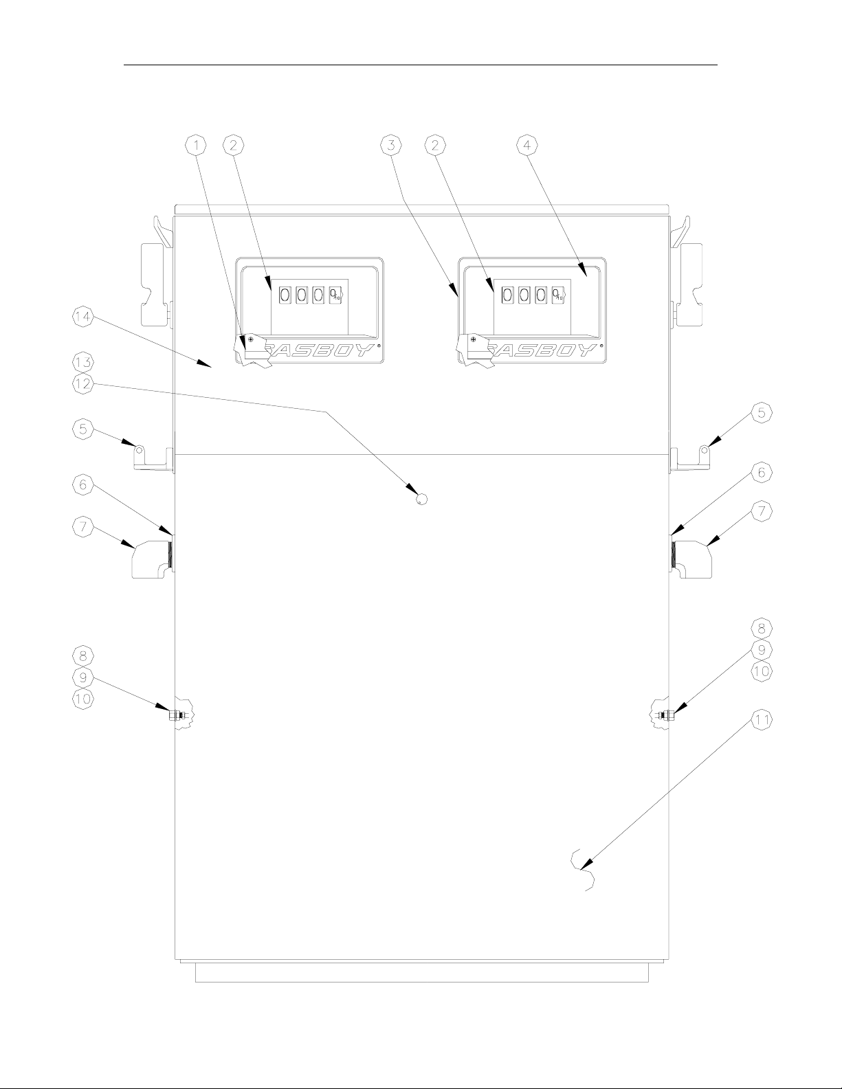
2150A, 5200A, 5300A FINAL ASSEMBLY - FRONT VIEW
Item Part No. Description
1 025527 Dial Face, Non-Totalizer
025542 Dial Face, Total Gallons
2 Dial Enclosure (Part no longer available)
3 012252 Bezel Assy.
4 069050 Window Glass
5 003745 Nozzle Hook
6 028960 Grommet
7 003620 Elbow, Discharge
8 026047 Fitting, 3/8 Ct Conn Inv Fl
9 067885 Washer, Fiber, 1/2 x 3/4 x 1/16
10 017921 Cap, Vent
11 Lower Panel Assy., CRS (Part no longer available)
Lower Panel Assy., SS (Part no longer available)
12 026799 Gasket, Lock
13 035012 Lock, Door
14 Upper Panel Assy., CRS (Part no longer available)
Upper Panel Assy., SS (Part no longer available)
03/07/03 3
Page 8

GASBOY Series 2150A, 5200A & 5300A
2150, 5200A, 5300A FINAL ASSEMBLY - SIDE VIEW
4 03/07/03
Page 9

Parts
2150, 5200A, 5300A FINAL ASSEMBLY - SIDE VIEW
Item Part No. Description
1 003744 Hose Hook
2 033831 Control Lever
3 043105 Pin
4 Scuff Panel (Part no longer available)
5 Side Panel Weld Assy., CRS (Part no longer available)
Side Panel Weld Assy., SS (Part no longer available)
Side Panel Assy., Int. Retriever, CRS (Part no longer available)
Side Panel Assy., Int. Retriever, SS (Part no longer available)
6 046765 Plate, Nozzle Backup
7 003332 Boot, Nozzle
8 Top Cover Assy., CRS (Part no longer available)
Top Cover Assy., SS (Part no longer available)
NOTE: Pumps equipped with internal retrievers use the following parts (not shown):
Internal Retriever Parts - 047946
Item Part No. Description
1 040035 Cable Guide, Internal Hose Retriever
2 020712 Clamp, 1" Hose
3 048369 Reel and Cable
4 015022 Bracket, Internal Hose Retriever
03/07/03 5
Page 10
GASBOY Series 2150A, 5200A & 5300A
2150ARDX-1 CHASSIS - FRONT VIEW
6 03/07/03
Page 11

Parts
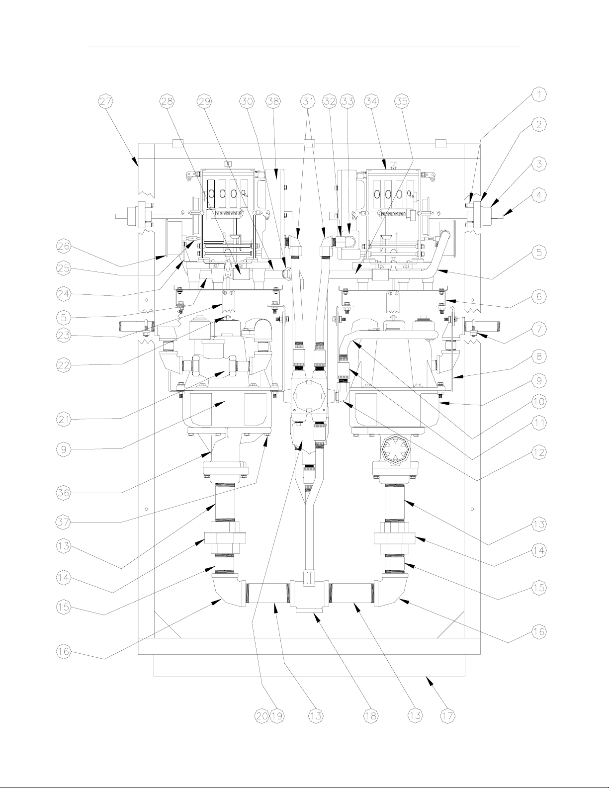
2150ARDX-1 CHASSIS - FRONT VIEW
Item Part No. Description
1 063215 Stop, Operating Shaft
2 015546 Bracket & Spring Assy.
3 003185 Bearing, Start Shaft
4 055675 Shaft, Start Assy.
5 021651 Conduit, Pulser
6 063963 Support, Computer
7 013295 U-Bolt, 1-3/8 ID
8 015043 Bracket, Meter Support, Non-Computer
9 035517 Meter, Gallons
035576 Meter, Liters
10 021648 Conduit, 1" ITT Valve
11 066400 Union, Explosion-Proof Conduit
12 025045 Elbow
13 044933 Pipe, TBE, 1-1/2 x 4-3/4
14 066385 Union, 1-1/2 Stockham #150
15 038005 Pipe, TBE, 1-1/2 x 1-3/4
16 Z03555 Elbow, 1-1/2 x 90
17 011680 Base Assy.
18 064811 Tee, Reducing 1-1/2 x 1-1/2 x 2
19 003337 Box, Junction
20 003461 Cover, Junction Box
21 024379 Discharge Pipe/Valve Assy.(See Breakdown)
045641 Satellite Piping Assembly (See Breakdown)
22 042595 Pin, Drive-Lock, 1/8 x 5/8
23 021978 Coupling Half
24 015431 Bracket, Pulser, Gallon
25 021941 Coupling, Pulser
26 021788 Pulser, 10:1
047648 Pulser, 100:1
27 026656 Frame
28 021986 Coupling, 1/2 Conduit
29 021652 Conduit, Pulser
30 025030 Elbow, Conduit 1/2 x 90
31 021685 Conduit & Electrical
32 024917 Potted Elbow
33 048370 Reducer, Conduit
34 021222 Non-Computer Assy., Electric Reset, w/o Top Drive, Gallons
*020996 Non-Computer Assy. w/o Electric Reset
021107 Non-Computer Assy., Electric Reset, w/o Top Drive, Liters
35 021650 Conduit, Pulser
36 Strainer Body Assy. (See breakdown Strainer Body Assembly)
37 052020 Screw, 3/8-16 x 1-1/4, HHC, GR-5
38 Electric Reset only (See Breakdown)
*Denotes this is a subpart used in the preceding assembly
o
o
F/F
03/07/03 7
Page 12

GASBOY Series 2150A, 5200A & 5300A
2150ARDX-1 CHASSIS - SIDE VIEW
8 03/07/03
Page 13

Parts
2150ARDX-1 CHASSIS - SIDE VIEW
Item Part No. Description
1 015000 Bracket, Junction Box
2 021685 Conduit & Electrical
3 066400 Union, Explosion-Proof Conduit
4 027038 Gasket
5 003344 Junction Box
6 022140 Junction Box Cover Assy.
7 Check Valve Assy. (See breakdown Strainer Body Assembly)
8 048138 Valve Housing
9 021162 Conduit
10 021986 Conduit Coupling
11 021380 Conduit, 1/2 x 7-1/2
03/07/03 9
Page 14

GASBOY Series 2150A, 5200A & 5300A
2150ARDX-2 CHASSIS - FRONT VIEW
10 03/07/03
Page 15

Parts
2150ARDX-2 CHASSIS - FRONT VIEW
Item Part No. Description
1 063215 Stop, Operating Shaft
2 015546 Bracket & Spring Assy.
3 003185 Bearing, Start Shaft
4 055675 Shaft, Start Assy.
5 021651 Conduit, Pulser
6 063963 Support, Computer
7 013295 U-Bolt, 1-3/8 ID
8 015043 Bracket, Meter Support, Non-Computer
9 035517 Meter, Gallons
035576 Meter, Liters
10 021648 Conduit, 1" ITT Valve
11 066400 Union, Explosion-Proof Conduit
12 025045 Elbow
13 044903 Pipe, TBE 1-1/2 x 9-1/4
14 066385 Union, 1-1/2 Stockham #150
15 003337 Box, Junction
16 003461 Cover, Junction Box
17 024379 Discharge Pipe/Valve Assy.(See Breakdown)
045641 Satellite Piping Assembly (See Breakdown)
18 042595 Pin, Drive-Lock, 1/8 x 5/8
19 021978 Coupling Half
20 015431 Bracket, Pulser, Gallon
21 021941 Coupling, Pulser
22 021788 Pulser, 10:1
047648 Pulser, 100:1
23 026656 Frame
24 021986 Conduit Coupling
25 021652 Conduit, Pulser
26 025030 Elbow, Conduit 1/2 x 90
27 021685 Conduit & Electrical
28 024917 Potted Elbow
29 048370 Reducer, Conduit
30 021222 Non-Computer Assy., ERS, w/o Top Drive, Gallons
*020996 Non-Computer Assy. w/o Electric Reset
021107 Non-Computer Assy., ERS, w/o Top Drive, Liters
31 021650 Conduit, Pulser
32 Strainer Body Assy. (See breakdown Strainer Body Assembly)
33 052020 Screw, 3/8-16 x 1-1/4, HHC, GR-5
34 Electric Reset only (See Breakdown)
*Denotes this is a subpart used in the preceding assembly
o
F/F
03/07/03 11
Page 16

GASBOY Series 2150A, 5200A & 5300A
2150ARDX-2 CHASSIS - SIDE VIEW
12 03/07/03
Page 17

Parts
2150ARDX-2 CHASSIS - SIDE VIEW
Item Part No. Description
1 015000 Bracket, Junction Box
2 021685 Conduit & Electrical
3 066400 Union, Explosion-Proof Conduit
4 027038 Gasket
5 003344 Junction Box
6 022140 Junction Box Cover Assy.
7 Check Valve Assy. (See breakdown Strainer Body Assembly)
8 048138 Valve Housing
9 021162 Conduit
10 021986 Conduit Coupling
11 021380 Conduit, 1/2 x 7-1/2
03/07/03 13
Page 18

GASBOY Series 2150A, 5200A & 5300A
5200A-2, 5300A-2 CHASSIS - FRONT VIEW
14 03/07/03
Page 19

Parts
5200A-2, 5300A-2 CHASSIS - FRONT VIEW
Item Part No. Description
1 021222 Non-Computer Assy., ERS,
w/o Top Drive, Gallons
*020996 Non-Computer Assy. w/o
Electric Reset
021107 Non-Computer Assy., ERS,
w/o Top Drive, Liters
2 021651 Conduit, Pulser
3 021986 Conduit Coupling
4 025030 Elbow, Conduit 1/2 x 90o F/F
5 025045 Elbow
6 021685 Conduit & Electrical
7 024917 Potted Elbow
8 048370 Reducer, Conduit
9 021650 Conduit, Pulser
10 021788 Pulser, 10:1
047648 Pulser, 100:1
11 063215 Stop, Operating Shaft
12 015546 Bracket & Spring Assy.
13 003185 Bearing, Start Shaft
14 055675 Shaft, Start Assy.
15 063963 Support, Computer
16 013295 U-Bolt, 1-3/8 ID
17 024375 Discharge Piping Assy., 3/4"
Twin Pump, 5200
024376 Discharge Piping Assy., 1"
Pump Twin, 5300
18 015043 Bracket, Meter Support, Non-
Computer
19 035528 Meter Assy., Gallons
*035517 Meter, Gallons
*035513 Meter Transfer Body
*027038 Gasket
*052020 Screw, 3/8-16 x 1-1/4 HHC,
GR-5
035535 Meter Assy., Liters
*035576 Meter, Liters
*035513 Meter Transfer Body
*027038 Gasket
*052020 Screw, 3/8-16 x 1-1/4 HHC,
GR-5
Item Part No. Description
20 065830 Tube Assy, Vent
21 021972 Coupling Nipple
22 047680 Pulley, Variable Pitch
23 012143 Belt, Vee 30 4L300
24 031315 Key
25 047598 Pump, Pulley
26 066385 Union, 1-1/2 Stockham #150
27 038005 Pipe, TBE 1-1/2 x 1-3/4 Close
28 047075 Platform, Motor
29 025015 Elbow, Conduit, 1/2 x 45o M/F
30 014141 Box, Junction
31 022196 Cover, Junction Box
32 021666 Conduit
33 066400 Union, Explosion-Proof
Conduit
34 003337 Box, Junction
35 003461 Cover, Junction Box
36 037667 Motor, 1/3 HP, 60 Hz. w/o
switch, 5200
037692 Motor, 3/4 HP, 60 Hz.w/o
switch, 5300
NOTE: Motor must be A.O. Smith;
Franklin cannot be substituted.
37 048028 Pumping Unit, 5200
048022 Pumping Unit, 5300
(See Breakdown)
38 Flange Assy. (See Breakdown)
39 021377 Conduit, 1/2 x 6
40 021518 Conduit, 1/2 x 11-1/2
41 021652 Conduit, Pulser
42 021977 Coupling Half
43 015431 Bracket, Pulser, Gallon
44 021941 Coupling, Pulser
45 026652 Frame
46 Electric Reset only (See
Breakdown)
*Denotes this is a subpart used in the preceding
assembly
03/07/03 15
Page 20

GASBOY Series 2150A, 5200A & 5300A
5200A-2, 5300A-2 CHASSIS - SIDE VIEW
16 03/07/03
Page 21

Parts
5200A-2, 5300A-2 CHASSIS - SIDE VIEW
Item Part No. Description
1 066400 Union, Explosion-Proof Conduit
2 021986 Coupling, 1/2 Conduit
3 021364 Conduit, 1/2 x 3-1/2
4 038050 Conduit, 1/2 x 1-3/16 Close
5 025030 Elbow, Conduit 1/2 x 90
6 021664 Conduit, Bent, 3-7/8 x 3-7/8
7 021456 Conduit, 1/2 x 4-1/4
8 025045 Elbow
9 038050 Conduit, 1/2 x 1-3/16 Close
10 C08125 Conduit, Fitting 1/2 Union F/F
11 021663 Conduit
12 021345 Conduit, 1/2 x 1-1/2
13 021294 Conduit, 1/2 x 8
14 064840 Tee, Conduit
15 048370 Reducer, Conduit
o
F/F
03/07/03 17
Page 22

GASBOY Series 2150A, 5200A & 5300A
2150A DISCHARGE ASSEMBLY - 024379
Item Part No. Description
1 003582 Elbow, Flanged Meter Discharge
2 024941 Elbow, 1 x 90
3 038035 Pipe, TBE, 1 x 1-1/2 Close Nip
4 024895 Elbow, 1 x 90
5 067035 Valve, Solenoid, 1" Skinner
NOTE: This part replaces part 067021
which is no longer available. It
requires field modification of
conduit for installation.
6 044550 Pipe, TBE, 1 x 3-1/2
o
, Street
o
, Std.
2150A SATELLITE DISCHARGE ASSEMBLY - 045641
Item Part No. Description
1 003582 Elbow, Flanged Meter Dschg
2 024941 Elbow, 1 x 90o, Street
3 038035 Pipe, TBE, 1 x 1-1/2 Close Nip
4 064796 Tee, 1 x 1 x 1
5 044665 Pipe, TBE 1 x 12
6 021984 Pipe Coupling, Reducer, 1-1/2 x 1
7 044921 Pipe, TBE, 1-1/2 x 7
8 066385 Union, 1-1/2 Stockham #150
9 067035 Valve, Solenoid, 1" Skinner
(See NOTE above)
10 024895 Elbow, 1 x 90o, Std.
11 044550 Pipe, TBE, 1 x 3-1/2
18 03/07/03
Page 23

Parts
5200A DISCHARGE ASSEMBLY - 024375
5300A DISCHARGE ASSEMBLY - 024376
Item Part No. Description
1 044159 Pipe, TBE, 3/4 x 15-1/2, 5200
044664 Pipe TBE, 1 x 11-7/8, 5300
2 003581 Elbow, Flanged Meter Discharge, 5200
003582 Elbow, Flanged Meter Discharge, 5300
3 024940 Elbow, Street, 3/4 x 9 Obl, 5200
024941 Elbow, 1 x 90
o
, Street, 5300
5200A-1 & 5300A-1 INLET MANIFOLD ASSEMBLY - 035194
Item Part No. Description
1 064797 Tee, 1-1/2
2 045487 Pipe TOE, 1-1/2 x 3-3/8
3 022046 Ell, Dresser, 1-1/2 x 90
4 066804 Check Valve Assy.
5 044910 Pipe, TBE, 1-1/2 x 2-1/2
6 024926 Pipe Return Bend 1-1/2
7 038005 Pipe, TBE, 1-1/2 x 1-3/4
8 066385 Union, 1-1/2 Stockham #150
NOTE: Items 5 and 6 must be ordered separately. They are not part of assembly 035194.
o
03/07/03 19
Page 24

GASBOY Series 2150A, 5200A & 5300A
FLANGE ASSEMBLY
Item Part No. Description
1 049014 O-Ring
M49014 O-Ring, Methanol/Ethanol
2 026079 Flange
3 051950 5/16-18 x 1-3/4 HHC Screw
4 068005 1/4 Washer
5 068875 Lockwasher, 5/16
6 027797 Gasket
7 021950 Coupling
20 03/07/03
Page 25

Parts
ELECTRIC RESET - S00206
Item Part No. Description
1 S00211 Reset Motor, 115V
S00212 Reset Motor, 220V
2 S00208 Electric Reset Motor Switch
3 S55321 Shaft, Ctr, Non-Computer (not visible on illustration)
4 S00213 Cam Group, Clockwise
5 S00210 Switch, DPDT, Robertshaw
03/07/03 21
Page 26

GASBOY Series 2150A, 5200A & 5300A
PUMPING UNIT ASSEMBLY BREAKDOWN
22 03/07/03
Page 27

Parts
PUMPING UNIT ASSEMBLY BREAKDOWN
Item Part No. Description
1 S00117 Gasket
2 S00456 Float Lever Pin
3 S00066 Valve Pin
4 S00067 Guide Plate
5 S00068 Spring Plate
6 S00069 Plunger Head
7 S00072 Plunger Plate
8 S00073 Plunger Follower
9 S00074 Valve Cylinder
10 S00075 Cylinder Head
11 S00076 Clamp Plate
12 S00077 Float Valve Body
13 S00078 By-Pass Valve Spring (#34 to
S00079 By-Pass Valve Spring (44-1/2#
14 S00080 Vent Screw
15 S00062 Valve Cylinder Gasket
16 S00081 Vent Screw Guard
17 S00082 Float Valve Needle
18 S00083 Float Valve Gasket
19 S00128 Pump Rotor Shaft Assembly
20 S00119 Bottom Head Gasket
21 S00084 Separator Cover
22 S00120 Cover Gasket
23 S00085 Retainer
24 S00121 Bearing
25 S00086 Regulating Poppet Assy
26 S00124 Oil Well Felt
27 S00061 Float Assembly
29 S00718 Gasket
30 063312 Suction Screen (Gasoline, 100
063313 Suction Screen (Diesel, 40
31 S00088 Regulating Valve Spring
32 S00089 By-pass Valve Poppet
33 S00056 Packing Gland
34 S00090 Packing Spring
35 S00091 Rotary Pump & Separator
36 S00092 Regulating Valve Seat
37 S00093 Valve Seat Guide
38 S00094 By-pass Valve Seat
39 S00717 Check Valve Cap
41 S00447 Poppet Spring
43 S00116 "V" Packing
44 S00095 Plunger Guide
45 S00096 Plunger Disc
46 S00097 Plunger Spacer
47 S00122 Drive Shaft Bearing
48 S00129 Rotary Pump Idler
50 S00098 Poppet Disc. & Relief Valve
52 063261 Suction Strainer Cap
35-1/2# spring (52)
Spring (53)
mesh)
mesh)
Body w/Gasket, Bearing,
Screws & Spring
Assy
Item Part No. Description
53 S00125 By-pass Valve Assembly (34#
to 35-1/2# spring (52)
S00126 By-pass Valve Assembly (44-
1/2# spring (53)
54 S00127 Regulating Valve Assembly
55 026768 Gasket
56 S00451 1/4-20 x 7/8 Lg. Rd. Hd. Mach
Screw
57 S00452 1/4-20 x 1/2 Lg. Hex Hd. Cap
Screw
58 S00453 5/16-18 x 7/8 Lg. Hex. Hd. Cap
Screw
59 S00454 3/8-16 x 2-3/4 Lg. Hex. Hd.
Cap Screw
60 S00455 3/8-16 x 1-1/8 Lg. Hex. Hd.
Cap Screw
62 S00457 1/16 x 1/2 Lg. Cotter Pin
63 S00459 1/4 Sq. Hd. Pipe Plug
65 S00461 1/4 - 28 Hex. Nut
67 S01135 Lower Pump Head w/Valve
Seat Guides, Regulating Valve
Seat & By-pass Valve Seat
68 S00057 Rotary Pump Head Assembly
03/07/03 23
Page 28

GASBOY Series 2150A, 5200A & 5300A
METER ASSEMBLY BREAKDOWN
24 03/07/03
Page 29

Parts
METER ASSEMBLY BREAKDOWN
Item Part No. Description
1 S00466 Packing Gland Plate
2 S00467 Seal Pin
3 S00469 Compensator Screw Spring
4 S00473 Drive Shaft
5 069080 Seal & Seal Wire
6 S00475 Special Screw
7 S00476 Drive Shaft Pin
8 S00477 1/2" Ball
9 S00480 Plunger Cup Support
10 S00481 Plunger Disc
11 S00182 Washer
12 S00183 Washer
13 S00484 Upper Bearing Assembly
14 S00485 Bearing Assembly
15 S00487 Compensator Index Disc
16 S00488 Seal Half
17 S00489 Seal Wedge
18 S00490 Washer
19 S00492 Packing Spring
20 S00493 Seal
23 S00494 Bearing Retainer
24 S00495 Seal (black)
25 S00491 Seal Retaining Ring
26 S00478 Compensator Pinion
27 S00512 Screw
28 S00498 Main Pivot Bracket Assembly
w/ Pins
29 S00032 Plunger Cup Kit (Set of 3
Cups)
30 S00501 Valve
31 S00502 Wobble Plate w/ Slack Roller
Post
32 S00503 Connector
33 S00504 Bearing Seat
35 S00505 Slack Roller Assembly
36 S00506 Slack Spring Assembly
37 S00496 Drive Shaft Gear - Gal
S00115 Drive Shaft Gear - Ltr
Item Part No. Description
38 S00499 Counter Drive Gear Complete -
Gal
S00114 Counter Drive Gear Complete -
Ltr
39 S00497 Compensator Shaft
40 S00500 Bracket & Pin Assembly
41 S00468 Index Plate
42 S00479 Pivot & Ball Assembly
43 S00470 Meter Body Gasket
44 S00471 "O" Ring (.362 Dia.)
45 S00472 "O" Ring (.487 Dia)
46 S00486 Meter Cover w/ Center Gear
Post, Index Plate, Pipe Plug &
Retaining Ring
47 S00509 #10-32 x 3/8 Lg. Rd. Hd. Mach.
Screw
48 S00507 #12-24 x 1/2 Lg. Rd. Hd. Mach.
Screw
49 S00508 1/4-20 x 3/4 Lg. Rd. Hd. Mach.
Screw
50 S00511 1/4-20 Hex Nut
51 S00510 5/16-18 Hex Nut
52 S00520 1/4 Lockwasher
53 S00513 #1212 Lockwasher
54 S00514 #1114 Lockwasher
55 S00515 1/8 Sq. Hd. Pipe Plug
56 S00516 #10-32 x 3/8 Lg. Rd. Hd. Sems
Fastener
57 S00517 1/16 x 1/4 Lg. Cotter Pin
58 S00518 Truarc Retaining Ring
59 S00519 Truarc "E" Retaining Ring
60 S00521 Plunger Assy. w/ Bearing
Retainer, Bearing Seat & Sems
Fastener
61 S00522 Body & Seat Assembly w/ Pins
03/07/03 25
Page 30

GASBOY Series 2150A, 5200A & 5300A
MOTOR MOUNT DETAIL
Item Part No. Description
1 051940 5/16-18 x 1-1/2 HHC Screw
2 068080 5/16 Washer
3 067735 Cup Washer
4 068620 Washer
5 038920 5/16-18 ESNA Nut
6 037885 Rubber Mount
STRAINER BODY ASSEMBLY
Item Part No. Description
1 063261 Strainer Cap
2 063312 Gasoline Strainer (100 mesh)
063313 Diesel Strainer (40 mesh)
3 S00524 Strainer Body
4 026768 O-Ring
5 027005 Gasket
6 035319 Check Valve Assy.
26 03/07/03
Page 31

GW01 - 6/04/02 Rev. 1
WARRANTY
General Statements:
Gasboy International LLC. warrants all new equipment manufactured by Gasboy against defective material and/or workmanship, for the warranty
period specified below, when the equipment i s installed in accordance with specifications prepared by Gasboy.
This warranty does not cover damage caused by acci dent, abuse, Acts of God, lack of surveillance of automatic recording systems, negl i gence,
mis-application, faulty installation, i mproper or unauthorized maintenance, i nstallation or use in violati on of product manuals, instructions, or warnings.
Under no circumstanc e shall Gasboy be liable for any indirect , special, or consequential damages, losses, or expenses t o i nclude, but not limit ed
to, loss of product, los s of profits, litigation fees, or the use, or inability to use, our product f or any f or any purpos e whatsoever.
Parts Only - During the warranty period, Gasboy will, at its option, repair or replace defective parts returned transportati on prepai d to its factory.
On-Site Labor Included - Gasboy will also provide, within the Continental United States and during the warranty period, the services of an
Authorized Service Representati ve (A S R) for on-site repair or replacement of defective parts.
Replacement Parts - A ny system component s that are not part of the original system order, including Island Card Readers, Pump Control Uni ts, etc.,
are considered replacement part s.
Equipment Term Coverage
Commercial Pumps and Dispensers
Full-Cabinet Consumer Pum ps
Small Transfer Pumps, Meters,
Pressure Regulators
Keytrol One year from date of instal l ation or 18 mos. from date of
Fuel Management Systems :
- CFN/ Profit Point
- Series 1000/Fleetkey
- TopKAT
- Fuel Point Readers
(sold with new systems)
Additional Fuel Point Items:
- Fuel Point Readers sold for
retrofitting existing systems.
- Fuel Point vehicle and dispenser
components.
Encoders, Embos sers, Modems,
CRTs, and Logger Printers
Air Diaphragm Pumps Three years from date of purchas e (for full warranty
Items not m anufactured by Gasboy
(ex. automatic nozzles, hoses, swivels,
etc.)
Replacement Parts One year from date of Gasboy International's invoice to the
To the extent permitted by law, this warranty is made in lieu of all other warranties, expressed or implied, includi ng warranties of freedom from patent
infringement, or merchant abilit y, or fitness for a particular purpose, or arising from a course of dealing or usage of t rade. No one i s authorized to
vary the terms of the warranty nor may anyone make any warranty of representation, or assum e any liabilit y ot her t han that herein stated, in
connection with the sale desc ri bed herei n. The acceptance of any order by Gasboy Int ernational is expressly made subject to the purchaser's
agreement to these condit i ons.
One year from date of install ation or 18 mos. from date of
Gasboy International’s invoi ce to the purchaser, whichever
comes first.
One year from date of install ation or 18 mos. from date of
Gasboy International’s invoi ce to the purchaser, whichever
comes first.- Excepting the Model 2020 Hand Pump, which
has a 90-day warranty from date of GASBOY International’s
invoice.
Gasboy International’s invoi ce to the purchaser, whichever
comes first.
One year from date of start-up or 15 mos. from date of
Gasboy International’s invoi ce to the purchaser, whichever
comes first .- The basic warranty only applies to sys tems
which have been started up by a Gasboy Authorized Service
Representative (ASR).
One year from date of start-up or 15 mos. from date of
Gasboy International’s invoi ce to the purchaser,
whichever comes first.
Purchased with Fuel Management Syst em (Encoders,
Embossers only):
90 days from the date of s t art-up by a Gasboy ASR, or 180
days from date of Gasboy I nternational's invoice, whichever
occurs first.
Purchased with Fuel Management System
(Modems, CRTs, and Logger Printers only):
Matches system warranty.
Purchased Separately:
90 days from date of Gasboy International's
invoice to the purchaser.
description, see Price List).
Not warranted by Gasboy International (consul t original
manufacturer’s warranty).
purchaser.
Parts and Labor.
Parts Only.
Parts and Labor.
Parts and Labor.
Parts Only.
Purchased with System
(Encoders, Embos sers only):
Parts only.
Purchased with System (Modems,
CRTs, Logger Printers only):
Matches system warranty.
Purchased Separately:
Parts Only.
Parts Only.
Not Applicable.
Parts Only.
GASBOY INTERNATIONAL LLC
P.O. Box 309, Lansdale, PA 19446 ● (800) 444-5579 ● FAX: (800) 444-5569 ● www.gasboy.com
 Loading...