

Gasboy 120VAC User Manual
INSTRUCTIONS FOR
120 VAC (C06480/C07191) AND 240 VAC (C06507/C07192) FLUORESCENT LIGHT KITS
Locate and identify the following parts in the Light Kit. Hardware and quantities may vary.
QTY PART NO. DESCRIPTION
1 C06437 Cable Assy., Ballast 120 VAC or
C06476 Cable Assy., Ballast 240 VAC
2 C06398 Cable Assy., Display Panel Lights
or
2 C07117 Cable Assy., Display Panel Lights
2 033412 Lamp, Fluorescent F15T8/CW
2 Z09273 Nut, 10-32
10 053737 Screw, #8-32 x 3/8 TT
2 068891 Ext. Star Lock Washer
2 067765 Small #8 Flat Washer
1. Installing this kit involves wiring to the breaker panel. Read Sections 3 and 4 of the
before proceeding.
2. Turn off the circuit breakers supplying power to the MICRO, LIGHTS, and FEED.
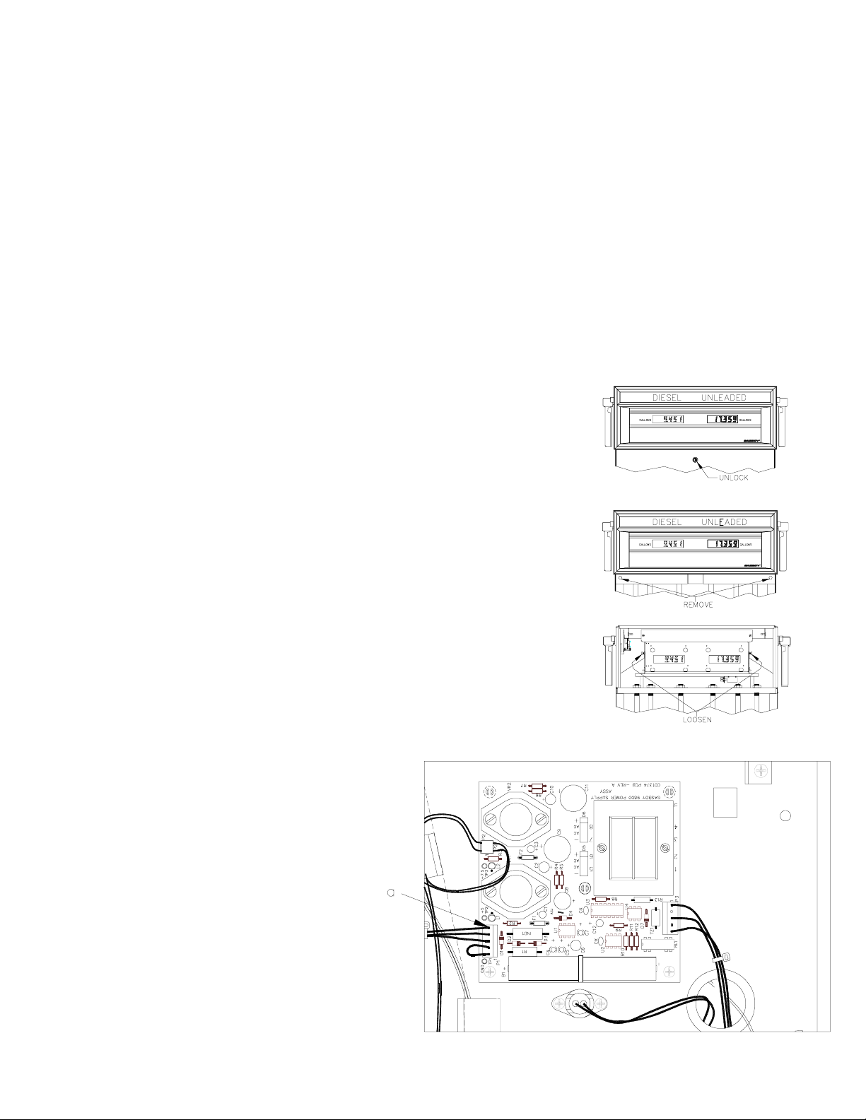
3. Unlock and remove the front panel.
4. Remove the two bolts located over the tabs of the bezel assembly. Lift the bezel
assembly upwards and out to remove.
QTY PART NO. DESCRIPTION
2 C35415 Cover, Lamp Screen or
2 C35949 Cover, Lamp Screen
4 C04037 Screw, 8-32 x 3/8
4 C01171 Washer, #8 Spring Lock
4 067126 Washer, #8
13 0M0042 Nylon Tie Wrap
7 C09694 Wire Twist Standoff
2 C02207 Cable Clamp
Pump/Dispenser Installation Manual
5. Loosen, and remove if necessary, two screws located on the left and right door
support brackets and pivot the display panel down.
6. Repeat Steps 3 through 5 on the other side
of the pump.
7. Pull the connector off P1 (a) on the power
supply. After a few seconds, reconnect
P1.
C35404 Rev. 8120 Page 1

8. From the CPU PCB, pull off the AC, pulser, and handle
cables (a). From the RS-485 PCB or Pump I/F PCB, pull
off the DC cable (b). Disconnect the red, blue, orange,
and black wires from screws 1 and 2 of the pump relays
(c). Push all of the cables down through the platform
bushings.
9. On one of the display panels, pull off the ribbon cables (a) from the LCD Display PCBs and the power cables (b) from
the LED Backlight PCBs. Remove one end of the ground braid cable (c) from the display panel. Remove the two
screws (d) from one of the support brackets. Be careful not to let the display panel fall while removing the support
bracket. Slide the panel away from the remaining support bracket and pull it out of the cabinet.
10. Disconnect the MICRO connector from the power bracket.
11. Remove the four nuts, washers, and lockwashers securing the platform assembly to the chassis. While standing on the
side with the display panel still installed, lift the platform up and out toward you.
Page 2 C35404 Rev. 8120
 Loading...