

Page 1

Introduction
This manual provides installation instructions for the Gasboy Automatic Temperature
Compensation (ATC) Kits:
Contents
Section Page ...
Introduction 1
Important Safety Information 6
Installation 8
Appendix: Totalizer Display Information 25
MDE-4351A
Gasboy ATC Kits 039086 and 039087
Installation Manual
February 2006
• 039086 for Twin 9800 Unit
• 039087 for Single 9800 Unit
Required Reading 1
Required Tools 1
Abbreviations and Acronyms 2
Parts Lists 3
Installing the 039086 ATC Kit in Single Unit 8
Installing the 039087 ATC Kit in T win Unit 16
Required Reading
Before installing a kit, the installer m ust read, understand, and follow:
• This manual
• NFPA 30A, The Automotive and Marine Service Station Code
• NFPA 70, The National Electric Code
• Applicable federal, state and local codes and regulations
Failure to do so may adversely affect the safe use and operation of the equipment.
Note: This kit must be installed by a Gasboy Authorized Service Contractor (ASC) to ensure
warranty.
Required Tools
The following tools are needed to install the ATC Kits:
• Open end wrench set
• Flat-tip s crewdriver
• Cross-tip screwdriver
•Allen
MDE-4351A Gasboy ATC K its 039086 and 039087 Installation Manual • February 2006 Page 1
®
wrench set
Page 2

Introduction
Abbreviations and Acronyms
The following are abbreviations and acronyms used in this document.
Abbreviation
or Acronym Expansion
ATC Automatic Temperature Compensation
ASC Authorized Service Contractor
AWG American Wire Gauge
CFR Code of Federal Regulations
CPU Central Processing Unit
DIP Dual Inline Package
ESD Electrostatic Discharge
I.D. Inside Diameter
IS Intrinsic Safety
LCD Liquid Crystal Display
LPM Liters Per Minute
NEC National Electrical Code
NFPA National Fire Protection Association (http://www.nfpa.org/Home/index.asp)
NPT National Pipe Thread
OSHA Occupational Safety & Health Administration (http://www.osha.gov/)
PCB Printed Circuit Board
STP Submerged Turbine Pump
®
TPS Teflon
Pipe Sealant
Page 2 MDE-4351A Gasboy ATC Kits 039086 and 039087 Installation Manual • February 2006
Page 3

Introduction
Parts Lists
039086 - ATC Kit for Twin Unit
Kraus Part Number Description Quantity
®
SK449C PCB Assembly in LP-70 Polycase
SK460 ATC Display Adapter Board (460A4 in Figure 1)1
SK461 Pulser/Handle Adapter Board (461A2 in Figure 1)1
218AY00 Dual Intrinsic Safety Barrier 1
- 5/16-inch Flat Washer (part of 218AY00) 2
- 5/16-inch Hex Nut (part of 218AY00) 1
212AY05 Dual Probe Connector Assembly 1
W172 3-Wire Harness for Intrinsic Safety Barrier 1
W199 Probe Assembly 2
BC407 Thermowell 2
235-C Thermowell plug 2
122-B 1/8-inch NPT X 1-inch Coupling 2
BC546 120-B 1/8-inch NPT Adapters Drilled to 17/64-inch I.D. 2
103-B 1/8-inch NPT Couplings 2
W283 Display Adapter Harness 1
W284 Pulser/Handle Ribbon Cable 2
- 18-22 AWG Crimp Splices 10
DC256W White “Volume Corrected to 15° C” Label 4
BC1380 Serialized AV-2322 Nameplate 1
Box and BC1379 Mounting Sponge 1
039087 - ATC Kit for Single Unit
Kraus Part Number Descri ption Quantity
SK449C PCB Assembly in LP-70 Polycase Box and BC1379 Mounting Sponge 1
SK460 ATC Display Adapter Board (460A4 in Figure 1)1
SK461 Pulser/Handle Adapter Board (461A2 in Figure 1)1
218AY00 Dual Intrinsic Safety Barrier 1
- 5/16-inch Flat Washer (part of 218AY00) 2
- 5/16-inch Hex Nut (part of 218AY00) 1
212AY04 Single Probe Connector Assembly 1
W171 2-Wire Harness for Intrinsic Safety Barrier 1
W199 Probe Assembly 1
BC407 Thermowell 1
235-C Thermowell plug 1
122-B 1/8-inch NPT Coupling 1
BC546 120-B 1/8-inch NPT Adapters Drilled to 17/64-inch I.D. 1
103-B 1/8-inch NPT Couplings 1
W283 Display Adapter Harness 1
W284 Pulser/Handle Ribbon Cable 1
- 18-22 AWG Crimp Splices 10
DC256W White “Volume Corrected to 15° C” Label 2
BC1380 Serialized AV-2322 Nameplate 1
MDE-4351A Gasboy ATC K its 039086 and 039087 Installation Manual • February 2006 Page 3
Page 4
Introduction
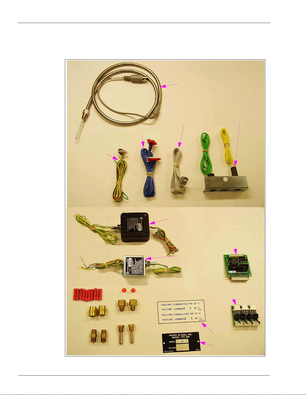
Parts Identification
Figure 1 and Figure 2 provide an identification of the parts in the 039086 and 039087 kits.
Figure 1: The 039086 and 039087 Kits Parts Identification
W199 Probe Assembly
212AY04 Single Probe/
W284 Pulser/
Handle Ribbon
Cable
W283 Display
Adapter Harness
W172 3-Wire Harness
(For Twin Unit)
~ OR ~
W171-2 Wire Harness
(For Single Unit)
212AY05 Dual Probe
Connector Assembly
Crimp Splices
103B Couplings
122-B Nipples
235C Thermowell Plugs
BC546 120-B Adapters
BC407 Thermowells
218AY00 Dual Intrinsic Safety
Barrier (Newer Version)
460A4 Display
Adapter Board
218A Y00 Dual Intrinsic
Safety Barrier (Older
Version)
461A2 Pulser/Handle
Adapter Board
BC256W Label
BC1380 Nameplate
Note: If your kit is for a single unit, you will have only one of some of these items.
Page 4 MDE-4351A Gasboy ATC Kits 039086 and 039087 Installation Manual • February 2006
Page 5
Introduction
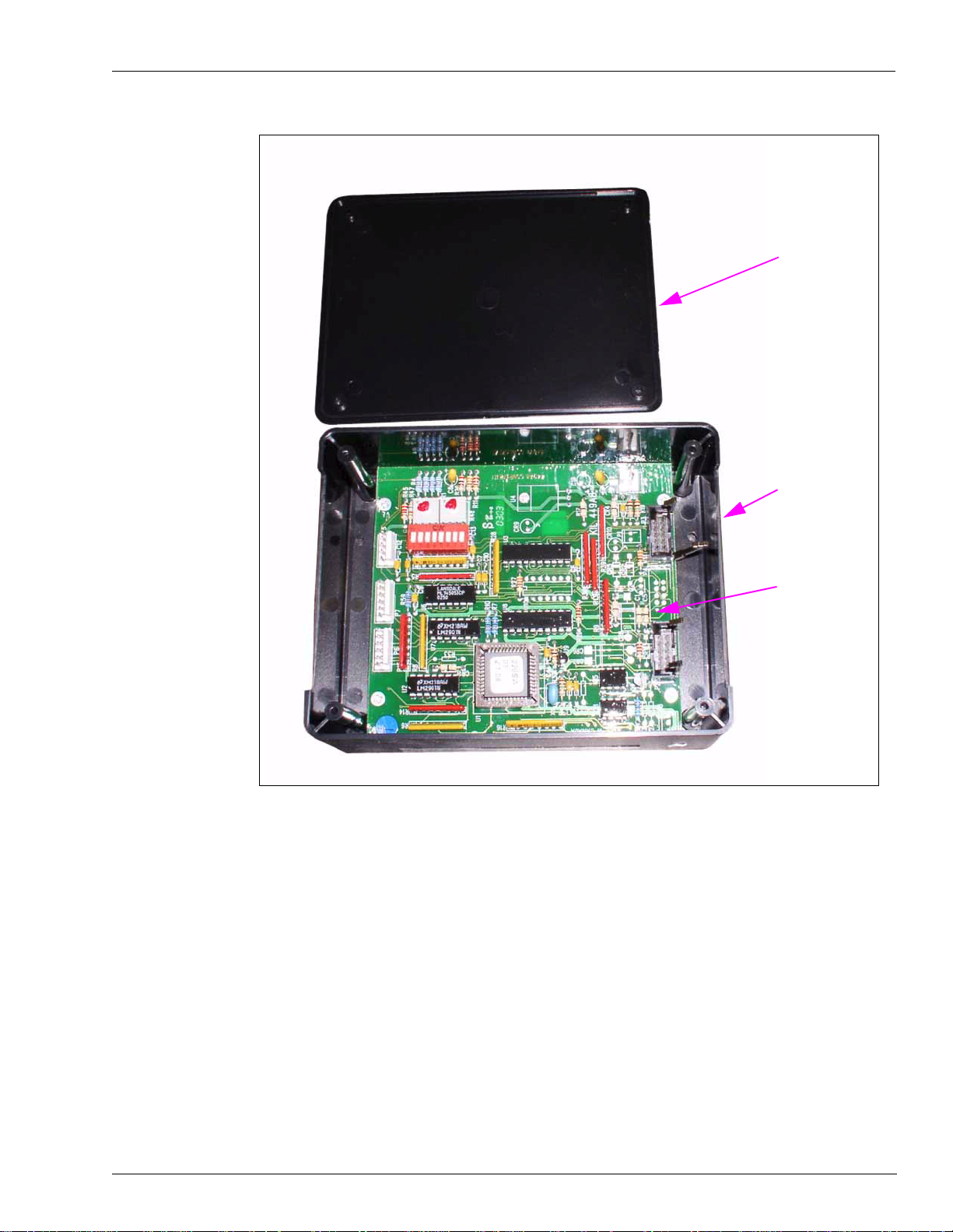
Figure 2: SK449C LP-70 Polycase Box and Cover (Part of 039086 and 039087 Kits)
Cover
LP-70 Polycase
Box
SK449C PCB
Assembly
MDE-4351A Gasboy ATC K its 039086 and 039087 Installation Manual • February 2006 Page 5
Page 6
Important Safety Information
The EMERGENCY STOP, ALL STOP, and
PUMP STOP buttons at the cashier’s station
WILL NOT shut off electrical power to the
pump/dispenser.
This means that even if you activate these
stops, fuel may continue to flow uncontrolled.
You must use the TOTAL ELECTRICAL SHUTOFF in the case of an emergency and not only
these cashier station “stops.”
!
WARNING
!
Important Safety Information
This section introduces the hazards and safety precautions
associated with inst alling , inspecting, main tainin g or servicing
this product. Before performin g any t ask on this pro duct, read
this safety information and the applicable sections in this
manual, where additional hazards and safety precautions for
your task will be found. Fire, explosion, electrical shock or
pressure release could occur and cause death or serious
injury if these safe service procedures are not followed.
Preliminary Precautions
You are working in a potentially dangerous environment of
flammable fuels, vapors, and high voltage or pressures. Only
trained or authorized indiv iduals know ledgeable in the related
procedures should install, inspect, maintain or service this
equipment.
Read the Manual
Read, understand and follow this manual and any other
labels or related mate rials suppli ed with this eq uipment. If y ou
do not understand a procedure, call a Gasboy Authorized
Service Contractor or call the Ga sb oy Serv ic e Center at 1800-444-5529. It is imp erative to y our safety and the sa fety of
others to understand the procedures before beginning work.
Follow the Regulations
There is applicable information in NFPA 30A; Automotive and
Marine Service Code, NFPA 70; National Electrical Code (NEC),
OSHA regulations and federal, state, and local codes which
must be followed. Failure to install, inspect, maintain or
service this equipment in accordance with these codes,
regulations and standards may lead to legal citations with
penalties or affect the safe use and operation of the
equipment.
Emergency Total Electrical Shut-Off
The first and most impo rtant information you mus t know is
how to stop all fuel flow to the pump and island. Locate the
switch or circuit breakers that shut-off all power to all fueling
equipment, dispensing devices, and submerged turbine
pumps (STPs).
Total Electrical Shut-Off Before Access
Any procedure requiring access to electrical components or
the electronics of the dispenser requires total electrical shutoff of that unit. Know the function and location of this switch
or circuit breaker before in sp ect ing , installing, maintaining, or
servicing Gasboy equipment.
Evacuation, Barricading and Shut-Off
Any procedures requiring accessing the pump/dispenser or
STPs requires the following three actions:
- An evacua tion of all unauthorized persons and vehicles
using safety tape, cones or barricades to the effected units
- A total electrical shut-off of that unit
Replacement Parts
Use only genuine Gasboy replacement parts and retrofit kits
on your pump/dispenser. Using parts other than genuine
Gasboy replacement parts could create a safety hazard and
violate loc al regulations.
Safety Symbols and Warning Words
This section provides important informati on about warning
symbols and boxes.
Alert Symbol
This safety alert symbol is used in this manual and on
warning labels to alert you to a precaution whi c h m ust be
followed to prevent potential personal safety hazards. Obey
safety directives that follow this symbol to avoid possible
injury or death.
Signal Words
These signal words used in this manual and on warning labels
tell you the seriousness of particular safety hazards. The
precautions that follow must be followed t o pre vent death,
injury or damage to the equipment
DANGER - This signal word is used to alert you to a
hazard to unsafe practice which will resul t in deat h or
serious injury
WARNING - This alerts you to a hazard or unsafe
practice that could result in death or serious injury.
CAUTION with Alert symbol - This signal word
designates a hazard or unsafe practice which may
result in minor injur y.
CAUTION without Alert symbol - When used by itself,
CAUTION designates a hazard or unsafe practice
which may result in property or equipment damage.
Working With Fuels and Electrical Energy
Prevent Explosions and Fires
Fuels and their vapors will become explosive if ignited. Spilled
or leaking fuels cause vapors. Even filling custom er tanks will
cause explosive vapors in the vicinity of dispe nser or island.
Page 6 MDE-4351A Gasboy ATC Kits 039086 and 039087 Installation Manual • February 2006
Page 7
Important Safety Information
No Open Flames
Open flames from matches, lighters, welding torches
or other sources can ignite fuels and their vapors.
No Sparks - No Smoking
Sparks from starting vehicles, starting or using power tools,
burning cigarettes, cigars or pipes can also ignite fuels and
their vapors. Static electricity, including an electrostatic
charge on your body, can cause a spark sufficient to ignite
fuels and thei r vapo rs. Aft er gett ing ou t of a veh icle, touch the
metal of your vehicle to discharge any electrostatic charge
before you approach the dispenser island.
Working Alone
It is highly recommended that someone who is capable of
rendering first aid be present during servicing. Be familiar
with Cardiopulmonary Resuscitation (CPR) methods if you
are working with or around high voltages. This information is
available from the American Red Cross. Always advise the
station personnel about where you will be working, and
caution them not to activate power while you are working on
the equipment. Use the OSHA tag out and lock out
procedures. If you are not fam iliar wit h this require ment, ref er
to information in the service manual and OSHA
documentation.
Working With Electricity Safely
Be sure to use sa fe an d established pra ct ice s in w ork in g with
electrical devices. Poorly wired devices may cause a fire,
explosion or electrica l sh ock . Be su re grou nding connections
are properly made. Make sure that sealing devices and
compounds are in place. Be sure not to pinch wires when
replacing covers. Follow OSHA Lock-Out and Tag-Out
requirements. Station employees and service contractors
need to underst and and comply wit h th is pro gra m c om pl ete ly
to ensure safety while the equipment is down.
Emergency First Aid
Informing Emergency Personnel
Compile the following information for emergency personnel:
Location of accident (for example, address, front/back of
building, and so on.)
Nature of accident (for example, possible heart attack, run
over by car, burns, and so on.)
Age of victim (for example, baby, teenager, middle-age,
elderly.)
Whether or not victim has received first aid (for example,
stopped bleeding by pressu re, and so on.)
Whether or not a victim has vomited (for example, if
swallowed or inhaled something, and so on.)
WARNING
!
Gasoline ingeste d may c ause unc onsciou sness
and burns to internal organs.
Do not induce vomiting.
Keep airway open.
Oxygen may be needed at scene.
Seek medical advice immediately.
WARNING
!
Gasoline inhaled may cause unconsciou sness
and burns to lips, mouth and lungs.
Keep airway open.
Seek medical advice immediately.
WARNING
!
Gasoline spilled in ey es may cause bur ns to eye
tissue.
Irrigate eyes with water for approximately 15
minutes.
Seek medical advice immediately
Hazardous Materials
Some materials present inside electronic enclosures may
present a health hazard if not handled correctly. Be sure to
clean hands after handling equipment. Do not place any
equipment in mouth.
!
WARNING
This area contains a chemical known to the State of
California to cause cancer.
WARNING
!
Gasoline spilled on skin may cause burns.
Wash area thoroughly with clear/water.
Seek medical advice immediately.
IMPORTANT: Oxygen may be needed at scene if gasoline
has been ingested or inhaled. Seek medical advice
immediately.
Lockout/Tagout
WARNING
!
This area contains a chemical known to the State of
California to cause birth defects or other reproductive
harm.
Lockout/Tagout covers servicing and maintenance of
machines and equipment in which the unexpected
energization or start up of the machine(s) or equipment or
release of stored energy could cause injury to employees or
personnel. Lockout/Tagout applies to all mechanical,
hydraulic, chemical or other energy, but does not cover
electrical hazards. Referenc e Sub part S of 2 9 CFR Pa rt 1910
IMPORT ANT: Oxygen may be needed at scene if gasoline
has been ingested or inhaled. Seek medical advice
immediately.
- Electrical Hazards, 29 CFR Part 1910.333 contains specific
Lockout/Tagout provision for electrical hazards.
MDE-4351A Gasboy ATC K its 039086 and 039087 Installation Manual • February 2006 Page 7
Page 8
Installation
Installation
Preparation
1 Request permission from the manager/owner to remove power from the unit and then remove
2 Make sure you have the proper kit for the model dispenser to be retrofitted.
3 Using the proper key for the unit, unlock and remove the doors from both sides of the unit.
4 Using a cross-tip screwdriver, at side 1 of the unit, loosen the two screws (one on each side of
Use electrostatic discharge (ESD) precautions to place yourself at a neutral
static-free potential by touching an unpainted metal surface and by using a wrist
strap connected to a grounded metal frame or chassis.
power using normal procedures. Observe the lockout/tagout safety procedures.
Place doors in a safe place to prevent damage or scratches.
the display cove r), s pring the s crew ho lders and scre ws out from t he dis pl ay cove r and pull the
display cover forward. The cover will pivot down in a horizontal position allowing access to
the electronics section of the unit.
Installing the 039086 ATC Kit in Single Unit
1 In the kit, locate the LP-70 Poly case box wit h SK449C PCB mounted insid e. Remove the four
mounting screws securing the cover and remove the cover from the box. Save screws and
cover for reinstalling later.
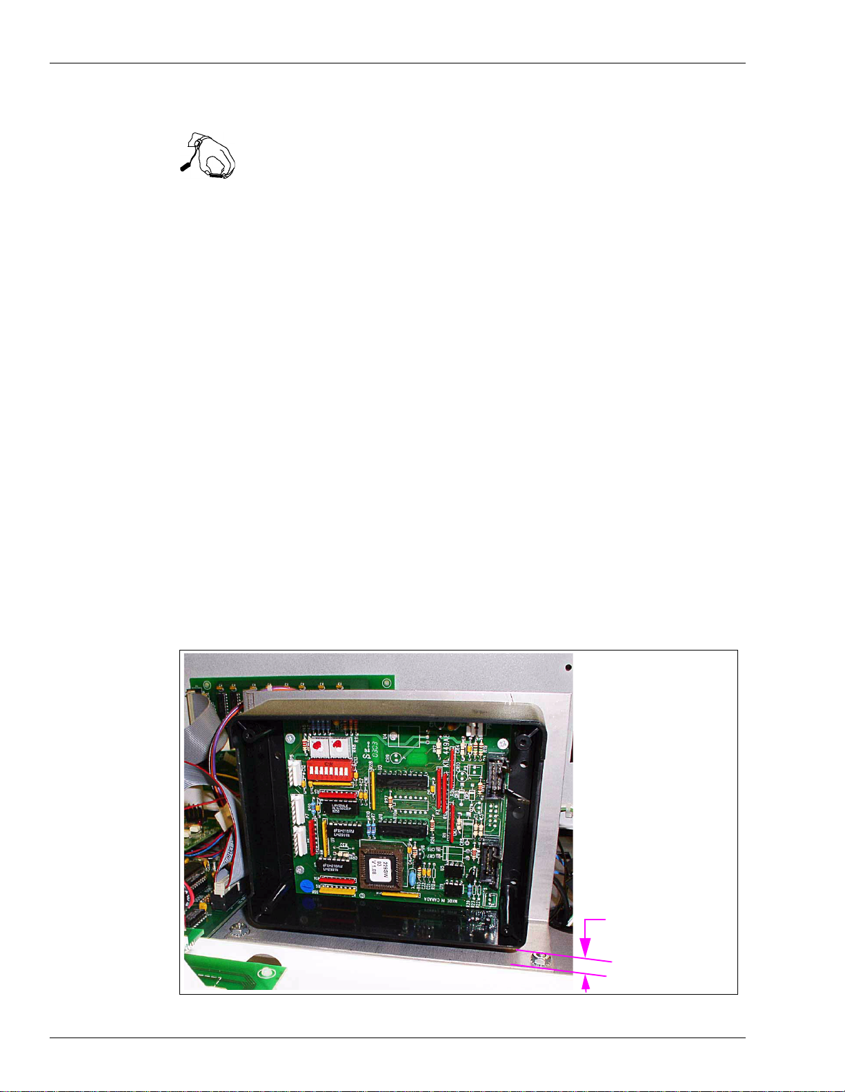
2 Peel the protective cover from the mounting sponge (on the back of the polycase box) and
mount the box as shown in Figure 3. Mount approximately 1/2-inch up from shelf (1/2-inch
clearance underneath shelf).
Figure 3: Mounting the LP-70 Polycase Box
Approximately 1/2-inch
Clearance
Page 8 MDE-4351A Gasboy ATC Kits 039086 and 039087 Installation Manual • February 2006
Page 9

Installation
3 In the kit, locate the 218AY00 single intrinsic safety (IS) barrier and 212AY04 single probe
connector assembly. Remove the nut and washer from the mounti ng stud on the IS barrier a nd
slide them off the wires. Save for reuse.
4 Feed the wires extending from the IS barrier mounting stud through the hole in the shelf as
shown in Figure 4 and place the mounting stud through the hole.
Figure 4: Mounting the IS Barrier on the Shelf
Notch in Shelf
IS Barrier
Probe Connector
Assembly
5
Place the wires extending from the mounting stud through the mounting hole in the single
probe connector assembly and place the connector assembly up on the stud (underneath the
shelf).
CAUTION
If your kit contains the newer version of the 218Y00 IS Barrier (see Figure 1 for
identification) and your unit does NOT have the notch in the shelf (Figure 4), the IS
barrier will not mount. DO NOT try to mount the IS barrier if the shelf does not have
the notch.
6 Place the washer and nut over the wires and turn nut onto the stud securing the IS barrier and
probe connector. Tighten snugly but do not overtighten.
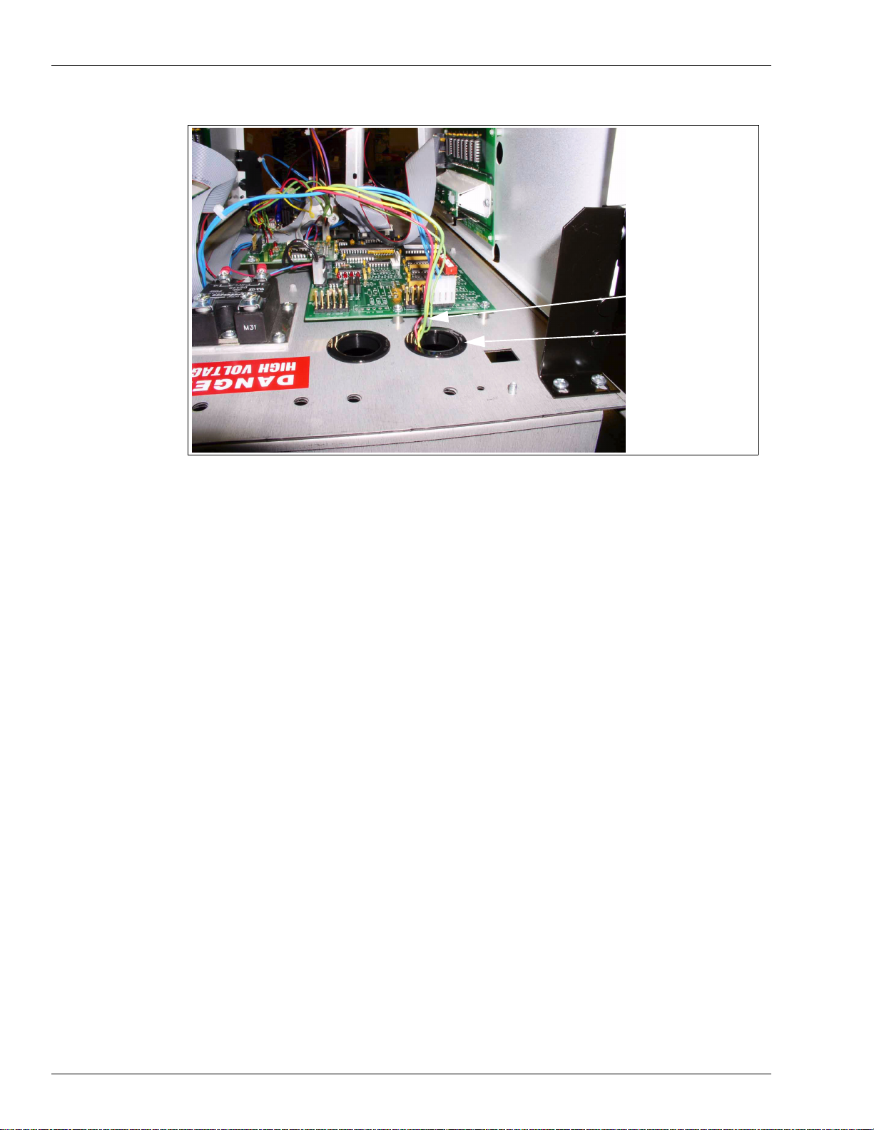
7 Place the wires extending from the top of the IS barrier up through the grommet in the upper
shelf as sho wn in Figure 5.
Note: Figure 5 shows tw o pair s of wires (for a twin unit inst allat io n). The re is only one pai r of
wires in this single unit instal lation.
MDE-4351A Gasboy ATC K its 039086 and 039087 Installation Manual • February 2006 Page 9
Page 10

Installation
Figure 5: Wires from IS Barrier Extending Through Shelf
Wires from IS Barrier
Grommet
8
At the C06391 9800 CPU P rinted Ci rcuit Board Assembl y (Fig ure 6 and Figure 7), disc onnect
the connectors connected to the Pulser 1 and Handles jacks.
9 In the kit, locate the 461A2 Circuit Board Assembly (see Figure 1 for identity). Connect the
assembly to the jacks labeled Pulser 1, Handles, and Pulser 2 on the 9800 CPU PCB.
10 Reconnect the connector removed in Step 8 to the 461A2 Circuit Board Assembly (directly
above the Pulser 1 and Handles connectors).
11 At the 9800 CPU PCB Assembly (Fi gure 6 and Figure 7), disconnect the connector connected
to the LCD Display jack.
12 In the kit, locate the 460A4 Circuit Board Assembly (see Figure 1 for identity). Connect the
assembly to the jack labeled LCD Display on the 9800 CPU PCB.
13 Reconnect the connect or remov ed in S tep 1 1 t o th e 460A4 Cir cuit Boa rd Assembly jack J 1 (in
center of board).
Page 10 MDE-4351A Gasboy ATC Kits 039086 and 039087 Installation Manual • February 2006
Page 11
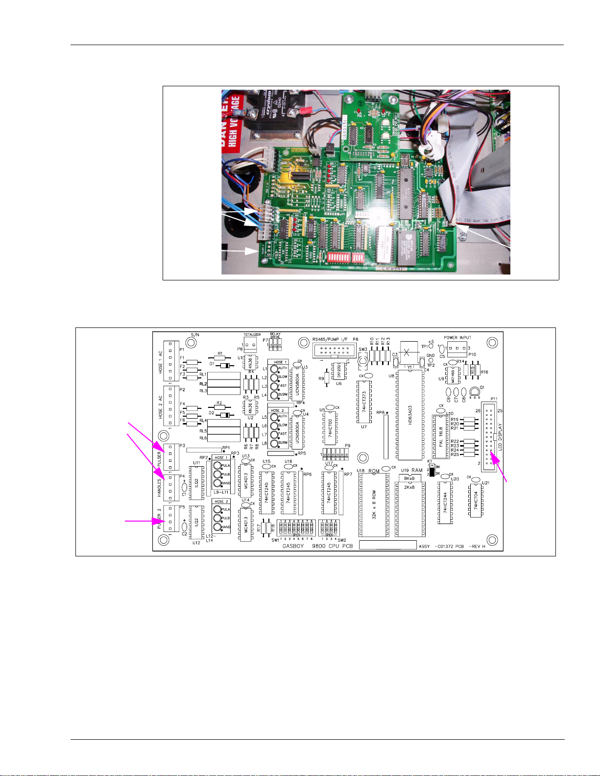
Figure 6: C06391 9800 CPU Printed Circuit Board (Photograph)
Pulser 1 and
Handles Jac ks
Installation
Pulser 1 and
Handles Ja cks
Pulser 2 J ack
Pulser 2 Jack
Figure 7: C06391 9800 CPU Printed Circuit Board (Drawing)
LCD
Display
Jack
LCD
Display
Jack
14
In the kit, locate the W284 Pulser/Handle Ribbon Cable (see Figure 1 for identity).
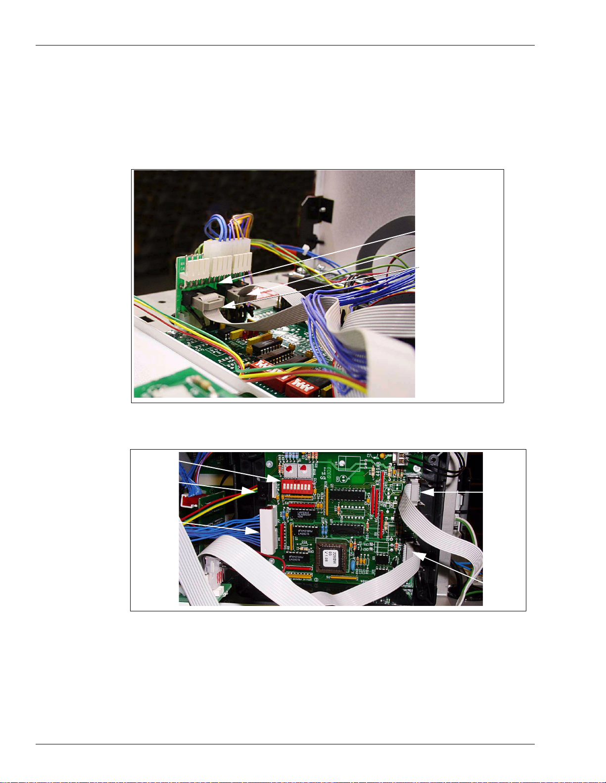
15 Connect one end of the W284 cable to P1 on the 461A2 board (Figure 8) and the other end to
P2 in the LP-70 Polycase box (Figure 9).
16 Connect one end of the second W284 cable to P8 o n t he 4 61A2 b oard (Figure 8) and the other
end to P3 in th e LP-70 Polyc ase box (Figure 9).
Note: Be sure the cables are connected to the connectors as follows:
P1 of 461A2 to P2 of LP-70 Polycase box
P8 of 461A2 to P3 of LP-70 Polycase box
MDE-4351A Gasboy ATC Kits 039086 and 039087 Installation Manual • February 2006 Page 11
Page 12

Installation
Figure 8: 461A2 Circuit Board in Place with Connections Made
461A2 PCB
P1
P8
Figure 9: LP-70 Polycase Box Showing Connections
DIP
Switches
P5
P6/P7
17
In the kit, locate the W283 Display Adapter Harness (see Figure 1 for identification).
P3
P2
18 Connect one connector on the harness (both are the same) to J4 on the 460A4 Circuit Board
Assembly (Figure 10) and the other connector to P6/P7 in the LP-70 Polycase box (Figure 9).
Page 12 MDE-4351A Gasboy ATC Kits 039086 and 039087 Installation Manual • February 2006
Page 13

Figure 10: 460A4 Circuit Board in Place with Connections Made
J4
460A4 Circuit
Board Assembly
W283 Display Adapter
Connector on J4
Installation
19
In the kit, loc ate the W171 2-wire harness for IS Barrier.
20 Place the connector on the harness on P5 of the LP-70 Polycase box (Figure 9).
21 Using two of the crimp splices, connect the wires of the harness to the wires extending from
the top of th e IS barrier. Match co lor codes.
22 Using an OM0205 cap or an appropriate size wire nut (OM0205 cap or wire nut is not part or
the kit), cap the end of the green wire from the IS barrier.
23 Connect the ground wire (wire with eyelet connector) to the nearest true ground.
24 Disconnect cable going to P6 connector of the Pump CPU board.
25 Connect the cable that was disconnected in previous step to P9 connector in the LP-70
Polycase box.
26 If the user wants to be able to display electronic totals, a second cable (C06003) must be
installed and connected to the P6 connector on the Pump CPU board.
27 In the LP-70 Polyca se box, locate the DIP switches shown in Figure 9 and set the switches for
the proper unit as shown in the following table:
DIP Switch Settings
Switch
Number Switch Function Settings
1 Product 1 ON for Diesel, OFF for Gasoline
2 Product 2 ON for Diesel, OFF for Gasoline
3Not used
MDE-4351A Gasboy ATC Kits 039086 and 039087 Installation Manual • February 2006 Page 13
Page 14

Installation
DIP Switch Settings
Switch
Number Switch Function Settings
4Not used
5 Pulser Multiplier ON for 9850, OFF for 9852/9853
6 Number of Probes ON for two (2) probes, OFF for one (1) probe
7 Pulser Adder ON for 9840
8 ATC ON for ATC ON, OFF for ATC OFF
28 Remount the LP-70 Polycase box cover removed in step 1.
29 Using two of the crimp spl ices, conne ct the two ye llow wires extending from the bot tom of the
IS barrier mounti ng st ud to t he two blue wi res a ttac hed to the singl e pro be conn ector as sembly.
30 Using two OM0205 caps or suitable-size wire nuts (OM0205 caps or wire nuts are not part of
the kit.), cap the end of the two green wires extending from the bottom of the IS barrier.
31 In the kit, locate the foll owing: (See Figure 1 for parts identity)
• W199 probe assembly
• BC407 Thermowell
• 235-C Thermowell Plug
• BC546 Adapter
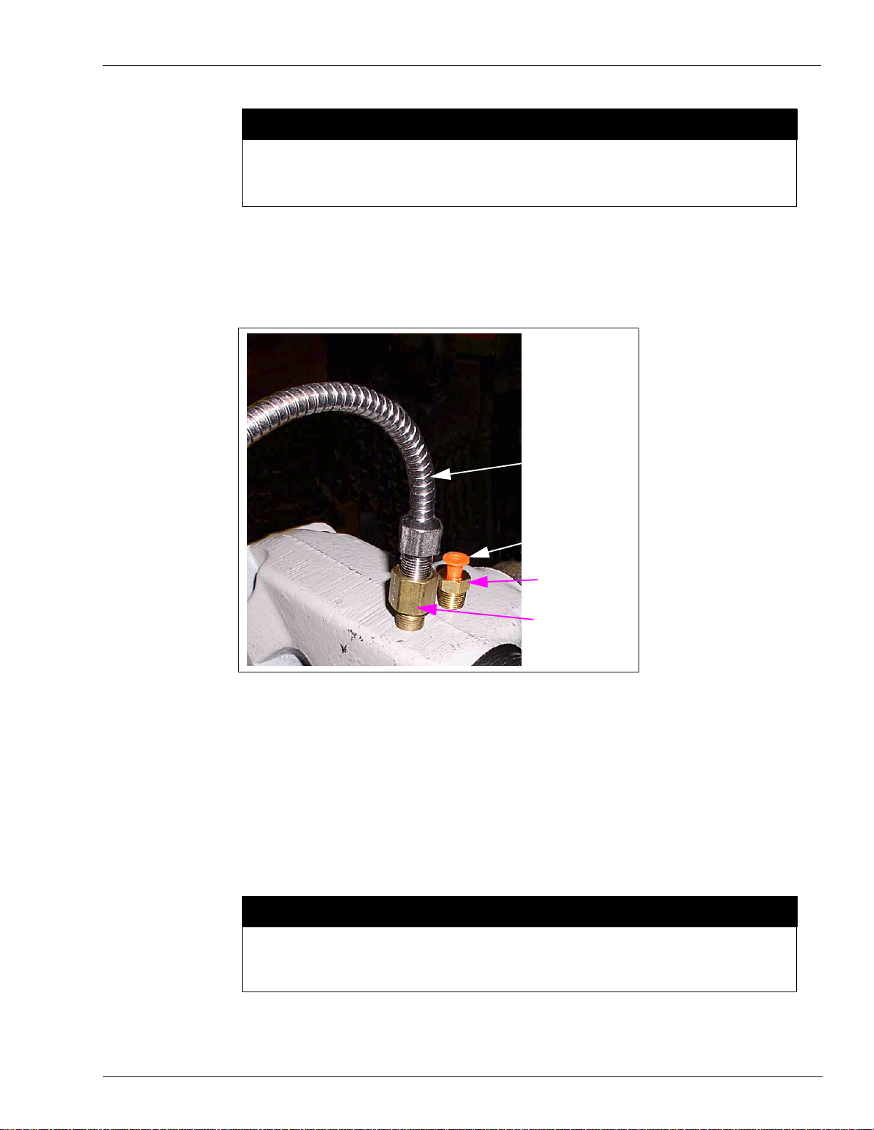
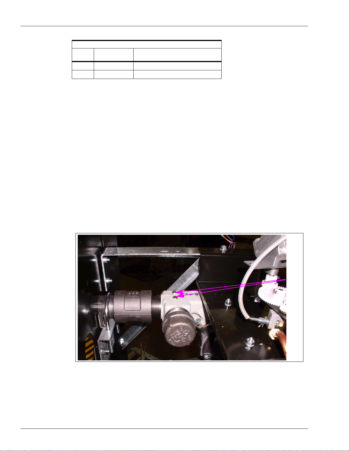
32 Underneath the shelf (where the IS barrier is mounted), locate the two plugs in the hydraulic
coupling (Figure 11).
Figure 11: Probe Assembly Mounting Location
Plugs
Using the appropriate size Allen wrench, remove the two plugs.
33
Page 14 MDE-4351A Gasboy ATC Kits 039086 and 039087 Installation Manual • February 2006
Page 15
CAUTION
Installation
When applying
hole first free of sealant to prevent the sealant from entering, and possibly damaging or
inhibiting proper operation of, the unit.
34 Using SAF-T-LOK TPS sealant, coat the BC407 Thermowell threads and thread into one of
SAF-T-LOK® TPS sealant on threads, leave the two threads that enter the
the holes where the plugs were removed in the previous step (Figure 12).
Figure 12: Thermowell and Probe Assembly Connections
Probe Assembly
Thermowell Plug
Thermowell
Adapter
35
Using a proper size wrenc h, tig hten th e ther mowell and pl ace the 235-C Ther mowell p lug int o
the thermow ell.
36 Coat the threads of the BC546 Adapte r with SAF-T-LOK TPS sealant and turn it into th e other
hole where the plugs were removed in step 33 (see Figure 12).
37 Coat the threads of the W199 Probe Assembly with SAF-T-LOK TPS sealant and turn it into
the BC546 a dapter mounted in the previous step.
38 Using the proper size wrench, tighten both the adapter and probe.
CAUTION
Be sure the threads on the thermowell, adapter, and probe assembly are properly
coated with the SAF-T-LOK TPS sealant and tightened properly to prevent leaks
.
MDE-4351A Gasboy ATC Kits 039086 and 039087 Installation Manual • February 2006 Page 15
Page 16
Installation
39 Connect the other end of th e probe to Probe Connector Asse mbly in the conne ctor labe led “1”.
(See Figure 4 for Probe Connector Assembly location.)
40 Go to “Completing Installation” on page 24 in this manual.
Installing the 039087 ATC Kit in Twin Unit
1 In the kit, locate the LP-70 Poly case box wit h SK449C PCB mounted insid e. Remove the four
mounting screws securing the cover and remove the cover from the box. Save screws and
cover for reinstalling later.
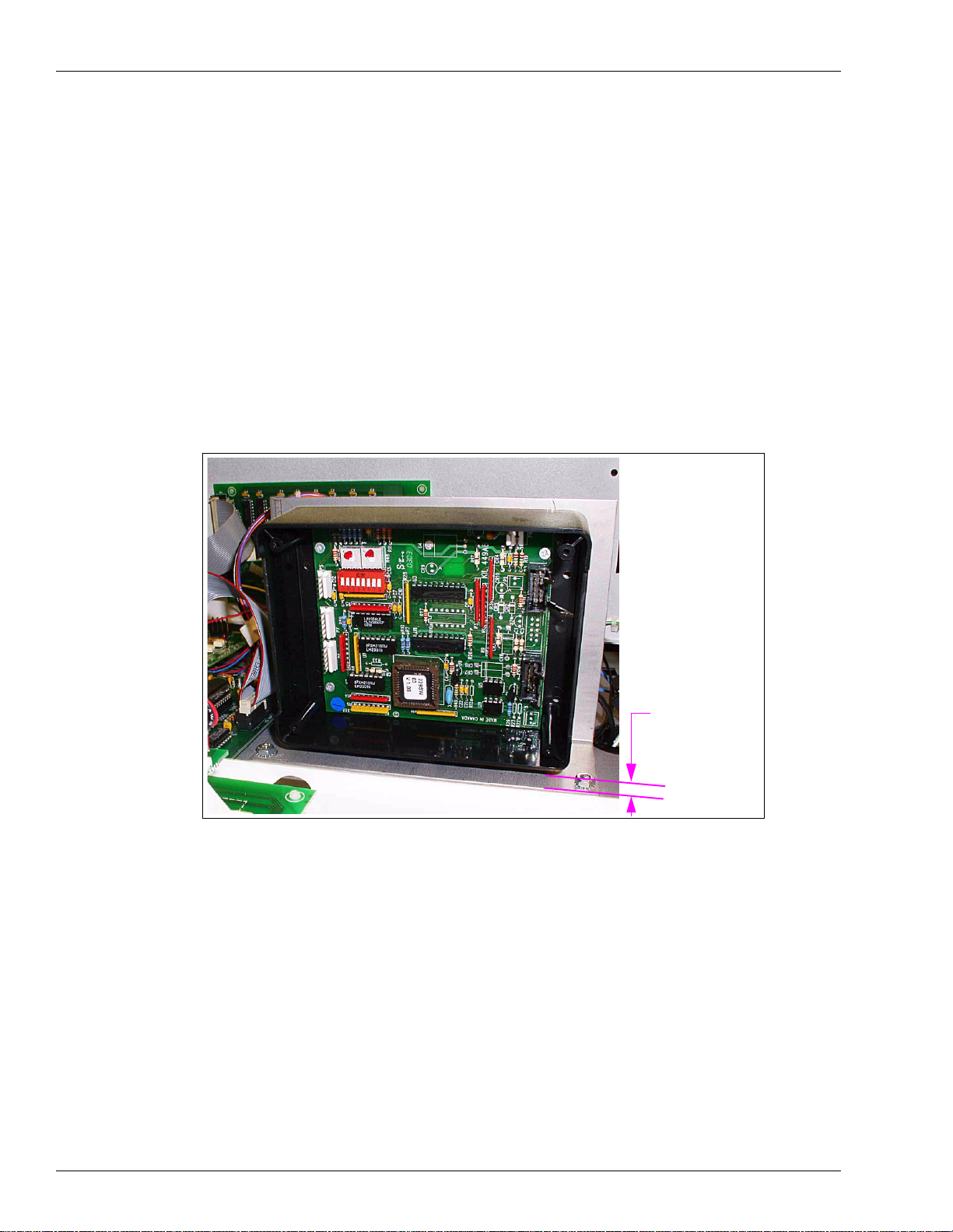
2 Peel the protective cover from the mounting sponge (on the back of the polycase box) and
mount the box as shown in Figure 13. Mount approximately 1/2-inch up from shelf.
Figure 13: Mounting the LP-70 Polycase Box
Approximately
1/2-inch
Clearance
3
In the kit, locate the 218AY00 single IS barrier and 212AY05 dual probe connector assembly.
Remove the nut and washer from the mounting stud on the IS barrier and slide them off the
wires. Save for reuse.
4 Feed the wires extending from the IS barrier mounting stud through the hole in the shelf as
shown in Figure 14 and place the mounting stud through the hole.
Page 16 MDE-4351A Gasboy ATC Kits 039086 and 039087 Installation Manual • February 2006
Page 17
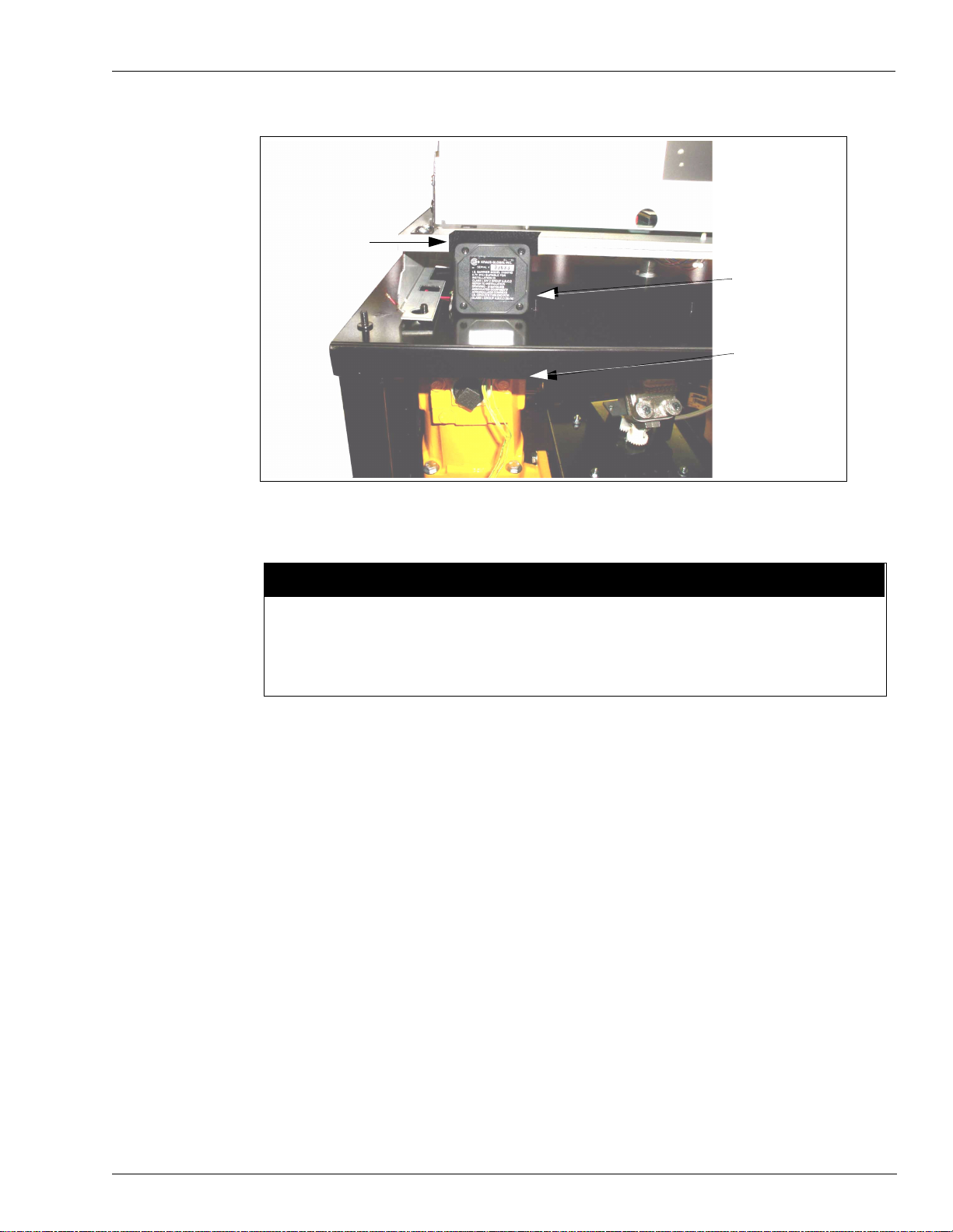
Figure 14: Mounting the IS Barrier on the Shelf
Notch in Shelf
Installation
IS Barrier
Probe Connector
Assembly
5
Place the wires exte nding fr om the moun ting s tud th rough t he mounting hole i n the dual p robe
connector assembly and place the connector assembly up on the stud (underneath the shelf).
CAUTION
If your kit contains the newer version of the 218Y00 IS Barrier (see Figure 1 for
identification) and your unit does NOT have the notch in the shelf (Figure 14), the IS
barrier will not mount. DO NO T try to mount the IS barrier if the shelf does not have the
notch.
6 Place the washer and nut over the wires and turn nut onto the stud securing the IS barrier and
probe connector. Tighten snugly but do not overtighten.
7 Place the wires extending from the top of the IS barrier up through the grommet in the upper
shelf as sho wn in Figure 15.
MDE-4351A Gasboy ATC Kits 039086 and 039087 Installation Manual • February 2006 Page 17
Page 18
Installation
Figure 15: Wires from IS Barrier Extending Through Shelf
Wires from IS Barrier
Grommet
8
At the C06392 9800 CPU Printed Circuit Board Assembly (Figure 16 and Figure 17),
disconnect the connector connected to the Pulser 1, Handles, and Pulser 2 jacks.
9 In the kit, locate the 461A2 Circuit Board Assembly (see Figure 1 for identity). Connect the
assembly to the jacks labeled Pulser 1, Handles, and Pulser 2 on the 9800 CPU PCB.
10 Reconnect the connector removed in Step 8 to the 461A2 Circuit Board Assembly (directly
above the Pulser 1, Handles and Pulser 2 connectors).
11 At the 9800 CPU PCB Assembly (Figure 16 and Figure 17), disconnect the connector
connected to the LCD Display jack.
Page 18 MDE-4351A Gasboy ATC Kits 039086 and 039087 Installation Manual • February 2006
Page 19

Installation
12 In the kit, locate the 460A4 Circuit Board Assembly (see Figure 1 for identity). Connect the
assembly to the jack labeled LCD Display on the 9800 CPU PCB.
13 Reconnect the connector remov ed in S tep 1 1 t o the 460 A4 Cir cuit Boa rd Assembly j ack J1 (i n
center of board).
Figure 16: C06392 9800 CPU Printed Circuit Board (Photograph)
Pulser 1 and
Handles Jacks
Pulser 1 and
Handles Ja cks
Pulser 2 J ack
Pulser 2 Jack
Figure 17: C06392 9800 CPU Printed Circuit Board (Drawing)
LCD
Display
Jack
LCD
Display
Jack
14
In the kit, locate the two W284 Pulser/Handle Ribbon Cables (see Figure 1 for identity).
15 Connect one end of one W284 cable to P 1 on the 461A2 b oard (Figure 18) and the other end to
P2 in the LP-70 Polycase box (Figure 19).
MDE-4351A Gasboy ATC Kits 039086 and 039087 Installation Manual • February 2006 Page 19
Page 20
Installation
16 Connect one end of the second W284 cable to P8 on the 461A2 board (Figure 18) and the
other end to P3 in the LP-70 Polycase box (Figure 19).
Note: Be sure the cables are connected to the connectors as follows:
P1 of 461A2 to P2 of LP-70 Polycase box
P8 of 461A2 to P3 of LP-70 Polycase box
Figure 18: 461A2 Circuit Board in Place with Connections Made
461A2 PCB
P1
P8
Figure 19: LP-70 Polycase Box Showing Connections
DIP
Switches
P5
P6/P7
17
In the kit, locate the W283 Display Adapter harness (see Figure 1 for identification).
P3
P2
18 Connect one connector on the harness (both are the same) to J4 on the 460A4 Circuit Board
Assembly (Figure 20) and the other connect or to P6/P7 in the LP-70 Polyc ase box (Fi gure 19).
Page 20 MDE-4351A Gasboy ATC Kits 039086 and 039087 Installation Manual • February 2006
Page 21
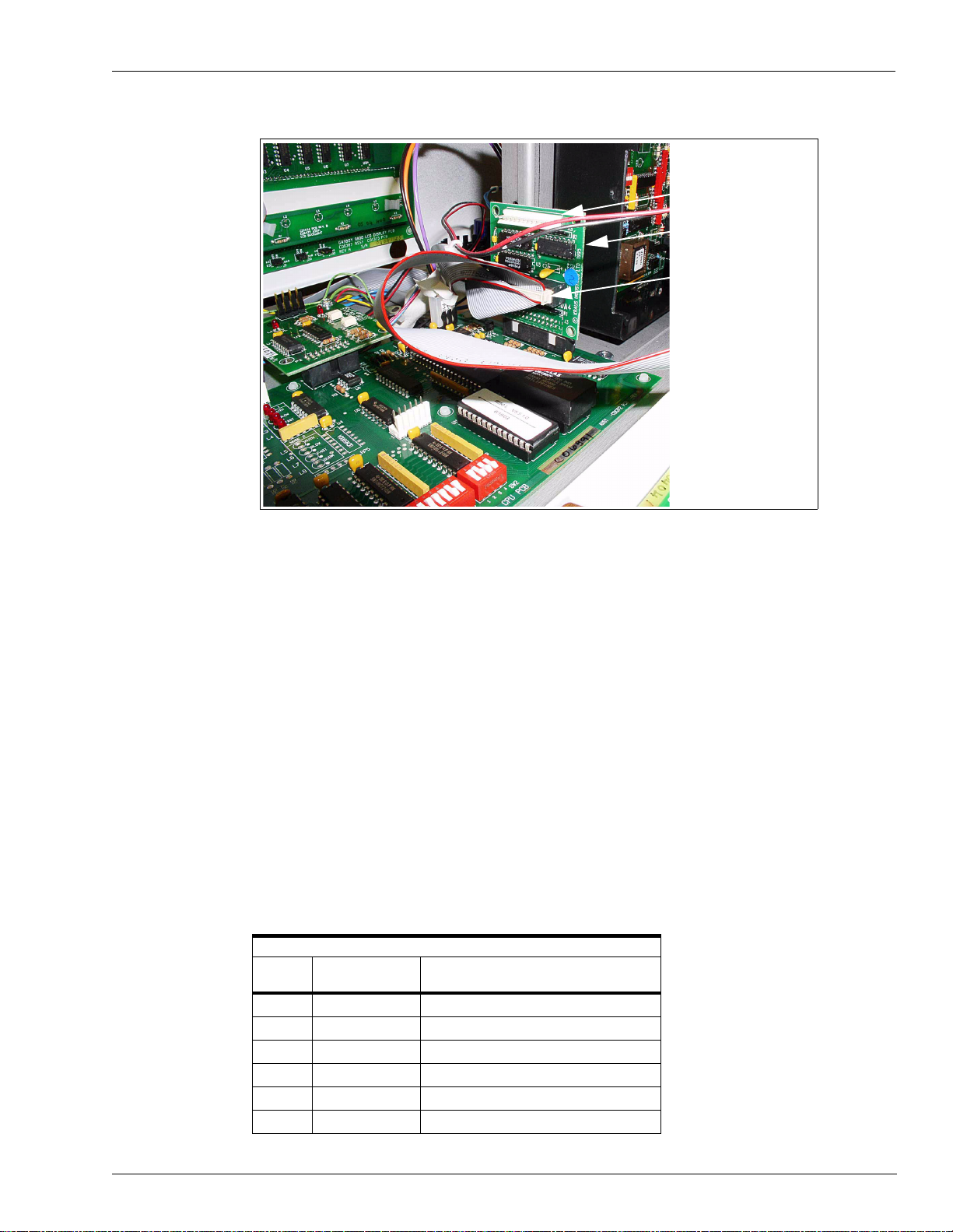
Figure 20: 460A4 Circuit Board in Place with Connections Made
J4
460A4 Circuit
Board Assembly
W283 Display Adapter
Connector on J4
Installation
19
In the kit, loc ate the W172 3-wire harness for IS Barrier.
20 Place the connector on the harness on P5 of the LP-70 Polycase box (Figure 19).
21 Using three of the crimp splices, connect the wires of the harness to the wires extending from
the top of th e IS barrier. Match co lor codes.
22 Connect the ground wire (wire with eyelet connector) to the nearest true ground.
23 Disconnect cable going to P6 connector of the Pump CPU board.
24 Connect the cable that was disconnected in previous step to P9 connector in the LP-70
Polycase box.
25 If the user wants to be able to display electronic totals, a second cable (C06003) must be
installed and connected to the P6 connector on the Pump CPU board.
26 In the LP-70 Polycase box, locate the DIP switches shown in Figure 19 and set the switches
for the proper unit as shown in the following table:
DIP Switch Settings
Switch
Number Switch Function Settings
1 Product 1 ON for Diesel, OFF for Gasoline
2 Product 2 ON for Diesel, OFF for Gasoline
3 Not used N/A
4 Not used N/A
5 Pulser Multiplier ON for 9850, OFF for 9852/9853
6 Number of Probes ON for two (2) probes, OFF for one (1) probe
MDE-4351A Gasboy ATC Kits 039086 and 039087 Installation Manual • February 2006 Page 21
Page 22
Installation
DIP Switch Settings
Switch
Number Switch Function Settings
7 Pulser Adder ON for 9840
8 ATC ON for ATC ON, OFF for ATC OFF
27 Remount the LP-70 Polycase box cover removed in step 1.
28 Using two of the crimp splices, connect the two green wires extending from the bottom of the
IS barrier mounting stud to the two green wi res attac hed to the dual probe conn ector assembly.
29 Using two of the crimp spl ices, conne ct the two ye llow wires extending from the bot tom of the
IS barrier mounting stud to the two yellow wires attached to the dual probe connector
assembly.
30 In the kit, locate the foll owing: (See Figure 1 for parts identity)
• W199 probe assemblies (2)
• BC407 Thermowells (2)
• 235-C Thermowell Plugs (2)
• BC546 Adapters (2)
31 Underneath the shelf (where the IS barrier is mounted), locate the two plugs in the hydraulic
coupling toward the right side of the unit (Figure 21).
Figure 21: Probe Assembly Mounting Location
Plugs
32
Using the appropriate size Allen wrench, remove the two plugs.
Page 22 MDE-4351A Gasboy ATC Kits 039086 and 039087 Installation Manual • February 2006
Page 23

CAUTION
Installation
When applying
first free of sealant to prevent the sealant from entering, and possibly damaging or inhibiting
proper operation of, the unit.
33 Using SAF-T-LOK TPS sealant, coat the BC407 Thermowell threads and thread into one of
SAF-T-LO K TPS sealant on threads, leave the two thre ads that enter the hole
the holes where the plugs were removed in the previous step (Figure 22).
Figure 22: Thermowell and Probe Assembly Connections
Probe Assembly
Thermowell Plug
Thermowell
Adapter
34
Using a proper size wrenc h, tig hten th e ther mowell and pl ace the 235-C Ther mowell p lug int o
the thermow ell.
35 Coat the threads of the BC546 Adapte r with SAF-T-LOK TPS sealant and turn it into th e other
hole where the plugs were removed in step 32 (see Figure 22).
36 Coat the threads of the W199 Probe Assembly with SAF-T-LOK TPS sealant and turn it into
the BC546 a dapter mounted in the previous step.
37 Using the proper size wrench, tighten both the adapter and probe.
CAUTION
Be sure the threads on the thermowell, adapter, and probe assembly are properly
coated with the SAF-T-LOK TPS sealant and tightened properly to prevent leaks
.
MDE-4351A Gasboy ATC Kits 039086 and 039087 Installation Manual • February 2006 Page 23
Page 24

Installation
38 Connect the other end (connector) of the probe to probe connector assembly in the connector
labeled “1”.
39 Locate the other two plugs in the hydraulic coupling toward the left side of the unit (Figure
21).
40 Repeat Steps 29 through 34 to mount the second probe assembly.
41 Connect the connector end of the second probe to probe connector assembly in the connector
labeled “2”.
42 Go to “Completing Installation” on page 24 in this manual.
Completing Installation
1 Dress the cabling by placing them in existing cable ties. Be sure the cables do not create any
obstruction to operation, access or servicing.
2 Test the ATCs to determine that they are functioning properly.
This will involve r unning transactions and using the totalizer display (see Appendix: Totalizer
Display Info rmation).
3 After determining that the ATCs are functioning properly, remount the doors on both sides of
the unit and secure with the keylocks.
4 Inform the manager/owner that the unit can be returned to service.
Page 24 MDE-4351A Gasboy ATC Kits 039086 and 039087 Installation Manual • February 2006
Page 25
Appendix: Totalizer Display Information
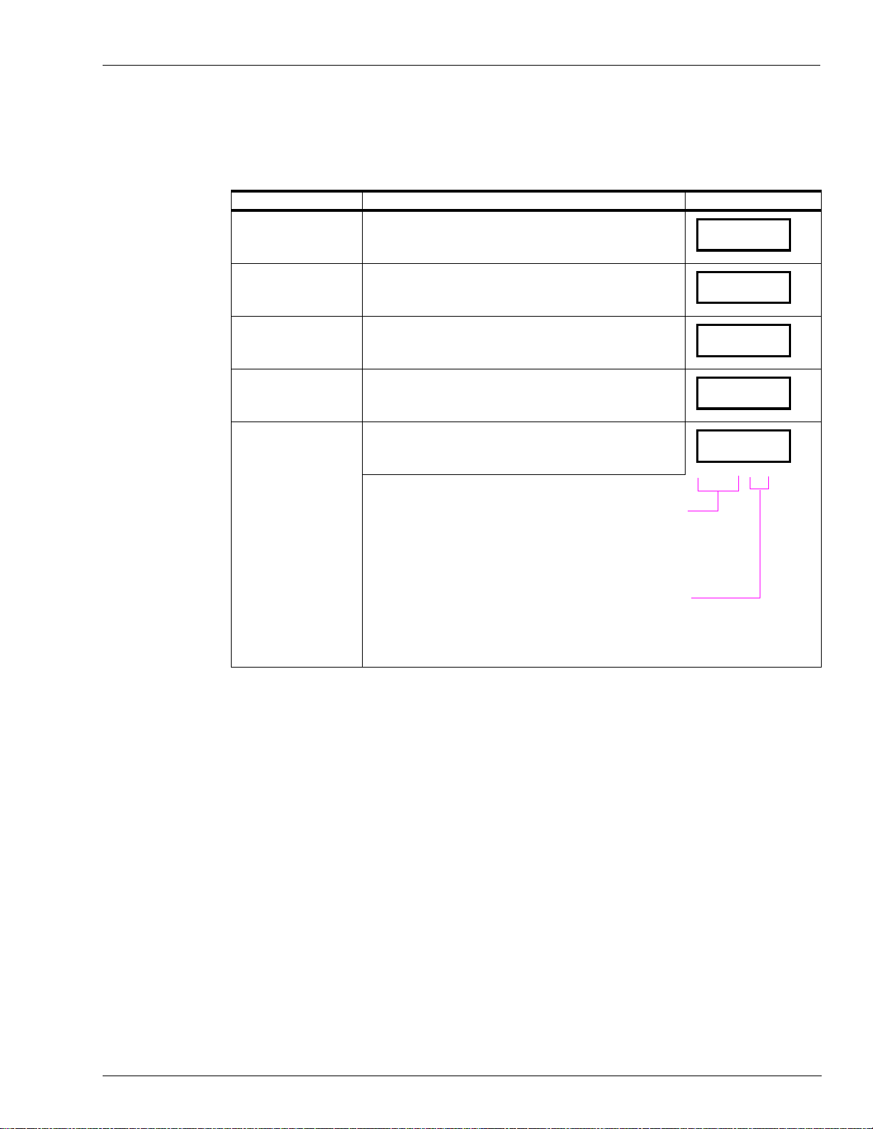
By activating the magnet located at the opposite side of the totalizer, various information will
appear on the display as follows:
Information Type Definition Example of Display
Volume Displays uncompensated volume
Appendix: Totalizer Display Information
0023.43
Probe Temperature Displays probe temperature (in Celsius only)
Flow Rate Displays flow rate (in LPM only)
Software Version Displays software version number
ATC Status Displays ATC status
Leftmost digits (842) are error indicators which are blank when
the corresponding error condition is not active.
8 = temperature probe fault detected
4 = pulser error occured
2 = exceptional reset detected
Rightmost digit (2) indicates whether temperature compensation
is enabled, and if so, what product is being dispensed.
0 = temperature compensation disabled
1 = product is gasoline and compensation enabled
2 = product is diesel and compensation enabled
0 23.2
189.2
1.30
842 .2
MDE-4351A Gasboy ATC Kits 039086 and 039087 Installation Manual • February 2006 Page 25
Page 26

Appendix: Totalizer Display Information
Allen® is a registered trademark of Industrial Fasteners, Inc.
®
Polycase
SAF-T-LOK
Teflon
is a registered trademark of ECP Corporation.
®
is a registered trademark of SAF-T-LOK Chemical Corporation.
®
is a registered trademark of E.I. DuPont de Nemou rs and Company.
© 2006 GASBOY
7300 West Friendly Avenue • Post Office Box 22087
Greensboro, North Carolina 27420
Phone (800) 444-5529 • http://www.gasboy.com • Printed in the U.S.A.
MDE-4351A Gasboy ATC Kits 039086 and 039087 Installation Manual • February 2006
 Loading...