

Page 1

Introduction
Purpose
This manual provides instructions to install the following Seal Installation kits:
• 032867
• 054024
• 054026
• M08781K001
Table of Contents
Topic Page
Introduction 1
Important Safety Information 3
Installing the 032867, 054024, and 054026 Kits
(For 70 Series and 620 Series Pumps)
Installing the M08781K001 Kit (For Model 25-28
Series Pumps)
MDE-4449B
Seal Installation Kits 032867, 054024, 054026,
and M08781K001 Installation Instructions
July 2008
5
6
Required Tools
The following tools are required for the installation of the kits:
Parts List
The following table lists the parts included in the 032867 kit.
Item Description Part Number Quantity
1 O-Ring 3/8 X 1/2 -012 Vit 048845 1
2 O-Ring 9/16 X 11/16 -015 048846 1
3 Seal Ring 054131 1
4 Rotating Seal Ring 054133 1
5 Spring 057393 1
6 Washer 067166 1
7 Poly Bag 3 X 5 047400 2
8 Manual, Seal Installation MDE-4449 1
•Pliers
• Flat blade screwdriver
• Snap Ring Pliers
• 9/16” wrench
MDE-4449B Seal Installation Kits 032867, 054024, 054026, and M08781K001 Installation Instructions · July 2008 Page 1
Page 2

Introduction
The following table lists the parts included in the 054024 kit.
Item Description Part Number Quantity
1 Spring - Seal 057956 1
2 Washer, AL 41/64 X 51/64 067210 2
3 O-Ring .612 I.D.X.103W -1 048941 1
4 Ring-Rotating Sealing 049510 1
5 Ring-Sealing 048820 1
6 O-Ring 11/16 X 7/8 Viton 048956 1
7 Poly Bag 3 X 5 047400 2
8 Manual, Seal Installation MDE-4449 1
The following table lists the parts included in the 054026 kit.
Item Description Part Number Quantity
9 Spring-600 Series Seal 057955 1
10 Washer, AL 41/64 X 51/64 X 067210 2
11 O-Ring .612 I.D.X.103 W -1 048941 1
12 Ring-Rotating Sealing 049510 1
13 Ring-Sealing 048820 1
14 O-Ring .737 I.D. X .103 W -1 048971 1
15 Poly Bag 3 X 5 047400 2
16 Manual, Seal Installation MDE-4449 1
Warranty
The following table lists the parts included in the M08781K001 kit.
Item Description Part Number Quantity
1 Spring M08745B001 1
2 Washer 067210 2
3 Rubber Seal M08511B001 1
4 Rotating Ring 049510 1
5 Seal Ring 048820 1
6 Rubber Seal Boot M08508B001 1
7 Woodruff Key 031375 2
8 Locator Pin 054535 2
9 Retaining Ring K76238-65 1
10 Inner Pump Head (Red)* M08504B001PG8 1
Inner Pump Head (White) M08504B001PN1
Inner Pump Head (Beige) M08504B001PN2
11 Poly Bag 3 X 5 047400 2
12 Manual, Seal Installation MDE-4449 1
* The red colored Inner Pump Head is provided in the kit by default. If other colors are
required (white or beige), they must be ordered separately.
For information on warranty, refer to MDE-4255 Gasboy’s Warranty Policy Statement. If you
have any warranty-related questions, contact Gasboy’s W arranty Department at its Greensboro
location.
Page 2 MDE-4449B Seal Installation Kits 032867, 054024, 054026, and M08781K001 Installation Instructions · July 2008
Page 3
Important Safety Information
This section introduces the hazards and safety precautions
associated with installing, inspecting, maintaining or servicing
this product. Before performing any task on this product, read
this safety information and the applicable se cti on s in th is
manual, where additional hazards and safety precautions for
your task will be found. Fire, explosion, electrical shock or
pressure release could occur and cause death or serious
injury, if these safe service procedures are not followed.
Preliminary Precautions
You are working in a potentially dangerous environment of
flammable fuels, vapors, and high voltage or pressures. Only
trained or authorized individuals knowledgeable in the related
procedures should install, inspect, maintain or service this
equipment.
Emergency Total Electrical Shut-Off
The first and most important information you must know is
how to stop all fuel flow to the pump/dispenser and island.
Locate the switch or circuit breakers that shut off all power to
all fueling equipment, dispensing devices, and Submerged
Turbine Pumps (STPs).
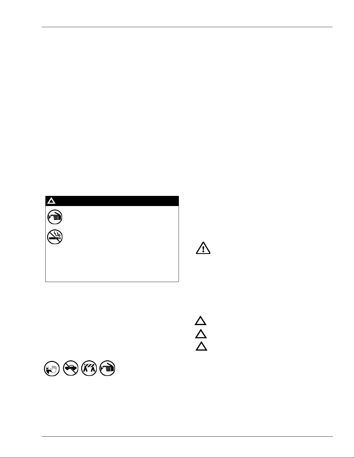
!
WARNING
!
The EMERGENCY STOP, ALL STOP, and
PUMP STOP buttons at the cashier’s station
WILL NOT shut off electrical po wer to th e pump/
dispenser. This means that even if you activate
these stops, fuel may continue to flow
uncontrolled.
Important Safety Information
Read the Manual
Read, understand and follow this manual and any other
labels or related materials supplied with this equipment. If you
do not understand a procedure, call a Gasboy Authorized
Service Contractor or call the Gasboy Service Center at 1800-444-5529. It is imperative to your safety and the safety of
others to understand the procedures before beginning work.
Follow the Regulations
Applicable information is available in National Fire Protection
Association (NFPA) 30A; Code for Motor Fuel Dispensing
Facilities and Repair Garages, NFPA 70; National Electrical
Code (NEC), Occupational Safety and Hazard Association
(OSHA) regulations and federal, state, and local codes. All
these regulations must be followed. Failure to install, inspect,
maintain or service this equipment in accordance with these
codes, regulations and standards may lead to legal citations
with penalties or affect the safe use and operation of the
equipment.
Replacement Parts
Use only genuine Gasboy replacement parts and retrofit kits
on your pump/dispenser. Using parts other than genuine
Gasboy replacement parts could create a safety hazard and
violate local regulations.
Safety Symbols and Warning Words
This section provides important information about warning
symbols and boxes.
Alert Symbol
You must use the TOTAL ELECTRICAL SHUTOFF in the case of an emergency and not the
console’s ALL STOP and PUMP STOP or
similar keys.
Total Electrical Shut-Off Before Access
Any procedure that requires access to electrical components
or the electronics of the dispenser requires total electrical
shut off of that unit. Understand the function and location of
this switch or circuit breaker before inspecting, installing,
maintaining, or servicing Gasboy equipment.
Evacuating, Barricading and Shutting Off
Any procedure that requires access to the pump/dispenser or
STPs requires the following actions:
• An evacuation of all unauthorized persons and vehicl es
from the work area
• Use of safety tape, cones or barricades at the affected
unit (s)
• A total electrical shut-off of the affected unit (s)
This safety alert symbol is used in this manual and
on warning labels to alert you to a precaution which must be
followed to prevent potential personal safety hazards. Obey
safety directives that follow this symbol to avoid possible
injury or death.
Signal Words
These signal words used in this manual and on warning
labels tell you the seriousness of particular safety hazards.
The precautions below must be followed to prevent death,
injury or damage to the equipment:
DANGER: Alerts you to a hazard or unsafe practice
!
which will result in death or serious injury.
WARNING: Alerts you to a hazard or unsafe practice
!
that could result in death or serious injury.
CAUTION with Alert symbol: Designates a hazard or
!
unsafe practice which may result in minor injury.
CAUTION without Alert symbol: Designates a hazard
or unsafe practice which may result in property or
equipment damage.
Working With Fuels and Electrical Energy
Prevent Explosions and Fires
Fuels and their vapors will explode or burn, if ignited. Spilled
or leaking fuels cause vapors. Even filling customer tanks will
cause potentially dangerous vapors in the vicinity of the
dispenser or island.
MDE-4449B Seal Installation Kits 032867, 054024, 054026, and M08781K001 Installation Instructions · July 2008 Page 3
Page 4

Important Safety Information
No Open Fire
Open flames from matches, lighters, welding
torches or other sources can ignite fuels and their vapors.
No Sparks - No Smoking
Sparks from starting vehicles, starting or using power tools,
burning cigarettes, cigars or pipes can also ignite fuels and
their vapors. Static electricity, including an electrostatic
charge on your body, can cause a spark sufficient to ignite
fuel vapors. Every time you get out of a vehicle, touch the
metal of your vehicle, to discharge any electrostatic charge
before you approach the dispenser island.
Working Alone
It is highly recommended that someone who is capable of
rendering first aid be present during servicing. Familiarize
yourself with Cardiopulmonary Resuscitation (CPR) methods,
if you work with or around high voltages. This information is
available from the American Red Cross. Always advise the
station personnel about where you will be working, and
caution them not to activate power while you are working on
the equipment. Use the OSHA Lockout/ Tagout procedures. If
you are not familiar with this requirement, refer to this
information in the service manual and OSHA documentation.
Working With Electricity Safely
Ensure that you use safe and established practices in
working with electrical devices. Poorly wired devices may
cause a fire, explosion or electrical shock. Ensure that
grounding connections are properly made. Take care that
sealing devices and compounds are in place. Ensure that you
do not pinch wires when replacing covers. Follow OSHA
Lockout/T agout requirements. Station employees and service
contractors need to understand and comply with this program
completely to ensure safety while the equipment is down.
Hazardous Materials
Some materials present inside electronic enclosures may
present a health hazard if not handled correctly. Ensure that
you clean hands after handling equipment. Do not place any
equipment in the mouth.
!
WARNING
The pump/dispenser contains a chemical known to the
State of California to cause cancer.
In an Emergency
Inform Emergency Personnel
Compile the following information and inform emergency
personnel:
• Location of accident (for example, address, front/back of
building, and so on)
• Nature of accident (for example, possible heart attack, run
over by car, burns, and so on)
• Age of victim (for example, baby, teenager, middle-age,
elderly)
• Whether or not victim has received first aid (for example,
stopped bleeding by pressure, and so on)
• Whether or not a victim has vomited (for example, if
swallowed or inhaled something, and so on)
WARNING
!
Gasoline ingested may cause unconsciousness
and burns to internal organs.
Do not induce vomiting.
Keep airway open.
Oxygen may be needed at scene.
Seek medical advice immediately.
WARNING
!
Gasoline inhaled may cause unconsciousness
and burns to lips, mouth and lungs.
Keep airway open.
Seek medical advice immediately.
WARNING
!
Gasoline spilled in eyes may cause burns to eye
tissue.
Irrigate eyes with water for approximately 15
minutes.
Seek medical advice immediately.
WARNING
!
Gasoline spilled on skin may cause burns.
Wash area thoroughly with clear water.
Seek medical advice immediately.
IMPORTANT: Oxygen may be needed at scene if gasoline
has been ingested or inhaled. Seek medical advice
immediately.
WARNING
!
Lockout/Tagout
Lockout/Tagout covers servicing and maintenance of
The pump/dispenser contains a chemical known to the
State of California to cause birth defects or other
reproductive harm.
machines and equipment in which the unexpected
energization or start-up of the machine(s) or equipment or
release of stored energy could cause injury to employees or
personnel. Lockout/Tagout applies to all mechanical,
hydraulic, chemical or other energy, but does not cover
electrical hazards. Subpart S of 29 CFR Part 1910 - Electrical
Hazards, 29 CFR Part 1910.333 contains specific Lockout/
Tagout provision for electrical hazards.
Page 4 MDE-4449B Seal Installation Kits 032867, 054024, 054026, and M08781K001 Installation Instructions · July 2008
Page 5

Installing the 032867, 054024, and 054026 Kits (For 70 Series and 620 Series Pumps)
Installing the 032867, 054024, and 054026 Kits (For 70
Series and 620 Series Pumps)
Notes:1) Before performing pump maintenance or service, refer to “Important Safety
Information” on page 3.
2) Refer to Figure 1 for parts identification and assembly order.
3) Refer to Figure 2 on page 6 for the exploded view of the seal assembly and pump.
Figure 1: Assembly Order of the Parts
Aluminium Ring (All Except 60 and 460 Series)
Brass Ring
Spring
O-Ring
Carbon Seal Ring
Stationary O-Ring
Aluminium Ring
To install the 032867, 054024 or 054026 Seal Installation kit, proceed as follows:
1 Remove the Pump Cover, Rotor, Vanes, and Shaft Key to expose the Mechanical Seal.
2 Remove the entire seal assembly from the shaft. If the pump is so equipped, it may be
necessary to remove a Snap Ring from the shaft prior to removing the seal. Ensure that you do
not scratch the shaft or motor counterbore surfaces when removing old seal parts.
Note: It is critical that the seal part mating surfaces remain clean and dry. Do not touch or
allow oil of any type to contaminate the carbon or brass mating surfaces. If the seal
inadvertently becomes contaminated, both mating surfaces must be carefully cleaned
with a lint-free cloth and methyl alcohol.
3 Carefully install the Stationary O-Ring and the Carbon Seal Ring into the motor counterbore.
4 Install the Brass Ring, O-Ring, Aluminum Washer, Spring, and second Aluminum Washer, in
that order . If the pump is equipped with a Snap Ring, install it at this time.
5 Reassemble the remaining parts.
MDE-4449B Seal Installation Kits 032867, 054024, 054026, and M08781K001 Installation Instructions · July 2008 Page 5
Page 6

Installing the M08781K001 Kit (For Model 25-28 Series Pumps)
Installing the M08781K001 Kit (For Model 25-28 Series
Pumps)
Notes:1) Before performing pump maintenance or service, refer to “Important Safety
Information” on page 3.
2) Refer to Figure 2 for parts identification and the exploded view of the seal assembly
and pump.
Figure 2: Installing the Kit (Exploded View of Seal Assembly and Pump)
Rubber Seal Boot
(M08508B001)
Rotating Ring
(049510)
Rubber Seal
(M08511B001)
Spring
(M08745B001)
Retaining Ring
(K76238-65)
Woodruff Key (031375)
Note: This part is not provided in the
kit. Reuse the existing part.
Seal Ring (048820)
Inner Pump Head (Red)
(M08504B001PG8)
Washers (067210)
To install the M08781K001 kit, proceed as follows:
1 Remove the Pump Cover, Rotor, Vanes, and Shaft Key to expose the Mechanical Seal.
2 Remove the Retaining Ring and entire seal assembly from the shaft.
3 Separate the Pump Block from the Inner Pump Head and Motor assembly. Retain the O-Rings
(049180) for reuse.
Page 6 MDE-4449B Seal Installation Kits 032867, 054024, 054026, and M08781K001 Installation Instructions · July 2008
Page 7

Installing the M08781K001 Kit (For Model 25-28 Series Pumps)
4 Remove the old Inner Pump Head.
Note: Ensure that you do not scratch the shaft or motor counterbore surfaces when removing
the old seal parts.
5 Carefully install the new Inner Pump Head (M08504B001PG8) on the motor shaft.
Note: The Rubber Seal Boot (M08508B001), Seal Ring (048820), and Locator Pins (054535)
are pre-installed in the Inner Pump Head.
6 Reassemble the Pump Block and Inner Pump Head using the new Locator Pins (054535).
Reuse one of the O-Rings (049180) between the Inner Pump Head and Pump Body.
7 Refer to Figure 2 on page 6 to install the new seal parts and secure with Retaining Ring
(K76238-65).
8 Reassemble the Rotor, Vanes, Shaft Key, and Pump Cover . Reuse one of the O-Rings (049180)
between the Pump Body and Pump Cover.
MDE-4449B Seal Installation Kits 032867, 054024, 054026, and M08781K001 Installation Instructions · July 2008 Page 7
Page 8

Installing the M08781K001 Kit (For Model 25-28 Series Pumps)
© 2008 GASBOY
7300 West Friendly Avenue · Post Office Box 22087
Greensboro, North Carolina 27420
Phone 1-800-444-5529 · http://www.gasboy.com · Printed in the U.S.A.
MDE-4449B Seal Installation Kits 032867, 054024, 054026, a nd M08781 K001 Installatio n Instruction s · July 2008
 Loading...