

Page 1

CONGRATULATIONS!
Congratulations for choosing a Gary Fisher® bicycle. We have carefully constructed
your bicycle so that its safety and performance meet the highest standards. Your Gary
Fisher dealer has helped you choose the size and model to meet your personal requirements and has assembled and adjusted it. With proper care and maintenance, your new
Gary Fisher bicycle will give you riding pleasure for years to come.
For parents of young riders not able to read this manual: Take time to explain the
material to your child.
Read Chapter 1 carefully before you ride your new Gary Fisher
bicycle!
• Chapter 1 covers important information concerning safety and bicycle care. This
information will help you and your Fisher avoid injury and damage.
• Chapter 2 provides information about periodic maintenance for your Fisher with
the intervals for upkeep of specific parts of your bike under normal riding conditions.
• Chapter 3 gives basic instructions for inspection, lubrication, and adjustment of
the individual components on your Fisher bicycle.
Because the different models in the Gary Fisher line come with a variety of equipment,
this manual may contain some information which does not apply to your bike. Some
illustrations may vary from actual bicycles as delivered. For the Owner's Manual for the
most current model year, please check the web site listed below. If you have any questions
after reading this manual or the information on the Gary Fisher website, consult your
Fisher dealer.
For some parts we refer you to the part manufacturer’s manual supplied with your
bike covering the specific part. If you did not receive a required manual, get one from
your dealer, or contact us at the phone number or Web site listed below and we’ll send
you one.
Assembly and initial adjustment of your Gary Fisher bicycle require
special tools and skills, so this shall only be done by an authorized
Fisher dealer.
Read Chapters 1 and 2 thoroughly. This will take about 45 minutes but will help
to ensure that your Fisher keeps working properly and safely. Use Chapter 3 as a
reference guide whenever a part of your bike needs routine maintenance, as required in
the Periodic Maintenance Schedule, or whenever something needs repair or adjustment
between routine maintenance periods.
Some maintenance and repair should only be performed by your Gary Fisher dealer. Any
such service will be indicated in this manual. If you have a question or problem which your
Gary Fisher dealer can’t handle, contact us at:
Gary Fisher Bicycles (800) 473-4743
Attn: Customer Service http://www.fisherbikes.com
801 W. Madison Street
Waterloo, Wisconsin 53594
© Copyright Trek Bicycle Corporation 2002
All rights reserved
1
Page 2
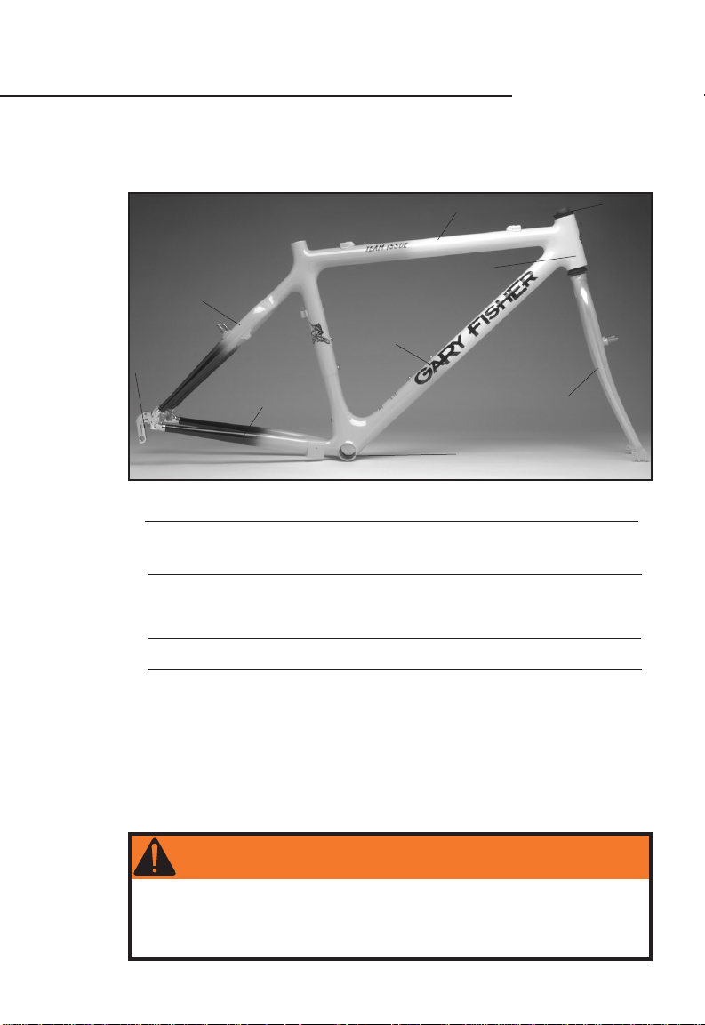
YOUR FISHER BICYCLE
Your Owner’s Manual bag supplied with your bike or frameset includes a warranty card.
You must complete and send this card to Gary Fisher Bicycle Company before we can
process a warranty claim.
We welcome your comments and suggestions. Thank you for buying a Fisher.
Seat stay
Top tube
Head tube
Steerer
(inside the
head tube)
Rear derailleur hanger
Chain stay
Fig. 1
Your bicycle:
Model Name or No. Color Size
Your serial number:
Your bicycle’s serial number is attached to the underside of the down tube, just ahead of the
bottom bracket shell.
Your Gary Fisher dealer:
Phone:
Down tube
Fork blade
Bottom bracket
shell
WARNING
Read Chapter 1 now! It contains important safety information which
you should read thoroughly before you ride your new bicycle.
In this manual, the warning sign indicates there is the possibility of
death or serious injury if an error is made in handling or operation.
2
Page 3

TABLE OF CONTENTS
page
Chapter 1 Guide to Safe Road Riding
Make sure your bicycle fits you properly . . . . . . . . . . . . . . . . . . . . . . . . . . . . . . . . . . . 5
Make sure you are familiar with your bicycle . . . . . . . . . . . . . . . . . . . . . . . . . . . . . . . 5
Make sure your bicycle is in proper working condition . . . . . . . . . . . . . . . . . . . . . . . 6
Check that your wheels are straight. . . . . . . . . . . . . . . . . . . . . . . . . . . . . . . . . . . . . . . 6
Check your tire inflation. . . . . . . . . . . . . . . . . . . . . . . . . . . . . . . . . . . . . . . . . . . . . . . . . 6
Check your brakes . . . . . . . . . . . . . . . . . . . . . . . . . . . . . . . . . . . . . . . . . . . . . . . . . . . . . . 7
Check attachment of both wheels. . . . . . . . . . . . . . . . . . . . . . . . . . . . . . . . . . . . . . . 8-9
Ride safely. . . . . . . . . . . . . . . . . . . . . . . . . . . . . . . . . . . . . . . . . . . . . . . . . . . . . . . . . . 10-12
Ride responsibly off road. . . . . . . . . . . . . . . . . . . . . . . . . . . . . . . . . . . . . . . . . . . . . . . .13
Take care of your bike. . . . . . . . . . . . . . . . . . . . . . . . . . . . . . . . . . . . . . . . . . . . . . . . 14-15
Understand the use of your pedaling system. . . . . . . . . . . . . . . . . . . . . . . . . . . . . 16-17
Child safety and training wheels. . . . . . . . . . . . . . . . . . . . . . . . . . . . . . . . . . . . . . . . . .18
Note: To remove and install your wheels, read
Chapter 2 Periodic Maintenance
Periodic maintenance schedule . . . . . . . . . . . . . . . . . . . . . . . . . . . . . . . . . . . . . . . . . . .19
Recommended tools for proper bicycle maintenance . . . . . . . . . . . . . . . . . . . . . . . 20
Chapter 3 Inspection, Adjustment, and Lubrication
A word about torque specifications . . . . . . . . . . . . . . . . . . . . . . . . . . . . . . . . . . . . . . .21
Handlebars, bar-ends, and stem . . . . . . . . . . . . . . . . . . . . . . . . . . . . . . . . . . . . . . 22-23
Seat and seatpost . . . . . . . . . . . . . . . . . . . . . . . . . . . . . . . . . . . . . . . . . . . . . . . . . . 24-25
Drivetrain- pedals, crank, chain, and cassette . . . . . . . . . . . . . . . . . . . . . . . . . . 26-27
Derailleur shifting systems . . . . . . . . . . . . . . . . . . . . . . . . . . . . . . . . . . . . . . . . . . 28-33
RapidFire shifters . . . . . . . . . . . . . . . . . . . . . . . . . . . . . . . . . . . . . . . . . . . . . . . . . .30-31
Twist shifters . . . . . . . . . . . . . . . . . . . . . . . . . . . . . . . . . . . . . . . . . . . . . . . . . . . . . 32-33
Shimano Nexus 7 speed internal shift system . . . . . . . . . . . . . . . . . . . . . . . . . . . . . 34
Headset and fork . . . . . . . . . . . . . . . . . . . . . . . . . . . . . . . . . . . . . . . . . . . . . . . . . . . . . . 35
Brake systems . . . . . . . . . . . . . . . . . . . . . . . . . . . . . . . . . . . . . . . . . . . . . . . . . . . . . 36-41
Rim brakes . . . . . . . . . . . . . . . . . . . . . . . . . . . . . . . . . . . . . . . . . . . . . . . . . . . . . . . 36-37
Coaster and internal brakes . . . . . . . . . . . . . . . . . . . . . . . . . . . . . . . . . . . . . . . . . . . 38
Rotor and caliper brakes . . . . . . . . . . . . . . . . . . . . . . . . . . . . . . . . . . . . . . . . . . . . . . 39
Disc brakes . . . . . . . . . . . . . . . . . . . . . . . . . . . . . . . . . . . . . . . . . . . . . . . . . . . . . . 40-41
Wheels . . . . . . . . . . . . . . . . . . . . . . . . . . . . . . . . . . . . . . . . . . . . . . . . . . . . . . . . . . . . 42-45
Reflectors . . . . . . . . . . . . . . . . . . . . . . . . . . . . . . . . . . . . . . . . . . . . . . . . . . . . . . . . . . . . 45
Tire installation . . . . . . . . . . . . . . . . . . . . . . . . . . . . . . . . . . . . . . . . . . . . . . . . . . . . 46-47
Front suspension . . . . . . . . . . . . . . . . . . . . . . . . . . . . . . . . . . . . . . . . . . . . . . . . . . . . . . 48
Rear suspension . . . . . . . . . . . . . . . . . . . . . . . . . . . . . . . . . . . . . . . . . . . . . . . . . . . . 50-51
Care of your frame or fork . . . . . . . . . . . . . . . . . . . . . . . . . . . . . . . . . . . . . . . . . . . . . . 49
Trekking accessories . . . . . . . . . . . . . . . . . . . . . . . . . . . . . . . . . . . . . . . . . . . . . . . . 52-53
Gary Fisher Bicycle Company Limited Warranty . . . . . . . . . . . . . . . . . . . . . . . . . . . 60
Important- Read Before You Ride!
Check Attachment of Both Wheels on
pages 8-9 and
Tire Installation on pages 52-53
.
3
Page 4
IMPORTANT! READ BEFORE YOU RIDE
Because a bicycle is smaller and less powerful than other vehicles, safety cannot be
overemphasized. This chapter contains suggestions that will help you ride as safely as
possible. Read this entire chapter before you ride your new Fisher bicycle.
page
Before your first ride
Make sure your bicycle fits you properly. . . . . . . . . . . . . . . . . . . . . . . . . . . . . . . . . . . 5
Make sure you are familiar with your bicycle. . . . . . . . . . . . . . . . . . . . . . . . . . . . . . . . 5
Before every ride: Checklist
Make sure your bicycle is in proper working condition. . . . . . . . . . . . . . . . . . . . . . . 6
Check that your wheels are straight. . . . . . . . . . . . . . . . . . . . . . . . . . . . . . . . . . . . . . . 6
Check your tire inflation. . . . . . . . . . . . . . . . . . . . . . . . . . . . . . . . . . . . . . . . . . . . . . . . . 6
Check your brakes. . . . . . . . . . . . . . . . . . . . . . . . . . . . . . . . . . . . . . . . . . . . . . . . . . . . . . 7
Check attachment of both wheels. . . . . . . . . . . . . . . . . . . . . . . . . . . . . . . . . . . . . . . 8-9
During every ride
Ride safely. . . . . . . . . . . . . . . . . . . . . . . . . . . . . . . . . . . . . . . . . . . . . . . . . . . . . . . . . . 10-12
Ride responsibly off road. . . . . . . . . . . . . . . . . . . . . . . . . . . . . . . . . . . . . . . . . . . . . . . .13
Before, during, and after every ride
Take care of your bike. . . . . . . . . . . . . . . . . . . . . . . . . . . . . . . . . . . . . . . . . . . . . . . . 14-15
Understand the use of your pedaling system. . . . . . . . . . . . . . . . . . . . . . . . . . . . . 16-17
Child safety and training wheels. . . . . . . . . . . . . . . . . . . . . . . . . . . . . . . . . . . . . . . . . .18
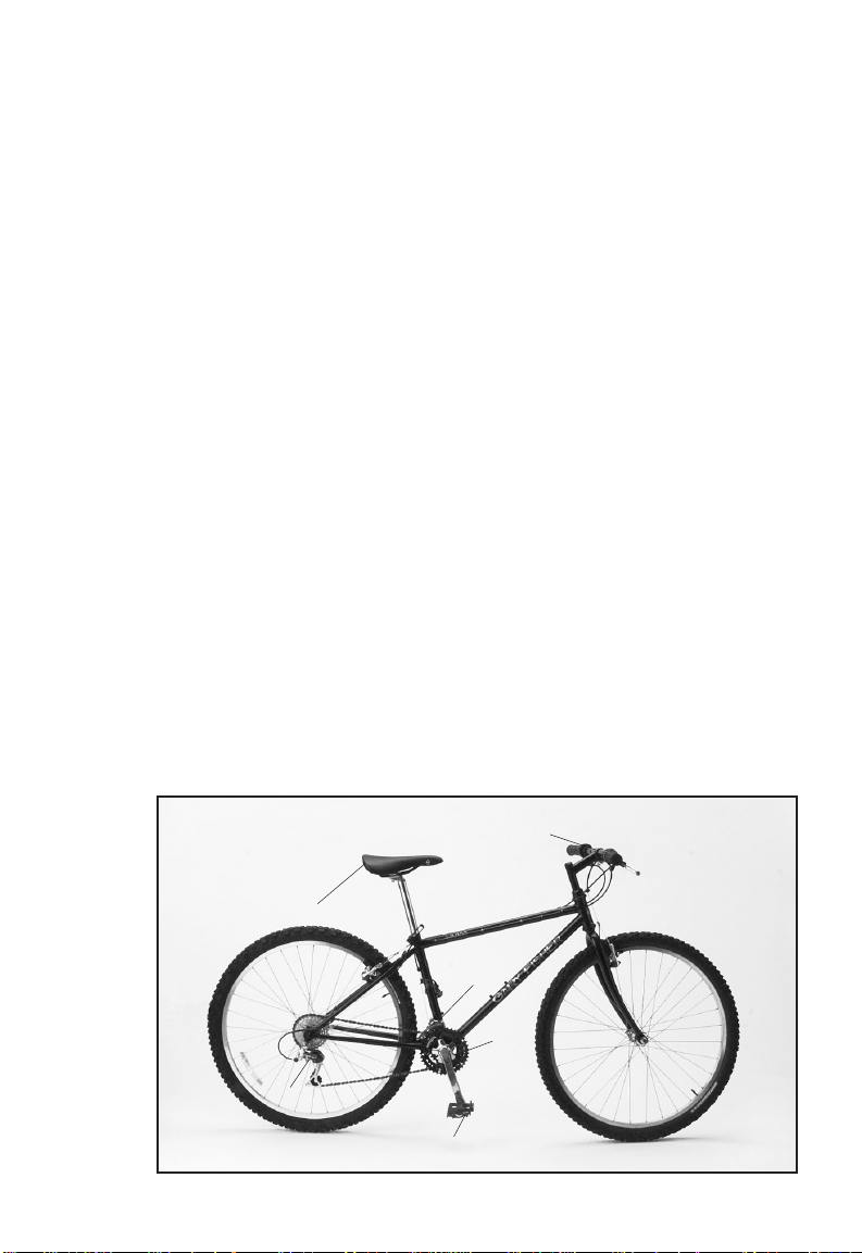
Handlebars
Seat
Front
Wheel
Rear derailleur
4
Fig. 2
derailleur
Crankset
Wheel
Pedal
Page 5
BEFORE YOUR FIRST RIDE
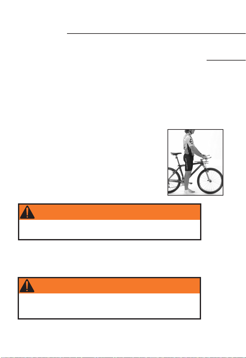
Make sure your bicycle fits you properly.
Your Gary Fisher dealer shall fit you with the proper size of bicycle.
There shall be at least 1 inch (25 mm) clearance between the top tube and the rider
when standing over the bicycle (Fig. 3). For all terrain bicycles we recommend 2-3 inches
(50-75 mm) clearance.
You may also adjust the seat and handlebars to offer the best comfort and performance
possible. Read pages 21 and 22-25 of this manual before attempting to make these adjustments.
Make sure you are familiar with your bicycle.
Your new Fisher bicycle is a wonder of technology. Its mechanisms provide enhanced
control, more efficient pedaling, increased comfort, and great stopping power. However,
these same features, if misused, may cause you to lose control of the bike.
If you would like your bicycle to function differently, or if you have special needs
requiring accommodation for the safe operation of your bike, see your dealer.
Different bicycle designs or models come with brakes chosen from a variety of
brake designs. Different brake designs may have varying amounts of
stopping power. If you are dissatisfied or uncomfortable with your
bicycle's stopping power, consult with your Gary Fisher dealer to discuss
other brake options for your bicycle.
Familiarize yourself with the use of the mechanisms on this bike.
Practice riding the bike at slower speeds in a flat, empty parking lot
before attempting to ride fast or riding in more difficult conditions.
When riding slowly, do not turn the handlebars while the arms of the
crankset (Fig. 2) are parallel to the ground. Modern high performance
bicycles use a short wheelbase design where the front wheel may be
close to the crankset. With this design it is sometimes possible at
very slow speeds for your foot, or toe clips, to contact the front
wheel or fender when the wheel is turned to the side and your foot is
fully forward. At normal riding speeds this does not happen. At slow
speeds, keep your crankarms vertical while turning.
ONE
Guide for
Safe Road
Riding
1 inch
Fig. 3
WARNING
Never allow your foot or toe clip to contact the front wheel or
fender when turning. This may cause loss of control resulting in
personal injury.
In very rare cases some riders, particularly heavier riders on larger bikes, may experience a “shimmy” or “harmonic oscillation” or “frame vibration” at certain speeds. Experts
disagree on what can cause the phenomenon but some believe it may be caused by a
loose headset, improper spoke tension, or frame alignment. Riding “no-hands” or front
wheel impact are among other possible causes. If you believe you are experiencing a
shimmy, slow down immediately and take your bicycle directly to an authorized dealer
for inspection and repair.
WARNING
If you believe you are experiencing a shimmy, slow down immedi-
ately and take your bicycle directly to an authorized dealer for
inspection and repair. Shimmy may lead to loss of control resulting
in personal injury.
A bicycle is both fun and useful. To increase the utility of your bicycle, many accessories
may be added. Make sure any accessories you choose to add to your bike are appropriate
for your riding, and correctly attached so that they are safe. If you are unsure about the
appropriateness or safety of any accessory, consult your Gary Fisher dealer.
5
Page 6
BEFORE EVERY RIDE- CHECKLIST
Make sure your bicycle is in proper working condition.
Spend a few moments before each ride to check your bike’s systems against the
following checklist:
Check that your wheels are straight.
Spin each wheel to check that the rim doesn’t wobble up and down or from side to
side, and that the wheels are centered in the bicycle frame and fork. To do this, watch the
rim as it passes through the brake pads, or the frame. If one or both wheels fail this test,
take your bike to your Gary Fisher dealer for service.
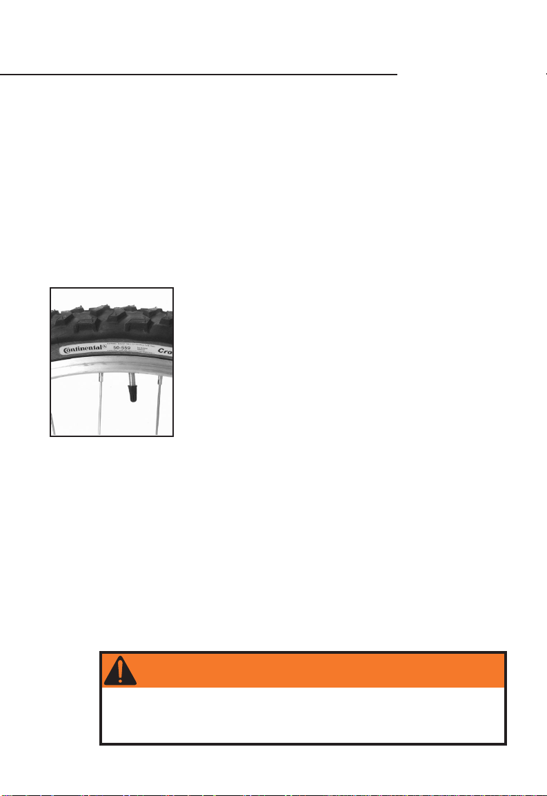
Check your tire inflation.
Inflate your tires to the air pressure recommended on the tire sidewalls
(Fig. 4). Within the recommended range, higher pressures usually give the best performance on hard surfaces like pavement while lower pressures work best for off-road
riding.
Fig. 4
The weight of the rider (and any load) is also a consideration
in selecting tire pressure. Within the recommended inflation rates,
lighter riders may find lower pressures more comfortable, while higher
pressures may better support larger loads or heavier riders and help
prevent pinch flats.
Use a hand-operated pump with an appropriate gauge. Gas station
hoses inflate bicycle tires too rapidly and the pressure they indicate is
often inaccurate.
WARNING
This is not a comprehensive maintenance program. Check the
entire bicycle carefully. If you spot a problem, do not ride the bike
until it has been corrected. If you are not certain if your bike has
a problem, take your bike to your Gary Fisher dealer.
6
Page 7
Check your brakes.
Hand brakes
Press each brake lever to make sure that the brakes move freely and stop the bike. For
bikes with a double pull brake lever, where one lever actuates two brakes, make sure both
brakes work when the brake lever is pressed.
The brake pads should be adjusted so they are 1 to 2 mm away from the rim when
the brakes are not applied. Brake pads should be centered on the rim (Fig. 5). If your
brakes are too tight, too loose, or not centered on the rim, refer to the Brake System
section of Chapter 3.
The toe-in shown in Fig. 5 is to prevent squealing of the brakes. It may not be necessary
to toe in used brake pads, or some new direct pull or V type brakes.
Brake pad aligned with
the rim surface
Pad and rim should be
parallel
Direction of rim
rotation
0.5 - 1 mm toe in
Fig. 5
Disc brakes
For disc brakes, where the pads contact a disc attached to the wheel hub, the pads
should be .25 to .75 mm away from the disc when the brakes are not applied. Always be
careful inspecting disc brakes, as they may become hot after use. As with other rotating
parts on a bicycle, avoid placing your fingers in the disc rotor.
Coaster brakes.
The brakes should engage with less than 60 degrees backwards rotation of the cranks
(1/6 revolution). If your brakes do not firmly engage, take your bike to your Gary Fisher
dealer for service. The chain actuates the brake, so make sure the chain cannot come
off. When grasped in the middle of the chain run between the front and rear sprockets,
there should be between 1/4 and 1/2 inches (6-12 mm) total vertical movement. If the
chain tension is incorrect, refer to the Drivetrain section of Chapter 3.
ONE
Guide for
Safe Road
Riding
Also refer to Use your brakes carefully found on page 11 of this section under
Ride safely.
WARNING
If your brakes are not working properly, do not ride your bicycle.
Refer to the Brake System section of Chapter 3 or take your
bicycle to your Gary Fisher dealer for service.
Initially practice using your brakes at slow speed. Overuse of any
brake system may cause loss of control resulting in personal injury.
Refer to ‘Use your brakes carefully’ and ‘Be careful when riding in wet
conditions’ both found on page 11 of this section under ‘Ride safely.’
Disc brakes, or the cooling fin and hub shell of Shimano Inter-M roller
brakes, may get very hot and could cause burns. Do not touch the
rotor (brake disc), or hub shell, for at least 30 minutes after braking.
7
Page 8
BEFORE EVERY RIDE- CHECKLIST
OPEN
CLOSED
OPEN
CLO
SED
OPEN
OPEN
OPEN
O
PEN
(continued)
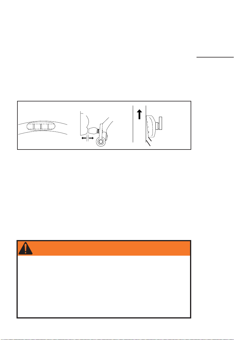
Check attachment of both wheels.
This bicycle may be equipped with a quick
release wheel retention mechanism. The quick
release allows the wheel to be installed and removed
without tools. For proper and safe performance, read
and follow these instructions carefully:
1. Check both wheels of your bicycle before
every ride.
Fig. 6 Fig. 7
Fig. 8 Fig. 9
Fig. 10
Fig. 11
For you techies: If it requires more
than 45 pounds (200 Newton)
force to completely close the quick
release lever, open the lever and
slightly loosen the quick release
adjustment nut. Close the lever
again. If it requires less than 12
pounds (53.4 Newton) force to
begin to open the lever from the
fully closed position, open the lever
and slightly tighten the adjustment
nut. Close the lever again. Try to
pull the lever from the fully closed
position again. Repeat adjustment
if necessary.
Fig. 12
2. Move the quick release lever to the OPEN
position and set the wheel so it firmly touches the
inside of the fork ends.
3. With the lever about halfway between the
OPEN position and the CLOSED position (Fig.
6), tighten the quick release adjusting nut on the
opposite end of the quick release axle until fingertight (Fig. 7).
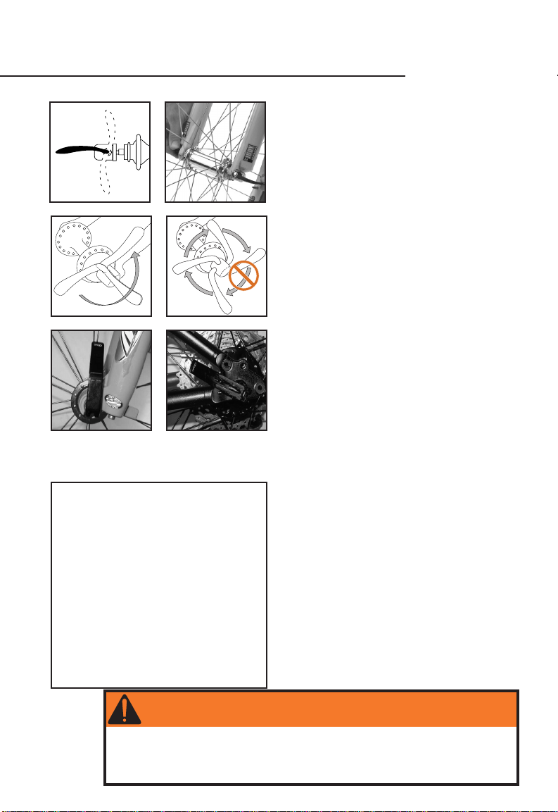
4. Place the quick release lever in the palm of your
hand and move the lever in a motion as shown in
Figure 8. Move the lever into the CLOSED position
(Fig. 10 for a front wheel or 11 for a rear wheel). At the
halfway closed position of the quick release lever, you
should start to feel some resistance to this motion.
5. If the lever is moved to the CLOSED position
with little or no resistance, clamping strength is
insufficient. Simply return the lever to the OPEN
position, tighten the quick release adjusting nut
further and close the lever, testing again for
resistance. When the quick release device is properly
tightened, and clamped to the closed position, the
clamping force is adequate to cause metal into
metal engagement (embossing) of the fork surfaces.
• Do not tighten the quick release by
using the quick release lever like a
wing nut (Fig. 9). This will not result
in sufficient force to hold the wheel
in place. For further information on
correct adjustment of the quick release
tension, read Figure 12.
6. Orient the quick release levers so that they
do not interfere with any other bicycle part or
accessory part (such as rack or fenders) and so
that they will not become accidentally snagged by
obstacles in the path of the bicycle (Figs. 10 and 11).
8
WARNING
Failure to tighten wheel axle nuts, or failure to have wheel quick release
retention mechanisms properly adjusted and closed, may cause loss of
control resulting in personal injury. If you have any questions about the
operation of this system, consult your Gary Fisher dealer.
Page 9
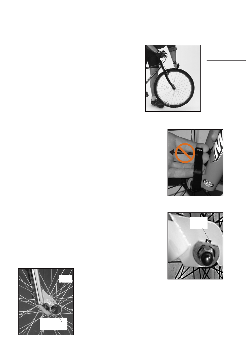
7. Do these two tests to ensure that you have
adequately performed these procedures:
• Pick the front of the bike off of the ground, and
give the top of the tire a sharp downward blow (Fig. 13).
The wheel should not come off, be loose, or move from
side to side. If uncertain, repeat the tightening process,
as shown in Steps 2-6 of these instructions.
• With the quick release lever properly adjusted and
in a closed position, you will not be able to rotate the
quick release lever in a circular motion parallel to the
wheel (as opposed to the flipping motion used to open
and close the quick release lever- see Fig. 14).
8. For the rear wheel, follow the instructions for the
front wheel, and note the correct position of the quick release lever when
closed (Fig. 11).
If your bicycle is equipped with axle nuts instead of quick release
mechanisms (for bikes with pegs, Fig. 16, note special information
below), make sure the axle nuts are tightened to 180-240 lb•in (20.3-27.1
Nm) for a front wheel, and 240-300 lb•in (27.1-33.9 Nm) for a rear
wheel. Use this test to ensure that you have adequately performed
these procedures:
• Pick the front of the bike off of the ground, and give the top
of the tire a sharp downward blow (Fig. 13). The wheel should not
come off, be loose, or move from side to side. Repeat this test
again for the rear wheel.
For the front wheel of children's bikes and BMX bikes with axle nuts,
a special toothed washer must be in place on both sides of the hub
for correct wheel retention (Fig. 15). The toothed washer is placed on
the outside of the fork tip with the tooth in the corresponding hole in
the fork tip.
Some freestyle bikes have tubular axle extensions, called pegs (Fig.
16). For bikes with pegs on the front wheel, the toothed washer must be
against the fork tip as in Fig. 15, with the peg installed over the toothed
washer. Additional washers and nut go inside the peg. For axle nuts in
pegs using a 15 mm socket, tighten to 220-240 lb•in (24.9-27 Nm). For
axle nuts in pegs using a 19 mm socket, tighten to 350 lb•in (40 Nm).
ONE
Guide for
Safe Road
Riding
Fig. 13
Fig. 14
Toothed
washer
Fig. 16
Peg
Axle nut and
washer
Fig. 15
9
Page 10
DURING EVERY RIDE
45
90
RIDE SAFELY
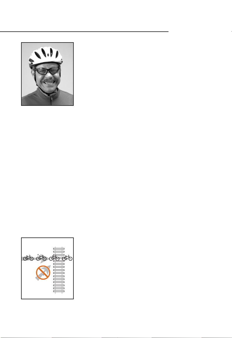
Wear a helmet.
An unprotected head is highly susceptible to injury, even from the
slightest contact. Wear helmets that are comfortable, fit properly, and
meet CPSC or CE safety testing standards (Fig. 17). Eye protection and
appropriate cycling clothes are also recommended. Helmets should be
removed when not riding the bicycle to avoid entrapment in the straps.
Know and observe your local bicycle riding laws.
Most state and local areas have specific laws for cyclists. Local
cycling clubs or your state’s Department of Transportation (or equivalent) should be able to supply this information to you. A few of the more
important rules of riding:
Fig. 17
• Ride on the correct side of the road (never go against traffic).
• Ride single file when riding with other cyclists.
• Ride defensively (expect the unexpected). Remember: You are hard to see, and
although cycling is becoming more and more common, many drivers simply are not
trained to recognize the rights and special considerations of a bicycle rider.
Do not use unsafe riding practices.
While most cycling rules can be classified as common sense, it is still necessary to list a
few of the things you should NOT do on a bicycle.
• Do not ride ‘no hands’. Without a firm grip on the handlebars, the slightest road
imperfection could initiate a wheel shimmy or in other ways cause the front wheel
to turn unexpectedly.
• Do not ride with loose objects attached to the handlebars or any other part of
the bicycle. They could get caught in the wheel spokes, cause the handlebars to turn
unexpectedly, or in other ways cause loss of control.
• Do not ride while intoxicated or while using medications which might make you
drowsy. Bicycles require good coordination to ride in control, and riders must be
alert for hazards.
• Do not ‘ride double’. Standard bicycles are not designed to carry the additional
load of a second rider. They also are much harder to balance, steer and stop with the
additional weight of a second rider.
• Use proper hand signals.
Ride defensively.
Always watch for hazardous situations. Remember, you are not as
visible as a car to other bicyclists, motorists, or pedestrians. Be ready to
stop or take evasive action at all times.
Watch the road.
Watch for potholes, drain grates, soft or low shoulders, and other
deviations. Impact to a wheel, like improper spoke tension, may lead to
wheel collapse causing loss of control. When crossing railroad tracks or
drain grates, do so carefully at a 90° angle (Fig. 18). If you are not sure
of conditions, walk your bike.
Fig. 18
10
If a car you are passing suddenly enters your lane or someone opens a car door
unexpectedly, you could be involved in a serious accident. Mount a horn or bell on your
bicycle for defensive riding.
Watch the parked cars you are preparing to pass.
Page 11
Use your brakes carefully.
Always keep a safe stopping distance between you and other vehicles or objects. Adjust
stopping distances and braking forces to suit riding conditions. If your bike has two hand
brakes, apply both brakes at the same time. Many models of modern brakes are designed
to stop a bike in wet or muddy conditions. Over-use of a powerful front brake, or use of
only the front brake in an emergency situation, could cause the rear wheel to lift from the
ground which could cause serious personal injury. If you feel your brakes are too powerful
for your riding needs, take your bike to your dealer for adjustment.
WARNING
Avoid mis-use of the front brake. Applying sudden or excessive
stopping force with the front brake may cause your rear wheel to
lift off the ground, or your front wheel to slip out from under you,
causing a loss of control resulting in personal injury.
Be careful when riding in wet conditions.
No brakes, whatever their design, work as effectively in wet weather as they do in
dry. Brakes, even when properly aligned, lubricated, and maintained, require greater lever
pressure and longer stopping distances in wet weather. Anticipate the extra time it will
take to stop. Also remember that wet weather causes reduced visibility (both for you and
for motorists) and reduced traction. Use slower cornering when traction is reduced. Wet
leaves and manhole covers are other wet weather hazards.
Do not submerge any bearings of your bicycle.
Bearings allow the parts of a bicycle to rotate smoothly, and water will make them
rust and lose their smoothness. If any bearings on your bicycle get submerged, take your
bicycle to your Gary Fisher dealer for service.
Use special care when off-road riding.
• Never ride a road bike on unpaved trails or off road.
• Wear protective clothing including a helmet, eye protection, and gloves.
• Ride only on the trails.
• When approaching a descent, reduce your speed, keep your weight back and low,
and use the rear brake more than the front.
• Avoid rocks, branches, or depressions.
(continued next page)
ONE
Guide for
Safe Road
Riding
WARNING
Be careful when riding at dusk, night, or in any poor lighting
conditions. Your bicycle is equipped with a full set of reflectors;
keep them clean and in position. As useful as these reflectors are,
remember that they do not help you see, nor do they help you be
seen unless light is directed on them. Use a working headlight and
a tail light when you ride in poor lighting conditions. Also wear
light, bright, and reflective clothing, especially at night, to make
yourself more visible. The important thing is to see and be seen. If
you do any amount of riding at dusk, night, or in any poor lighting
conditions, consult your Gary Fisher dealer to find appropriate
products for added visibility when riding in poor lighting conditions.
11
Page 12
DURING EVERY RIDE
RIDE SAFELY
(continued)
• Be considerate of other trail users. Mounting a bell on your bike will allow you to
sound a friendly warning as you approach others on the trail.
• Read and follow the IMBA Rules of the Trail (page 13).
WARNING
As with any mechanical device, every bicycle, and each part
attached to it, has a limited useful life due to wear and stress.
The length of that life varies according to its design, materials,
maintenance, and use.
A crash may put extraordinary stress on a bicycle or its parts.
Jumping your bicycle, performing bicycle stunts, severe off road
riding, downhill riding, or any abnormal bike riding may be very
dangerous because they increase the stress on your frame.
Industry pictures and videos of these kinds of activities depict
very experienced or professional riders. Frames or components
under high stress may fatigue prematurely which may lead to
premature or sudden failure of your bicycle frame or components.
Such failure could cause a loss of control resulting in serious
injury or death.
It is much easier to have an accident resulting in serious
personal injury in these situations even if your bicycle performs
as intended. Use suitable protective gear, including a certified
bicycle helmet.
Regularly inspect your entire bicycle for signs of stress. If you
choose to jump your bicycle, use it for stunts, or use it in a
severe offroad or downhill environment, carefully inspect your
frame and components for signs of fatigue before and after each
ride. Scratches, cracks, dents, deformation, or discoloration are
signs of stress-caused fatigue. Although lighter frames or parts
may in some cases have a longer life than heavier ones, it should
be expected that light weight, high performance bicycles and parts
require better care and more frequent inspections.
12
Page 13

RIDE RESPONSIBLY OFF ROAD
At Fisher, we follow these IMBA Rules of the Trail when riding our mountain bikes off road.
We hope you will, too. The future enjoyment of our sport depends on good trail manners.
1. RIDE ON OPEN TRAILS ONLY.
Respect trail and road closures (ask if not sure), avoid possible trespass on
private land, and obtain all required permits and authorization. Federal and State
Wilderness areas are closed to cycling. Additional trails may be closed because of
sensitive environmental concerns or conflicts with other users. Your riding example
will determine what is closed to all cyclists!
2. LEAVE NO TRACE.
Be sensitive to the dirt beneath you. Even on open trails, you should not ride
under conditions where you will leave evidence of your passing, such as on certain
soils shortly after a rain. Be careful not to ride during spring thaws or any time
when the weather makes for sensitive trail conditions. Observe the different types
of soils and trail construction; practice low-impact cycling. This also means staying
on the trail and not creating new ones. Be sure to pack out at least as much as
you pack in.
3. CONTROL YOUR BICYCLE.
Inattention for even a second may cause disaster. Excessive speed is dangerous
and threatens people. There is no excuse for it!
4. ALWAYS YIELD TRAIL.
Make your approach known well in advance. A friendly greeting (or bell) is
considerate and works well; startling someone may cause loss of trail access. Show
your respect when passing others by slowing to a walk or even stopping. Anticipate
that other trail users may be around corners or in blind spots.
5. NEVER SPOOK ANIMALS.
All animals are startled by an unannounced approach, a sudden movement, or a
loud noise. This may be dangerous for you, others, and the animals. Give animals
extra room and time to adjust to you. In passing, use special care and follow the
directions of horseback riders. Running cattle or disturbing wild animals is a serious
offense. Leave gates as you found them or as marked.
6. PLAN AHEAD.
Know your equipment, your ability, and the area in which you are riding and
prepare accordingly. Be self-sufficient at all times, keep your bike in good repair, and
carry necessary supplies for changes in weather and conditions. A well-executed trip
is a satisfaction to you and not a burden or offense to others. Keep trails open by
setting an example of responsible cycling for all mountain bicyclists.
7. BE A GOOD NEIGHBOR.
The opportunity to ride on any trail brings with it a responsibility to maintain
the trail, whether it be State or privately owned lands. Volunteer to assist in trail
maintenance. Help your local park ranger, or form a group of your own, to clean and
maintain trails in your area. Pick up trash when you see it. Be kind to other trail
users. Form friendly relationships with hikers, equestrians, other trail users, and the
people who own or manage the land you use.
Dedicated to the appreciation of and access to recreational lands, nonprofit IMBA
welcomes your support. Contact:
ONE
Guide for
Safe Road
Riding
International Mountain Bike Association (IMBA)
P.O. Box 7578 (303) 545-9011
Boulder, CO 80306 FAX (303) 545-9026
www.imba.com
13
Page 14

BEFORE, DURING, OR AFTER EVERY RIDE
TAKE CARE OF YOUR BIKE
Keep your bicycle clean.
To keep your bicycle in proper working condition, keep it clean. If your frame or a
component is dirty, clean it with a soft damp cloth and Wrench Force® bike cleaner or
similar product. If you hear a grinding or “sandy” noise coming from any bearings, your
bearings need maintenance. Take your bicycle to your Gary Fisher dealer for service.
Avoid high pressure washing systems, like those at most car washes. The high pressure
may bypass bearing seals, letting water into the bearings. Water will make the bearings
rust and lose their smoothness.
Avoid leaving your bicycle out in the weather.
When not riding, keep your bike in a location where it will be protected from rain, snow,
sun, etc. Rain and snow may cause your bicycle to corrode. The ultraviolet radiation from
the sun may fade the paint, or crack any rubber or plastic on the bicycle.
Use proper storage for your bicycle.
Improper storage is very hard on a bicycle. Before storing your bike for an extended
period of time, clean and lubricate it, and polish the frame with Wrench Force® frame
polish or a similar frame protectant. Hang the bicycle off the ground with the tires at
approximately half pressure. Do not store near electric motors, as ozone from motors
destroys rubber and paint. Before riding the bicycle again, be certain it is in good
working order.
Protect your bicycle from theft.
• Keep a record of the serial number in a safe place. See page 2 for the location
of the serial number on your bike. Also make sure you return your warranty card; we
will keep your bike’s serial number on file.
• Register the bicycle with your local police department.
• Purchase a lock that is effective against bolt cutters and saws, and follow the
recommended locking procedures.
• Use your lock. Never leave your bike unlocked while unattended, not even for a
minute.
• With quick release wheels, lock both of your wheels as well as your frame. If
you have a quick release seatpost binder, when locking your bike you may want to
remove your seat and seatpost to prevent theft. However, avoid allowing water to
enter your bicycle frame through the open seat tube of your bike.
Use good shifting techniques.
When shifting, reduce the amount of pressure on your pedals. This provides quicker,
smoother shifting and will help avoid bent chains, derailleurs, and chainrings, and will also
help avoid excessive chain and gear wear.
Protect your bike from accidental damage.
Park your bike in a place where it will be out of the way, and make sure it cannot fall
over. Do not lay the bike on its derailleurs, as you may bend the rear derailleur or get
dirt on the drivetrain. Don’t let the bike fall down, as this may cut the handlebar grips, or
tear the seat. Incorrect use of bike racks may bend your wheels, as can riding over some
obstacles. These are just a few of the potential hazards you and your bike may encounter.
If you suspect your bicycle has been damaged or tampered with in any way, ensure that
there is no problem, or take it to your Gary Fisher dealer for inspection and repair.
14
Page 15

Prevent handlebar impact damage to your frame.
With some bicycles it is possible for part, or parts, of the handlebar to contact the frame
as the front wheel turns to extreme angles. If a sharp edge on any part of the handlebar
were to make contact with the frame with sufficient force, it could damage the frame.
Check to see if your handlebar contacts the frame in such a way that this could happen.
Prevent such damage by padding the handlebar parts, the frame, or both at the points of
contact. See your Gary Fisher dealer for recommended protection devices or materials.
Never modify your fork, frame, or components.
Your bike’s parts have been carefully designed to meet the strength and function
requirements of safe riding. Modifying these parts in any way may make your bike unsafe.
As an example, some bike frames have special surface treatments which add strength
and these could be removed through poor paint stripping techniques. Removing the
redundant wheel retention tabs on fork tips or peg-and- eyelet style redundant retention
devices is another example of how modifying a bicycle could make it less functional.
Changing the forks on your bicycle could alter the steering of the bicycle, or create
undesirable stress loads on the frame. Suspension forks may add stress to a bike frame.
Never add a suspension fork to a road bike, or change style and/or length of forks. If
you must replace the fork on any bike, check with your dealer or Fisher Bicycles' technical
service department to ensure that the new forks are compatible with the frame.
Any modification of your frame, fork, or components means that your bike no longer
meets our specifications and will therefore void the bike’s warranty.
Care of your frameset
Fisher bicycles use a variety of materials in the construction of framesets (frame and
fork). Your frameset may require special attention in its care and maintenance. See page
49 for information about your frameset.
ONE
Guide for
Safe Road
Riding
WARNING
Never modify your frameset in any way, including sanding, drilling,
filing, removing redundant retention devices, or by any other
technique. Such modifications will void your warranty, may cause
your frame to fail, and may contribute to loss of control resulting
in personal injury.
15
Page 16
UNDERSTAND THE USE OF YOUR PEDALING SYSTEM
Toe clips and straps.
If this bike came without pedals, you will choose the pedals that are
best for you. Follow the manufacturer’s instructions for installation and
use of these pedals.
This bicycle may be equipped with toe clips and straps. Familiarize
yourself with the use of toe clips and straps. Proper fitting toe clips
place the ball of your foot over the pedal axle for improved pedaling
power. Shoes which might allow your foot to become trapped by the toe
straps, such as those with wide, heavily patterned soles, should never be
used with toe clips and straps.
If you are new to this system, practice entry and exit before your first
ride. Watch the road while in motion. Looking at your pedals will make it
Fig. 19
Fig. 20
difficult to see upcoming obstacles. After first practicing in a stationary
position, a flat, empty parking provides an excellent place to practice
the following:
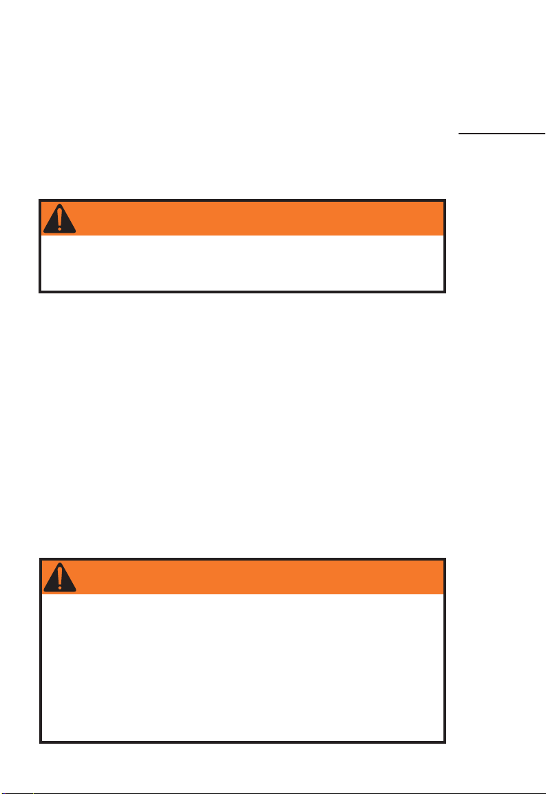
• Always keep toe straps loose enough to remove your feet quickly
from the pedals to remain upright. This is done by adjusting the buckle
of the toe strap (Fig. 19).
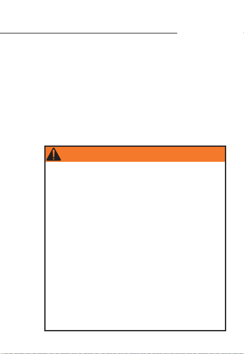
• To enter the pedals, first straddle the bike. Keep your left foot on the
ground, and move the crank arm on the other side of the bike into the
5 o’clock position. To place your foot in the pedal, place the toe of your
shoe on the back edge of the upside down pedal with your toes pointed
slightly downward (Fig. 20). With a motion similar to scraping something
off the bottom of your shoe, flip the pedal into an upright position, and
insert your foot into the toe clip. This can be tricky at first, but practice
will help you improve.
To mount the bike, push down on this pedal while pushing off with the
other foot, and at the same time, sit on the bicycle seat. Once moving,
put your other foot into the second pedal using the same technique.
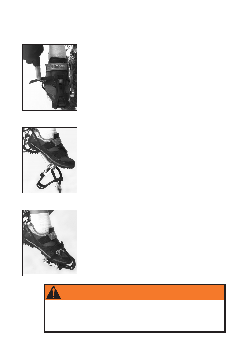
• To exit this system, raise your heel so that the sole of your shoe
clears the top of the pedal (Fig. 21). Withdraw your foot in an up-andback motion, make sure your foot clears the pedal, and bring the bike
to a stop.
16
Always disengage at least one foot from the pedals
before stopping.
Fig. 21
WARNING
Improper use of toe clips and straps may cause loss of control
resulting in personal injury. If you are uncertain about the
operation of this system, consult your Gary Fisher dealer. If your
bicycle has toe clips and they do not fit or you do not want them,
ask your Gary Fisher dealer to remove them.
Page 17
Clipless pedaling foot-retention systems
If this bike came without pedals, you will choose the pedals
that are best for you. Follow the manufacturer’s instructions
for installation and use of these pedals.
This bicycle may be equipped with pedals having a clipless
foot retention system which allows you to firmly attach your
shoe to the pedal without toeclips. Incorrect installation of
the cleats could cause physical injury, so cleat installation
should be done by your Gary Fisher dealer.
In addition, some clipless pedals allow adjustment of the
force required to enter or exit the pedals. For adjustment
information, read the pedal manufacturer’s instructions
supplied with your bike. If you did not receive pedal information, get a copy from your dealer, or contact us and we’ll
send them to you. The following information is only meant to
supplement the pedal manufacturer’s instructions.
Familiarize yourself with the use of these pedals. If you are new to
clipless pedals, practice entry and exit before your first ride.
Watch the road while in motion. Looking at your pedals will make it
difficult to see upcoming obstacles. After first practicing in a stationary
position, an empty, flat parking lot provides an excellent place to
practice the following:
• Before attempting to engage your cleated shoe into the pedal,
always check both the cleats and the pedals for any contamination such
as mud and stones which may interfere with entry or exit of this system,
and remove it.
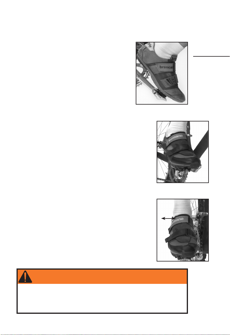
• To enter the first pedal, engage the front of the cleat into the front of
the pedal (Fig. 22) and press down with the ball of your foot. You should
hear an audible click signifying completed entry into the pedal.
Check attachment by attempting a rolling motion on the pedal (Fig.
23). If you can roll your shoe off the pedal, start the procedure again.
To mount the bike, push down on this pedal while pushing off with the
other foot, and at the same time, sit on the bicycle seat. Once moving,
put your other foot into the second pedal using the same technique.
• To exit the system, twist your heel laterally away from the centerline
of the bike (Fig. 24).
Fig. 22
ONE
Guide for
Safe Road
Riding
Fig. 23
Always disengage at least one foot from the pedals
before stopping.
WARNING
Improper use of the clipless pedaling foot-retention system may
cause loss of control resulting in personal injury. If you are uncertain
about the operation of this system, consult your Gary Fisher dealer.
If your bicycle has clipless pedals and you do not want them, ask
your Gary Fisher dealer about other types of pedals.
Fig. 24
17
Page 18

CHILD SAFETY AND TRAINING WHEELS
Learning to ride a bicycle is one of the joys of childhood. Our supervision of young children as they learn about bikes, safety, and cycling
rules of the road is critical to our children’s education. Take the time
to explain the material in this, Chapter 1, to your child as he or she
enters the world of cycling. And instill in your children this cardinal rule
for all cyclists:
Wear a helmet whenever you ride your bike.
Training Wheels
Young children may not be able to ride a bicycle without assistance
of some kind so some models of Fisher bicycles come equipped with
training wheels (Fig. 25). As your child learns to ride a bicycle with
Fig. 25
Fig. 26
training wheels, make sure the child has the skills necessary to stop the
bike. Until this skill is mastered, the child should never ride the bike
without supervision.
The training wheels may be adjusted to promote the learning of skills
such as balancing and turning. To do this, place the bike on a flat,
smooth surface and then check that the tires are correctly inflated.
Follow the procedures in the Drivetrain section of Chapter 3 to loosen
the rear axle nuts. Stand the bike up very straight and then adjust the
training wheels so that there is approximately 1/4 inch (6 mm) between
the training wheels and the ground (Fig. 26). With the bike completely
upright, the training wheels should be evenly spaced from the ground.
Adjust the chain tension and retighten the axle nuts as shown in the
Drivetrain section of Chapter 3, and inspect the wheel attachment as
shown in the Wheels section of Chapter 3. As the child’s skill level
grows, gradually increase the clearance between the training wheels and
the ground until the training wheels are no longer required.
18
Page 19

PERIODIC MAINTENANCE SCHEDULE
Frequency Service Required page
Every ride Check wheel attachment (both) . . . . . . . . . . . . . . . . . . . . . . . . . . . . . . . . . . 42-45
Check tire inflation . . . . . . . . . . . . . . . . . . . . . . . . . . . . . . . . . . . . . . . . . . . . . . . . . . . . 42
Check tires for wear, replace if necessary . . . . . . . . . . . . . . . . . . . . . . . . . . . . . . . . . 42
Check that wheels are straight . . . . . . . . . . . . . . . . . . . . . . . . . . . . . . . . . . . . . . . . . . 42
Check brakes . . . . . . . . . . . . . . . . . . . . . . . . . . . . . . . . . . . . . . . . . . . . . . . . . . . . . . 36-41
Weekly Wipe off your bicycle with a damp cloth . . . . . . . . . . . . . . . . . . . . . . . . . . . . . . . . . .14
Check for loose spokes . . . . . . . . . . . . . . . . . . . . . . . . . . . . . . . . . . . . . . . . . . . . . . . . . 42
Lube suspension forks . . . . . . . . . . . . . . . . . . . . . . . . . . . . . . . . . . . . . . . . . . . . . . . . . 48
Check suspension fork bolts for tightness . . . . . . . . . . . . . . . . . . . . . . . . . . . . . . . . 48
Check rear suspension bolts for tightness . . . . . . . . . . . . . . . . . . . . . . . . . . . . . 50-51
Monthly Inspect and lubricate chain and cassette . . . . . . . . . . . . . . . . . . . . . . . . . . . . 26-27
Inspect and lubricate derailleurs . . . . . . . . . . . . . . . . . . . . . . . . . . . . . . . . . . . . . . 28-33
Inspect for any loose nuts or bolts:
Seatpost binder lever or bolt . . . . . . . . . . . . . . . . . . . . . . . . . . . . . . . . . . . . . . . . . . 24
Seat fixing bolt . . . . . . . . . . . . . . . . . . . . . . . . . . . . . . . . . . . . . . . . . . . . . . . . . . . . . . 24
Handlebar stem expander bolt . . . . . . . . . . . . . . . . . . . . . . . . . . . . . . . . . . . . . . . . . 22
Direct connect stem steerer clamp bolts . . . . . . . . . . . . . . . . . . . . . . . . . . . . . . . . 22
Handlebar clamp bolt . . . . . . . . . . . . . . . . . . . . . . . . . . . . . . . . . . . . . . . . . . . . . . . . . 22
Disc brake, adapter, and rotor attachment bolts . . . . . . . . . . . . . . . . . . . . . . . 40-41
Trekking accessory bolts . . . . . . . . . . . . . . . . . . . . . . . . . . . . . . . . . . . . . . . . . . . 52-53
Inspect shift cables for wear . . . . . . . . . . . . . . . . . . . . . . . . . . . . . . . . . . . . . . . . . 28-35
Inspect brake cables and hydraulic hoses for wear . . . . . . . . . . . . . . . . . . . . . . 36-41
Check wheel bearing adjustment . . . . . . . . . . . . . . . . . . . . . . . . . . . . . . . . . . . . . . . . 42
Check headset bearing adjustment . . . . . . . . . . . . . . . . . . . . . . . . . . . . . . . . . . . . . . 35
Every 3 Months Clean and polish finish . . . . . . . . . . . . . . . . . . . . . . . . . . . . . . . . . . . . . . . . .14
Inspect and lubricate brake levers . . . . . . . . . . . . . . . . . . . . . . . . . . . . . . . . . . . . 36-41
Inspect crankset . . . . . . . . . . . . . . . . . . . . . . . . . . . . . . . . . . . . . . . . . . . . . . . . . . . 26-27
Inspect pedals and toeclips . . . . . . . . . . . . . . . . . . . . . . . . . . . . . . . . . . . . . . . . . . 26-27
Inspect reflectors . . . . . . . . . . . . . . . . . . . . . . . . . . . . . . . . . . . . . . . . . . . . . . . . . . . . . 45
Every year Re-grease bottom bracket bearings . . . . . . . . . . . . . . . . . . . . . . . . . . . . . . . . . 27
Re-grease wheel bearings . . . . . . . . . . . . . . . . . . . . . . . . . . . . . . . . . . . . . . . . . . . . . . 45
Re-grease headset bearings . . . . . . . . . . . . . . . . . . . . . . . . . . . . . . . . . . . . . . . . . . . . 35
Re-grease pedal threads and bearings . . . . . . . . . . . . . . . . . . . . . . . . . . . . . . . . . . . . 27
Lubricate wheel quick releases . . . . . . . . . . . . . . . . . . . . . . . . . . . . . . . . . . . . . . . . . . 45
Lubricate seatpost . . . . . . . . . . . . . . . . . . . . . . . . . . . . . . . . . . . . . . . . . . . . . . . . . . . . . 25
Lubricate handlebar stem . . . . . . . . . . . . . . . . . . . . . . . . . . . . . . . . . . . . . . . . . . . . . . 23
Re-grease suspension forks . . . . . . . . . . . . . . . . . . . . . . . . . . . . . . . . . . . . . . . . . . . . . 48
This maintenance schedule is based on normal usage. If you ride your bike more than
average, or in rain, snow, or off road conditions, service your bicycle more often than the
schedule suggests. If any part appears to be malfunctioning, inspect and service it immediately, or consult your Gary Fisher dealer.
TWO
Periodic
Maintenance
19
Page 20

Recommended tools for proper bicycle maintenance:
Torque wrench with lb•in or Nm gradations
2, 4, 5, 6, 8 mm allen wrenches
9, 10, 15 mm open-end wrenches
15 mm box end wrench
Socket wrench, 14, 15, and 19 mm socket
T25 Torx wrench
No. 1 phillips head screwdriver
Bicycle tube patch kit
Bicycle tire pump with gauge
Tire levers
Wrench Force® synthetic chain lube or similar lubricant
Wrench Force® synthetic grease or similar bicycle grease
Wrench Force® frame polish or similar frame protectant
Special high pressure air pump for rear shock or suspension fork
Note: Not all Fisher bikes require all these tools
20
Page 21

INSPECTION, ADJUSTMENT, AND LUBRICATION
page
A word about torque specifications . . . . . . . . . . . . . . . . . . . . . . . . . . . . . . . . . . . . . . .21
Handlebars, bar-ends, and stem . . . . . . . . . . . . . . . . . . . . . . . . . . . . . . . . . . . . . . 22-23
Seat and seatpost . . . . . . . . . . . . . . . . . . . . . . . . . . . . . . . . . . . . . . . . . . . . . . . . . . 24-25
Drivetrain- pedals, crank, chain, and cassette . . . . . . . . . . . . . . . . . . . . . . . . . . 26-27
Derailleur shifting systems . . . . . . . . . . . . . . . . . . . . . . . . . . . . . . . . . . . . . . . . . . 28-33
RapidFire shifters . . . . . . . . . . . . . . . . . . . . . . . . . . . . . . . . . . . . . . . . . . . . . . . . . .30-31
Twist shifters . . . . . . . . . . . . . . . . . . . . . . . . . . . . . . . . . . . . . . . . . . . . . . . . . . . . . 32-33
Shimano Nexus 7 speed internal shift system . . . . . . . . . . . . . . . . . . . . . . . . . . . . . 34
Headset and fork . . . . . . . . . . . . . . . . . . . . . . . . . . . . . . . . . . . . . . . . . . . . . . . . . . . . . . 35
Brake systems . . . . . . . . . . . . . . . . . . . . . . . . . . . . . . . . . . . . . . . . . . . . . . . . . . . . . 36-41
Rim brakes . . . . . . . . . . . . . . . . . . . . . . . . . . . . . . . . . . . . . . . . . . . . . . . . . . . . . . . 36-37
Coaster and internal brakes . . . . . . . . . . . . . . . . . . . . . . . . . . . . . . . . . . . . . . . . . . . 38
Rotor and caliper brakes . . . . . . . . . . . . . . . . . . . . . . . . . . . . . . . . . . . . . . . . . . . . . . 39
Disc brakes . . . . . . . . . . . . . . . . . . . . . . . . . . . . . . . . . . . . . . . . . . . . . . . . . . . . . . 40-41
Wheels . . . . . . . . . . . . . . . . . . . . . . . . . . . . . . . . . . . . . . . . . . . . . . . . . . . . . . . . . . . . 42-45
Reflectors . . . . . . . . . . . . . . . . . . . . . . . . . . . . . . . . . . . . . . . . . . . . . . . . . . . . . . . . . . . . 45
Tire installation . . . . . . . . . . . . . . . . . . . . . . . . . . . . . . . . . . . . . . . . . . . . . . . . . . . . 46-47
Front suspension . . . . . . . . . . . . . . . . . . . . . . . . . . . . . . . . . . . . . . . . . . . . . . . . . . . . . . 48
Rear suspension . . . . . . . . . . . . . . . . . . . . . . . . . . . . . . . . . . . . . . . . . . . . . . . . . . . . 50-51
Care of your frame or fork . . . . . . . . . . . . . . . . . . . . . . . . . . . . . . . . . . . . . . . . . . . . . . 49
Trekking accessories . . . . . . . . . . . . . . . . . . . . . . . . . . . . . . . . . . . . . . . . . . . . . . . . 52-53
This chapter includes specific instructions for inspecting your bicycle's parts, and the
intervals for such inspections. If any part fails any inspection, do not ride your bicycle.
Either repair or replace the part, or take your bicycle to your dealer for service. Riding a
bike that requires maintenance is very dangerous.
WARNING
Failure to properly maintain your bicycle may lead to damage to the
bicycle, or a loss of control resulting in personal injury.
THREE
Inspection,
Adjustment
&
Lubrication
A Word About Torque Specifications
Torque is a measurement of the tightness of a threaded fastener such as a screw or
bolt, determined by using a torque wrench. The torque specifications in this manual are
listed to help you determine the correct tightness of parts and their threaded fasteners.
More than anything, these should be used to make sure you do not over tighten the
fasteners. Applying more than recommended torque to a fastener does not provide extra
holding power and may actually lead to damage or failure of a part. For example, over
tightening bar ends may crush a handlebar. Once a part is tight enough to stay tight and
be safe, it rarely does any good to tighten the part any further.
We offer a range of torque specifications. Similar parts in different bikes may require
different torques due to slight differences.
There are simple function tests you should perform to make sure a part is properly
tightened and we list them in this chapter. They should be performed whether a torque
wrench was used or not and will suffice as a test for proper tightness if you do not have
a torque wrench. As an example on pages 22-23 we show a test to determine if a stem is
properly tightened to the fork. Place the front wheel between your knees and try to rotate
the stem by twisting the handlebars from side to side. If the stem does not twist, it is
properly tightened. While this test is somewhat subjective, it places a much greater force
on the system than is required of the stem clamping force in normal riding.
21
Page 22

HANDLEBARS, BAR-ENDS, AND STEM
Stem
expander
bolt
clamp bolts
Fig. 27
Steerer clamp bolts
Handlebar clamp bolts
Fig. 28
Stem expander bolt
Handlebar
clamp bolts
Handlebar
Angle
adjusting
bolt
Introduction
The handlebar assembly is primarily responsible for your ability to steer
and control the bike. In addition, the stem and handlebars work with the
seat to add comfort and efficiency to your cycling.
Inspection
Before each ride carefully inspect your handlebars, stem and bar-ends
for signs of fatigue. Scratches, cracks, dents, deformation, or discoloration are signs of stress-caused fatigue. If any part shows signs of
damage or fatigue, replace the part before riding the bicycle.
Before each ride, check that the handlebar plugs are properly inserted
into both ends of the handlebars, and bar-ends.
Once a month, make sure the stem is in alignment with the front
wheel, and that all stem bolts are tight.
Tighten a stem expander bolt (Figs. 27 and 29) to 175-260 lb•in
(19.8-29.4 Nm). Tighten handlebar clamp bolts (Figs. 27-28) using a 5
or 6 mm allen wrench on road and mountain stems to 100-120 lb•in
(11.3-13.6 Nm) on welded stems, or 150-180 lb•in (17-20.3 Nm) on forged
stems, and 80-100 lb•in (9-11.3 Nm) on 4-bolt BMX stems (Fig. 29).
Tighten handlebar clamp bolts using a 4 mm allen wrench to 45-60 lb•in
(9-11.3 Nm). Tighten steerer clamp bolts on mountain bike or road direct
connect stems (Fig. 28) to 100-120 lb•in (11.3-13.6 Nm). For BMX direct
connect stems tighten steerer clamp bolts to 145 lb•in (16.4 Nm).
Some bikes are equipped with a stem having an adjustable rise, or
angle. With these stems, tighten the angle adjusting bolt (Fig. 27) to
150-170 lb•in (17-20.3 Nm) after first making sure the teeth are correctly
engaged, with the corresponding teeth entered between the teeth of the
mating part.
If you are unsure of which type of stem your bike is equipped with,
consult your Gary Fisher dealer.
Test the security of the handlebars in the stem, and the stem in
the frame, by attempting to twist the handlebars in the stem and by
attempting to turn them from side to side with the front wheel locked
between your knees (Fig. 31). Make sure
that no cables are stretched or pinched by
rotating the handlebars.
Fig. 29
22
Stem wedge
allow your bar-ends to come in contact with objects which
may cause you to lose control of your bicycle. Ensure that
the bar-ends face forward and away from you, the rider, and
that the bar-ends are pointing upwards from the handlebars
at an angle not less than 15° from parallel to the ground.
Once a month tighten your bar-end clamp bolts to 85-125
lb•in (9.6-14.1 Nm) to prevent them from rotating on the handlebars.
Bar-ends
Some Fisher bicycles include handlebar
extensions attached to standard all terrain
handlebars. These grips, or bar-ends (Fig.
30), are designed for climbing only. Never
Bar-end
clamp
bolt
Fig. 30
WARNING
Loose bar-ends, incorrectly positioned bar-ends, or catching bar-ends
on objects may cause loss of control resulting in personal injury.
Page 23

Adjustment
The angle and height of the handlebars is largely a matter of
personal preference blending comfort, efficiency, and balance. Your
hands should be comfortable and be able to easily operate all
controls. If your hands, arms, or shoulders are uncomfortable or
numb you may need to adjust the handlebars or select components
more suitable to your personal needs. Consult your Gary Fisher
dealer if you need help attaining comfort on your bike.
To adjust the angle of the handlebars, loosen the handlebar clamp
bolt(s) on the stem just enough that the handlebars can be rotated in the
stem. Position the handlebars to the desired angle, making sure they are
centered in the stem. After adjustment, follow the procedures and tighten
as shown in Inspection.
To change the handlebar height with a conventional stem (Figs. 27 and
29), loosen the stem expander bolt two to three turns, then tap the top of the stem
expander bolt with a wood or plastic faced mallet to loosen the stem wedge. Adjust the
handlebars to the desired height, and retighten following the procedures and instructions in
Inspection (also note WARNING below).
Adjusting the handlebar height on a direct connect stem (Fig. 28) affects the headset
bearing adjustment. This procedure requires special tools and training so this should only
be done by your Gary Fisher dealer.
Some handlebars have reinforcements in the bar tips to support bar-ends. If your
handlebars have cut marks, do not cut these handlebars to a shorter length than the
marks indicate (580 mm minimum width) because this would remove the reinforcement.
WARNING
Cutting handlebars to be shorter than their intended length could
cause them to be weak resulting in a loss of control resulting in
personal injury.
Lubrication
The stem should be lubricated once a year. To lubricate a conventional
type stem (Figs. 27 and 29), loosen the stem expander bolt two or three
turns, then tap the top of the expander bolt with a wood or plastic faced
mallet to loosen the stem wedge. Remove the stem from the frame. Wipe
the old grease off the stem and clean if necessary. Apply a thin layer of
Wrench Force® synthetic grease or a similar lubrication to the section of
the stem that will be inserted into the frame, including the stem wedge.
Insert the stem into the frame, and follow the Adjustment and Inspection
procedures in this section to re-install your stem.
Lubricate a direct connect stem once a year. This procedure requires
adjustment of the headset bearings so should only be done by your
Gary Fisher dealer.
Minimum
insertion
mark
Fig. 31
THREE
Inspection,
Adjustment
&
Lubrication
Fig. 32
WARNING
If you are unsure of the safety of your handlebar system, do not ride
the bicycle. Take the bicycle to your dealer for adjustments. Never
ride your bicycle with the stem raised above the minimum insertion
mark (sometimes called the maximum height mark, see Fig. 32)
as this may cause loss of control resulting in personal injury or
damage to your bicycle. A minimum of 2 3/4 inches (70 mm) of the
stem must always remain in the frame.
23
Page 24

SEAT AND SEATPOST
Introduction
The seat and seatpost are your primary support on the bike. Their
adjustment is important for your comfort and pedaling efficiency. Ensure
Seat
fixing
bolts
Seatpost
Seatpost
binder bolt
Fig. 33
Seat fixing bolt
Fig. 34
that your position on the bike is correct, comfortable, and that both the
seat and seatpost are securely tightened to hold this adjustment.
Inspection
Inspect the seatpost quick release lever, or seat post binder bolt, and
seat fixing bolt(s) (Figs. 33 and 34) for proper tightness every month.
For quick release levers, with the lever halfway between the OPEN
position and CLOSED position, tighten the quick release adjusting nut on
the opposite end of the quick release axle. Place the quick release lever in
the palm of your hand and move the lever into the CLOSED position. At
the halfway closed position of the quick release lever, you should start to
feel some resistance to this motion. If the lever is moved to the CLOSED
position with little or no resistance, clamping strength is insufficient.
Return the lever to the OPEN position, tighten the quick release adjusting
nut further and close the lever, and test again for resistance.
Check to ensure that the seat is secure by attempting to turn the
seat and seatpost in the frame, and attempt to move the front of the
saddle up and down. If the seat rotates, is loose, or moves up and
down, tighten the binder bolt or quick release, or seat fixing bolts,
and repeat the test. Never engage the seatpost binder lever with the
seatpost out of the frame.
• Tighten seat post binder bolts (Fig. 33) to 85-125 lb•in (9.6-14.1 Nm).
• For seat fixing bolts using a 13 or 14 mm open end wrench (Fig. 34),
tighten to 180-220 lb•in (20.3-24.9 Nm).
• For single seat fixing bolts using a 6 mm allen wrench (Fig. 33),
tighten to 150-250 lb•in (17-28.3 Nm).
• For double seat fixing bolts using a 5 mm allen wrench, tighten to
80-125 lb•in (9.6-14.1 Nm).
• For seatposts with two seat fixing bolts using a 4 mm allen
wrench, tighten to 45-60 lb•in (5-6.8 Nm).
Fig. 35
24
Minimum
insertion
mark
WARNING
Make sure that the minimum insertion mark, also called the
maximum height mark (Fig. 35) remains inside the frame. A
minimum of 2 1/2 inches (64 mm) of seatpost must remain in the
frame. Riding with the seat raised above this height may cause loss
of control resulting in personal injury or damage to your bicycle.
Page 25

Adjustment
Seat angle (tilt) and fore-aft position affect both seat
comfort and handlebar comfort by changing the amount of
pressure placed on the handlebars. The height of the seat
is very important for comfort, safety, and efficiency. With
proper adjustment the right bike seat will be reasonably
comfortable even for long rides. If your saddle is not
comfortable or causes numbness, you may need to
adjust the saddle or select a seat more suitable to your
personal needs. Consult your Gary Fisher dealer if you
need help attaining comfort on your bike.
To adjust the angle of the seat, loosen the seat fixing
bolt just far enough so that the seat can be tilted fore
and aft. Place a straight edge, such as a ruler, across
the top of the seat to see this angle better. The correct
adjustment of this angle is largely a matter of personal
preference; first try riding with this angle parallel to the
ground. For bikes with rear suspension, try tilting the
saddle nose down slightly so that compression of the
rear shock under your body weight (sag) results in a
flat saddle.
The seat may also be moved forward or backward along
the seatpost to increase comfort as well as adjust the distance to the handlebars. After
making these adjustments, retighten the seat fixing bolt as in Inspection.
To check the seat height for greater efficiency such as that required for longer distance
cycling, position the crank arms so they are parallel to the seat tube while someone holds
the bicycle up. Place yourself on the seat in riding position without shoes. Your extended
leg should be straight when your heel rests on the bottom pedal (Fig. 36). The correct
position for you will allow the knee of your extended leg to be bent slightly when wearing
your shoes, in a proper riding position; with the ball of your foot on the pedal. To adjust
the height of the seat, loosen the seatpost binder bolt, or quick release lever, change
the seat height, and re-tighten the seatpost lever or bolt as described in the Inspection
section. Also note the WARNING on the previous page.
Lubrication
Lubricate the seatpost every year. To do this, loosen the seat post quick release lever
or bolt, and remove the seatpost from the frame. Wipe the old grease off the seatpost
and clean if necessary. Apply a thin layer of Wrench Force® synthetic grease or a similar
lubricant to the section of the seatpost that will be inserted into the frame. Insert the
seatpost into the frame, adjust to the proper height, and engage the binder lever or bolt,
as explained in Inspection.
Fig. 36
THREE
Inspection,
Adjustment
&
Lubrication
WARNING
Some medical people believe that extended riding with an improperly adjusted or fitted saddle which does not support your pelvic
area correctly may cause numbness and injury to nerves and
blood vessels. Numbness can be avoided with proper bicycle fit. If
you experience numbness while riding your bicycle, have your Gary
Fisher dealer properly fit your bicycle.
25
Page 26

DRIVETRAIN—PEDALS, CRANK, CHAIN, AND CASSETTE
Cassette
Fig. 37
Fig. 38
26
Introduction
The drivetrain consists of the parts of the bicycle
that transmit power to the rear wheel. This system
includes the pedals (and toeclip assemblies on some
models), the crankset consisting of the left and
right crank arms, the chainrings and bottom bracket
assembly, the chain, and the cassette (Fig. 37). When
the components of this system are working together
properly shifting will be easy, your bike will be quiet,
and its efficiency can reach its maximum. For bikes
equipped with Shimano Nexus 7 speed drivetrains,
also refer to page 39, Shimano Nexus 7 Speed Internal
Shift System.
Chain
Pedal
Crank bolt
Chainring
Inspection
Once a month, inspect the chain and cassette. The chain should be
clean, free of rust, and properly oiled. All links of the chain should
pivot smoothly and without squeaking, and no links of the chain
should be deformed. Just like the chain, keep the cassette as clean
as possible. Cleaning and lubrication procedures are covered in the
Lubrication section. To inspect the cassette or freewheel, take the
chain off and rotate the cassette in your hands. If you hear a grinding
noise or your cassette stops immediately after spinning it, the cassette
may need adjustment or replacement. Take your bicycle to your Gary
Fisher dealer for service.
On single speed bikes, check the chain tension once a month. When
grasped in the middle of the chain run between the front and rear
sprockets, there should be between 1/4 and 1/2 inches (6-12 mm) total
vertical movement (Fig. 38).
attached and correctly aligned once a month. Check the chainguard for looseness. Push
side to side, and tap on it. Any movement or rattling may indicate that the chainguard
is loose. Lift the rear wheel off the ground and rotate the crankarms. Listen for any
sounds which might indicate the crank or chain is rubbing on the chainguard. Realign the
chainguard so that it does not rub, and tighten the attachment bolts firmly so that the
chainguard cannot move.
Every 3 months, inspect your pedals and toeclips. Tighten the pedals into the crank
arms to 350-380 lb•in (40.2-42.9 Nm). Tighten the right pedal by turning the pedal
shaft clockwise, but tighten the left pedal in a counter-clockwise direction. Check that
the pedal bearings are properly adjusted. Rotate and move the pedals right to left
and up and down with your hand. If you feel any looseness or roughness in the pedal
bearings, your pedal needs to be adjusted, re-greased, or replaced by your Gary Fisher
dealer. Make sure your toeclips are securely tightened to the pedal, and that the pedal
reflectors are clean and securely in place.
Every 3 months inspect the crankset, including the left and right crank arms, the bottom
bracket set (spindle and bearing assembly), and the chainrings. For bikes with crank bolts,
tighten the crank bolt on each crank arm to 350-435 lb•in (39.5-49.2 Nm). For bikes with
chainring bolts, tighten the chainring bolts to 50-70 lb•in (5.7-7.9 Nm). Check the bottom
bracket bearing adjustment by first removing the chain from the chainrings, then rotate
the crank so that one of the arms is parallel the seat tube. Put one hand on the crank arm
and one hand on the seat tube and attempt to move the crank arm laterally toward and
away from the seat tube. If the crank feels or sounds loose, the bottom bracket bearings
need to be adjusted by your Gary Fisher dealer.
Next, spin the cranks. If the motion stops abruptly or you hear a grinding noise coming
from the bearings, the bearings need to be adjusted or re-greased by your Gary Fisher
dealer. Also clean the chainrings and inspect them for damage. If the teeth are bent or
broken the chainring should be replaced by your Gary Fisher dealer. Note that on some
On bikes with a chainguard, check that the chainguard is firmly
Page 27

chainrings, a few teeth have a special shape to enhance shifting.
Every 3 months, check your chain for wear with a chain wear gauge or a ruler. Each full
link of a new chain measures one inch. If 12 links of your chain measures 12 1/8 inches or
more, it should be replaced. With good maintenance, a chain usually lasts 1000 to 1500
miles on the road (less on a mountain bike). Replacing the chain takes special tools and
training and should only be done by your Gary Fisher dealer.
Adjustment
Some Fisher bicycles are equipped with clipless pedals which require the installation of
special cleats (provided) on specific compatible shoes which can be purchased from your
Gary Fisher dealer. Incorrect installation of the cleats could cause physical injury, so cleat
installation should be done by your Gary Fisher dealer.
Some clipless pedals allow adjustment of the force required to enter or exit the pedals.
For adjustment information, read the pedal manufacturer’s instructions supplied with your
bike. If you did not receive pedal information, get a copy from your dealer, or contact
us and we’ll send them to you. This information is only meant to supplement the pedal
manufacturer’s instructions.
To adjust the chain tension on a single speed bike, gradually loosen the rear wheel axle
nuts on alternate sides of the wheel, slide the wheel to re-tension the chain, and center
the wheel in the frame. Some models have a chain tensioning device which helps position
the wheel. Follow the wheel Inspection and Adjustment procedures in the Wheels section
to re-install the wheel. Adjusting training wheels is covered on page 18.
Adjustment of any part of the drivetrain including the crankset, bottom bracket
bearings, cassette, pedals, or chain installation requires special tools and training. These
services should be performed by your Gary Fisher dealer.
Lubrication
Once a month, clean the cassette and oil the chain. Always place a rag behind the chain
to avoid getting oil on the rest of the bicycle. Use Wrench Force® synthetic chain lube
or similar lubrication. After oiling your chain, wipe off the excess oil with a rag. See your
Gary Fisher dealer for a recommended oil. To clean the cassette, remove the surface
dirt that gathers around the cog teeth with Wrench Force® degreaser or a similar
solvent, and a brush. Do not use gasoline because it’s too flammable and leaves a greasecontaminating film after evaporating. Cleaning the cassette bearings requires special
tools and should only be done by your Gary Fisher dealer. Do not disassemble the
cassette.
Once a year, regrease the part of the pedal axles that thread into the crank arms.
Note: There are right and left pedals usually denoted by a letter stamped on the end of the
pedal axle or on the wrench flats.
Put the right pedal on the right crank arm and the left pedal on the left crank arm.
To remove the pedals turn the pedal spindle counter-clockwise for the right pedal, but
clockwise for the left pedal spindle. Apply a light coat of Wrench Force® synthetic grease
or a similar lubricant over all the threads, and re-install the pedals on the proper side.
See your Gary Fisher dealer for a recommended grease. Follow the tightening instructions
for pedals in Inspection.
Regrease the pedal bearings and the bottom bracket bearings once a year. These
operations require special tools and training, so they should only be done by your Gary
Fisher dealer.
Note: Some pedal bearings and bottom bracket bearings are permanently sealed and do not
require yearly re-greasing.
THREE
Inspection,
Adjustment
&
Lubrication
27
Page 28

Cable
Cable
clamp
bolt
Fig. 39
Adjusting
screws
Adjusting
barrel
Fig. 40
DERAILLEUR SHIFTING SYSTEMS
Introduction
Adjusting
screws
Cable
clamp
bolt
Cable
position) should promptly move the chain from one gear to the next.
Listen to your bike. A properly adjusted drivetrain and derailleur system is quiet. If an
unusual noise follows any shift, your derailleur cable may need to be adjusted slightly (see
the Adjustment section for your shifter type). If, after adjustment, the noise persists or
grows louder, stop the bicycle and try to locate the noise. If necessary, ask your Gary
Fisher dealer to identify and correct any problems. For more information about your
derailleur system read the following information or see your Gary Fisher dealer.
Some Fisher bikes are equipped with a derailleur system. This system
consists of those parts of the bicycle which allow you to shift gears. The
derailleur system includes the front and rear derailleurs, the shifters or
shift levers, and the shift cables.
The different types of shifters covered here are RapidFire or E-Z Fire
shifters (Fig. 41, with one thumb-activated shift lever and one fingeractivated shift lever, both beneath the handlebars), and twist shifters
(Fig. 42, where shifting is done by rotating a section of the handlebar
grip). See Figures 41-42 to determine which type of shift system you
have. Read the general information listed under (all systems) as well as
the specific information for your type of shifter.
The Shimano Nexus 7 speed shift system (Fig. 43) is not a derailleur
system. See Nexus information on page 34.
Shifting Pointers (all systems)
When shifting gears on a bicycle, plan ahead. Shift gears only when
the pedals and chain are moving forward. Never attempt to shift gears
when stopped or back pedaling. When you shift, reduce your pressure
on the pedals. Excessive chain tension makes shifting difficult. Avoid
shifting when going over railroad tracks or bumpy surfaces. The chain
may not shift properly or may fall off.
The left-hand shift mechanism controls the front derailleur and the
right-hand shift mechanism controls the rear derailleur. Shift only one
lever or shifter at a time. Choose the gear combination most comfortable for riding conditions. You should be able to maintain a constant
rate of pedaling. It is not essential that various gear combinations be
used in sequence.
With modern indexed shifting systems, a movement of the shifter from
one position to the next (or movement of the shifter to the "shift"
28
Lubrication (all systems)
Every month, lubricate all pivot points on both the front and rear derailleurs, including
the derailleur pulleys on the rear derailleur, with Wrench Force® synthetic chain lube or
similar lubrication. Lubricate shift cables whenever they are being replaced. Follow the
instructions for shift cable replacement in the following information.
Page 29

Thumb trigger
Finger trigger
Fig. 41 Fig. 42
Fig. 43
THREE
Inspection,
Adjustment
&
Lubrication
29
Page 30

RAPIDFIRE SHIFTERS
Inspection
Once a month, check the shift cables for kinks, rust, broken strands, or frayed ends.
Also check the housing for bent ends, cuts, and wear. If you suspect a problem with your
shift cables, do not ride your bicycle. Replace the cable and/or housing before riding your
bicycle by following the instructions covering adjustment, or take your bicycle to your
Gary Fisher dealer for service.
Once a month, check the operation of the left shift lever/front derailleur. When the left
thumb shift lever is pushed, the front derailleur should shift the chain from a smaller to
a larger chainring. When the left finger shift lever is pushed, the derailleur should shift
the chain from a larger to a smaller chainring. The chain should not fall off the inner or
outer chainrings at any time.
Once a month, check the operation of the right shifter/rear derailleur. When the right
thumb shift lever is pushed, the rear derailleur should shift the chain from a smaller to
a larger cog. When the right finger shift lever is pushed, the rear derailleur should shift
the chain from a larger to a smaller cog. After the shift, the rear derailleur should be
positioned such that it does not rub on the chain. The chain should not fall off the inner
or outer cogs at any time.
Adjustment
Left Shift lever/Front derailleur
To make the low gear adjustment on the front derailleur, first shift the chain onto the
smallest front chainring and the largest cassette cog. Loosen the derailleur cable clamp
bolt until the cable is free. Turn the low gear adjusting screw (usually marked “L”) until the
inner chain guide of the derailleur is approximately 0.5 mm from the chain. While pulling
on the front derailleur cable, push the left finger shift lever several times to ensure that
the shifter is in the small chainring position. Screw the adjusting barrel on the left shifter
to its most clockwise position. Pull the front derailleur cable taut, insert the cable in the
groove found above the derailleur cable clamp bolt, and tighten the cable clamp bolt to
32-52 lb•in (3.6-5.9 Nm).
To make the high gear adjustment on the front derailleur, shift the rear derailleur to
the smallest cog. Next, turn the high gear adjusting screw (usually marked “H”) counterclockwise until it cannot interfere with the motion of the derailleur. While pedaling the
bicycle with your hand, carefully shift onto the outside chainring. Position the front derailleur with the left thumb shift lever so that the outer chain guide of the front derailleur
is approximately 0.5 mm from the chain. Re-tighten the high gear adjusting screw until
it meets resistance. If you have turned it too far, the front derailleur will move toward
the smaller chainring.
30
Right Shift lever/Rear derailleur
To make the high gear adjustment on the rear derailleur, shift the chain onto the
smallest rear cog and the largest front chainring, then loosen the rear derailleur cable
clamp bolt until the cable is free.
Stand behind the bicycle to see that the smallest rear cog, the chain, and the two
derailleur pulleys are in line. If they are not aligned, turn the high gear adjusting screw
(usually marked “H”) until this line is established. While pulling on the rear derailleur
cable, push the right finger shift lever until the shifter is in the small cog position.
Screw the adjusting barrel on the right shift lever to it’s most clockwise position.
Screw the adjusting barrel on the rear derailleur to it’s most clockwise position, and
then rotate it one turn counter-clockwise. Pull the shift cable taut, insert the cable
into the clamp bolt groove on the rear derailleur, and tighten the cable clamp bolt to
32-52 lb•in (3.6-5.9 Nm).
To make the low gear adjustment on the rear derailleur, first turn the low gear adjusting
screw on the rear derailleur (usually marked “L”) far enough counter-clockwise so that it
will not restrict the movement of the derailleur. While pedaling the bicycle with your hand,
carefully shift the chain onto the smallest front chainring and the largest rear cog. Do
not over-shift the rear derailleur, or the chain may wedge between the large cog and
Page 31

the spokes. Position the rear derailleur pulleys in line with the largest cog. Turn the low
gear adjusting screw clockwise until it meets resistance. If you have turned it too far,
the derailleur will move toward the outside of the bicycle. Go through the various gear
combinations. Make sure the chain does not fall off when you shift.
To align the indexing system of your rear derailleur, shift the chain onto the largest front
chainring, and the smallest rear cog. Push the right thumb shift lever to shift the chain
onto the next smallest rear cog. If the chain makes excessive noise or does not shift,
rotate the rear derailleur barrel adjuster counter-clockwise (increasing cable tension) to
align the derailleur pulleys with this second cog. Do this in small increments, until the
system shifts smoothly and quietly. If making this adjustment makes the chain shift to
the third smallest cog, derailleur cable tension is too great. Rotate the barrel adjuster
clockwise until the derailleur pulleys and the second smallest cog is aligned. Go through
the various gear combinations to ensure that the chain smoothly lines up with all the
rear cogs.
To adjust the middle position of the front shifter, shift the chain onto the middle front
chainring and the largest rear cog. Use the barrel adjuster on the front shifter to position
the inner chain guide of the front derailleur approximately 0.5 mm from the chain. Go
through the various gear combinations. Make sure the chain does not fall off when you
shift and that the front derailleur does not rub on any part of the crankset.
If the cable of either derailleur fails the previous inspection, do not ride the bicycle
until the cable has been replaced. To do this, either follow these instructions or take your
bicycle to your Gary Fisher dealer for service. To replace a shift cable, shift the derailleurs
so that the chain is on the smallest front chainring and the smallest rear cog. Note the
path the derailleur cable follows, loosen the derailleur cable clamp bolt holding the bad
cable, and remove the cable through the shifter. Inspect the housings. If they are damaged
or rusty, replace them as well. If you replace any housings, make sure that the pieces are
cut to proper length and of the correct type of housing (use the old pieces as guides) and
that the housing ends are free of burrs; the cable should pass freely through these
ends. Apply Wrench Force® synthetic grease or similar lubricant to the new cable and
feed it through the lever and all of the cable guides and housings, and the cable clamp
following the same path as the old cable. After you have done this, follow the directions
for derailleur adjustment and cut the cable so no more than 2 inches (51 mm) of cable
length extends beyond the cable clamp bolt. To prevent fraying of the cable end, crimp on
a metal cap or apply some solder to the end of the cable.
THREE
Inspection,
Adjustment
&
Lubrication
31
Page 32

TWIST SHIFTERS
Inspection
Once a month, check the shift cables for kinks, rust, broken strands, or frayed ends.
Check the housing for bent ends, cuts, and wear. If you suspect a problem with your
shift cables, do not ride your bicycle. Replace the cable and/or housing before riding by
following these instructions, or take your bicycle to your Gary Fisher dealer for service.
Once a month, check the operation of the left shifter/front derailleur. When the top of
the left shifter is rotated towards you (while on the bike), the front derailleur should shift
the chain from a smaller to a larger chainring. When the top of the left shifter is pushed
away, the derailleur should shift the chain from a larger to a smaller chainring. After the
shift, by moving the shifter slightly, you should be able to position the front derailleur
such that it does not rub on the chain. The chain should not fall off the inner or outer
chainrings at any time.
Once a month, check the operation of the right shifter/rear derailleur. When the top of
the right shifter is rotated towards you, the rear derailleur should shift the chain from a
smaller to a larger cog. When the top of the shifter is pushed away, the derailleur should
shift the chain from a larger to a smaller cog. After the shift, the rear derailleur should
be positioned such that it does not rub on the chain. The chain should not fall off the
inner or outer cogs at any time.
Adjustment
Left Shifter/Front derailleur
To make the low gear adjustment on the front derailleur, first shift the chain onto the
smallest front chainring and the largest cassette cog. Loosen the derailleur cable clamp
bolt until the cable is free. Turn the low gear adjusting screw (usually marked “L”) until the
inner chain guide of the derailleur is approximately 0.5 mm from the chain. While pulling
on the front derailleur cable, rotate the top of the left shifter away to ensure that the
shifter is in the small chainring position. Screw the adjusting barrel on the left shifter
to its most clockwise position. Pull the front derailleur cable taut, insert the cable in the
groove found above the derailleur cable clamp bolt, and tighten the cable clamp bolt
to 32-52 lb•in (3.6-5.9 Nm). To make the high gear adjustment on the front derailleur,
shift the rear derailleur to the smallest cog. Next, turn the high gear adjusting screw
(usually marked “H”) counter-clockwise until it cannot interfere with the motion of the
derailleur.
While pedaling the bicycle with your hand, carefully shift onto the outside chainring.
Position the front derailleur with the shifter so that the outer chain guide is approximately
0.5 mm from the chain. Re-tighten the high gear adjusting screw until it meets resistance.
If you have turned it too far, the derailleur will move toward the smaller chainring. To adjust
the middle position of the front shifter, shift the chain onto the middle front chainring and
the largest rear cog. Use the barrel adjuster on the front shifter to position the inner chain
guide of the front derailleur approximately 0.5 mm from the chain. Go through the various
gear combinations. Make sure the chain does not fall off when you shift and that the front
derailleur does not rub on any part of the crankset.
32
Adjustment
Right Shift lever/Rear derailleur
To make the high gear adjustment on the rear derailleur, shift the chain onto the
smallest rear cog and the largest front chainring, then loosen the rear derailleur cable
clamp bolt until the cable is free. Stand behind the bicycle to see that the smallest rear
cog, the chain, and the two derailleur pulleys are in line.
If they are not aligned, turn the high gear adjusting screw (usually marked “H”) until
this line is established. While pulling on the rear derailleur cable, push the top of the right
shifter away from you as far as it will go. Screw the adjusting barrel on the right shifter to
it’s most clockwise position. Screw the adjusting barrel on the rear derailleur to it’s most
clockwise position, and then rotate it one turn counter-clockwise. Pull the shift cable taut,
insert the cable into it’s groove on the rear derailleur, and tighten the clamp bolt to 32-52
Page 33

lb•in (3.6-5.9 Nm).
To make the low gear adjustment on the rear derailleur, first turn the low gear adjusting
screw (usually marked “L”) far enough counter-clockwise so that it will not restrict the
movement of the derailleur. While pedaling the bicycle with your hand, carefully shift the
chain onto the smallest front chainring and the largest rear cog. Do not over-shift the
rear derailleur, or the chain may wedge between the large cog and the spokes. Position
the rear derailleur pulleys in line with the largest cog. Turn the low gear adjusting screw
clockwise until it meets resistance. If you have turned it too far, the derailleur will move
toward the outside of the bicycle. Go through the various gear combinations. Make sure
the chain does not fall off when you shift.
To align the indexing system of your rear derailleur, shift the chain onto the largest
front chainring, and the smallest rear cog. Rotate the shifter to shift the chain onto the
next smallest rear cog. If the chain makes excessive noise or does not shift, rotate the
rear derailleur barrel adjuster counter-clockwise (increasing cable tension) to align the
derailleur pulleys with this second cog. Do this in small increments, until the system shifts
smoothly and quietly. If making this adjustment makes the chain shift to the third smallest
cog, derailleur cable tension is too great. Rotate the barrel adjuster clockwise until the
derailleur pulleys and the second smallest cog is aligned. Go through the various gear
combinations to ensure that the chain smoothly lines up with all the rear cogs.
If the cable of either derailleur fails the previous Inspection, do not ride the bicycle until
the cable has been replaced. Inspect the housings. If they are damaged or rusty, replace
them as well. If you replace any housings, make sure that the pieces are cut to proper
length and of the correct type of housing (use the old pieces as guides) and that the
housing ends are free of burrs; the cable should pass freely through these ends.
To install a new derailleur cable in a twist shifter, shift the chain to the smallest rear
cog and smallest front chainring. Loosen the derailleur cable clamp bolt on the derailleur
and note the path the cable follows.
Remove the cable through the shifter. Open the small cable window on the shifter
(denoted by a small ‘door’) to expose the leaded end of the cable.
Install the new cable by threading the cable through the shifter. Apply Wrench Force®
synthetic grease or similar lubricant to the new cable and feed it through all of the cable
guides, housings and the cable clamp following the path of the old cable. Reattach and
adjust the derailleur cable as explained in Adjustment. After you have done this, cut the
cable so that there is no more than 2 inches (51 mm) of cable length exposed beyond the
cable clamp bolt. To prevent fraying of the cable end, crimp on a metal cap or apply some
solder to the end of the cable.
THREE
Inspection,
Adjustment
&
Lubrication
33
Page 34

SHIMANO NEXUS 7 SPEED INTERNAL SHIFT SYSTEM
Pulley
Shift cable clamp bolt
Fig. 44
Shift cable barrel
adjuster
Fig. 45
Cable end cover
Cog joint
bracket
Introduction
The Shimano Nexus 7 speed shift system consists of those parts of
the bicycle which allow you to shift gears including the shifter, rear hub,
and shift cable. The shifting mechanism is enclosed, keeping the shifting
system lubricated for low maintenance.
Shifting Pointers
When shifting gears, plan ahead. Shifting gears is best performed
when coasting, stopped, or back pedaling. If you must shift while
pedaling, reduce your pressure on the pedals. Excessive chain tension
makes shifting difficult. Choose the gear most comfortable for riding
conditions. You should be able to maintain a constant rate of pedaling.
Listen to your bike. A properly adjusted shift system is quiet. If
an unusual noise follows any shift, your shift cable may need to be
adjusted. If after adjustment the noise persists or grows louder, stop the
bicycle and try to locate the noise. If necessary, ask your Gary Fisher
dealer to identify and correct any problems. For more information about
your shift system consult your Gary Fisher dealer.
Inspection
Before every ride, make sure the Nexus hub gears are properly
adjusted. With the shifter in 4th gear, the red lines on the hub’s pulley
and the cog joint bracket (Fig. 44) should line up.
Once a month, check the shift cable for kinks, rust, broken strands,
or frayed ends. Also check the housing for bent ends, cuts, broken
coils and wear. If you suspect a problem with your shift cable, do not
ride your bicycle. Replace the cable and/or housing before riding your
bicycle by following these instructions, or take your bike to your Gary
Fisher dealer for service.
Adjustment
If the red lines on the hub’s pulley and the cog joint bracket do not line
up when the shifter is in 4th gear, adjust the gear cable tension. Rotate
the shifter barrel adjuster (Fig. 45) until this alignment is achieved. Shift
to 1st gear, then back to 4th, and recheck the adjustment.
Fig. 46
34
Lubrication
Lubricate shift cables with Wrench Force® synthetic chain lube or
a similar lubricant whenever they are being replaced. Lubricate the
Nexus hub bearings once a year. This procedure takes special tools and
training, so should be done by your Gary Fisher dealer.
To replace the shift cable, loosen the cable fixing bolt and remove the
cover on the front of the shifter secured by a phillips head screw. Slide
the cable end cover (Fig. 46) forward. Note the path of the old cable as
you remove it. Install a new cable in the shifter following the old path,
and reattach the cable fixing bolt. Follow the instructions in Adjustment
to finish installation.
Page 35

HEADSET AND FORK
Introduction
The fork is responsible for holding the front wheel of your bicycle. The
headset (Fig. 47) is the bearing system which allows the steering of your
bike by rotation of the fork, stem, and handlebars.
On freestyle bikes, a rotor (Fig. 48) allows the handlebars to turn 360
degrees for freestyle tricks without interference from the brake cables.
Inspection
Once a month inspect the headset of your bicycle. Stand over the top
tube of your bicycle with both feet on the ground. Apply the front brake
firmly while you rock the bicycle forward and backward. If your bike is
not equipped with a front brake, do this inspection by turning the front
wheel to be across or perpendicular to the pushing force.
Look, listen, and feel for looseness of the headset bearings. To check
that the headset is not too tight, slowly rotate the fork and handlebars
to the right and left.
If the fork makes any grinding noises, or feels like it sticks or binds at any point in the
rotation, the bearings may be too tight. If your headset bearings are too loose or too
tight, do not ride the bicycle. Take it to your Gary Fisher dealer for maintenance.
The rotor should not interfere with the headset function in any way. Look and listen for
irregular noises or rubbing from the rotor.
Adjustment
Headset adjustment requires special tools and training, and should only be performed
by your Gary Fisher dealer. Further adjustment of the rotor is covered in the Brake System
section in the following pages.
Lubrication
Regrea se the headset once eve ry year. This requires special too ls and training, and
should only be performed by your Gary Fisher dealer.
Headset
Fig. 47
THREE
Inspection,
Adjustment
&
Lubrication
Rotor
WARNING
Riding a bicycle with an improperly adjusted headset may cause
loss of control resulting in personal injury.
Fig. 48
35
Page 36

BRAKE SYSTEMS- RIM BRAKES
Cable clamp bolt
Pad
fixing
bolt
Fig. 49
Brake pad aligned with
Fig. 50
Centering
screw
Arm
fixing
bolt
Fig. 51
No contact
Centering
screw
Arm
fixing
bolt
the rim surface
Inspection
Linkwire
Pad
fixing
bolt
Introduction
The brake system allows you to control the speed of your bicycle, and
this function is critical to your safety. Different bicycle designs or models
come with brakes chosen from a variety of brake designs. Different brake
designs may have varying amounts of stopping power. If you are dissatisfied or uncomfortable with your bicycle's stopping power, consult with
your Gary Fisher dealer to discuss other brake options for your bicycle.
The brake system may be difficult to adjust properly without the
proper tools and training. If you are unsure of the brake adjustment,
or suspect any problem, do not ride your bicycle. Take your bicycle to
your Gary Fisher dealer for service. It is strongly recommended that
adjustment of critical components such as brakes be done by your
Gary Fisher dealer. If you need more specific information regarding
your brake system, contact your Gary Fisher dealer
Pad and rim should be
parallel
Before every ride make sure your brakes are working properly and
that the brake pads are in proper position (Fig. 50). Your rims are part of
the braking system, so keep them clean at all times. Check that there is
no oil, grease, or other dirt on the rims.
Every month check your bike’s brake cables and housing. Check the
cables for kinks, rust, broken strands, and frayed ends. Check the
housing for bent ends, cuts, stretched coils, and wear. Replace any part
of your brake cables or housing which do not pass inspection.
Every month, inspect your brake pads for wear. Brake pads have shallow
grooves in their braking surfaces to channel water from the rim. If any
of these grooves are less than 2 mm deep (or 1 mm deep for direct-pull
brakes, Fig. 49), replace the pads.
Every 3 months for direct pull brakes (Fig. 49), cantilever brakes (Fig.
51), or U-brakes (Fig. 52) tighten pad fixing bolts to 70-80 lb•in (7.9-9
Nm). Tighten arm fixing bolts to 70-85 lb•in (7.9-9.6 Nm). Tighten lever
clamp bolts (Fig. 53) to 40-60 lb•in (4.5-6.8 Nm).
Direction of rim
rotation
0.5 - 1 mm toe in
36
Adjustment
Adjust the brake pads so they are 1.5 mm to 2 mm away from the rim when the brakes
are not applied. This is done by turning the brake cable adjusting barrels on the brake
calipers (or brake levers if equipped with direct pull brakes). With a double-pull lever (Fig.
54) adjust the cable tensions so that the rear brake pads are at least as close to the
rim as the front brake pads. To bring the pads closer to the rims, turn the adjusting
barrel counter-clockwise. To move the pads away from the rim, turn the adjusting barrel
clockwise.
If the pads of direct-pull cannot be adjusted close enough to the rim in this manner, loosen
the cable anchor bolt until the cable is loose. Screw the barrel adjuster all the way in clockwise.
Hold the brake pads against the rim, and re-tighten as in Inspection. Changing the brake cable
length in a cantilever brake requires special tools and training, so should only be done by
your Gary Fisher dealer.
To adjust the alignment of the brake pads, loosen the brake pad fixing bolt and align the
pad so that the pad surface and the rim surface meet correctly (Fig. 53). The toe-in shown
in Figure 53 is to prevent squealing of the brakes. It may not be necessary to toe in used
Page 37

brake pads, or some new direct pull or V type brakes.
When adjustment is complete, tighten the pad fixing bolt to 70-80
lb•in. (7.9-9 Nm). To center the brakes, rotate the centering screw (Figs.
49 and 51). After the brakes are adjusted, test the brakes by applying
maximum braking force to the levers. Ensure that the cable does not
slip, that the pads close toward the rim at right angles, and that the
pads do not contact the tire.
If you are unsure of the brake adjustment, or suspect any problem, do not
ride your bicycle. Take your bicycle to your Gary Fisher dealer for
service. It is strongly recommended that adjustment of critical
components such as brakes be done by your Gary Fisher dealer.
Lever clamp bolt
Arm
fixing
bolt
Pad fixing bolt
Fig. 52
Lubrication
Every 3 months, lubricate your brake lever pivots and brake arm
fixing pivots with a light oil. See your Gary Fisher dealer for a
recommended oil. Lubricate brake cables with a thin layer of
Wrench Force® synthetic grease or a similar lubricant when
installed.
Cable Installation
To install a brake cable in a direct-pull brake, note the
path of the old cable, loosen the brake cable anchor bolt
and remove the worn cable. Turn the adjusting barrel on the
brake caliper clockwise so that the threads on the adjusting
barrel are not exposed above the caliper. Grease the new
cable and reinstall, feeding it along the same path as the
old cable. Make sure that the cable’s leaded end is seated
properly in the brake lever body and that the housing
is properly seated in the lever. After threading the cable
through the anchor bolt, follow the directions for brake
adjustment in the Inspection and Adjustment sections.
Finally, cut the cable so that no more than 2 inches (51 mm)
extends beyond the anchor bolt. Crimp a metal cap or place a
bit of solder on the end of the cable to prevent fraying.
Installing a brake cable in a cantilever brake requires
special tools and training, so should only be done by your
Gary Fisher dealer.
Reach adjustment screw
Barrel
Cable
adjuster
Barrel
adjusters
Fig. 53
Fig. 54
Direct-pull Brake Levers
Direct-pull brakes (Fig. 49) have increased leverage and stopping power, and use special
brake levers to manage that power. With all brakes use only levers recognized as compatible,
like those supplied with your bike.
If your direct-pull brake levers offer adjustable braking force, read and follow the
manufacturers instructions supplied with your bike before making any such adjustment.
Like any braking system, failure to properly use and maintain your direct-pull braking
system may result in a loss of control and injury.
THREE
Inspection,
Adjustment
&
Lubrication
WARNING
If you are not certain your brakes are working properly, or you if
suspect a problem with your brake cables do not ride your bicycle.
Refer to the instructions in the appropriate section of this manual
or take your bicycle to your Gary Fisher dealer for service.
37
Page 38

BRAKE SYSTEMS- COASTER AND INTERNAL BRAKES
Fig. 55
Barrel adjuster
Fig. 56
Brake
strap
Brake strap
attachment
Introduction
The brake system allows you to control the speed of your bicycle, and
this function is critical to your safety. Different bicycle designs or models
come with brakes chosen from a variety of brake designs. Different brake
designs may have varying amounts of stopping power. If you are dissatisfied or uncomfortable with your bicycle's stopping power, consult with
your Gary Fisher dealer to discuss other brake options for your bicycle.
The brake system may be difficult to adjust properly without the
proper tools and training. If you are unsure of the brake adjustment,
or suspect any problem, do not ride your bicycle. Take your bicycle to
your Gary Fisher dealer for service. It is strongly recommended that
adjustment of critical components such as brakes be done by your
bolt
Gary Fisher dealer. If you need more specific information regarding
your brake system, contact your Gary Fisher dealer
Inspection- Coaster Brakes
Before every ride check that the brake is working properly by
pedaling backwards. The brakes should engage with less than 60
degrees backwards rotation of the cranks (1/6 revolution). If your
brakes do not firmly engage, take your bike to your Gary Fisher dealer
for service.
If you are unsure of the brake operation, or suspect any problem,
do not ride your bicycle. Take your bicycle to your Gary Fisher dealer
for service. It is strongly recommended that adjustment of critical
components such as brakes be done by your Gary Fisher dealer.
Once a week check that the brake strap attachment bolt is tight and
that the brake strap is securely fastened to the chainstay (Fig. 55).
Inspection- Inter-M Roller Brake
Before every ride, make sure the Nexus Inter-M roller brake (Fig. 56)
brakes should engage enough to stop the bike.
is working properly. After about 15 mm of brake lever movement, the
Adjustment- Inter-M Brake
To decrease the amount of lever travel necessary to engage the brakes, loosen the
barrel adjuster locknut, and rotate the brake cable barrel adjuster (Fig. 56) counterclockwise. To increase lever travel, rotate the barrel adjuster clockwise. Test the lever for
correct travel. When the desired setting is achieved, rotate the barrel adjuster locknut
clockwise until finger tight to hold this adjustment.
Lubrication
Every 3 months, lubricate your brake lever pivots with Wrench Force® synthetic chain
lube or a similar light oil.
Lubricate brake cables with a thin layer of Wrench Force® synthetic grease or a similar
lubricant when installed.
Cable Installation
To install a brake cable in Shimano Inter M brakes, follow the instructions for cable
installation in a rim brake on page 37.
38
Page 39

ROTOR AND CALIPER BRAKES
Introduction
The brake system allows you to control the speed of your bicycle, and
this function is critical to your safety. Different bicycle designs or models
come with brakes chosen from a variety of brake designs. Different brake
designs may have varying amounts of stopping power. If you are dissatisfied or uncomfortable with your bicycle's stopping power, consult with
your Gary Fisher dealer to discuss other brake options for your bicycle.
The brake system may be difficult to adjust properly without the
proper tools and training. If you are unsure of the brake adjustment,
or suspect any problem, do not ride your bicycle. Take your bicycle to
your Gary Fisher dealer for service. It is strongly recommended that
adjustment of critical components such as brakes be done by your
Gary Fisher dealer. If you need more specific information regarding
your brake system, contact your Gary Fisher dealer
Rotor
A rotor (Fig. 58) allows the handlebars on a freestyle bike to rotate 360 degrees despite
having a cable operated front brake. Since the rotor is a connection between the brake
lever and the brake, its function is critical to good stopping power and safety.
Once a month inspect the rotor for proper function. Watch the bearing unit as you
rotate the handlebars 360 degrees. It should not move up or down, or tilt. When the brake
lever is applied, the rotor should apply the brake firmly while the bearing unit remains
parallel to the upper and lower cable stops. If the bearing unit tilts either when the brakes
are applied, or when the handlebars are rotated, the rotor needs adjustment.
To adjust the rotor, first ensure that both lower barrel adjusters are flush with (do
not show above) the lower cable stop, and the bearing unit should be resting on the
lower cable stop. Your rear brake adjustment must be made with the bearing unit in
this position.
The bearing unit should be parallel to the upper and lower cable stops. If it is tilted,
there is slack in one of the cables. Pull each end, one at a time. To see which cable has
slack at the bearing unit. Remove the slack through the barrel adjuster. When even pull is
achieved tighten all barrel adjuster locknuts.
If you are unsure of the brake adjustment, or suspect any problem,
do not ride your bicycle. Take your bicycle to your Gary Fisher dealer
for service. It is strongly recommended that adjustment of critical
components such as brakes be done by your Gary Fisher dealer.
Fig. 57
THREE
Inspection,
Adjustment
&
Lubrication
Caliper brakes
Caliper brakes (Fig. 57) are a rim brake. To install a brake cable in
caliper brakes, follow the instructions for cable installation in a rim
brake on page 37.
Rotor
WARNING
If you are not certain your brakes are working properly, or if you
suspect a problem with your brake cables or hydraulic hose do not ride
your bicycle. Refer to the instructions in the appropriate section of this
manual or take your bicycle to your Gary Fisher dealer for service.
Fig. 58
39
Page 40

BRAKE SYSTEMS- DISC BRAKES
Introduction
The brake system allows you to control the speed of your bicycle, and
this function is critical to your safety. Different bicycle designs or models
come with brakes chosen from a variety of brake designs. Different
brake designs may have varying amounts of stopping power. If you are
dissatisfied or uncomfortable with your bicycle's stopping power, consult
with your Gary Fisher dealer to discuss other brake options for your
bicycle.
The brake system may be difficult to adjust properly without the
proper tools and training. If you are unsure of the brake adjustment,
or suspect any problem, do not ride your bicycle. Take your bicycle to
your Gary Fisher dealer for service. It is strongly recommended that
adjustment of critical components such as brakes be done by your
Gary Fisher dealer. If you need more specific information regarding
Fig. 59
Rotor
your brake system, contact your Gary Fisher dealer
Inspection- Disc Brakes
Before every ride make sure your brakes are working properly. Check that the brake
pads are in proper position. The pads should allow 0.25 to 0.75 mm clearance from
the disc when the brakes are not applied. Spin the wheel. When the brake lever is not
pressed, the brake pads should touch as little as possible on the rotor (disc). Do not
touch disc brake rotors after hard use as they may be very hot.
WARNING
Disc brakes may get very hot and could cause burns. Do not touch
the rotor (brake disc) for at least 30 minutes after braking.
Keep away from moving parts like rotors or spokes. Contact with
moving parts may cause personal injury.
Before every ride squeeze the lever firmly. It should not be possible to
Lever clamp bolt
Reach adjustment screw
Barrel
Cable
Fig. 60
adjuster
all times. Check that there is no oil, grease, or other dirt on the rotor. Remove the brake
pads from the caliper during heavy cleaning by pulling outward to release the spring clip.
Do not use cleanser, degreaser, or solvents to clean the disc. To clean discs, use isopropyl
alcohol.
With hydraulic actuated disc brakes, check the brake hose for kinks or leakage every
month. Replace any part of hydraulic hose which does not pass inspection. Replacing
hydraulic hose requires re-adjustment of the braking system with special tools and
training and should only be done by your Gary Fisher dealer. Do not let brake hydraulic
fluid contact the bicycle as it may remove paint.
With cable actuated disc brakes check your bike’s brake cables and housing every
40
pull the lever fully to the handlebar. If the lever of a hydraulic activated
disc brake feels spongy, or can be pressed with little resistance, the
system may need to be bled to remove air bubbles. Take your bike to
your Gary Fisher dealer for service. If the lever of a cable actuated disc
brake can be pulled to the handlebar, follow the adjustment instructions
‘B’
in the following section.
Once a month tighten the disc brake mounting bolts, and any adapter
mounting bolts using a 5 mm allen wrench, to 100-110 lb•in (11.3-12.4
Nm). For adapter bolts using a 4 mm allen wrench, tighten to 60-65
lb•in (6.8-7.3 Nm). Tighten rotor attachment bolts holding the rotor to
the hub to 45-55 lb•in (5-6.2 Nm). Tighten Hayes hydraulic brake lever
attachment bolts to 25-35 lb•in (2.8-4 Nm). For cable actuated brakes,
tighten the cable clamp bolt to 50-70 lb•in (5.7-7.9 Nm).
The rotor (Fig. 59) is part of the braking system, so keep it clean at
Page 41

month. Check the cables for kinks, rust, broken strands, and frayed ends. Check the
housing for bent ends, cuts, stretched coils, and wear. Replace any part of your brake
cables or housing which do not pass inspection.
Every month, inspect disc brake pads for wear. If disc brake pads are less than 1.0 mm
thick they should be replaced.
Adjustment- Disc Brakes
On some models of Fisher bicycles, the distance from the handlebar grip to the brake
lever may be adjusted to fit your hand size. To adjust the reach, squeeze the brake lever
while turning the reach adjustment screw (Fig. 60). On brake levers for hydraulic activated
disc brakes, the reach adjustment screw may be at position ‘B’. Try the different settings
until you find a position that fits your hands. After adjusting the brake reach, you may
need to re-adjust the brake cable length by rotating the barrel adjusters, as explained in
the following paragraphs.
Disc brakes are essentially self adjusting as long as the brake is correctly aligned
and centered over the disc rotor. If the rotor is rubbing, the brake caliper alignment
may need adjustment. To make this adjustment, first loosen the brake attachment
bolts. While applying the lever fully, gradually tighten each attachment bolt as
specified in Inspection.
Do not operate the disc brake lever when the rotor is not in the caliper. Self adjusting
disc brakes automatically set the distance from the pad to a point of contact, usually
the rotor. However, if the lever is pulled with the rotor removed from the brake, the pad
clearance will be set from the opposing pad. This results in only 0.5 mm between the pads
so the rotor cannot be re-inserted in the brake. To fully open the pads, remove both brake
pads by pulling outward on the small pad tab. With a 12 mm box end wrench, push each
piston out as far as it will go being careful not to press on the brake pad locating post.
Reinstall the pads by sliding them into position, reinstall the wheel, and check the brake
adjustment as in Inspection.
If the brake lever of a cable actuated disc brake can be pulled fully to the handlebars,
adjust the brake cable tension. To do this turn the brake cable adjusting barrels found
on the brake levers. To decrease the lever travel necessary to actuate the brake, turn
the adjusting barrel counter-clockwise. To increase lever travel, turn the adjusting barrel
clockwise. If the lever travel cannot be adequately adjusted in this manner, loosen the
cable anchor bolt on the brake until the cable is loose. Screw the barrel adjuster all
the way in clockwise. Pull the cable taught and follow the procedures in Inspection
to re-tighten the cable anchor bolt. After the brakes are adjusted, test the brakes by
applying maximum braking force to the levers. Ensure that the cable does not slip.
THREE
Inspection,
Adjustment
&
Lubrication
Lubrication
Every 3 months, lubricate your brake lever pivots with Wrench Force® synthetic chain
lube or a similar light oil. Disc brakes require no lubrication.
Lubricate brake cables with a thin layer of Wrench Force® synthetic grease or a similar
lubricant when installed.
Cable Installation
To install a brake cable in cable actuated disc brakes, follow the instructions for cable
installation in a rim brake on page 37.
WARNING
If you are not certain your brakes are working properly, or if you
suspect a problem with your brake cables or hydraulic hose do not ride
your bicycle. Refer to the instructions in the appropriate section of this
manual or take your bicycle to your Gary Fisher dealer for service.
41
Page 42

WHEELS
Spokes
Hub
Introduction
Tire
The wheels allow your bike to roll down the road smoothly so the
integrity of your bicycle wheels is crucial. Their structural soundness
and their relationship to the performance of your brakes are of great
importance.
The best maintenance of a wheel is preventative
maintenance. Be aware of the things that can go
wrong, so you can stop trouble before it happens.
Fig. 61
Rim
section, or consult your Gary Fisher dealer.
Before installing tires, make sure a rim strip is in place which completely covers the rim
web (wall to wall) so that all spoke holes are completely covered.
Inspection
Before every ride, check that your quick release hubs are in their
closed (locked) position, or that your wheel axle nuts are tight. For
further information on adjusting quick release hubs, see the Adjustment
WARNING
Make sure the rim strip covers all of the spoke holes or spoke
heads. If they are exposed they may puncture the inner tube and
may cause loss of control resulting in personal injury.
Check that the wheels are straight and round by spinning them. If the rim does not
spin evenly, have your wheel trued by your Gary Fisher dealer.
Make sure your tires are inflated to the pressure indicated on the tire sidewalls. Use
a gauge and a bicycle pump whenever possible. Avoid filling your tires at gas stations.
Because of the greater pressure and volume of air their pumps release, blowouts are
very possible. Inspect your tires for wear and any other damage. If a tire has any cuts
or separations which go through the tire, making any part of the inner tube visible, or
if any part of the tire casing shows through the tire tread (running surface) or knobs
are worn or missing, replace the tire.
Make sure your rims are clean. Dirty or greasy rims render your brakes ineffective.
Wipe your rims with a clean rag or wash them with soap and water, rinse, and let them
air dry.
Every week, make sure that there are no loose, damaged, or broken spokes. If a wheel
is not in good condition, both the effectiveness of the brakes and the strength of the
wheel are greatly reduced.
Every month, check that both hub bearings are properly adjusted. Lift the front end of
the bicycle off the ground with one hand and attempt to move the rim laterally, left to
right. Look, feel, and listen for any looseness in the hub bearings. Spin the wheel, and
listen for any grinding or other unusual noises. If the hub feels loose or makes any noise,
the hub needs an adjustment. Repeat these procedures for the rear wheel.
42
WARNING
If there is movement between the axle and the hub, or you suspect
the hub may need an adjustment, do not ride your bicycle. Take
your bicycle to your Gary Fisher dealer for service.
Every month, check your rims for wear. On adult-size bicycles there are wear indicators
in the braking surface, either a continuous indented band or several small spherical
indentations at even intervals around the rim. If the braking surface has worn so that any
part of these indicators is no longer visible, have your dealer replace the rim.
Page 43

Adjustment
OPEN
CLOSED
OPEN
CLO
SED
OPEN
OPEN
OPEN
O
PEN
This bicycle may be equipped with a quick
release wheel retention mechanism. The quick release
allows the wheel to be installed and removed without
tools. For proper and safe performance, read and
follow these instructions carefully:
1. Check both wheels of your bicycle before
every ride.
2. Move the quick release lever to the
Fig. 62
OPEN position and set the wheel so it firmly
touches the inside of the fork ends.
3. With the lever about halfway between the
OPEN position and the CLOSED position
(Fig. 62), tighten the quick release adjusting
nut on the opposite end of the quick release
axle until finger-tight (Fig. 63).
4. Place the quick release lever in the palm
of your hand and move the lever in a motion
as shown in Figure 64. Move the lever into the
Fig. 64
CLOSED position (Fig. 66 for a front wheel
or 67 for a rear wheel). At the halfway closed
position of the quick release lever, you should
start to feel some resistance to this motion.
5. If the lever is moved to the CLOSED
position with little or no resistance, clamping
strength is insufficient. Simply return the lever
to the OPEN position, tighten the quick
release adjusting nut further and close the
lever, testing again for resistance. When the
quick release device is properly tightened, and clamped to the closed position, the
clamping force is adequate to cause metal into metal engagement (embossing) of
the fork surfaces.
Fig. 66
• Do not tighten the quick release by using the quick release
lever like a wing nut (Fig. 65). This will not result in sufficient
force to hold the wheel in place. For further information on correct
adjustment of the quick release tension, read Figure 68.
6. Orient the quick release levers so that they do not interfere with any other
bicycle part or accessory part (such as rack or fenders) and so that they will
not become accidentally snagged by obstacles in the path of the bicycle (Figs.
66 and 67).
(continued on next page)
Fig. 63
Fig. 65
Fig. 67
THREE
Inspection,
Adjustment
&
Lubrication
For you techies: If it requires more than 45 pounds (200 Newton)
force to completely close the quick release lever, open the lever
and slightly loosen the quick release adjustment nut. Close the
lever again. If it requires less than 12 pounds (53.4 Newton) force
to begin to open the lever from the fully closed position, open
the lever and slightly tighten the adjustment nut. Close the lever
again. Try to pull the lever from the fully closed position again.
Repeat adjustment if necessary.
Fig. 68
43
Page 44

WHEELS
(continued)
Fig. 69
Fig. 70
Toothed
washer
7. Do these two tests to ensure that you have adequately performed
these procedures:
• Pick the front of the bike off of the ground, and give the top of the
tire a sharp downward blow (Fig. 69). The wheel should not come off,
be loose, or move from side to side. If uncertain, repeat the tightening
process, as shown in Steps 2-6 of these instructions.
• With the quick release lever properly adjusted and in a closed
position, you will not be able to rotate the quick release lever in a
circular motion parallel to the wheel (as opposed to the flipping motion
used to open and close the quick release lever- see Fig. 70).
8. For the rear wheel, follow the instructions for the front wheel, and
note the correct position of the quick release lever when closed (Fig. 67).
If your bicycle is equipped with axle nuts instead of quick release
mechanisms (for bikes with pegs, Fig. 72, note special information
below), make sure the axle nuts are tightened to 180-240 lb•in (20.3-27.1
Nm) for a front wheel, and 240-300 lb•in (27.1-33.9 Nm) for a rear
wheel. Use this test to ensure that you have adequately performed
these procedures:
• Pick the front of the bike off of the ground, and give the top of the tire
a sharp downward blow (Fig. 69). The wheel should not come off, be loose,
or move from side to side. Repeat this test again for the rear wheel.
For the front wheel of children's bikes and BMX bikes with axle nuts,
a special toothed washer must be in place on both sides of the hub
for correct wheel retention (Fig. 71). The toothed washer is placed on
the outside of the fork tip with the tooth in the corresponding hole in
the fork tip.
Some freestyle bikes have tubular axle extensions, called pegs (Fig.
72). For bikes with pegs on the front wheel,
the toothed washer must be against the fork
tip as in Fig. 71, with the peg installed over
the toothed washer. Additional washers and
nut go inside the peg. For axle nuts in pegs
using a 15 mm socket, tighten to 220-240
lb•in (24.9-27 Nm). For axle nuts in pegs
using a 19 mm socket, tighten to 350 lb•in
(40 Nm).
Peg
Fig. 71
44
Axle nut and
washer
Fig. 72
WARNING
Failure to tighten wheel axle nuts, or failure to have wheel quick
release retention mechanisms properly adjusted and closed, may cause
loss of control resulting in personal injury. If you have any questions
about the operation of this system, consult your Gary Fisher dealer.
Page 45

If you cannot keep the proper pressure in your tires, you probably have a leak in the
tube. The section on pages 46 and 47, Tire Installation, includes instructions to fix the
tube leak. If you do not have the proper tools, take the bike to your Gary Fisher dealer
for repair.
Lubrication
Regrease wheel bearings every year. This requires special tools and training, so should
only be done by your Gary Fisher dealer.
Lubricate quick releases once a year. Apply several drops of Wrench Force®
synthetic lube or a similar light oil where the quick release lever rotates in the quick
release body.
REFLECTORS
THREE
Inspection,
Adjustment
&
Lubrication
Introduction
Your reflectors are an important part of your bicycle’s safety equipment.
Do not remove the reflectors from your bicycle. They are there
for your safety.
Inspection
Every three months, make sure all the nuts and bolts holding the front, rear, pedal, and
wheel reflectors are tight. Check that front and rear reflectors are oriented so that their
reflective surfaces are perpendicular to the ground, and that all reflective surfaces are
clean and in good condition. The front reflector should point directly forward, and the
rear should point directly back. The rear reflector should be at least three inches below
the top of the seat.
Adjustment
To adjust the front and rear reflectors, bend the metal bracket, or loosen the attachment
screw on plastic brackets, reposition, and then re-tighten the screw.
45
Page 46

TIRE INSTALLATION
Follow these steps when repairing a tube in the event of a flat tire, or
when replacing a worn tire.
1. Open the brake quick release lever. For direct-pull brakes, disconnect
the link arm from the curved pipe (Fig. 73). For cantilever brakes or
U-brakes (Fig. 74), disengage the brake by removing the link-wire from the
brake caliper. After opening the quick release mechanism, the brake will
spring open allowing the tire to pass between the brake pads.
Note: If you are removing the rear wheel, shift the chain to the smallest
chainwheel and the smallest cog of the cassette.
For Nexus 7 speed rear wheels (Fig. 75), undo the brake and shift
cables. Be careful not to touch the rear hub which may be hot from
braking. To release the brake cable, press the cable carrier arm forward
Fig. 73
Linkwire
Fig. 74
Cable
clamp
bolt
Fig. 75
and the cable clamp bolt rearward so that the bolt aligns with the
carrier’s larger diameter hole, and then pull outward to disengage the
cable clamp bolt. Then slide the brake cable stop forward to remove it
from the brake arm. To release the shift cable, first put the shifter in 1st
gear. Pull the cable's housing out of the shift cable housing stop. Rotate
the shift cable fixing bolt until the washer flats align with the slit in the
cog joint bracket, and remove the cable.
2. For wheels with axle nuts, gradually loosen the nut on alternate
sides of the hub. This prevents altering the bearing adjustment of the
hub. For wheels with quick release devices, release the quick release
lever and for front wheels unscrew the quick release adjustment nut 3
full turns. Remove the wheel from the fork tips.
Note: For the rear wheel on bikes with a derailleur , hold the rear derailleur
up and back while removing the wheel. For rear wheels on bikes without
rear derailleur, slide the wheel forward and lift the chain off the rear cog.
Then remove the wheel.
3. Deflate the tire completely. Remove the tire from the rim with your
hands or tire lever tools. Do not use sharp objects such as a screwdriver
to remove the tire.
4. If you are repairing a tube leak, repair the puncture on the tube with
a tube patch, or replace the tube. Check the inside of the tire and rim to
be sure there are no foreign objects protruding through or stuck to the
insides. Make sure the rim strip covers all of the spoke heads. Inspect the
tire for wear, and any other damage. If a tire has any cuts or separations
which go through the tire, making any part of the inner tube visible, or
if any part of the tire casing, such as threads or other material, shows
through the tire tread (running surface) replace the tire.
5. If you are replacing the tube or tire, make sure the new tube or tire
is the same size as the old one, or check with your Gary Fisher dealer
Cable
for compatibility of differing sizes. The size can be found on the side of
carrier
the tire.
arm
46
WARNING
Disc brakes may get very hot and could cause burns. Do not touch
the rotor (brake disc) for at least 30 minutes after braking.
Keep away from moving parts like rotors or spokes. Contact with
moving parts may cause personal injury.
Page 47

6. Inflate the tube until it begins to take shape. Place the tube in the tire. Insert
the tube valve stem through the hole in the rim and carefully mount the tire onto
the rim using your hands. Be careful not to pinch the tube between the rim and the
tire when mounting the tire.
7. Inflate the tire to about half pressure while checking that the tire bead is
properly seated in the rim. Deflate the tire again. This will help avoid any pinching
of the tube.
8. Inflate the tire to the pressure indicated on the side of the tire. Place the
wheel back in the frame making sure that the axle is inserted all the way into the
fork tips.
Note: For the rear wheel on derailleur bikes, place the chain on the smallest cog when installing
the wheel. For rear wheel on bikes without a derailleur , slide the wheel fully forward and place
the chain over the cog.
9. Re-install and adjust the quick release or tighten the axle nuts as shown in
the Wheels section.
For single speed bikes, re-tension the chain (with the chain tensioners, if so equipped).
Also readjust training wheels and reinstall the coaster brake arm strap, if so equipped.
Center the wheel in the frame, and gradually tighten the axle nuts on alternating sides of
the hub. Tighten the brake strap bolt.
To install the brake cable on a Nexus rear hub, slide the brake cable housing stop into
the slot on the brake arm. Pull the cable back and press the cable carrier arm forward
until the cable clamp bolt can be inserted though the large diameter hole. Slide the bolt
forward into the smaller diameter hole and make sure it is properly engaged so that it
cannot come out.
To install the shift cable on Shimano Nexus rear hubs, align the washer flats of the shift
cable fixing bolt (Fig. 75) with the slit in the cog joint bracket, and with the cable towards
the center of the hub, slide in the bolt. Wrap the cable counterclockwise around the
cog joint bracket, lay the cable in the fork, and pull the housing until there is enough
slack to install the housing into the housing stop. Check that the gear cable tension is
correctly adjusted.
10. Close the brake quick release, re-attach the pipe, or re-install the brake
link-wire.
11. Test the brake to make sure it is properly adjusted.
12. Spin the wheel to see that it is centered and the wheel turns freely without
rubbing.
THREE
Inspection,
Adjustment
&
Lubrication
Schraeder and Presta Valves
There are two styles of valves used on Fisher bicycles (Fig. 76). The
larger diameter Schraeder valve is similar to those found on cars and
it’s use is the same. Just remove the valve cap, attach an air pump with
a Schraeder fitting, and inflate. Put the cap back on, as the cap keeps
dirt and debris out of the valve.
The Presta valve is also known as a French valve. To inflate a Presta
valve, remove the valve cap, if present. Presta valves seal very tightly,
and require a lot of pressure to open them initially, so after unscrewing
the valve nut, depress the nut with your finger to open the valve (This
should let a little air out). Inflate using a Presta valve fitting. After
inflation, tighten the valve nut against the valve stem until finger-tight.
This provides the same function as the valve cap on a Schraeder valve.
Schraeder
Presta
Fig. 76
47
Page 48

SUSPENSION FORKS
Preload adjusters
Tire
clearance
Fig. 77
Damping
adjuster
Fig. 78
the Suspension Fork Owner’s Manual supplied with your suspension fork.
rebound. On some forks either the compression or rebound damping, or both, may be
adjustable (Fig. 78). To make these adjustments, follow the instructions in the Suspension
Fork Owner’s Manual supplied with your suspension fork.
change, carefully test the bike in a low traffic area until you are familiar with its performance.
Introduction
If your bicycle is equipped with a suspension fork, ensure that it is
operating properly before every ride. Read the Suspension Fork Owner's
Manual you received with your bike. If you did not receive a fork manual,
get one from your dealer, or contact us and we’ll send you one. The
following information is only meant to supplement the fork manufacturer’s manual.
Inspection
Suspension forks require regular care, maintenance, and lubrication.
All bolts must be tight, and critical clearances must be maintained.
After every 5-10 hours of riding, or after riding in extremely wet
and muddy conditions, lift the shock boots and inspect and clean the
seal area. Remove all dirt and clean the entire area with a soft cloth.
Do not use solvents or other cleaning agents which may degrade the
suspension lubrication. Make sure the boots are in the correct position
to protect the seals and keep contaminants from damaging the fork.
Tighten crown pinch bolts as specified in the Suspension Fork Owner’s
Manual supplied with your suspension fork
Do not ride with less than the minimum clearances between the top of
the tire and the bottom of the fork crown (Fig. 77). Minimum clearance
for your fork is listed in the Suspension Fork Owner’s Manual supplied
with your suspension fork.
Adjustment
The stiffness of the suspension fork spring, also called the preload,
may be adjustable. For starters, adjust your suspension fork so that
the fork sags (compresses when you sit on the bike in a normal riding
position) about 5-10 mm, or 10-20 mm for long travel forks with over
65 mm of travel. After first riding with this adjustment, try different
adjustments to suit your riding style.
To increase preload of your suspension fork, follow the instructions in
Damping controls the speed of the suspension fork action during compression or
Changing your suspension will affect handling and braking characteristics. After making a
Lubrication
Suspension forks require regular lubrication to work smoothly and to provide long seal
life. Follow the Lubrication and Maintenance instructions in the Suspension Fork Owner’s
Manual supplied with your suspension fork.
WARNING
Failure to keep suspension bolts tight, or to maintain adequate
clearances between tire and fork crown or braking mechanism
may cause loss of control resulting in personal injury.
48
Page 49

CARE OF YOUR FRAME OR FORK
Before each ride carefully inspect your frameset (frame and fork) for signs of fatigue.
Scratches, cracks, dents, deformation, or discoloration are signs of stress-caused fatigue.
If any part shows signs of damage or fatigue, replace the part before riding the bicycle.
Aluminum, carbon fiber composite, and the aluminum parts of your bicycle (like
dropouts) are not as ductile as steel. Attempting to make adjustments to a part by
bending or twisting it poses a risk of breaking it. Readjustment of frame alignment is not
recommended. If the frame has been damaged, bring it to your Gary Fisher dealer so it
can be sent to the Fisher factory for repair.
Tolerances for press fits and thread fits are critical. Pressing a part which is too large,
or misaligned, may break the frame or part. Over-torquing a threaded fastener may ruin
the threads or break the part. Be sure bottom bracket and rear derailleur threads are
clean and well greased before insertion. Start threads by hand, not with a wrench. Torque
specifications for bottom bracket cup threads is 430-610 lb•in (48.6-68.9 Nm). Torque
specifications for rear derailleur threads is 70-85 lb•in (7.9-9.6 Nm).
Fisher aluminum framesets use three sizes of seat lugs designed to accept seat posts
with 27.12 to 27.20 mm, 29.12 to 29.2 mm, or 31.45 to 31.60 mm outer diameter. The
seatpost should be measured for conformity to this tolerance prior to installation. Use
adequate lubrication to prevent seizing of the aluminum seatpost to the aluminum seat
lug or tube.
When cleaning frame parts, do not use solvents or harsh chemicals. Remove road film
with a soft rag and a mild detergent and water solution. Use of industrial solvents for
cleaning or paint removal may damage the paint.
Removing paint from any frameset requires special techniques and great care. Harsh
abrasives will remove frame material, possibly weakening the bicycle. See your Gary
Fisher dealer for more information.
Modifying the frame in any way will void the manufacturers warranty and may be unsafe.
Changing the forks on your bicycle could alter the steering of the bicycle, or create
undesirable stress loads on the frame. Suspension forks may add stress to a bike frame.
Never add a suspension fork to a road bike, or change style and/or length of forks. If you
must replace the fork on any bike, check with your dealer or the Fisher
Bicycles technical service department to ensure that the new forks are
compatible with the frame.
Special frame features
Some Fisher bikes feature a unique attachment point (Fig. 79) which
allows you to use custom accessories. Among these accessories are
trailers, trailer bikes, and more. See your Gary Fisher dealer for details.
Universal
attachment
THREE
Inspection,
Adjustment
&
Lubrication
Frame Repair
Most types of frame damage may be repaired at the Fisher factory.
You must send your frame back to Fisher through an authorized Gary
Fisher dealer.
WARNING
Never modify your frameset in any way, including sanding, drilling,
filing, removing redundant retention devices, or by any other
technique. Such modifications will void your warranty, may cause
your frame to fail, and may contribute to loss of control resulting
in personal injury.
Fig. 79
49
Page 50

Fig. 80
Fig. 81
Pivot
Fig. 82
50
REAR SUSPENSION
Introduction
If your bicycle is equipped with rear suspension, ensure that it is
operating properly before every ride. Read the Rear Shock Owner's
Manual you received with your bike. If you did not receive a manual,
get one from your dealer, or contact us and we’ll send you one. The
following information is only meant to supplement the shock manufacturer’s manual.
Inspection
After every 10 hours of use, inspect the shock mounting bolts (Fig.
82), linkage bolts and pivot bolts for tightness. This procedures requires
removing the nut from the bolt or axle, cleaning the threads thoroughly,
applying a thread-locking compound (Loctite 242 is excellent) and
re-tightening. Tighten shock mounting bolts (Fig. 88) to 61-75 lb•in
(6.9-8.5 Nm) and pivot bolts to 100-110 lb•in (11.3-12.4 Nm). Tighten
linkage attachment bolts to 15-20 lb•in (1.7-2.2 Nm).
Adjustment
When adjusting the seat height on a Joshua full suspension bike (Fig.
80), do not lower the bottom of the seat post to any position closer
than 1.5" (38 mm) to the top of the swingarm. Allowing the swingarm to
contact the seat post could damage your bicycle.
The recommended preload (initial spring pressure) adjustment of the
rear shock, whether air spring or coil spring, allows a slight compression
of the spring when your weight is placed on the bike called “sag”.
Correct adjustment allows between 15-25% sag at the rear shock. Less
sag means a firmer, “hardtail” feel, while more sag will make the bike
more compliant with a softer feel. For Joshuas, there should be about
8-10mm of shock compression. For Sugars, about 4mm compression is
a good starting point.
To increase the preload on coil/over shocks (Fig. 83), rotate the
adjustment nut to compress the spring. To make the suspension softer,
rotate the nut to lengthen the spring. If the spring on your shock
does not offer the desired range of adjustment, replacement springs are
available with different spring rates. See your Fisher dealer.
Shock
mount
Linkage
bolts
further ahead of the pivot, smaller riders don’t apply as much leverage to the shock. For
this reason, they may benefit from slightly more pressure in the negative spring.
To adjust the damping, try 2-3 clicks in from fully fast.
This is a good place to start. You should experiment in small increments to find what
works best for your position, terrain, body weight, and riding speed.
On some models of shocks, the damping range is adjustable to control the speed of the
spring. Read your shock owner’s manual to learn more about damping adjustments.
On models using air shocks, the preload is adjusted by changing the air
pressure inside the shock using the high pressure shock pump provided
(Fig. 81).
Sugar suspension setup for RockShox SID
SID shocks have two springs; the main spring extends the shock and
resists compression. The negative spring works to compress the shock
during its first few millimeters of travel, giving the shock a plush feel
that’s sensitive on small bumps.
In the SID main chamber, pump up the pressure to be equal in PSI to
half your body weight in pounds. In the SID negative chamber, use about
one half that pressure.
Smaller riders sit further ahead on the bike than taller riders. Sitting
Page 51

Lubrication
No lubrication is required for the shock or the pivot of your
Fisher full suspension bike. The pivot uses a Teflon impregnated
composite bearing. Avoid all lubricants as they may damage the
composite bearing. For best results and long life, simply wash
the shock and pivot area with a solution of soap and water, or
just water.
Preload
adjusting
nut
Fig. 83
THREE
Inspection,
Adjustment
&
Lubrication
51
Page 52

TREKKING ACCESSORIES-
Lights, rack, fenders, and bell
ON
Introduction
To enhance their capacity for commuting, trekking bicycles are
equipped with a selection of accessories which may include a generator
light set for improved visibility, fenders to keep the bike and rider drier,
a rack to carry belongings, or a bell to sound warnings or greetings. All
accessories must be properly maintained for best service.
Inspection
Once a month check to ensure that the following nuts and bolts are
tight. Tighten the fender adjusting nuts to 30-40 lb•in (3.5-4.5 Nm).
Tighten fender and rack attachment bolts to 50-60 lb•in (5.7-6.8 Nm).
If your bike is equipped with other accessories they should also be
Fig. 84
inspected monthly.
Lights
The lights on your Trekking bike have been designed and installed on your bike for extra
safety in conditions with poor visibility resulting from either fog or dark. These lights are
powered by a generator so no batteries are required. However, for your lights to provide
light the generator must be properly installed, adjusted, and engaged in the ON position,
with your bicycle rolling with enough speed to illuminate the light bulbs, usually about
3-4 miles per hour.
To turn on your generator and thus your lights, press down on the generator body as
shown in Figure 84. This will engage the generator and the lights will come on as soon
as your bike is rolling. You should visually check that both the headlight and taillight are
illuminated as you start to ride. To turn off your lights, rotate the generator body away
from its contact with the tire until you hear a click. If you have done this correctly, the
generator should stay in the OFF position.
WARNING
When stopped at an intersection or for any other reason, your
lights will turn off, decreasing your visibility to other vehicles.
Check your lights. For best results, the lights should be carefully aimed to provide the
best blend of brightness and distance for your style of riding, as well as the best location
in front of your bike (generally centered directly in front of the bike). The lenses of the
lights should be kept clean. Remember that your field of vision may be diminished when
riding at night, even with the headlight on. You should adapt your riding speed for safety.
Also remember that although you have your lights on, you will be less visible than during
daytime riding.
Always ride defensively!
52
Page 53

In addition to aiming the lights on your bike and keeping the lenses
clean for maximum illumination, you may have to replace the light
bulbs occasionally. It is recommended that you do this every six
months because no warning will precede the burning out of a light
bulb. By replacing the bulbs periodically you will reduce the risk of a
bulb burning out during use of the light which would leave you without
a functioning light.
The wiring on your trekking bike lighting system may be partially
enclosed inside the frameset to protect the wires. Avoid pulling, tearing,
or cutting these wires, as damaging the wires will cause the light to
cease to function.
Installing bulbs
To install a new bulb, locate the lens set-screw on the back of either the taillight or
head light (Fig. 85). Remove the screw with a Phillips screwdriver. After the screw has
been completely removed, rotate the lens 1/4 turn clockwise and lift the lens assembly
off the bulb mount. You may then unscrew the bulb, being careful not to crush the glass
of the bulb.
Being careful not to dislodge the wire in the base of the bulb mount, install a new bulb
and reverse the disassembly procedure to reassemble your light. The correct bulbs can be
purchased from your Gary Fisher dealer. The bulb has its volts and wattage listed on its
base. The most commonly used bulbs are:
• Headlight- 6V 2.4w
• Taillight- 6V 0.6w
Fig. 85
THREE
Inspection,
Adjustment
&
Lubrication
53
Page 54

GARY FISHER BICYCLE COMPANY LIMITED WARRANTY
Fisher Bicycle Corporation warrants each new Fisher bicycle frame and rigid fork
against defects in workmanship and materials for the lifetime of the original owner. Fisher
Bicycle Corporation likewise warrants all original parts, excluding suspension forks and
rear shock absorbers, for a period of one year from the date of purchase. Suspension
forks and rear shock absorbers shall be covered by the stated warranty of their original
manufacturers. Paint and decals are warranted for one year. This warranty is expressly
limited to the repair or replacement of a defective frame, fork, or defective part and is
the sole remedy of the warranty. This warranty applies only to the original owner and
is not transferable.
Claims under this warranty must be made through an authorized Gary Fisher dealer.
Proof of purchase is required. A warranty registration card must be completed and
received by Fisher Bicycle Corporation before a warranty claim may be processed.
The warranty does not cover normal wear and tear, improper assembly or follow-up
maintenance, or installation of parts or accessories not originally intended or compatible
with the bicycle as sold.
The warranty does not apply to damage or failure due to accident, mis use, ab use,
or neglect. Modification of the frame or components shall void this warranty.
Fisher Bicycle Corporation shall not be responsible for incidental or consequential
damages. Some states do not allow the exclusion of incidental or consequential damages,
so the above exclusion may not apply to you. Labor charges for parts changeovers are
not covered by the warranty.
This warranty gives the consumer specific legal rights, and those rights may vary
from place to place. This warranty does not effect the statutory rights of the
consumer.
54
 Loading...