

Page 1
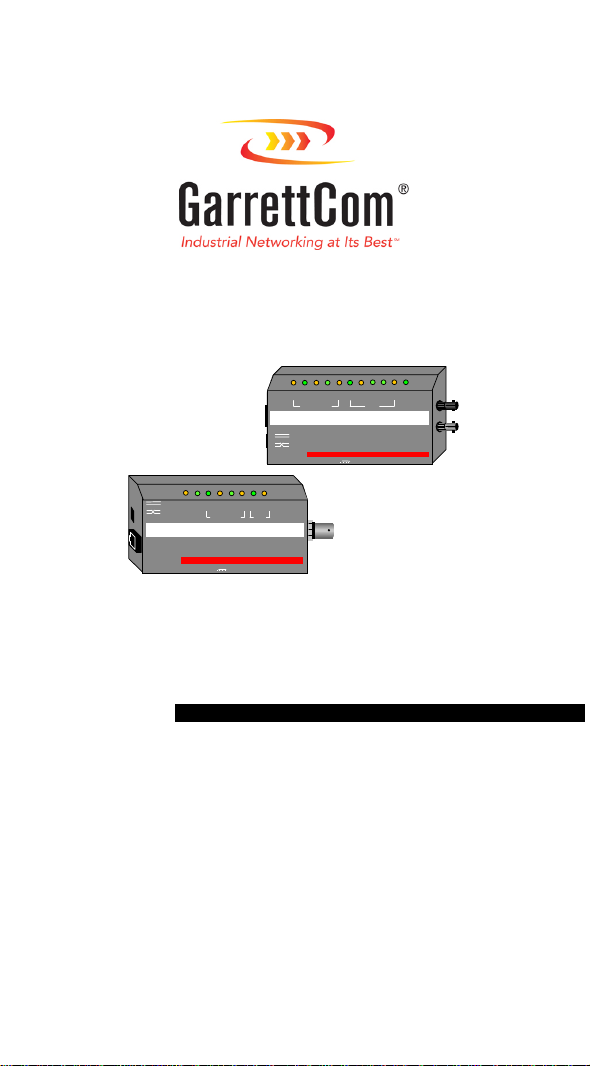
Magnum 10Mb/s Media Converters
Pwr
Jab
12 VDC 1 AM P
Li nkTXColRXColRXPol
FIBERTW ISTED PAIR
UP LINK
GARRETT
TW ISTED PAIR
M agnum TB15 Media Converter
COAX
12 VDC 1 AM P
Li nk
Pwr
Jab
Li nk
Jab
M agnum TF15 Media Converter
UP LINK
GARRETT
ColRXColRXPol
Half- and full-duplex fiber models
Installation and User Guide
GARRETT
Page 2

Magnum 10Mb Media Converters Installation a nd User Guide (07/98)
Magnum 10Mb/s Media Converters
Installation and User Guide
Part#: 84-00001 (R07/98)
Trademarks
UL is a registered trademark of Underwriters Laboratories
Ethernet is a trademark of Xerox Co rporation
Velcro is a trademark of Velcro U.S. A.
GARRETT
Page 3

Magnum 10Mb Media Converters Installation a nd User Guide (07/98)
Important:
Attempted service by unauthorized personnel shall render any and all
warranties null and void. If problems are experienced with a Magnum Media
Converter, consult Section 5, Troubleshooting, of this User Guide.
1998 Garrett Communications, Inc.
Magnum Media Converters contain no user serviceable parts.
GARRETT
Page 4

Magnum 10Mb Media Converter s Installation and User Guide (07/98)
Please use the mailing address, email, phone and fax numbers listed below:
GarrettCom, Inc.
47823 Westinghouse Drive
Fremont, CA 94539
Phone (510) 438-9071
Fax (510) 438-9072
email: support@garrettcom.com
GARRETT
Page 5

Magnum 10Mb Media Converters Installation a nd User Guide (07/98)
FCC STATEMENT
FEDERAL COMMUNICATIONS COMMISSION
RADIO FREQUENCY INTERFERENCE STATEMENTS
This equipment generates, uses, and can radiate radio frequency energy and if not installed and used
properly, that is, in strict accordance with the communication. It has been tested and found to
comply with the limits for a Class A computing device in accordance with the specifications in
Subpart J of Part 15 of FCC rules, which are designed to provide reasonable protection against such
interferen ce when the eq uipment is operated in a com mercial environment. O peration of this
equipment in a residential area is likely to cause interference, in which case the user at his own
expense will be required to take whatever measures may be necessary to correct the interference.
GARRETT
Page 6

Magnum 10Mb Media Converters Installation a nd User Guide (07/98)
TABLE OF CONTENTS Page
1.0 SPECIFICATIONS .................................................................................................1
1.1. Technical Specifications................................................................................1
2.0 INTRODUCTION...................................................................................................7
2.1 Inspecting the Package and Product ...............................................................7
2.2 Product Description ***..................................................................................9
2.3 Features and Benefits ***.............................................................................16
2.4 Applications, TB15, BF15, and TP/fiber Link Pass-through ***.................18
2.5 Full-duplex twisted-pair/fiber applications *** ............................................21
3.0 INSTALLATION..................................................................................................22
3.1 Locating the Media Converter Unit..............................................................22
3.2 Calculating Overall Segment Distances........................................................23
3.3 Connecting Ethernet Media..........................................................................27
3.3.1 Connecting Twisted Pair (RJ-45, standard and Link Pass-through).27
3.3.2 Connecting ThinNet 10BASE2 (BNC) ...........................................29
3.3.3 Connecting Fiber (ST & SC, mm & sgl.mode, Full/half duplex)*** 29
GARRETT
Page 7

Magnum 10Mb Media Converters Installation a nd User Guide (07/98)
TABLE OF CONTENTS (CONTINUED) Page
4.0 OPERATION ........................................................................................................32
4.1 Power Requirements, Power Supply Types..................................................32
4.2 Front Panel LEDs - Magnum TB15............................................................33
4.3 Front Panel LEDs - Magnum BF15…………………………………………34
4. 4 Front Panel LEDs - Magnum TF15, TF15 s, TF15SC, TF15-hdx *** …35
4.5 Up-Link (Cross-over) Switch........................................................................36
5.0 TROUBLESHOOTING.........................................................................................37
5.1 Before Calling for Assistance.......................................................................38
5.2 When Calling for Assistance.........................................................................40
5.3 Return Material Authorization (RMA) Procedure .......................................41
5.4 Shipping and Packaging Information............................................................43
Garrett Communications reserves the right to change specifications, performance characteristics
and/or model offerings without notice.
*** Changes made in 1998. Fiber SC-type connector models, full- and half-duplex transparent
operation fiber models, and Link Pass-through fiber models added.
GARRETT
Page 8

Magnum 10Mb Media Converters Installation a nd User Guide (07/98)
1.0 SPECIFICATIONS
1.1.
Technical Specs - fiber full/half Models: TF15, TF15s, TF15SC, TF15LP
and, standard “Collision-indicating” models: TB15, BF15, TF15-hdx
Performance:
Data Rate: 10 Mbps (IEEE 802.3)
Network Standards:
Ethernet V1.0/2.0 IEEE 802.3: 10BASE2, 10BASE-T, FOIRL,
10BASE-FL
(Magnum Media Converters are physical layer standard Ethernet products,
and operate independently of all software.)
Number of Media Converters in series:
Experience shows that up to three units can be used in series between repeaters.
For 4 or more in series, noise build-up will typically preclude proper operation.
GARRETT
1
Page 9

Magnum 10Mb Media Converters Installation a nd User Guide (07/98)
Maximum Standard Ethernet Segment Lengths:
10BASE-T (unshielded twisted pair): 100 m (328 ft)
10BASE2 ThinNet (BNC): 185 m (607 ft)
FOIRL Fiber optic: 1.0 km (3,281 ft)
10BASE-FL Fiber optic : 2.0 km (6,562 ft)
10BASE-FL Single Mode Fiber optic: 10.0 km (32,810ft)
(for single-mode, full-duplex operation for distances over approx. 4Km.)
Note: Magnum Media Converters
segments. See Section 3.2 of this manual for media lengths and segment
distance calculations.
Operating Environment:
DO NOT
support full length Ethernet
Ambient Temperature: 32ºF to 122ºF (0ºC to 50ºC)
Storage Temperature: -20ºC to 60ºC
Ambient Relative Humidity: 10% to 95% (non-condensing)
GARRETT
2
Page 10

Magnum 10Mb Media Converters Installation a nd User Guide (07/98)
Power Supply (Ext ernal):
Power Input: 95 - 125 vac at 60 Hz for U.S. and Canadian models,
200 - 250 vac at 50 Hz for international models which have
IEC power cable connector.
Power Consumption: 6 watts max. for the Media Converter
Connectors:
RJ-45 Port: Modular 8-Pin female, with “cross-over” up-link switch
BNC Port: Standard BNC connector, RG-58 ThinNet
Fiber Port: Fiber optic (standard ST & SC types), 10BASE-FL
Fiber, Full- and half-duplex:
Fiber models capable of full- or half-duplex transparent operation have a tag on
the bottom marked “FULL/HALF DUPLEX”, and do not indicate collisions.
GARRETT
3
Page 11

Magnum 10Mb Media Converters Installation a nd User Guide (07/98)
Packaging:
Enclosure: High strength sheet metal.
Dimensions:
TB15:
2.5 in x 3.75 in x 0.75 in (6.35 cm x 9.53 cm x 1.9 cm)
BF15:
2.5 in x 3.75 in x 0.75 in (6.35 cm x 9.53 cm x 1.9 cm)
TF15, TF15s, TF15SC, TF15LP, TF15-hdx:
2.5 in x 3.9 in x 0.75 in (6.35 cm x 9.90 cm x 1.9 cm)
Power Supply: 2.0 in x 2.0 in x 1.5 in (5.1 cm x 5.1 cm x 3.8 cm)
Weight:
All Models:
6.9 oz. (197g); power supply 10 oz (285g)
GARRETT
4
Page 12

Magnum 10Mb Media Converters Installation a nd User Guide (07/98)
Media Converter LED Indicators:
LED TB15
PWR unit unit unit Indicates unit is receiving DC power.
Link TP Fiber TP, Fiber Steady ON when proper link is
RX TP, BNC BNC, Fiber TP, Fiber Indicates port is receiving packets.
TX n.a. BNC, Fiber Fiber Indicates port is transmitting packets
POL TP n.a. TP Indicates the unit has detected a TP receive
COL* TP, BNC BNC, Fiber TP, Fiber Indicates unit is simultaneously transmitting
JAB* unit BNC TP, Fiber Indicates jabber (illegal packet length fault)
BF15 TF15,TF15s, SC, LP,-hdx Description
established at both ends of the segment.
wire-pair signal inversion (polarity).
and receiving data from the cables.
condition. Segment is partitioned when lit.
NOTE:
*COL and JAB LEDs (when present) are disabled for “FULL/HALF DUPLEX” units,
which are transparent to the Collision and Jabber conditions and do not indicate them.
GARRETT
5
Page 13

Magnum 10Mb Media Converters Installation a nd User Guide (07/98)
Agency Approvals:
115v 60 Hz Power Supply is UL Listed (UL 1310), CSA Certified
230v 50 Hz Power Supply is same, also TUV and GS approved
Emissions: Meets FCC Part 15 Class A, cUL
Warranty:
GARRETT
Three years, return to factory Made in USA
6
Page 14

Magnum 10Mb Media Converters Installation a nd User Guide (07/98)
2.0 INTRODUCTION
This section describes the TF15, TF15s, TF15SC, TF15LP, TF15-hdx, TB15
and BF15 including appearance, features and typical applications.
2.1 Inspecting the Package and Product
Examine the shipping container for obvious damage prior to installing this
product; notify the carrier of any damage which you believe occurred during shipment or
delivery. Inspect the contents of this package for any signs of damage and ensure that the
items listed below are included.
GARRETT
7
Page 15

Magnum 10Mb Media Converters Installation a nd User Guide (07/98)
This package should contain:
1 Magnum Media Converter Unit
1 External Power Supply, either 115 vac 60 Hz or 230 vac 50 Hz
1Velcro
1User Guide
Remove the Magnum Media Converter from the shipping container. Be sure to
keep the shipping container should you need to ship the unit at a later date.
In the event there are items missing or damaged contact your supplier. If you
need to return the unit use the original shipping container. Refer to Section 5,
Troubleshooting, for specific return procedures.
Tape section, approximately 3 inches in length
GARRETT
8
Page 16

Magnum 10Mb Media Converters Installation a nd User Guide (07/98)
2.2
pre-existing Ethernet cabling configuration as network requirements change. They offer
a graceful way to convert and transmit data among twisted pair, thin coaxial and fiber
network cabling environments. A variety of twisted-pair-to-fiber models provide for
multi-mode or single-mode, full- or half-duplex, ST or SC connectors, and normal or
Link Pass-through operation. Magnum Media Converters cost significantly less than full
repeaters and can be used whenever media distance limitations will not be exceeded in
the new environment. All units are compatible with Ethernet V 1.0 / 2.0 specifications
and comply with IEEE 802.3 standards.
Product Description
Magnum 10Mb Media Converters offer a compact, cost-effective way to adapt a
GARRETT
9
Page 17

Magnum 10Mb Media Converters Installation a nd User Guide (07/98)
Magnum Media Converters are designed for quick and easy installation even in
very tight spaces. Media cables are easily attached to the corresponding Media
Converter. Because of their compact size, Magnum Media Converters can be Velcro ®mounted on an office wall or the side of a desk or cabinet. The external power supply
plugs into a nearby AC wall socket or power strip. Each converter features a full set of
LEDs that convey essential diagnostic and status information. See Section 4.1, LED
Indicators, for specific LED function information.
Magnum Media Converters are designed to provide low-temperature operation
over an extended period to make them some of the most reliable in the industry. Their
high-strength fabricated metal packaging shields against Radio Frequency Interference
(RFI) and Electromagnetic Interference (EMI).
GARRETT
10
Page 18

Magnum 10Mb Media Converters Installation a nd User Guide (07/98)
Magnum Media Converters are specifically designed to convert data signaling
to allow transmission between two different Ethernet cabling types, allowing migration to
a new media type while preserving segments of the pre-existing wiring structure.
All of the Magnum Media Converters comply with the IEEE 802.3 10BASE-T
specification for 10 Mb/sec traffic via shielded (STP) or unshielded twisted pair (UTP)
segments. The Media Converters feature an up-link or cross-over switch to eliminate the
need for a special cross-over cable when connecting to a hub or concentrator.
Note: experience shows that the maximum number of 10Mb Media Converters
that can be used in series is three. The cumulative noise from 4 or more units together
causes packet alig nment errors.
GARRETT
11
Page 19

Magnum 10Mb Media Converters Installation a nd User Guide (07/98)
The TB15 is equipped with one BNC and one RJ-45 port. The BNC connector
complies with IEEE 802.3 10BASE2 specifications for ThinNet segments.
Twisted Pair
(10BASE-T)
UP LINK
Magnum TB 15 Media Converter
GARRETT
TWISTED PAIR
12 VDC 1 AMP
Link
Pwr
Jab
ColRXColRXPol
COAX
ThinNet-BNC
The TB15 integrates 10BASE-T and 10BASE2 Ethernet networks.
GARRETT
12
(10BASE-2)
Page 20

Magnum 10Mb Media Converters Installation a nd User Guide (07/98)
The Magnum BF15 is equipped with one BNC and one Fiber-ST connector for
connection to IEEE FOIRL or 10BASE-FL compliant networks.
ThinNet-BNC
(10BASE-2)
The BF15 integrates Thi nNet and Fiber Etherne t networks.
GARRETT
Jab
Link
Jab
Magnum BF 15 Media Converter
GARRETT
12 VDC 1 AMP
LinkTXColRXColRXPol
FIBERTWISTED PAIR
13
Fiber Optic - ST Connector
(10BASE-FL and FO IR L)
Pwr
TX RX
Page 21

Magnum 10Mb Media Converters Installation a nd User Guide (07/98)
The Magnum TF15 (multi-mode ST), TF15s (single-mode ST), TF15LP (Link
Pass-through) and TF15-hdx (Half-duplex multi-mode ST) are equipped with one fiberST and one twisted pair RJ-45 connector for connection to IEEE FOIRL or 10BASE-FL
compliant networks. All of these* (except the TF15-hdx ) operate transparently at full- or
half-duplex mode for devices at both ends.
Twisted Pair
(10BASE-T)
Link
Jab
Magnum TF 15 Media Converter
UP LINK
GARRETT
12 VDC 1 AMP
The TF15 (ST type) integrates 10BASE-T and Fiber Ethernet networks.
*
Non-Collision-indicating models are tagged “FULL/HALF DUPLEX” on the bottom.
Pwr
Jab
LinkTXColRXColRXPol
FIBERTWISTED PAIR
(10BASE-FL and FOIRL)
TX R X
GARRETT
14
Fiber Optic - ST Connector
Page 22

Magnum 10Mb Media Converters Installation a nd User Guide (07/98)
The Magnum TF15SC* has one fiber-SC (multi-mode) and one RJ-45
connector.
Twisted Pair
(10BASE-T)
Link
Jab
Magnum TF 15
UP LINK
GARRETT
Media Converter
12 VDC 1 AMP
The TF15SC (SC type) integrates 10BASE-T and Fiber Ethernet networks.
*
Non-Collision-indicating models are tagged “FULL/HALF DUPLEX” on the bottom.
Pwr
Jab
LinkTXColRXColRXPol
FIBERTWISTED PAIR
(10BASE-FL and FOIRL)
TX RX
GARRETT
15
Fiber Optic - SC Connector
Page 23

Magnum 10Mb Media Converters Installation a nd User Guide (07/98)
2.3 Features and Benefits
Reduces Network Costs
!!!!
Magnum Media Converters offer the ideal solution to quickly and
inexpensively connect Twisted Pair with Fiber or ThinNet media within
an expanding Ethernet network where full repeaters are not required.
No added Repeater Hop Count
!!!!
Media Converters do not add signal timing delays associated with full
repeaters, and can be installed without increasing the repeater hop count
of an existing network.
Fiber / twisted-pair models f o r all fiber modes and media types
!!!!
A variety of twisted-pair-to-fiber models provide for multi-mode or singlemode fiber, full- or half-duplex mode, ST or SC connectors, and normal or
Link Pass-through operation.
GARRETT
16
Page 24

Magnum 10Mb Media Converters Installation a nd User Guide (07/98)
Small, Compact, Lightweight Design
!!!!
Featuring a compact and lightweight metal case with an external power
supply, Magnum Media Converters can be conveniently installed in
minimal space on table-tops or wall-mounted.
Full Complement of LEDs.
!!!!
Each Media Converter model is equipped with a full complement of LEDs
to provide network traffic status and basic diagnostic information without
additional network diagnostic equipment.
Highly Reliable and Dependable
!!!!
Magnum Media Converters are based on a robust design and are packaged
in a metal enclosures to ensure high reliability and durability.
GARRETT
17
Page 25

Magnum 10Mb Media Converters Installation a nd User Guide (07/98)
2.4
media types to coexist inexpensively within the same network by allowing data to be
transmitted and received between different media types.
networking equipment is being installed and connecting to new / existing fiber or BNC
Ethernet cabling is required. Alternatively, two twisted-pair-to-fiber models (typically
TF15 for multi-mode and TF15s for single-mode) are convenient for inserting a fiber
segment into a twisted pair environment in order to connect to a remote workstation or
workgroup via fiber cabling, without increasing the repeater hop count.
networks, where the LINK indication passes-through from the fiber side to the TP side.
Applications
The primary function of a Magnum Media Converter is to permit two different
Magnum Media Converters are typically used where new 10BASE-T
The TF15LP, with the Link Pass-through feature, is often desired for managed
GARRETT
18
Page 26
Magnum 10Mb Media Converters Installation a nd User Guide (07/98)
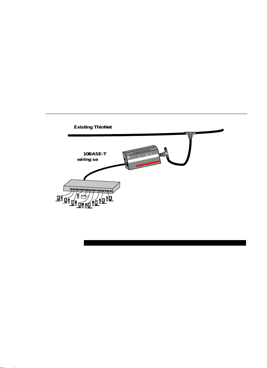
Existing ThinNet (10BASE2) backbone
Col
RX
Col
RX
Pol
Link
Pwr
Jab
M agn um TB
TWISTED PAIR
Media C onverter
15
12 VDC 1 AM P
COAX
10BASE-T
wiring segment
1 2 3 4
5 6 7 8 9 10 11 12 13 14 15 16 17 18 19 20 21 22 23 24
UP LINK
GARRETT
Magnum TB15 provides connectivity for 10BASE-T
devices though an existing BNC network tap.
GARRETT
19
Page 27

Magnum 10Mb Media Converters Installation a nd User Guide (07/98)
g
Central network
with 10Mb/s
fiber backbone
Pwr
Jab
Link
TX
Col
RX
Col
RX
Pol
Link
Jab
10BASE-T
wirin
segment
TWISTED PAIR
Magnum TF
GARRETT
FIBER
Media Converter
15
Magnum TF15 provides connectivity between a
fiber network and 10BASE-T network devices.
GARRETT
20
Page 28

Magnum 10Mb Media Converters Installation a nd User Guide (07/98)
Magnum Media Converters have an external power supply, enabling them to be
used to convert signals among media that does not have a power source as part of the
cabling system, such as twisted pair, BNC and Fiber. (AUI ports can supply power).
2.5 Full / hal f-duplex applications.
Of the various 10Mb media types, only the twisted-pair to fiber combination is
capable of full-duplex (i.e., simultaneously transmitting and receiving on the same cable
segment) operation. Full-duplex is rarely required at 10Mb, but might occasionally be
desired to connect a 10Mb RJ-45 switch port over a fiber link to a full-duplex RJ-45 NIC
in a remote server, or to connect to another full-duplex 10Mb RJ-45 switch port.
The various TF15 units tagged FULL/HALF DUPLEX operate transparently to
the simultaneous TX / RX condition, and do not indicate Collisions or Jabber even if
they are present. They are suitable for all normal half- and full-duplex applications.
GARRETT
21
Page 29

Magnum 10Mb Media Converters Installation a nd User Guide (07/98)
3.0 INSTALLATION
This section describes the installation of the Magnum Media Converters,
including location, segment distance calculation and media connection.
3.1 Locating the Medi a Convert er Unit
The compact and lightweight design of the Magnum Media Converter allows it
to be easily installed in almost any location. A Velcro strip is included for mounting the
unit on a vertical su rface such as a wall
or cabinet, or for securing the unit on a
table-top or shelf. Installation location is
dependent upon the physical layout of
the Ethernet network. Make sure the
unit is installed in a location that will be
easily accessible to an AC power outlet
Secure attachment of mounting
clips for wall mounting
GARRETT
22
Page 30

Magnum 10Mb Media Converters Installation a nd User Guide (07/98)
or power strip, and where convection cooling is not inhibited.
For rack-mounting of media converters, the Magnum MC-TRAY is available.
GARRETT
23
Page 31

Magnum 10Mb Media Converters Installation a nd User Guide (07/98)
Important Note:
segment lengths on each side of the Magnum Media Converter. It i s
recommended that IEEE 802.3 specifications for overall maximum segment
distances be adhered to in order to maintain optimum network performance.
(See Technical Specs, Maximum Standard Ethernet Segment Distan ces,
Section 1.1 of this manual.)
3.2 Calculating Overall Segment Distance
When installing the Magnum Media Converter, it is important to consider the
combined overall segment length of both of the attached media types. The overall
segment length is calculated by adding together the segment lengths on both sides of the
Magnum Media Converters. Segment length on each side of the Media Converter is
Special consideration must be given to maximum
GARRETT
24
Page 32

Magnum 10Mb Media Converters Installation a nd User Guide (07/98)
measured as a percentage of the maximum allowable standard media distance for the
given media type. The percentages, when added together, must not exceed 100%.
Media Distanc e * Formula for Magnum Me dia Converters:
X% + Y% < 100%
Where X = The segment distance on one side of the Magnum
Media Converter divided by the Standard Maximum
Media Distance for that media type, x 100%
Where Y = The segment length on the other side of the Magnum
Media Converter divided by the Standard Maximum
Media Distance for that media cabling type, x 100%
Notes:
1) Media distance calculation is the same for both half and full duplex media converters.
2) Single-mode fiber distances more than approximately 4Km will exceed the collision
GARRETT
25
Page 33

Magnum 10Mb Media Converters Installation a nd User Guide (07/98)
domain limits, and should be operated at either full-duplex or with light traffic.
GARRETT
26
Page 34

Magnum 10Mb Media Converters Installation a nd User Guide (07/98)
Distance Calculation Example:
A
Segment Y
55m (165 ft)
Twisted Pair
(10BASE-T)
TWISTED PAIR
ColRXColRXPol
COAX
Link
Pwr
Jab
UP LINK
Magnum TB 15 Media Converter
GARRETT
12 VDC 1 AMP
Segment X
72m (216 ft)
ThinNet-BNC
(10BASE-2)
Connectivity between ThinNet and TP Ethernet Media.
In the figure shown above, the length of Segment X is 72m (216 ft). This is
39% of the maximum allowable distance for 10BASE2 media (185 m) [72/185 x 100% =
39%]. The length of Segment Y is 55m (165 ft). This is 55% of the maximum allowable
GARRETT
27
Page 35

Magnum 10Mb Media Converters Installation a nd User Guide (07/98)
distance for UTP 10BASE-T media (100 m) [55/100 x 100% = 55%]. The total of the
two percentages (39% + 55%) is 94%, which is allowable.
Note 1
:
Where more than one media converter is used in one
segment run, the percentages for all of the cabling lengths in the run
must be added together and must not exceed 100%.
Note 2
:
If the total segment distance calculation result is greater than
100%, consider using a Magnum Repeater so that each cable type can
be 100% of its maximum allowed length.
Note 3
: The maximum number of 10Mb Media Converters that can
be used in series is three. The cumulative noise from four or more
units together causes packet alignment errors.
GARRETT
28
Page 36

Magnum 10Mb Media Converters Installation a nd User Guide (07/98)
3.3 Connecting Ethernet Media
Connecting Ethernet media to the Magnum Media Converter is very simple and
straightforward. Using a properly terminated media segment, simply attach the cable end
to the appropriate connector.
See Sections 4.2 and 4.3 for a description of the LEDs of the media converter
models.
3.3.1 Connecting Twi sted Pair (RJ-45, standar d and Link Pass-through models)
The following procedure describes how to connect a 10BASE-T twisted pair
segment to the RJ-45 port on the Magnum Media Converters. The procedure is the same
for both unshielded and shielded twisted pair segments.
GARRETT
29
Page 37

Magnum 10Mb Media Converters Installation a nd User Guide (07/98)
1. Using standard 10BASE-T media, insert either end of the cable with an RJ-45
plug into the RJ-45 connector of the Magnum Media Converter.
2. Connect the other end of the cable to the corresponding device.
3. Use the LINK LED (non-Link pass-through models) to ensure proper
connectivity by noting that the LED will be illuminated when the units are
powered and proper connections established. If the LINK LED is not illuminated,
change the setting of the up-link switch (See Section 4.4 for up-link switch
information.) If this does not help, ensure that the cable is connected properly at
both ends and is not defective.
4. For the TF15LP model with the Link-Pass-through feature, The two LINK LEDs
operate together, and either both LEDs are lit or neither is lit. Both of the
attached cables must be operable for LINK to be indicated. Absence of LINK
does not point to the problem cable segment, and the fault may be in either.
GARRETT
30
Page 38

Magnum 10Mb Media Converters Installation a nd User Guide (07/98)
3.3.2 Connecting ThinNet 10BASE2
Connect the ThinNet coax cable to the BNC connector on the TB15 Media
Converter in the same manner as is done for any standard BNC connection. Be sure that
the BNC segment is properly terminated using a standard “T” connector and terminator.
3.3.3 Connecting Fiber Optic multi-mode, si ngle mode
The following procedure applies to 10BASE-FL multi-mode and single mode
applications using the TF15, TF15s, TF15SC, TF15LP and TF15-hdx Media Converters.
All have ST-type fiber connectors, except the TF15SC which has SC-type connectors.
The TF15s single-mode differs from the other fiber media converters in terms of
the maximum distance allowed. The others are used for a multi-mode fiber segment
lengths of up to 2km. The TF15s is used for single-mode fiber segments of up to 10km
in length. The following table is provided for general information:
GARRETT
31
Page 39

Magnum 10Mb Media Converters Installation a nd User Guide (07/98)
Fiber Cable Type cable diameter * Max. length Wavelength
Multi-mode fiber 50/125, 62.5/125, 2km 850 nm
80/125, 100/140 ** (see next page)
Single-mode fiber 2/15 - 8/60 10km 1300 nm
* xx/yy are the diameters of the core and the core plus cladding respectively
** The values shown are typical values
Procedure for connecting multi-mode and single-mode fiber cables:
1. Before connecting the fiber cable, remove the protective dust caps from the tips of
the connectors on the media converter. Save these d ust caps for future use.
2. Wipe clean the ends of the dual connectors with a soft cloth or lint-free lens tissue
dampened in alcohol. Make certain the connectors are clean before connecting.
GARRETT
32
Page 40

Magnum 10Mb Media Converters Installation a nd User Guide (07/98)
Note: One strand of the duplex fiber optic cable is coded using color
bands at regular intervals; you must use the color-coded strand on
the associated ports at each end of the fiber optic segment.
3. Connect the Transmit (TX) port (light colored post) on the Magnum Media
Converter to the Receive (RX) port of the remote device. Begin with the colorcoded strand of the cable for this first TX-to-RX connection.
4. Connect the Receive (RX) port (dark-colored post) on the product to the Transmit
(TX) port of the remote device. Use the non-color coded fiber strand for this.
5. The LINK LED corresponding to the fiber port on the front of the product will
illuminate (for standard non-Link-Pass-through models) when a proper
connection has been established at both ends (and when power is ON in the units
at each end). If LINK is not lit after cable connection, the normal cause is
improper cable polarity. Swap the fiber cables on the product connector to
remedy this situation.
6. For the Link Pass-through model, connection is the same except that the LINK
indication will not be present unless LINK is made for the cables on both sides.
GARRETT
33
Page 41

Magnum 10Mb Media Converters Installation a nd User Guide (07/98)
4.0 OPERATION
This section describes the operation of the Magnum Media Converters
including power supply requirements, up-link switch functionality, and a description of
all LEDs.
4.1 Power Requirements, Power Supply Types
Magnum Media Converters require 6 watts of power and are designed to be
used with an external power supply.
two types; one version (U.S. and Canadian models) for AC input power of 115 vac 60
Hz, and one international version for 230 vac 50 Hz. The 115 vac version has a small
transformer integral with a convenience power outlet plug. The 230 vac version has a
small transformer integral with an IEC-type power plug for a user-supplied AC power
cord with a convenience power outlet plug. Both types include a lightweight DC power
cord to the appli cable power jack on the Medi a Converter unit.
The external power supply unit supplied is one of
GARRETT
34
Page 42

Magnum 10Mb Media Converters Installation a nd User Guide (07/98)
4.2 Front Pane l LEDs - - Magnum TB15
LED Description
PWR
LINK
RX
POL
JAB
COL
Illuminates GREEN to indicate the unit is receiving DC power.
(TP) Illuminates GREEN, to indicate proper connectivity on the
10BASE-T network segment. LINK will turn off in the event
connectivity is lost between the ends of the twisted pair segment
or a loss of power occurs in the unit or remote device.
(per port) Illuminates GREEN to indicate data is being received.
(TP) Illuminates AMBER to indicate inverse polarity detected.
Illuminates AMBER to indicate jabber (illegal packet length).
(per port) Illuminates AMBER to indicate a collision on the
segment.
GARRETT
35
Page 43

Magnum 10Mb Media Converters Installation a nd User Guide (07/98)
4.3 Front Pane l LEDs - - Magnum BF15
LED Description
PWR
LINK
RX
TX
JAB
COL
Illuminates GREEN to indicate the unit is receiving DC power.
(TP) Illuminates GREEN, to indicate proper connectivity on the
10BASE-T network segment. LINK will turn off in the event
connectivity is lost between the ends of the twisted pair segment
or a loss of power occurs in the unit or remote device.
(per port) Illuminates GREEN to indicate data is being received.
Illuminates GREEN to indicate attached host is transmitting data
over the cable.
Illuminates AMBER to indicate jabber (illegal packet length).
(per port) Illuminates AMBER to indicate a collision on the
segment.
GARRETT
36
Page 44

Magnum 10Mb Media Converters Installation a nd User Guide (07/98)
4.4 Front Panel LEDs - Magnum TF15, TF15s, TF15SC, TP15LP, TF15-hdx
LED Description
PWR
LINK
RX
TX
POL
JAB*
COL*
* Not applicable to FULL/HALF DUPLEX models, including Link-Pass-through.
Illuminates GREEN to indicate the unit is receiving DC power.
(per port) Illuminates to indicate proper connectivity on each cable
segment (non-Link Pass-through models). LINK will turn off in
the event connectivity is lost between the ends of each cable
segment or a loss of power occurs in the unit or in the attached
device. For Link Pass-through models, see Section 3.3.3 #6.
(per port) Illuminates GREEN to indicate data is being received.
(Fiber) Illuminates GREEN to indicate data is being transmitted
(TP) Illuminates AMBER to indicate inverse polarity detected.
(per port) When present, illuminates to indicate half-duplex Jabber
(illegal packet length) condition. (Inoperable or not present on
models with the FULL/HALF DUPLEX tag on the unit’s bottom).
(per port) When present, illuminates to indicate a half-duplex
Collision on the segment. (Inoperable or not present on models
with the FULL/HALF DUPLEX tag on the bottom of the unit).
GARRETT
37
Page 45

Magnum 10Mb Media Converters Installation a nd User Guide (07/98)
4.5 Up-Link (Cross-over) Switch
Magnum Media Converters are equipped with an up-link slide switch on the
RJ-45 port to accommodate repeater-to-converter and switch-to-converter connections
without a special cross-over cable.
4.5.1 Up-Link (Cross-over) Switch
When set to the UP position (=), the
Magnum Media Converter is wired for normal
twisted-pair connection to a user node device. When
ser device (=)
up-link (X)
End view, TP port
Up-link
Switch
set to the DOWN position (X), the Media Converter
is wired with cross-over functionality for direct up-link to a network hub or concentrator.
Switch ports may be of either polarity, and this feature is most convenient with switches..
GARRETT
38
Page 46

Magnum 10Mb Media Converters Installation a nd User Guide (07/98)
5.0 TROUBLESHOOTING
All Magnum Ethernet products are designed to provide reliability and
consistently high performance in all network environments. The installation of Magnum
Media Converters is a simple procedure (see Section 3.0, INSTALLATION); operation
is very simple and is described in Section 4.0, OPERATION.
Should problems develop during installation or operation, this section should
help to locate, identify and correct such problems. Please follow the suggestions listed
below prior to contacting your supplier. However, if you are unsure of any procedure
described in this section, or if the Magnum Media Converter is not operating as
expected, do not attempt to repair or alter the unit. Contact your supplier (or if unknown,
contact Garrett Communications) for assistance.
GARRETT
39
Page 47

Magnum 10Mb Media Converters Installation a nd User Guide (07/98)
5.1 Before Calling for Assistance
1. If difficulty is encountered when installing or operating the Magnum Media
Converter, refer back to Section 3.0, Installation and Section 4.0, Operation. Check to
make sure that the various other components of the network are operable.
2. Check the cables and connectors to ensure that they have been properly
connected, and the cables/wires have not been crimped or in some way impaired during
installation. (About 90% of network downtime can be attributed to wiring and connector
problems.)
3. Make sure that the external DC power supply is properly attached to the
unit, that it is of the proper type, and that it is plugged into a functioning electrical outlet.
Use the PWR LEDs to verify the unit is receiving proper power.
GARRETT
40
Page 48

Magnum 10Mb Media Converters Installation a nd User Guide (07/98)
4. If the problem is isolated to a network device other than the Magnum
Media Converter, it is recommended that the problem device be replaced with a known
good device. Verify whether or not the problem is corrected. If not, go to Step 5 below.
If the problem is corrected, the Magnum Media Converter and i ts associated cables are
functioning properly.
5. If the problem continues after completing Step 4 above, contact your
supplier of the Magnum Media Converter (or if unknown, contact Garrett
Communications) by fax, phone or email for assistance.
GARRETT
41
Page 49

Magnum 10Mb Media Converters Installation a nd User Guide (07/98)
5.2 When Calling for Assistance
Please be prepared to provide the followin g i nformation.
1. A complete description of the problem, including the following points:
a. The nature and duration of the problem;
b. Situations when the problem occurs;
c. The components involved in the problem;
d. Any particular application that, when used, appears to create the problem;
2. An accurate list of Garrett Communications product model(s) involved, with
serial number(s). Include the date(s) that you purchased the products from
your supplier.
3. It is useful to include other network equipment models and related hardware,
including personal computers, workstations, terminals and printers; plus, the
various network media types being used.
4. A record of changes that have been made to your network configuration prior
to the occurrence of the problem. Any changes to system administrat ion
procedures should all be noted in this record.
GARRETT
42
Page 50

Magnum 10Mb Media Converters Installation a nd User Guide (07/98)
5.3 Return Material Authorization (RMA) Pr oc e dure
All returns for repair must be accompanied by a Return Material Authorization
(RMA) number. To obtain an RMA number, contact Garrett Communications Customer
Support at (510) 438-9071 (office hours: 8AM - 5PM Pacific Standard Time) or send
email to
when calling:
support@garrettcom.com
Name and phone number of your contact person.
Name of your company / institution
Your shipping address
Product name
Serial Number (or Invoice Number)
Packing List Number (or Sales Order Number)
Date of installation
Failure symptoms, including a full description of the problem.
. Please have the following information available
GARRETT
43
Page 51

Magnum 10Mb Media Converters Installation a nd User Guide (07/98)
Garrett Communications will carefully test and evaluate all returned products,
will repair products that are under warranty at no charge, and will return the warrantyrepaired units to the sender with shipping charges prepaid (see Warranty Information,
Appendix A, for complete details). However, if the problem or condition causing the
return cannot be duplicated by Garrett Communications, the unit will be returned as:
No Problem Found.
Garrett Communications, Inc. reserves the right to charge for the testing of
non-defective units under warranty. Testing and repair of product that is not under
warranty will result in a customer (user) charge.
GARRETT
44
Page 52

Magnum 10Mb Media Converters Installation a nd User Guide (07/98)
5.4 Shipping and Packaging Information
Should you need to ship the unit back to Garrett Communications, please
follow these instructions:
1. Package the unit carefully. It is recommended that you use t he original
container if available. Units should be wrapped in a "bubble-wrap" plastic
sheet or bag for shipping protection. ( You may retain all connectors and this
Installation Guide.)
CAUTION
Do not pack the unit in Styrofoam "popcorn" type packing material . This
material may cause electro-static shock damage to the unit.
GARRETT
45
Page 53

Magnum 10Mb Media Converter s Installation and User Guide (07/98)
2. Clearly mark the Return Material Authorization (RMA) number on the
outside of the shipping container.
3. Garrett Communications is not responsible for your return shipping charges.
4. Ship the package to:
GarrettCom, Inc.
47823 Westinghouse Drive
Fremont, CA 94539
Attn.: Customer Service
GARRETT
46
 Loading...