

Page 1
Magnum Workgroup Hubs
“Ten Series”
Models 1008, 1016 and 1024
Installation and User Guide
www GarrettCom com
..
Page 2

Magnum 1000 Workgroup Hubs Installation and User Guide (04/02)
Magnum 1008, 1016 and 1024
and optional 48VDC, 24VDC &125VDC-powered models
Workgroup Hubs
Installation and User Guide
Part #: 84-00030 Rev 04/02
Trademarks
Ethernet is a trademark of Xerox Corporation
NEBS is a trademark of Telcordia Technologies
UL is a registered trademark of Underwriters Laboratories
GarrettCom, Magnum and Personal Switch are trademarks and Personal Hub is a
registered trademark of GarrettCom, Inc.
Important: The Magnum 1000 series workgroup hub family contains no user
serviceable parts. Attempted service by unauthorized personnel shall render
all warranties null and void. If problems are experienced with Magnum 1000
series workgroup hub products, consult Section 5, Troubleshooting, of this
User Guide.
Copyright 2002 GarrettCom, Inc. All rights reserved. No part
of this publication may be reproduced without prior written permission from
GarrettCom, Inc.
Printed in the United States of America.
www GarrettCom com
..
i
Page 3

Magnum 1000 Workgroup Hubs Installation and User Guide (04/02)
Contacting GarrettCom, Inc
Please use the mailing address, phone and fax numbers and email address listed below:
GarrettCom, Inc.
47823 Westinghouse Drive
Fremont, CA 94539
Phone (510) 438-9071
Fax (510) 438-9072
Website: http://www.GarrettCom.com
email support@garrettcom.com
Federal Communications Commission
Radio Frequency Interference Statement
This equipment generates, uses and can radiate frequency energy and if not
installed and used properly, that is in strict accordance with the manufacturer's
instructions, may cause interference to radio communication. It has been tested and
found to comply with the limits for a Class A computing device in accordance with the
specifications in Subpart J of Part 15 of FCC rules, which are designed to provide
reasonable protection against such interference when operated in a commercial
environment. Operation of this equipment in a residential area is likely to cause
interference, in which case the user at his own expense will be required to take whatever
measures may be required to correct the interference.
www GarrettCom com
..
ii
Page 4

Magnum 1000 Workgroup Hubs Installation and User Guide (04/02)
TABLE OF CONTENTS Page
1.0 SPECIFICATIONS ......................................................................................................1
1.1 Technical Specifications......................................................................................1
1.2 Specifications - Repeater Port Module (RPM) ..................................................2
1.3 Specifications - Bridge Port Module (BPM)......................................................2
1.4 Ordering Information...........................................................................................3
2.0 INTRODUCTION........................................................................................................4
2.1 Inspecting the Package and Product ....................................................................4
2.2 Product Description - Magnum 1000 Workgroup Hubs .....................................4
2.2.1 Magnum 1008 Workgroup Hub..............................................................5
2.2.2 Magnum 1016 and 1024 Workgroup Hubs.............................................6
2.3 Basic AUI Port and Port Module Internal Connections.......................................8
2.4 Bonus Port Configuration Options - RPMs and BPMs........................................9
2.4.1 RPM-BNC ...............................................................................................................11
2.4.2 RPM-AUI ................................................................................................................11
2.4.3 RPM-DTE................................................................................................................ 12
2.4.4 RPM-FST (Fiber ST, Twist-lock Connector) .......................................................13
2.4.5 RPM-FSC (Fiber SC, Snap-in Connector) ** ....................................................... 13
2.4.6 RPM-SMF (Single Mode Fiber)............................ Error! Bookmark not defined.
2.4.7 RPM-TP (Twisted Pair)...................................................................................... 15
2.4.8 BPM-BNC ...............................................................................................................16
2.4.9 BPM-AUI ................................................................................................................16
2.4.10 BPM-FST............................................................................................................... 17
2.4.11 BPM-TP.................................................................................................................17
2.4.12 Special Option -- Second Bonus Port (Models 1016 and 1024)........................... 18
2.5 Features and Benefits.........................................................................................19
2.6 Applications.................................................. ERROR! BOOKMARK NOT DEFINED.
3.0 INSTALLATION.......................................................................................................22
3.1 Table-Top or Rack-Mount.................................................................................22
3.2 Powering the Magnum 1000 Workgroup Hubs .................................................22
3.3 Ethernet Media Connections..............................................................................23
3.3.1 Connecting Twisted Pair (RJ-45, Unshielded or Shielded)....................23
3.3.2 Connecting ThickNet 10BASE5 (AUI) ................................................24
3.3.3 Connecting ThinNet 10BASE2 (BNC).................................................25
3.3.4 Connecting Drop Cable 10BASE5 (DTE) ............................................25
3.3.5 Connecting Fiber Optic (ST-type, "Twist-Lock")..................................25
3.3.6 Connecting Fiber Optic (SMA-type, "Screw-on") .................................26
3.3.7 Connecting Single Mode Fiber Optic (SMF).........................................26
3.3.8 Power Budget Calculations for Magnum 1000s.....................................27
3.3.9 Rack Mounting ......................................................................................27
4.0 OPERATION .............................................................................................................28
4.1 Magnum 1000 Repeater Functionality ..............................................................28
4.2 Magnum 1000 BPM Local Bridge Functionality ..............................................30
4.3 Power Requirements..........................................................................................32
5.0 TROUBLESHOOTING .............................................................................................33
5.1 Before Calling for Assistance............................................................................33
5.2 When Calling for Assistance .............................................................................34
5.3 Return Material Authorization (RMA) Procedure .............................................34
5.4 Shipping and Packaging Information.................................................................35
APPENDIX A: WARRANTY INFORMATION ..........................................................................35
APPENDIX B: OPTIONAL 48V POWER SUPPLY, ADDENDUM***..........36
www GarrettCom com
..
iii
Page 5

Magnum 1000 Workgroup Hubs Installation and User Guide (04/02)
Revisions
Rev D 04/02 : Included Power Budget calculation and Rack mounting as well
as updated Appendix B with 24VDC & 125VDC option.
Rev C 04/01 : Change the company name to GarrettCom, Inc. (Formerly it
was Garrett Communications). There are no changes to the content of the
material at this time
Rev B 06/99: This revision changed the company address to the new location
and added the 48V Appendix B.
Rev A 06/95 : This revision is the initial release of the Magnum 1000 user
manual
www GarrettCom com
..
iv
Page 6

Magnum 1000 Workgroup Hubs Installation and User Guide (04/02)
The Magnum Line
ETHERNET CONNECTIVITY PRODUCTS
"DESIGNED AND MANUFACTURED IN THE USA"
OVERVIEW
GarrettCom, Inc.offers the premium-quality Magnum line of Ethernet LAN
connectivity products with industry-standard functionality and built-in fiber
configurability. Magnum products are designed for use in demanding Carrier Class,
Industrial Grade and OEM applications where reliability is a primary consideration.
4K-Series Switches, 100 & 10Mbps, copper ports with optional fiber
port, with auto-negotiating full switching performance
Quad-Series Fiber Switches, 100 & 10Mbps, fiber and copper
ports,mixed-speed and mixed-media types, full switching
Performance
“Outdoor” Ethernet Switch, for temperature uncontrolled locations
6 10/100 and 2 100Mb fiber ports, can be connected in strings
Mixed-Media Fiber Hub, 16-port Stackable, 10/100 auto-sensing
Dual Speed 8-port and 16-port Stackables, 10/100 auto-sensing
Stackable Hubs, SNMP Optional
10Mb series and 100Mb series, both w/ optional port modules
Personal Switches, 10/100Mb
8 port dual speed, Auto-negotiable with fiber option
Personal Hubs, 100Mb or 10/100Mb
8-port, with two switched ports (1 fiber built in)
Personal Hubs, 10Mb series
8-port + AUI, stackable to 5 high, + optional BNC of fiber port
8 or 9-port and 4 or 5-Port Personal Hubs, w/ man. up-link sw.
Media Converters, 10Mb and 100Mb series
All media combinations, incl. fiber ST, SC, mm., single mode
The “X-line” of configurable MiXed Media products:
Stackable Concentrators, SNMP optional, 13-Ports
Mini-Concentrators, 7 Ports, Repeaters, 2-Ports
Repeater Port Modules (RPMs), 6 types for Ethernet media
Bridge Port Modules (BPMs), 4 types, for segment isolation
Fan-Outs, 10Mb series
2, 4 and 8 Port Models
Transceivers, 10Mb and 100Mb series 10Mb Mini-Transceivers
and Coax Models, All Types - Apr, 02
www GarrettCom com
..
iv
Page 7

Magnum 1000 Workgroup Hubs Installation and User Guide (04/02)
1.0 SPECIFICATIONS
1.1 Technical Specifications
Performance
Data Rate: 10Mbits / sec
Partitioning: Enforced after 32 consecutive collisions.
Reconnect: Occurs after 512 bits of error-free transmission.
Network Standards
Ethernet V1.0/V2.0 IEEE 802.3: 10BASE-T, 10BASE5, 10BASE2,
10BASE-FL & FOIRL.
(Magnum Workgroup Hubs are physical layer standard Ethernet products,
and operate independently of all software.)
Maximum Ethernet Segment Lengths
DTE (AUI Drop Cable) - 50 m (164 ft)
10BASE-T (twisted pair) - 100 m (328 ft)
Shielded twisted pair - 150m (492 ft)
10BASE2 ThinNet (BNC) - 185 m (607 ft)
10BASE5 ThickNet - 500 m (1,640 ft)
FOIRL multi-mode Fiber optic - 1 km (3,281 ft)
10BASE-FL multi-mode Fiber optic - 2 km (6,562 ft)
Single-mode Fiber optic - 10 km (32,810 ft)
Connectors
TP : RJ-45 shielded, female
AUI: D-sub 15-pin female with slide lock
Other Media: via Port Modules
AC Power: IEC recessed male
Switches
Port 1, up-link switch for repeater-to-repeater connections.
LEDs
PWR (AC power on), ACT (common activity indicator), LINK (per port)
Operating Environment
Ambient Temperature: 32° to 120° F (0° to 50°C)
Storage Temperature: -5° to 140°F (-20°to 60°C)
Ambient Relative Humidity: 10% to 95% (non-condensing)
Packaging
Enclosure: High strength metal. Suitable for wiring closet shelf,
desktop, or rack-mounting.
Dimensions: 1008: [8.5 x 7.75 x 1.75] in, [21.6 x 19.7 x 4.5] cm
Weight: 1008: 3.4 lbs, 1.6 kg
Cooling method: Convection
www GarrettCom com
..
1016 & 1024:[17.0 x 7.5 x 1.75] in, [43.2 x 19.1 x 4.5] cm
1016: 3.1 lbs, 1.4 kg
1024: 3.3 lbs, 1.5 kg
1
Page 8

Magnum 1000 Workgroup Hubs Installation and User Guide (04/02)
Power Supply (Internal)
AC Power Connector: IEC-type, male recessed, rear of chassis
Input Voltage: 90 to 260 VAC (auto-ranging)
Input Frequency: 47 to 63 Hz (auto-ranging)
Power Consumption: 10 watts typical, 20 watts max. P.S. rating
(For 48VDC power input option, see Appendix B).
Agency Approvals
UL Listed (UL 1950), cUL, CE
Emissions meet FCC Part 15 Class A
Warranty
Three years, return to factory Made in USA
1.2 Specifications - Repeater Port Modules (RPMs)
RPM Type : BNC AUI DTE Fiber-mm Fiber-sgl.m TP*
Front Access yes yes yes yes yes yes
Connector Type BNC-f DB-15 f DB-15 m Fiber-ST Fiber-ST RJ-45
Partition (PART)LED yes yes yes yes yes yes
Receive (RX) LED yes yes yes yes yes yes
LINK LED n.a. n.a. n.a. yes yes yes
Switch on Face Plate yes** n.a. n.a. n.a. n.a.
yes***
“Fiber-mm” is multi-mode cable, normally used for 10BASE-FL installations, up to
2.0Km.
“Fiber-sgl.m” is single-mode cable, used for distant installations, up to 10.0Km.
* The RJ-45 connector is shielded; it accepts RJ-45 eight-pin plugs for unshielded
and shielded twisted pair wiring.
** Internal termination switch for BNC, no "T" connector is required.
*** MDI-X (Media Dependent Interface - Crossover) switch for RJ-45 up-link,
no crossover cable is required.
1.3 Specifications - Bridge Port Modules (BPMs)
BPM Type : BNC AUI Fiber TP*
Connector Type BNC(f) DB-15(f) ST RJ-45
Switch on FP yes** n.a. n.a. yes***
FWD-I LED yes yes yes yes
FWD-X LED yes yes yes yes
LINK LED n.a. n.a. yes yes
* The RJ-45 connector is shielded; it accepts RJ-45 eight-pin plugs for unshielded
and shielded twisted pair wiring.
** Internal termination switch for BNC, no "T" connector is required.
*** MDI-X (Media Dependent Interface - Crossover) switch for RJ-45 up-link,
no crossover cable is required.
www GarrettCom com
..
2
Page 9

Magnum 1000 Workgroup Hubs Installation and User Guide (04/02)
1.4 Ordering Information
Magnum 1000 Workgroup Hubs
Magnum 1008 Eight port 10BASE-T Hub with shielded RJ-45
connectors and front-mounted LEDs. Includes a basic
AUI port in the rear; may optionally be ordered instead
with an RPM or BPM in the rear port slot. Internal
universal power supply, up-link switch on port 1.
Stand-alone package, rack-mount brackets optional.
Magnum 1016 16 port 10BASE-T Hub with shielded RJ-45
connectors and front-mounted LEDs. Includes a
basic AUI port in the rear and one rear bonus
slot for an optional RPM or BPM to be
configured. Internal universal power supply, uplink switch on port 1. Stand-alone or rackmount; brackets (ears) included.
Magnum 1024 24 port 10BASE-T Hub with shielded RJ-45
connectors and front-mounted LEDs. Includes a
basic AUI port in the rear and one rear bonus
slot for an optional RPM or BPM to be
configured. Internal universal power supply, uplink switch on port 1. Stand-alone or rackmount; brackets (ears) included.
Magnum 10xx-pm Designates a port module (RPM or BPM) to be
factory installed in the applicable rear-mounted
bonus slot. (Note that the designated port module
option, an RPM or a BPM, must also be
purchased as a line item.)
Magnum 10xx-48V Designates optional 48VDC power supply to be
factory installed in the chassis, see Appendix B.
GarrettCom, Inc. reserves the right to change specifications, performance
characteristics and/or model offerings without notice.
www GarrettCom com
..
3
Page 10

Magnum 1000 Workgroup Hubs Installation and User Guide (04/02)
2.0 INTRODUCTION
2.1 Inspecting the Package and Product
Examine the shipping container for obvious damage prior to installing this
product; notify the carrier of any damage which you believe occurred during shipment
or delivery. Inspect the contents of this package for any signs of damage and ensure that
the items listed below are included.
This package should contain:
1 Magnum 1008, 1016 or 1024 Workgroup Hub
1 Set of metal “ears” for optional rack-mounting (Models 1016, 1024 only)
1 AC Power Cord (U.S. and other 115 VAC only)
1 Installation and User Guide
1 Product Registration Card
Remove the items from the shipping container. Be sure to keep the shipping
container should you need to ship the unit at a later date. To validate the product
warranty please complete and return the enclosed Product Registration Card to
GarrettCom, Inc. as soon as possible.
In the event there are items missing or damaged, contact the party from whom
you purchased the product. If the unit needs to be returned, please use the original
shipping container if possible. Refer to Section 5, Troubleshooting, for specific return
procedures.
2.2 Product Description - Magnum 1000-series Workgroup Hubs
Magnum 1000 Workgroup Hubs are full-featured 10BASE-T Ethernet hubs.
Magnum 1000 Hubs provide a low cost, flexible solution for networking a small
workgroup or for adding additional nodes to an existing network via twisted pair
cabling. Magnum 1000 Hubs are well suited for small- to medium-size facilities
requiring an independent Ethernet network, and will operate as self-sufficient devices to
provide 10BASE-T Ethernet connectivity for all local users and devices. Small
independent networks built using Magnum 1000 Hubs are easily expanded by
cascading, adding hubs of the same or similar types to grow the network.
www GarrettCom com
..
4
Page 11
Magnum 1000 Workgroup Hubs Installation and User Guide (04/02)
The family of Magnum 1000 Workgroup Hubs is comprised of Models 1008
(pronounced “ten oh-eight”), 1016 (“ten sixteen”) and 1024 (“ten twenty-four”). These
models are equipped with 8, 16 or 24 front-mounted, shielded RJ-45 ports, respectively.
Magnum 1000 Workgroup Hubs support full Ethernet segment lengths and operate in
compliance with the IEEE 802.3 specification for repeater functionality to perform
signal amplification, re-timing, and regeneration of preamble bits for each packet
received. Consistent with IEEE 802.3 specifications, Magnum 1000 Hubs will detect
collisions, generate jam signals, extend collision fragments, and automatically partition
and re-connect individual ports.
For models with optional 48V DC power supply built in, see Appendix B.
2.2.1 Magnum 1008 Workgroup Hub
The Magnum 1008 Workgroup Hub, shown in Figure 2.2.1a, has eight front-
mounted, shielded RJ-45 ports and one rear-mounted AUI port. The left-most RJ-45
port (port 1) is equipped with a slide switch to allow cascading or an up-link without a
crossover cable. Refer to section 3.3.1 for details about the up-link switch.
Magnum 1008
Workgroup Hub
GARRETT
Figure 2.2.1a: Front view - Magnum 1008 Workgroup Hub
Status LEDs are located on the front panel of the Magnum 1008 for
convenient monitoring of PWR, ACT (Activity) and LINK (per port). Magnum 1008s
have an auto-ranging internal power supply, and are suitable for table-top-, wall-, or
rack-mounting. Optional rack-mount brackets may be ordered, part number 1008-RMB.
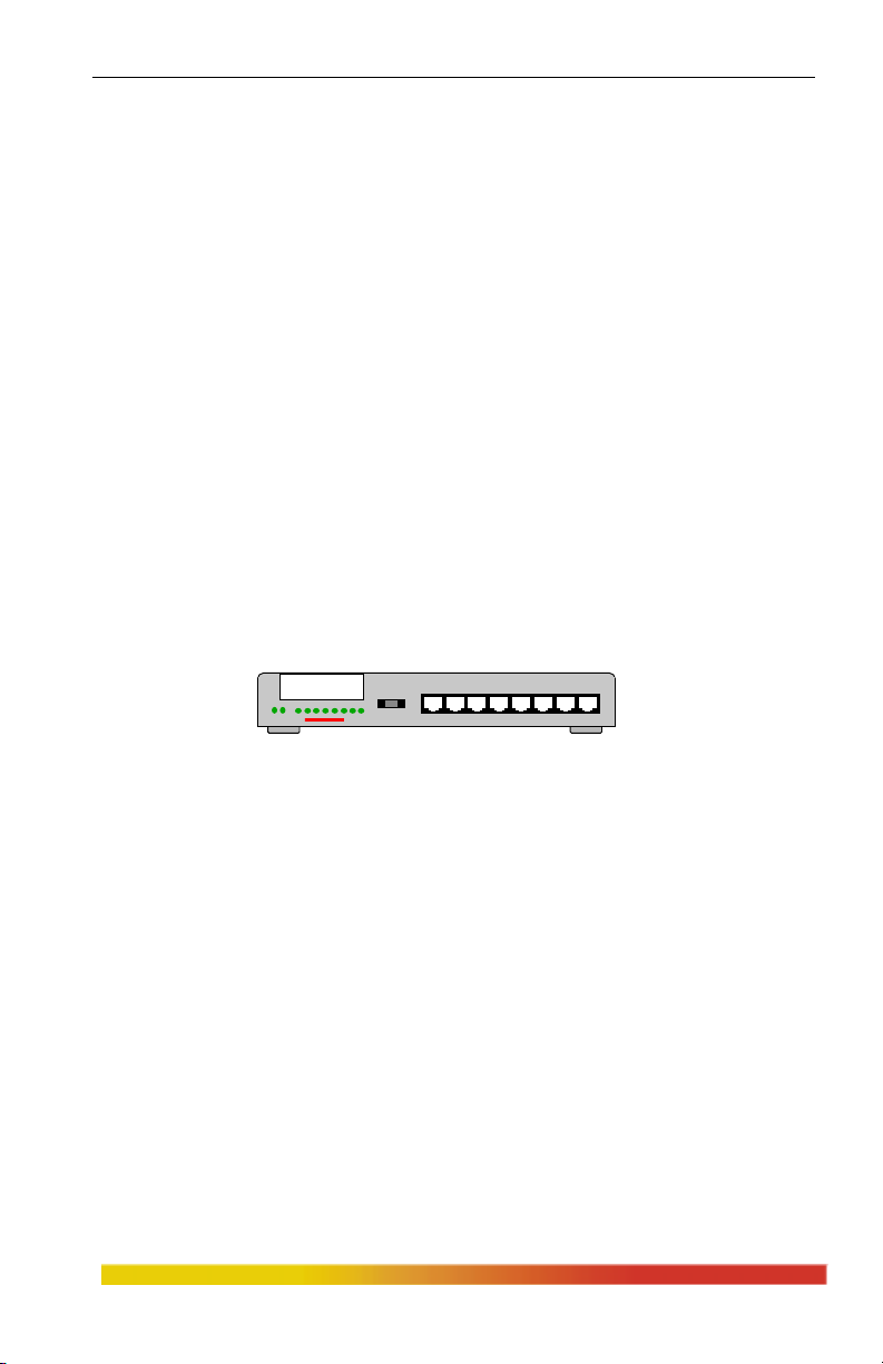
Figure 2.2.1b shows the rear-mounted AUI port. This is the base or default
configuration for the Magnum 1008. The basic AUI (standard female) port may be used
for a direct connection with an AUI drop cable or for connection to any media type via
an external mini-transceiver.
When using standard AUI cabling to connect to other Ethernet devices, it is
important to consider the AUI segment length, including any cascading. Refer to
Section 3.3.2 for detailed information on the AUI port, connector pins and standard
cable length requirements.
www GarrettCom com
..
5
Page 12
Magnum 1000 Workgroup Hubs Installation and User Guide (04/02)
AC Power
115 - 230 VAC
Figure 2.2.1b: Rear view - Magnum 1008 Workgroup Hub with the basic AUI port
As an alternative to the basic AUI port, it is possible (at the time of initial
order) to replace the basic AUI rear port with any Magnum Port Module (PM). (See
Figure 2.2.1c). This option gives the Magnum 1008 great flexibility to easily conform
to any standard Ethernet media environment. When configured with a Repeater Port
Module (RPM), the rear port can be used for direct connection to any standard Ethernet
media. With a Bridge Port Module (BPM), the rear port is used to bridge-isolate the
Magnum 1008 from the rest of the network, increasing bandwidth for both the local
users and the rest of the network. Refer to Section 2.4 for Magnum Port Module
information. (NOTE: The Magnum 1008’s basic AUI port is NOT an RPM-AUI, it is
simply an AUI port without any
LEDs).
AC Power
115 - 230 VAC
Basic AUI Port
Port Module
(RPM-FST shown)
Figure 2.2.1c: Rear view - Magnum 1008 Workgroup Hub configured with PM
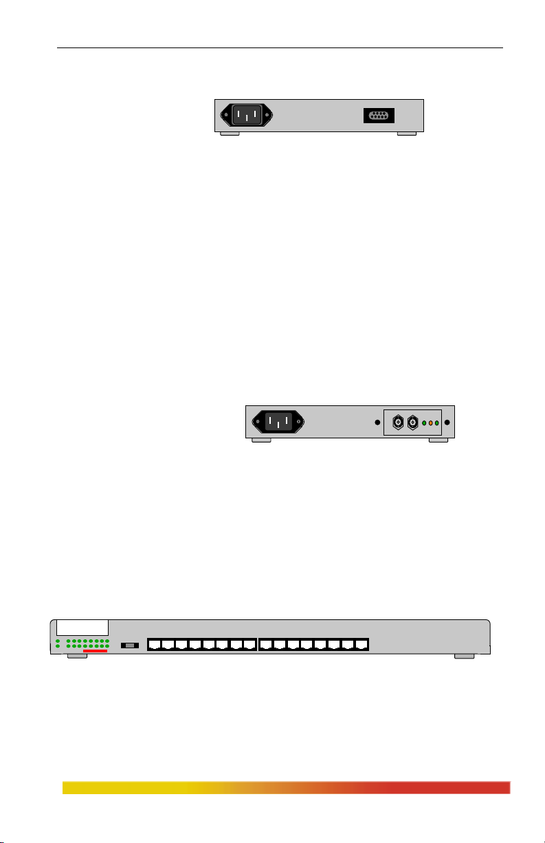
2.2.2 Magnum 1016 and 1024 Workgroup Hubs
The Magnum 1016 Workgroup Hub is equipped with 16 front-mounted,
shielded RJ-45 ports, 1 rear-mounted basic AUI port and 1 rear Bonus Port slot (see
Figure 2.2.2a). The left-most front RJ-45 port (port 1) is equipped with a slide switch to
allow cascading or an up-link without a crossover cable.
Magnum 1016
Workgroup Hub
GARRETT
1 2 3 4 5 6 7 8 9 10 11 12 13 14 15 16
Figure 2.2.2a: Front view - Magnum 1016 Workgroup Hub
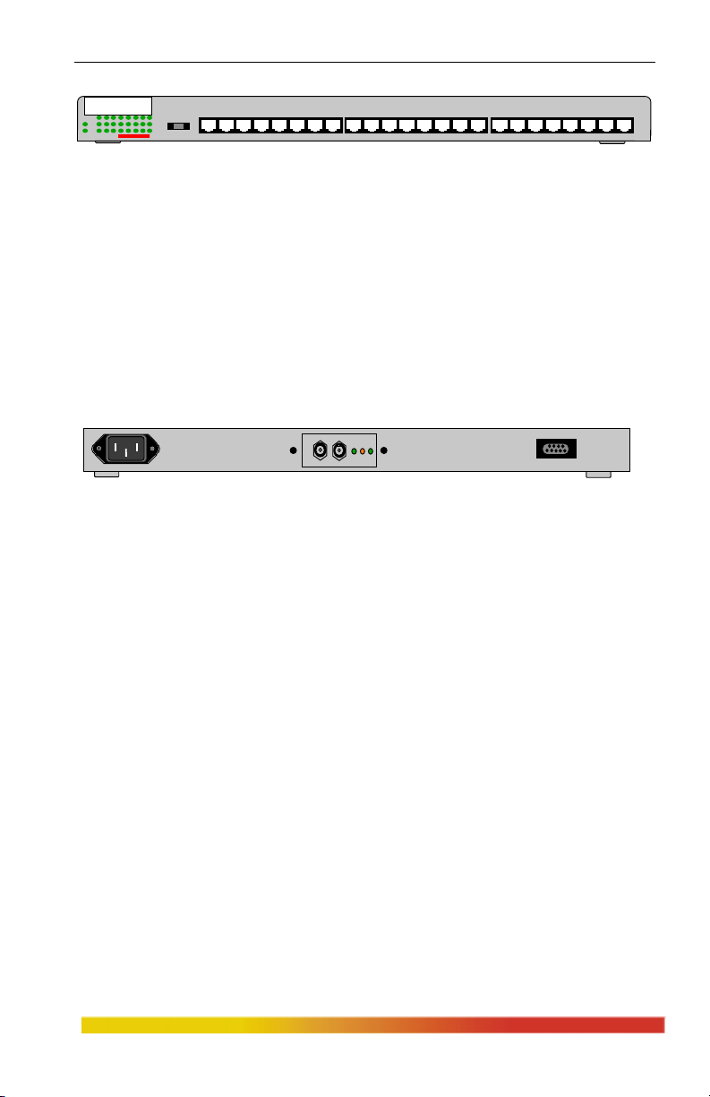
The Magnum 1024 Workgroup Hub is equipped with 24 front-mounted,
shielded RJ-45 ports, 1 rear-mounted AUI port and 1 rear Bonus Port slot (see Figure
2.2.2b).
www GarrettCom com
..
6
Page 13
Magnum 1000 Workgroup Hubs Installation and User Guide (04/02)
Magnum 1024
Workgroup Hub
GARRETT
In the rear, the basic AUI (standard female) port, shown in Figure 2.2.2c, may
be used for a direct connection with an AUI drop cable or for connection to any media
type via an external mini-transceiver. When using standard AUI cabling to connect to
other Ethernet devices, it is important to consider the AUI segment length, including any
cascading. Refer to Section 3.3.2 for detailed information on the basic AUI port,
connector pins and standard cable length requirements. (NOTE: The basic AUI port is
NOT an RPM-AUI, it is simply an AUI port without any LEDs.)
1 2 3 4 5 6 7 8 9 10 11 12 13 14 15 16 17 18 19 20 21 22 23 24
Figure 2.2.2b: Front view - Magnum 1024 Workgroup Hub
AC Power
115 - 230 VAC
Configurable Bonus Port
(RPM-FST Shown)
Basic AUI Port
Figure 2.2.2c: Rear view - Magnum 1016 and 1024 Workgroup Hubs
The Bonus Port slot of a Magnum 1016 or 1024, shown in Figure 2.2.2c, may
be optionally configured with any Magnum Port Module (PM). This option gives the
Magnum 1016s and 1024s great flexibility to easily conform to any standard Ethernet
media environment. When configured with a Repeater Port Module (RPM), the rear
port can be used for direct connection to any standard Ethernet media. With a Bridge
Port Module (BPM), the rear port is used to bridge-isolate the Magnum hub from the
rest of the network, increasing bandwidth for both the local users and the rest of the
network. Refer to Section 2.4 for Magnum Port Module information.
Status LEDs are located on the front panel of both the 1016 and 1024 for
convenient monitoring of PWR, ACT and LINK (per port). Magnum 1016 and 1024
hubs have auto-ranging internal power supplies, are suitable for table-top-, wall-, or
rack-mounting. Rack-mount “ears” are supplied with both the Magnum 1016 and
Magnum 1024 Workgroup Hubs.
www GarrettCom com
..
7
Page 14
Magnum 1000 Workgroup Hubs Installation and User Guide (04/02)
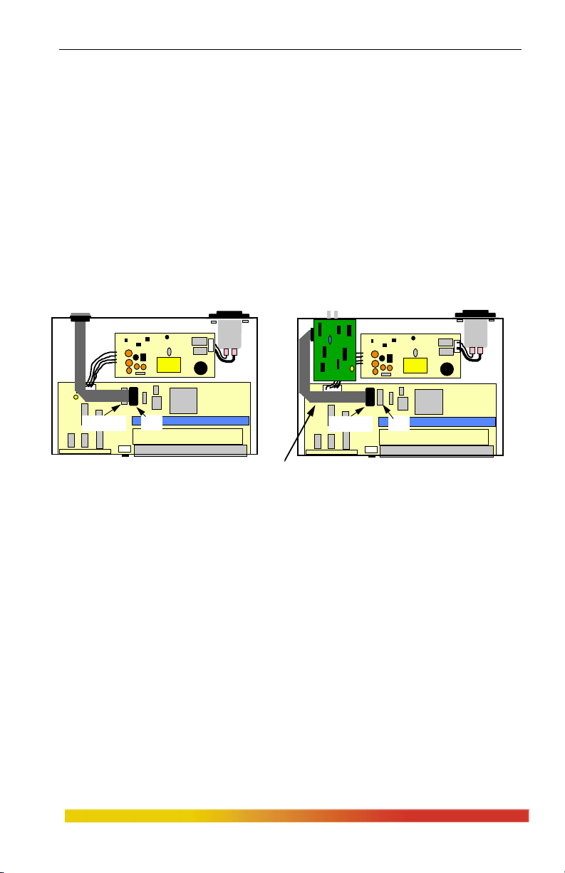
2.3 Internal Connections, basic AUI Port and Port Modules
Figure 2.3a shows the internal layout of the Magnum 1008 for each of the two
rear port configuration options (see section 2.2.1). Unless otherwise specified at the
time of order, the Magnum 1008 is shipped with a basic AUI port. For greater
application flexibility, any of the Magnum PMs may be specified at the time of order for
factory configuration. It is also possible for the rear port to be re-configured in the field
by a trained technician to exchange or add Port Modules.
NOTE: When changing from the basic AUI port to a Port Module option in the field, it
is necessary to have a Port Module connector cable (part number CBL-PM available as a
spare part from GCI) in addition to the desired PM.
Basic AUI port
P1-RPM P1
NOTE:
Use P1 for Basic AUI port
Use P1-RPM for PM
P1
Optional PM card
(BPM shown)
P1-RPM
PM Ribbon cable with 16 pin headers.
(Included only when PM is factory installed.
May be ordered separately as part # CBL-PM)
Figure 2.3a: Model 1008 Internal Connections, Basic AUI port and Port Module
Figure 2.3b shows the internal layout of the Magnum 1016 and 1024
Workgroup Hubs. (The Model 1024 is shown in the figure, but all rear port connections
are identical for the Model 1016). One rear port always has the basic AUI port in it.
The bonus port slot, in the center of the chassis rear, is available for configuring any
PM. For application flexibility, any of the Magnum PMs may be specified on an order
for factory configuration in the bonus port slot. It is also possible for the bonus port to
be re-configured in the field by a trained technician to exchange or add Port Modules.
NOTE: When adding a Port Module option to the Bonus Port slot in the field, it is
necessary to have a Port Module connector cable (part # CBL-PM available as a spare
part from GCI) in addition to the desired PM. See also Section 2.4.12, Special Option.
www GarrettCom com
..
8
Page 15

Magnum 1000 Workgroup Hubs Installation and User Guide (04/02)
Bonus port for optional
Basic AUI port
J1-RPM
PM card (BPM shown)
J1
J4
J4
NOTE:
Use J1 and J4 for Basic AUI ports
Use J1-RPM and J4-RPM for PMs
J4-RPM
J4-RPM
PM Ribbon cable with 16 pin headers.
(Included only when PM is factory installed.
May be ordered separately as part # CBL-PM)
Figure 2.3b: Model 1024 Internal Connections, Basic AUI port and Bonus Port
2.4 Bonus Port Configuration Options - RPMs and BPMs
Magnum 1000 Workgroup Hubs may be configured with any Repeater Port
Module (RPM) or Bridge Port Module (BPM) in the rear bonus port. (For the 1008, this
is done by exchanging the basic AUI port for a Port Module). An RPM may be used to
provide connectivity, such as to a backbone, via any standard Ethernet media. A BPM
may be used to provide local-bridge isolation for the 1000 Workgroup Hub’s users.
RPMs are available for the following six Ethernet connector types: BNC
(ThinNet or 10BASE2), AUI (10BASE5 or ThickNet, DB-15 female for most
transceiver connections), DTE (DB-15 male-AUI for direct connects), ST (Ethernet
multi-mode Fiber ST), SMF (Ethernet single-mode Fiber), and RJ-45 (10BASE-T UTP
and STP). They are shown in Figure 2.4a.
Figure 2.4a: Magnum RPM Cards: RPM-BNC, RPM-AUI,
RPM-DTE, RPM-FST, RPM-SMF & RPM-TP.
www GarrettCom com
..
9
Page 16

Magnum 1000 Workgroup Hubs Installation and User Guide (04/02)
BPMs are available for the following four Ethernet media connector types:
BNC (ThinNet or 10BASE2), AUI (10BASE5 or ThickNet, DB-15 female for most
transceiver connections), ST (Ethernet multi-mode Fiber ST), and RJ-45 (10BASE-T
UTP and STP). They are shown in Figure 2.4b.
Figure 2.4b:
Magnum BPM
Cards: BPM-TP,
BPM-BNC, BPM-
ST, BPM-AUI
Magnum Port Modules provide an optional electronic assembly and media
connector for the Magnum 1000 Hubs’ bonus port slots, and are not functional as stand-
alone units. Figure 2.4c shows the physical dimensions of the Port Modules.
BPM
RPM
Approx. 3 inches (7.6 cm)
Approx. 2 inches (5.1 cm)
Figure 2.4c: Physical Dimensions of Magnum Port Modules
Each Port Module is normally factory installed in Magnum 1000 Hub units.
Alternatively, PMs may sometimes be installed in the field by a trained technician.
The following is a detailed description of each Port Module.
www GarrettCom com
..
Approx. 2 inches (5.1 cm)
Approx. 2.25 inches (5.2 cm)
10
Page 17

Magnum 1000 Workgroup Hubs Installation and User Guide (04/02)
2.4.1 RPM-BNC
The Magnum RPM-BNC repeater module is equipped with a standard
10BASE2 coax connector. This RPM performs full IEEE 802.3 repeater functionality
and is used for 10BASE2 ThinNet (commonly referred to as BNC) connections.
The RPM-BNC module is designed with a special switch-selectable internal
termination function that eliminates the need for a "tee" connector and a 50 ohm
terminator. To take advantage of internal termination, the slide switch should be in the
"DOWN" (or right-side) position. In this configuration, the 10BASE2 segment is
directly attached to the BNC port where it is internally terminated. When the switch is
in the "UP" (or left-side)
position, the BNC port
requires a "tee" connector
Standard BNC
10BASE2 Connector
(not supplied) and a 50
ohm terminator for
proper termination.
1
Certain applications may
require a "tee" connector,
used as a tap, to allow the 10BASE2 coax segment to continue on past the RPM-BNC
connection.
Magnum BPM-BNC
Internal Termination
Slide Switch
Partition LED
1
2
Receive LED
2
The RPM-BNC module includes one partition (PART) and one receive (RX)
LED, which are visible from the exterior. (The PART LED is inoperative on Model
1000 Hubs because the logic necessary to drive the LED is not included in the design.)
The RX LED illuminates GREEN intermittently to indicate data is being received.
Important Note: for the RPM-BNC Termination Switch -
DOWN (or right): Internally Terminated
UP (or left): Requires "T" Connector.
2.4.2 RPM-AUI
This module is equipped with a 15 pin female AUI connector and a slide-lock,
and performs full IEEE 802.3 repeater functionality. It is used to provide connectivity
with a 10BASE5 (ThickNet) backbone or to any AUI segments. A transceiver is
required when connecting to a ThickNet segment and the RPM-AUI supports this
convention.
www GarrettCom com
The RPM-AUI is also a "universal" Ethernet media interface as it may be
..
11
Page 18

Magnum 1000 Workgroup Hubs Installation and User Guide (04/02)
used with a variety of different mini-transceivers to provide connectivity to any media
type.
The RPM-AUI card is equipped with Partition (PART) and Receive (RX)
LEDs. The RX LED functions the same as the RX LEDs of the RPM-BNC. The PART
LED is inoperative on Model 1000 Workgroup Hubs. (Section 2.4.1 above).
The Magnum RPM-AUI
Partition LED
card is also used for connecting
Ethernet devices using standard
Standard 15-pin
female AUI,
with slide-lock
1
2
Receive LED
AUI cabling. In this situation, it is
important to consider the AUI
segment length or distance to the
1
2
attached device, including any
cascading. Refer to Section 3.3.2
Magnum RPM-AUI
for detailed information on the AUI
port, connector pins, and cable length requirements.
2.4.3 RPM-DTE
The Magnum RPM-DTE is a module equipped with a 15-pin male DTE
connector with lock posts. (The RPM-DTE is a mating connector for the RPM-AUI
which has a 15-pin female connector and slide locks. The pin assignments of the two
are the same). The RPM-DTE card
is designed to support direct
connections (no transceiver
Partition LED
1
2
Receive LED
Standard 15-pin
male "AUI"
required) using AUI drop cables to
any device that is equipped with an
AUI port. Examples of such devices
1
2
include servers, routers, bridges,
hubs, and UNIX workstations.
Magnum RPM-DTE
www GarrettCom com
..
12
Page 19

Magnum 1000 Workgroup Hubs Installation and User Guide (04/02)
2.4.4 RPM-FST (Fiber ST, Twist-lock Connector)
The Magnum RPM-FST is a multi-mode fiber optic module equipped with a
dual ST-type connector. It functions as an IEEE 802.3 full repeater to support 10BASE-
FL and FOIRL network segments. When used for 10BASE-FL segments, this module
supports fiber optic transmission
distances up to 2000m. For FOIRL
applications, it supports fiber segments
of up to 1000m in length. The RPM-
FST includes full transceiver
functionality and does not require an
external transceiver device. In
addition to Partition (which is
inoperative on Model 1000 Hubs) and
Receive (RX) LEDs, a LINK LED indicates proper
Magnum RPM-FST connectivity with the remote device.
NOTE: The RPM-FST circuit board contains a six pin jumper which controls
the intensity of the transmitted signal. By default, the jumper is placed across pins 1 and
2. The jumper may be set as follows to
accommodate distances of up to 4 km:
JUMPER ACROSS DISTANCES
SUPPORTED
1 - 2 0 - 2 km*
3 - 4 0.5 - 3 km**
5 - 6 1.5 - 4 km**
* When distances of less than 2 km are needed, the
jumper should be placed across pins 1 and 2.
** When fiber cable distances of more than 2 km are selected, the minimum cable length must also
be increased, as shown in the table above.
2.4.5 RPM-FSC(Fiber SC, Snap-in
Connector)
The Magnum RPM-FSC is also a
multi-mode fiber optic repeater module. Its
functionality is exactly like the RPM-FST, but
it is equipped with an SC-type "snap-in"
connector. Please refer back to section 2.4.4
for details.
10BASE-FL, FOIRL
ST Connectors
1
3
1
1
2
3
2
LINK Partition Receive
LINK
Partition
Receive
2
DEFAULT
10BASE-FL, FOIRL
SC Connectors
1
3
3
1 2
3 4
5 6
J1
Magnum RPM-FSC
2
www GarrettCom com
..
13
Page 20

Magnum 1000 Workgroup Hubs Installation and User Guide (04/02)
2.4.6 RPM-SMF (Single-mode Fiber)
The Magnum RPM-SMF is a single-mode fiber optic module equipped with a
dual ST-type connector. It functions as a full repeater to support single-mode fiber
networks. The RPM-SMF supports fiber optic transmission distances of up to 10 Km.
The RPM-SMF includes full
transceiver functionality and does
not require an external
transceiver device.
This module is
equipped with PART, RX, and
LINK LEDs identical to those of
3
the RPM-FST. To distinguish
the single-mode RPM-SMF from the multi-mode
RPM-FST, the label “Sgl. M.” is at the top of the faceplate of the RPM-SMF. As an
additional indicator, a multi-mode TX port emits light (red in color) that is in the visible
spectrum and which can be seen by looking into the port with the power on and with no
cable connected. The single-mode TX port emits light outside of the visible spectrum
and will always look dark to the human eye.
Single-mode
ST Connectors
1
1
2
LINK Partition R eceive
2
3
Magnum RPM-SMF
Note: Be sure to use single-mode fiber optic cable with this module (see Section 3.8.9).
Single-mode fiber cable has a smaller diameter than multi-mode fiber cable (2/15 - 8/60
microns for single-mode, 50/125 or 62.5/125 microns for multi-mode, where xx/xx are
the diameters of the core and the core plus the cladding respectively).
NOTE: The RPM-SMF circuit board contains a six-pins (three positions)
jumper, but the jumper is only to be placed across pins 5 & 6 for single-mode. The
other jumper positions are not used for single-mode fiber.
JUMPER ACROSS DISTANCES
SUPPORTED
1 - 2 not used
3 - 4 not used
5 - 6 0 - 10 km
www GarrettCom com
..
DEFAULT
1 2
3 4
5 6
J1
14
Page 21

Magnum 1000 Workgroup Hubs Installation and User Guide (04/02)
2.4.7 RPM-TP (Twisted Pair)
The Magnum RPM-TP card supports Ethernet twisted pair segments of any
standard length. It is equipped with a single RJ-45 connector. The RJ-45 connector is
shielded to minimize emissions and will allow both unshielded twisted pair (UTP) and
shielded twisted pair (STP)
segment connections.
The RPM-TP
module is also equipped with
a slide switch to allow for
cascaded or up-link
connections. This feature
eliminates the need for a
special twisted pair crossover cable.
With the switch in the UP position, the RPM-TP port is used for up-link
connections (i.e.: a connection to another repeater or hub typically.) When used for
segments going to workstations and other user device connections, the switch should be
in the DOWN position. Proper switch position can be verified by noting that the port’s
LINK LED will illuminate when proper link is established.
MDI-X
Cross-Over
Slide Switch
1
3
1
Magnum RPM-TP
Shielded RJ-45
Connector
2
LINK Partition Receive
2
3
The RPM-TP will support 10BASE-T unshielded twisted pair wiring (UTP)
environments with maximum segment distances up to 100m (325 ft.), or shielded
twisted pair wiring (STP) of 150m (500 ft.). This module is designed with internal
transceiver functionality. The RPM-TP has LINK, PART (inoperative on Model 1000
Hubs), and RX LEDs.
Important Note: For the RPM-TP MDI-X Crossover Switch -
DOWN(or Right) for workstations and user connections.
UP (or Left) for Up-Link connections to other hubs, etc.
The RJ-45 pins normally (TP crossover switch DOWN) are per the standard for hubs-tousers twisted pair wiring: 1 = receive+, 2 = receive-, 3 = transmit+, 6 = transmit-, other
pins not used. When the TP crossover switch is UP, the pins of the RJ-45 port are per
the standard for up-links using twisted pair wiring, i.e., the transmit and the receive pairs
are exchanged: 1 = transmit+, 2 = transmit-, 3 = receive+, 6 = receive-, other pins not
used.
www GarrettCom com
..
15
Page 22

Magnum 1000 Workgroup Hubs Installation and User Guide (04/02)
2.4.8 BPM-BNC
The Magnum BPM-BNC
Standard BNC
10BASE2 Connector
bridge module is equipped with a
standard 10BASE2 coax connector.
This BPM is self-learning and filters
1
and forwards packets at full Ethernet
wire speed. This module is used for
10BASE2 ThinNet (commonly
referred to as BNC) connections and is
Magnum BPM-BNC
designed to isolate the local segment (i.e., the users and devices connected to the
Magnum unit housing the BPM) from the connecting network (i.e., the users and
devices connected through the BPM’s media connector).
The BPM-BNC module is designed with a special switch -selectable internal
termination function that eliminates the need for a "tee" connector and a 50 ohm
terminator. For switch details, refer to RPM-BNC, section 2.4.1.
module includes an FWD-I LED and an FWD-X LED, which are visible
exterior. The FWD-I LED blinks GREEN to indicate that packets are being forwarded
INTO the local Magnum hub. The FWD-X LED blinks GREEN to indicate that packets
are being forwarded OUT of the local Magnum hub.
Internal Termination
Slide Switch
FWD-X LED
1
FWD-I LED
2
2
The BPM-BNC
from the
2.4.9 BPM-AUI
This local-bridge module is
Standard 15-pin
female AUI
with slide-lock
FWD-X LED
1
FWD-I LED
2
equipped with a 15 pin female AUI
connector and a slide-lock. It is self-
learning and filters and forwards
1
2
packets at full Ethernet wire speed. It
is used to provide segment isolation
from a 10BASE5 (ThickNet) backbone or any
Magnum BPM-AUI
AUI segment. A transceiver is required when connecting to a ThickNet segment and
the BPM-AUI supports this convention.
The BPM-AUI is equipped with one FWD-I LED and one FWD-I LED, which
are identical to those of the BPM-BNC (see Section 2.4.9). The BPM-AUI connector
supports standard IEEE signals, which are summarized in Table 3.3.2 of Section 3.3.2.
www GarrettCom com
..
16
Page 23

Magnum 1000 Workgroup Hubs Installation and User Guide (04/02)
2.4.10 BPM-FST
The Magnum BPM-FST is a multi-mode fiber optic local-bridge module
equipped with a dual ST-type connector. It is self-learning and filters and forwards
packets at full Ethernet wire speed. When used for 10BASE-FL segments, this module
supports fiber optic transmission
distances up to 2000m. For FOIRL, it
supports fiber segments of up to
1000m in length. The BPM-FST
includes full transceiver functionality
and does not require an external
transceiver device. The BPM-FST has
three status LEDs. FWD-I and FWD-X
are identical to those of the BPM-BNC (Section 2.4.9). In addition, this module has a
GREEN LINK LED, that is always on when the link is operational.
10BASE-FL, FOIRL
ST Connectors
2
1
3
1
2
3
Magnum BPM-FST
FWD-X LED
FWD-I LED
LINK LED
2.4.11 BPM-TP
The Magnum BPM-TP
card is equipped with a single RJ-
45 connector and supports standard
MDI-X Cross-over
Slide Switch
Shielded RJ-45
Connector
FWD-X LED
1
FWD-I LED
2
LINK LED
3
1
3
2
length Ethernet twisted pair
segments. The RJ-45 connector is
shielded to minimize emissions
and allows both unshielded twisted pair
Magnum BPM-TP
(UTP) and shielded twisted pair (STP) segment connections.
The BPM-TP module is also equipped with a Media Dependent Interface-
Crossover (MDI-X) slide switch to allow for
cascaded connections. This feature
eliminates the need for a special twisted pair crossover cable (see RPM-TP, 2.4.7).
The BPM-TP will support 10BASE-T unshielded twisted pair wiring (UTP)
with maximum segment distances of 100m (325 ft.), or shielded twisted pair wiring
(STP) of 150m (500 ft.). This module is designed with internal transceiver
functionality. The status LEDs are the same as those of the BPM-FST (Section 2.4.10).
www GarrettCom com
..
17
Page 24

Magnum 1000 Workgroup Hubs Installation and User Guide (04/02)
2.4.12 Special Option -- Second Bonus Port (Models 1016 and 1024)
In special cases, it may be desirable to configure the Magnum 1016 or 1024
Workgroup Hub with a second Port Module. The 1016 and 1024 Workgroup Hubs were
designed to accommodate such a configuration, and the second Bonus Port may be
configured by a trained technician and connected into header J1-RPM. In order to
install a second PM, it is necessary to replace the factory-installed Basic AUI Port,
connected into header J1, with the desired Port Module. This procedure requires a Port
Module connector cable (ordered separately as part number PM-CBL, or equal), and is
similar that of the Model 1008 change from a Basic AUI to a PM. Request special quote
for factory installation of a second Port Module for Models 1016 and 1024.
NOTE: LEDs of the 2nd PM (connected in J1-RPM) may not be functional.
NOTE: Due to the Bridge Port Module functionality, only one BPM may be
configured per Workgroup Hub.
www GarrettCom com
..
18
Page 25

Magnum 1000 Workgroup Hubs Installation and User Guide (04/02)
2.5 Features and Benefits
! Low cost, stand-alone 10BASE-T connectivity
Operating in a stand-alone environment as a self-sufficient network
device, Magnum 1000 Workgroup Hubs offer a low cost method of
providing small- to medium-size offices and workgroups access to
standard Ethernet networking services.
! Workgroup connectivity into a larger network
Magnum 1000 Workgroup Hubs provide a low cost method of providing
workgroups with local networking services and also interconnection into
a larger network via the up-link, the AUI port or the bonus port.
! Rear Bonus Port Provides Connectivity or Local Isolation
The rear Bonus Port of the Magnum 1000 Workgroup Hubs may be
optionally configured with any one of ten Magnum Port Modules. When
configured with an RPM, the hub may be connected to any standard
Ethernet media. Configuration with a BPM allows local-bridge isolation
of the Magnum 1000 segment from the connected network.
! Inter-operable with other Ethernet Devices
Magnum 1000 Workgroup Hubs are completely inter-operable with any
Ethernet-compliant network device. Each Magnum 1000 Hub is fully
compliant with IEEE 802.3 specifications for 10 Mbps CSMA/CD
operation, allowing full Ethernet network compatibility.
! Robust Network Operations
Magnum 1000 Workgroup Hubs use a "star" network topology and have
automatic per port partitioning and re-connection. A faulty segment is
isolated from the rest of the network, avoiding most network downtime.
! LEDs Simplify Network Installation and Maintenance
Magnum 1000 Workgroup Hubs are equipped with front-mounted LEDs
to provide status about basic network activity. The per port LINK LEDs
offer a very simple way to verify connections at both ends of each
attached twisted-pair cable.
! Internal "Universal" Power Supply with Auto-ranging
An internal universal AC power supply allows any Magnum 1000
Workgroup Hub unit to be used throughout the world. The power cable
attaches via a standard recessed IEC-type connector in the rear
www GarrettCom com
..
19
Page 26

Magnum 1000 Workgroup Hubs Installation and User Guide (04/02)
2.6 Applications
Magnum 1000 Workgroup Hubs offer a great deal of flexibility and are
easily used within a variety of Ethernet environments. Magnum Workgroup Hubs will
often be used to support small- to medium-size networks operating in stand-alone
configurations, as shown in Figure 2.6a. The number of users would likely not exceed
twenty or so, including assorted network devices such as printers and servers.
Figure 2.6a: Magnum 1000 Workgroup Hub in stand-alone configuration.
RPM-BNC
BNC Segment
Server
M
a
n
g
u
m
1
0
0
0
W
o
r
g
k
o
r
u
p
H
u
b
G
A
R
R
T
E
T
1
2
3
Ma
g
n
u
W
o
r
k
g
r
o
Up-link
G
A
R
R
E
T
T
connection
1024
4
5
6
7
8
9
0
1
1
1
2
1
1
3
1
4
5
1
1
6
1
7
1
8
1
9
2
0
2
1
2
2
2
3
4
2
AUI port
Magnum 1000 Workgroup Hub
m
1
0
0
0
u
p
H
u
b
1
2
3
4
1008
5
6
7
8
9
1
0
Ma
n
g
u
m
1
0
0
0
W
o
k
r
g
o
r
u
p
H
u
b
G
R
A
R
E
T
T
M
a
g
u
n
m
1
0
0
0
W
o
r
k
g
r
o
u
p
H
u
b
1
2
3
4
5
6
A
G
R
R
E
T
T
1
1
1
2
1
3
1
4
1
5
1
6
1
7
1
8
1
9
2
0
7
8
2
1
1016
9
1
0
1
1
2
2
RPM-BNC
1
2
3
1
4
1
1
5
1
6
2
3
2
4
Server
Figure 2.6b: Magnum 1000 Workgroup Hubs with backbone interconnections.
Magnum 1000 Hubs can also be used to extend an existing network of any
standard Ethernet media. Figure 2.5b shows two workgroups connected to a ThinNet
(10BASE2) segment. One of the workgroups is comprised of two Magnum 1000’s
cascaded by means of the up-link switch of a port 1 (for details on the up-link switch,
refer to section 3.3.1, “Connecting Twisted Pair (RJ-45, Unshielded or Shielded). Each
workgroup is connected to the ThinNet through a rear-mounted BNC-type RPM. In
addition, the basic AUI port may be used to connect any standard device, such as the
server shown in the figure above.
www GarrettCom com
..
20
Page 27

Magnum 1000 Workgroup Hubs Installation and User Guide (04/02)
When network performance and bandwidth are an issue, Magnum 1000’s can
be configured with a Bridge Port Module, as shown in Figure 2.6c. In this diagram,
M
a
g
n
u
m
7
0
0
X
M
i
n
i
o
C
n
e
c
n
t
a
r
o
t
r
e
u
G
R
A
R
E
T
T
Fiber BPM
M
a
n
g
u
m
1
0
0
0
W
o
r
g
k
o
r
u
p
H
u
b
1
2
G
A
R
R
T
E
T
1016
b
Fiber BPM
1008
3
4
5
6
7
8
9
0
1
1
1
1
2
3
1
4
1
1
5
1
6
Ma
n
g
u
m
1
0
0
0
W
o
k
r
g
o
r
u
p
H
u
A
G
R
R
E
T
T
Server
Server
Fiber BPM
Fiber BPM
Ma
g
u
n
m
1
0
0
0
W
o
r
g
k
r
o
u
p
H
u
Ma
g
n
u
m
1
0
0
0
W
o
r
k
g
o
r
u
p
H
u
b
1
2
3
G
R
A
R
E
T
T
1024
4
5
6
7
8
9
1
0
1
1
1
2
1
3
1
4
1
5
1
6
1
7
1
8
9
1
2
0
2
1
2
2
3
2
4
2
b
1
2
3
A
G
R
R
E
T
T
Server
1016
4
5
6
7
8
9
1
0
1
1
1
2
1
3
1
4
1
5
1
6
Server
Figure 2.6c: Magnum 1000 Workgroup Hubs with local-isolation via rear BPMs.
each local-bridge-isolated workgroup is connected to a central concentrator through a
BPM with a fiber connector. Since each workgroup has its own printer and server, most
of the network traffic is kept local (i.e., is contained inside of each Magnum 1000 Hub
segment by the BPMs) and does not consume bandwidth on the rest of the network.
Refer to section 4.2, “Magnum 1000 BPM Local Bridge Functionality”, for more
information about the operation of the BPMs.
www GarrettCom com
..
21
Page 28

Magnum 1000 Workgroup Hubs Installation and User Guide (04/02)
3.0 INSTALLATION
This section gives instructions for installing the Magnum 1000 Workgroup
Hubs, and for connecting the various Ethernet media.
3.1 Table-Top or Rack-Mount
Installation of a Magnum 1000 Workgroup Hub is a very simple procedure.
Magnum hubs are easily mounted in a rack or on a table-top. When properly installed,
the front-mounted LED status indicators should be in plain view and easy to read.
Rack mounting
installation requires a
special rack-mount
Magnum 1008 Workgroup Hub
Rack Mount Brackets (Optional)
Magnum 1000
Workgroup Hub
GARRETT
bracket. (This is
included with models
1016 and 1024. For
model 1008, order part #
1008-RMB.) The
brackets easily attach to
Magnum 1000
Workgroup Hub
GARRETT
Magnum 1000
Workgroup Hub
GARRETT
1 2 3 4 5 6 7 8 9 10 11 12 13 14 15 16
1 2 3 4 5 6 7 8 9 10 11 12 13 14 15 16 17 18 19 20 21 22 23 24
Magnum 1016 and 1024 Workgroup Hubs
Rack Mount Brackets (Included)
the hub, which is then
installed in any standard 19 inch rack.
Figure 3.1: Magnum 1000’s,
Rack-mount Brackets
3.2 Powering the Magnum 1000 Workgroup Hub
Magnum 1000 Workgroup Hubs incorporate an internal universal power
supply, and have a recessed male IEC connector for the AC power cord at the right-rear.
A six-foot 115 VAC 60 Hz power cord is supplied with each unit shipped within the
United states and Canada.
Each Magnum 1000 Workgroup Hub’s auto-ranging power supply supports
installation environments where the AC voltage is from 90 to 260 volts with a power
input frequency between 47 and 63 Hz, and will consume a maximum of 20 watts
(estimated). In order to power down the unit, simply unplug either end of the power
cable.
When connecting various Ethernet media, there is no need to power down the
unit. Individual segments of any media type can be connected or disconnected without
concern for AC power-related problems or damage to the unit.
www GarrettCom com
..
22
Page 29

Magnum 1000 Workgroup Hubs Installation and User Guide (04/02)
3.3 Ethernet Media Connections
The Magnum 1000 workgroup Hub may be used as a stand-alone hub serving
the needs of a small to medium size workgroup or may be connected to a larger network
environment. In either case, user connectivity is achieved using twisted pair wiring,
Cat. 3 or Cat 5, UTP or STP. There may be some cases where a user device will be
connected via the AUI or Bonus Port.
In applications where Magnum hubs are used to provide workgroup services
within a larger network system, the rear port(s) may be connected into a larger network,
rather than being used to connect to a user.
The various media types supported and their corresponding IEEE 802.3
standards and connector types are as follows:
Media IEEE Standard Connector PM type
ThinNet 10BASE2 BNC RPM-BNC, BPM-BNC
ThickNet 10BASE5 AUI (female) RPM-AUI, BPM-AUI
Drop Cable 10BASE5 DTE (male) RPM-DTE
Twisted Pair 10BASE-T RJ-45 RPM-TP, BPM-TP
Fiber (mm1) FOIRL ST RPM-FST, RPM-SMF, BPM-FST
Fiber (mm1) 10BASE-FL ST or SC RPM-FST, RPM-SMF, BPM-FST
Fiber (sgl.m2) * ST RPM-SMF
1
mm = multi-mode
2
sgl.m = single-mode
* 10 Mb operation not currently standardized by IEEE
Instructions for connecting the Magnum 1000 Workgroup Hub to each of the
standard Ethernet types are given below.
3.3.1 Connecting Twisted Pair (RJ-45, Unshielded or Shielded)
The following procedure describes how to connect a 10BASE-T twisted pair
segment to the RJ-45 port on the front panel of the hub or to the RPM-TP or BPM-TP.
The procedure is the same for both unshielded and shielded twisted pair segments.
1. Using standard 10BASE-T media, insert either end of the cable with an RJ-45
plug into the RJ-45 connector. Note that, even though the TP connector is shielded,
either unshielded or shielded 10BASE-T cables and wiring may be used.
2. Connect the other end of the cable to the corresponding device.
3. When proper connection and power have been established, the port’s LINK LED
will illuminate GREEN.
www GarrettCom com
..
23
Page 30

Magnum 1000 Workgroup Hubs Installation and User Guide (04/02)
NOTE: Port 1 of the Magnum 1000 Workgroup Hub (and the Magnum RPM-TP and
BPM-TP) are equipped with a cross-over slide switch to accommodate
repeater-to-repeater connections without special cross-over connectors.
Set the slide switch to the “left” (for port 1) or “down” (for PM-TP) position
for normal twisted pair cable segments from the hub port to a user device. Set
the slide switch to the “right” (port 1) or “up” (for PM-TP) position for
cascaded or up-link segment connections to another repeater or hub in the
network. Verify proper switch position by noting that the port’s LINK LED
will illuminate when proper link is established.
3.3.2 Connecting ThickNet 10BASE5 (AUI)
Using the steps below as a guide, attach a new or existing 10BASE5 ThickNet
drop-cable directly to the AUI connector on the rear of the Magnum 1000 Workgroup
Hub or on the RPM-AUI or BPM-AUI port.
1. Plug the male end of the cable into the female AUI connector on the Magnum
1000 or PM-AUI card.
2. Engage the AUI connector slide lock to insure maximum connectivity.
3. Connect the opposite end of the cable into a network AUI port. (This
could be a network backbone transceiver, a hub or fan-out with an AUI
port, or an AUI Port Module in a concentrator.)
The AUI port may also used for connecting to other Ethernet devices using
standard AUI cabling. In this type of situation, it is important to consider the AUI
segment length to the attached device, including any cascading.
The maximum transmission distance between a backbone transceiver
equipped with an AUI connector and the AUI port of the Magnum 1000 will vary.
According to Ethernet standards, when an AUI cable is used to connect the Magnum
1000 directly to a backbone transceiver, the maximum AUI segment length of 50m (165
ft.) is allowed. If the Magnum 1000 is connected to a transceiver that has been cascaded
from another transceiver, the maximum AUI segment length is reduced as stated below.
Important Note: The maximum transmission distance is decreased by 6m
(20 ft.) for every additional level of network transceiver device "dropped" or "cascaded"
from the original backbone transceiver tap.
The RPM-AUI connector supports standard IEEE signals, which are
summarized in Table 3.3.2.
www GarrettCom com
..
24
Page 31

Magnum 1000 Workgroup Hubs Installation and User Guide (04/02)
Table 3.3.2: AUI Pin Assignments
Pin Function Pin Function
1 Control In Circuit Shield 10 Data Out Circuit B
2 Control In Circuit A 11 Data Out Circuit Shield
3 Data Out Circuit A 12 Data In Circuit B
4 Data In Circuit Shield 13 Voltage Plus (+)
5 Data In Circuit A 14 Voltage Shield
6 Voltage Common 15 Control Out Circuit B
7 Control Out Circuit A SHELL Protective Ground
8 Control Out Circuit Shield (conductive shell)
9 Control In Circuit B
NOTES: 1) Voltage Plus (pin #13) and Voltage Common (pin # 6) use a single
twisted pair in the AUI cable.
2) Pins 4, 8, 11 and 14 may be connected to pin #1.
3.3.3 Connecting ThinNet 10BASE2 (BNC)
Connect the ThinNet coax cable to the BNC connector on the Magnum RPM-
BNC or BPM-BNC card in the same manner as is done for any standard BNC
connection. The PM-BNC port is specially equipped with an internal termination switch
on the front of the card (see Section 4.1 for a description of this switch). This eliminates
the need to use a "tee" connector when the BNC cable is ending at the connection to this
PM. Some applications may require a "tee" connector, used as a tap, to allow the
10BASE2 coax segment to continue on past the PM-BNC connection.
3.3.4 Connecting Drop Cable 10BASE5 (DTE)
Using the steps below as a guide, attach the 10BASE5 drop-cable directly to the
DTE connector on the RPM-DTE port.
1. Plug the female end of the cable into the male DTE connector on the RPM-DTE
card.
2. Engage the AUI connector slide lock (on the cable) to insure maximum
connectivity.
3. Connect the opposite end of the cable into a network AUI port. (This could be a
server, router, bridge, hub, or UNIX workstation.)
3.3.5 Connecting Fiber Optic 10BASE-FL and FOIRL (ST-type, “Twist-Lock")
The following procedure applies to FOIRL and 10BASE-FL applications using
an RPM-ST or BPM-ST card with ST-type fiber connectors. (The primary difference
between FOIRL and 10BASE-FL for users is the maximum distance allowed. 10BASE-
FL is used for a fiber segment length of up to 2000m, while FOIRL is used for fiber
segments of up to 1000m in length.)
1. Before connecting the fiber optic cable, remove the protective dust caps from the
tips of the connectors on the PM-ST. Save these dust caps for future use.
www GarrettCom com
..
25
Page 32

Magnum 1000 Workgroup Hubs Installation and User Guide (04/02)
2. Wipe clean the ends of the dual connectors with a soft cloth or lint-free lens
tissue dampened in alcohol. Make certain the connectors are clean before connecting.
Note: One strand of the duplex fiber optic cable is coded using color bands
at regular intervals; you must use the color-coded strand on the
associated ports at each end of the fiber optic segment.
3. Connect the Transmit (TX) port (light colored post) on the Magnum PM-FST to
the Receive (RX) port of the remote device. Begin with the color-coded strand
of the cable for this first TX-to-RX connection.
4. Connect the Receive (RX) port (dark colored post) on the PM-FST to the
Transmit (TX) port of the remote device. Use the non-color coded fiber strand
for this.
5. The LINK LED on the front of the PM-FST will illuminate when a proper
connection has been established at both ends (and when power is ON in the
unit). If LINK is not lit after cable connection, the normal cause is improper
cable polarity. Swap the fiber cables at the Port Module connector to remedy
this situation.
3.3.6 Connecting Fiber Optic (SMA-type, "Screw-on")*
The same five-step procedure as for fiber ST-type applies to FOIRL and
10BASE-FL applications using an RPM-SMA card used with SMA-type fiber
connectors. Follow the five steps as described in the Section 3.3.5 above.
When connecting fiber media to SMA connectors, do not over-tighten but
rather simply "finger tighten" these connections. Do not use a heavy tool (such as a
wrench) to tighten the fiber optic connectors as this might cause damage and result in
operating problems. Improper and excessive tightening may impair data transmission.
* The RPM-SMA is only available via special order.
3.3.7 Connecting Single-Mode Fiber Optic (SMF)
When using the RPM-SMF, be sure to use single-mode fiber cable. Single-
mode fiber cable has a smaller diameter than multi-mode Fiber cable (2/15 - 8/60
microns for single-mode, 50/125 or 62.5/125 microns for multi-mode where xx/xx are
the diameters of the core and the core plus the cladding respectively). Because of this,
single-mode fiber allows full bandwidth at longer distances, and may be used to connect
nodes up to 10 Km apart. For operation with standard half-duplex Ethernet, collision
domain and / or power budget limitations may apply for distances over 5Km. Check
your single-mode configuration with an experienced network designer when you use
extended distances.
The same five-step procedure for multi-mode fiber ST-type applies to single-
mode fiber connectors. Follow the five steps listed in Section 3.3.5 above.
www GarrettCom com
..
26
Page 33
Magnum 1000 Workgroup Hubs Installation and User Guide (04/02)
T
,
,
3.3.8 Power Budget Calculations for Magnum 1000 Series RPM’s with Fiber
Media
Receiver Sensitivity and Transmitter Power are the parameters necessary to
compute the power budget. To calculate the power budget of different fiber media
installations using Magnum products, the following equations should be used:
OPB (Optical Power Budget) = PT(min) - PR(min)
where PT = Transmitter Output Power, and PR = Receiver Sensitivity
Worst case OPB = OPB - 1dB(for LED aging) - 1dB(for insertion loss)
Worst case distance = {Worst case OPB, in dB} / [Cable Loss, in dB/Km]
where the “Cable Loss” for 62.5/125 and 50/125µm (M.m) is 2.8 dB/km,
and the “Cable Loss” for 100/140 (Multi-mode) is 3.3 dB/km,
and the “Cable Loss” for 9/125 (Single-mode) is 0.5 dB/km
The following data has been collected from component manufacturer’s (HP’s and
Siemens’) web sites and catalogs to provide guidance to network designers and
installers.
Fiber
Module
Port
Speed,
Std.
Mode
Std.
km
fdx
(hdx)
Wave
-
length
Cable
Size
µm
X’mitr
Output
P
dB
T
R’cvr
Sens.
P
R
dB
Worst
OPB,
dB
Worst*
distance
Km, fdx
typical
OPB,
dB
nm
RPM-MST,
MSC
RPM-
SMF (ST)
10 Mb
FL
10 Mb
FL
Multi-
mode
Single-
mode
2
(2)
10
(5)
62.5/125
850
100/140
50/125
1300 9/125 -30 -39 7 14 13 26
-15.0
-9.5
-19.5
-31
-31
-31
14
19.5
9.5
5.9
3.4
5
17
23.5
13.5
* Note: The use of either multi-mode or single-mode fiber to operate at 100Mbps speed
over long distances (i.e., in excess of approx. 400 meters) can be achieved only
if the following factors are both applied:
• The 100Mb fiber segment must operate in full-duplex (FDX) mode, i.e. the
full-duplex (factory default) setting for 100Mbps fiber ports must be used,
and
• The worst-case OPB of the fiber link must be greater than the fiber cable’s
passive Attenuation.
(Attenuation = Cable loss + LED aging loss + Insertion loss + safety factor)
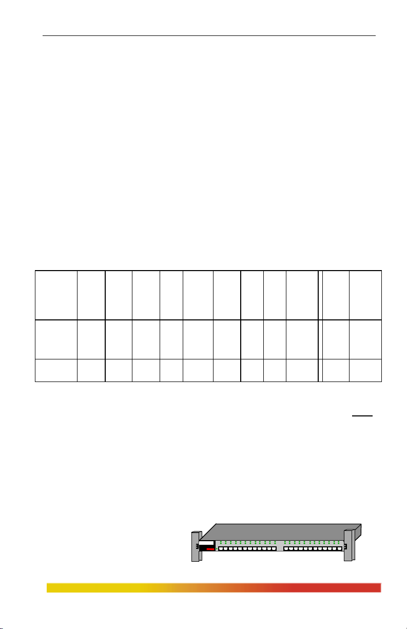
3.3.9 Rack-mounting
Installation of a Magnum
Magnum 3000
1000 Series Hub in a 19” rack is a
Stackable Hub
GARRET
simple procedure. The units are 1U
(1.75”) high. When properly installed, the front-mounted LED status indicators should
www GarrettCom com
..
27
typical*
distance
Km, fdx
6
7
4.8
Page 34

Magnum 1000 Workgroup Hubs Installation and User Guide (04/02)
g
g
g
be in plain view and easy to read. Rack-mount installation requires special rack-
mounted brackets and screws (included with each 1000 series unit). The brackets attach
to the front sides of the Hub, which is then fastened into a standard 19” rack.
The 23” brackets and ETSI brackets are also available (optional) for Rackmounting purpose with Magnum 1000 Series Hubs. The 23”
brackets are more popular in
TELCO Industry and
consider as a standard for
Rack-mounting purpose. The
23” brackets are mainly being
used for Huge rack-mounting
frame to provide more secure
and stability to the unit in the
TELCO industry.
The ETSI
(European standard) brackets
are moreover looks similar to
the 23”
brackets and mostly used in
the ETSI standard industry.
The optional 23” brackets
and the ETSI brackets
come in a package along
with the necessary screws for the convenient to the customer.
Magnum 1000
1 2 3 4 5 6 7 8 9 10 11 12 13 14 15 16 17 1 8 19 20 21 22 23 24
Workgroup Hub
Ma
num 1000
1 2 3 4 5 6 7 8 9 10 11 12 13 14 15 16 17 1 8 19 20 21 22 23 24
Workgroup Hub
Ma
num 1000
1 2 3 4 5 6 7 8 9 10 11 12 13 14 15 16 17 1 8 19 20 21 22 23 24
Workgroup Hub
num 1000
Ma
1 2 3 4 5 6 7 8 9 10 11 12 13 14 15 16 17 1 8 19 20 21 22 23 24
Workgroup Hub
4.0 OPERATION
The Magnum 1000 Workgroup Hubs operate as full-function Ethernet
repeaters. They are compliant with IEEE 802.3 specifications for CSMA/CD 10 Mbps
operation, and support standard IEEE defined media inclusive of 10BASE-T, 10BASE-
FL, FOIRL, 10BASE2, and 10BASE5. The following describes the basic functionality.
4.1 Magnum 1000 Repeater Functionality
Repeater Functionality: Each hub port operates in conjunction with the
controller functions of the Magnum 1000 Hub’s base unit, functioning together as a
fully compliant Ethernet repeater.
www GarrettCom com
..
28
Page 35

Magnum 1000 Workgroup Hubs Installation and User Guide (04/02)
Collisions: When carrier is detected simultaneously on multiple ports, a jam
pattern is generated on each port to create a collision condition. When a collision signal
from one port is detected, it generates a jam pattern to the other ports.
Partitioning and Re-Connection: Magnum 1000 Hubs will automatically
partition any port where 32 consecutive collisions occur or after 6.5 milliseconds (msec)
of continuous transmissions. Network integrity is checked every 800 msec and segment
re-connection occurs after one 512-bit packet is transmitted without an error.
Fragment Extension: Magnum 1000 Hubs will automatically add bits to a
received data packet of less than 96 bits (a "fragment") so that the minimum output
packet to the other port is 96 bits long.
Preamble Regeneration: Magnum 1000 Hubs will add bits to the preamble
so that the output packet contains a minimum of a 64-bit preamble.
Status LEDs: Each Magnum 1000 Workgroup Hub is designed with front
panel LEDs to allow for quick visual assessment of the operational condition of the hub
and the network. Each Magnum 1000 Hub is equipped with PWR, ACT, and LINK
LEDs. Bonus Port RPMs are also equipped with status LEDs (see Section 2.4).
PWR LED: Illuminates GREEN to indicate proper operation of the
internal power supply.
ACT LED: Illuminates GREEN to indicate “activity”, i.e., that the hub
is processing network packets. Normally flashes to indicate data traffic.
LINK LEDs: Illuminates GREEN when connectivity is established
between the hub and the attached device. Each RJ-45 port is represented
by its own LINK LED. LINK should always be on during normal
operation. LINK is OFF if connectivity or power is lost anywhere along
the segment.
www GarrettCom com
..
29
Page 36

Magnum 1000 Workgroup Hubs Installation and User Guide (04/02)
4.2 Magnum 1000’s with BPM Local Bridge Functionality
When configured with a BPM, a Magnum 1000 Workgroup Hub and its
attached devices are bridge-isolated from the network segment connected through the
BPM. The bridge functionality of the BPM bridge modules is described here.
1. Bridge Functions: Each BPM card contains a compact local bridge
module which filters and forwards packets at full Ethernet wire speed. These
micro-bridges are self learning and have small (256 user) address tables.
Packet filter/forward decisions are made based on whether the
packet source is internal (originates within the local Magnum 1000) or
external (originates from upstream
on the attached segment). If the
packet’s source is internal, it is
forwarded to the outside only if the
destination address is not in the
address table. Figure 4.2a shows
an internal packet being forwarded
to the external segment.
Packet Forwarded
Internal packets
are forwarded when
the destination is
NOT IN the address
table.
FWD-X LED “ON”
Figure 4.2a: Internal
Figure 4.2b show the
cases where an internal packet is
filtered. When the packet’s
source is external, it is forwarded
to the inside only if the
destination address is in the
address table.
The filter/forward Figure 4.2b: Internal Packet Filtered
handling of external packets
are shown in figures 4.2c and
4.2d respectively. When an
internal packet’s source
address is not already in the
address table, it is written
www GarrettCom com
..
Internal packets
are filtered when
the destination is
IN the address
table.
External packets
are forwarded when
the destination is
IN the address
table.
FWD-I LED “ON”
30
Page 37

Magnum 1000 Workgroup Hubs Installation and User Guide (04/02)
there. This happens when a node first sends Figure 4.2c: External Packet
Forwarded
a packet upon bridge initialization.
Note, therefore, that the address
table learns only internal addresses, i.e.,
those connected via the inside of the local
Magnum 1000, a number typically well
External packets
are filtered when
the destination is
NOT IN the
address table.
under the 256 table addresses size. Should
the table become full, the BPM will clear all
entries in the table by reinitializing itself.
When
an external packet’s source address
is in the address table, it is purged. Figure 4.2d: External Packet Filtered
This can occur if a node has physically moved to a different location.
A summary of the filtering, forwarding, and address table
maintenance performed by the BPMs is shown in Table 4.2.
Table 4.2: BPM Functionality
Packet Source Destination Address Table Filter/Forward
Source Address Address Maintenance Action
Internal Not in table Not in table Add source to table Forward
Internal Not in table In table Add source to table Filter
Internal In table Not in table Nothing Forward
Internal In table In table Nothing Filter
External Not in table Not in table Nothing Filter
External Not in table In table Nothing Forward
External In table Not in table Purge source from table Filter
External In table In table Purge source from table Forward
2. Throughput Increase: By using a BPM to isolate a user group segment
having significant local traffic, it is possible to increase overall network
throughput. For example, a segment containing a group of workstations and
servers may have heavy local traffic, but only a small amount of traffic that is
www GarrettCom com
..
31
Page 38

Magnum 1000 Workgroup Hubs Installation and User Guide (04/02)
directed outside the segment. A BPM connecting this segment to the rest of
the network, as shown in Figure 4.2e, will keep the local segment traffic
isolated from the rest of the network, thus increasing the effective bandwidth
on both the local segment and the rest of the network.
Local nodes with heavy local traffic,
connected to front RJ-45 ports
Magnum 1024 Workgroup Hub
Local segment isolation
through Bonus Port configured
with BPM (BPM-FST shown)
Figure 4.2e: Local Segment Isolation with a Bridge Port Module (BPM)
3. Bridge Transparency: The BPMs are transparent to both the users and
the application software.
4. LINK and Traffic Status: The Magnum BPM-TP and BPM-FST
indicate link integrity with an LED. This LINK LED is normally lit. An unlit
LINK LED indicates a broken cable or loss of power at some point in the
segment. All BPMs have FWD-I and FWD-X status LEDs. The FWD-I LED
flashes when packets are forwarded into the local segment. The FWD-X LED
flashes when packets are forwarded out of the local segment.
5. Self-test Diagnostics: A Magnum BPM requires 15 seconds upon power-
up before bridging services are available. During this time, the BPM performs
an internal self-test.
4.3 Power Requirements
Magnum 1000 Hubs are designed with internal auto-ranging AC power supply
units for efficiency and for simplicity of installation and operation. See Section 3.2,
“Powering the Magnum 1000 Workgroup Hub” for detailed information on the AC
power needed. See Section 1.1, “Technical Specifications: Power Supply (Internal)” for
detailed information on the internal power supply units.
For optional 48VDC internal power supply information, see Appendix B.
www GarrettCom com
..
32
Page 39

Magnum 1000 Workgroup Hubs Installation and User Guide (04/02)
5.0 TROUBLESHOOTING
All Magnum Ethernet products are designed to provide reliability and
consistently high performance in all network environments. The installation of Magnum
1000 series workgroup hub is a straightforward procedure (see INSTALLATION,
Section 2.6); the operation is also straightforward and is discussed in Section 4.
Should problems develop during installation or operation, this section is
intended to help locate, identify and correct these types of problems. Please follow the
suggestions listed below prior to contacting your supplier. However, if you are unsure
of the procedures described in this section or if the Magnum 1000 series workgroup hub
is not performing as expected, do not attempt to repair the unit; instead contact your
supplier for assistance or contact GarrettCom Customer Support.
5.1 Before Calling for Assistance
1. If difficulty is encountered when installing or operating the unit, refer back to
the Installation Section of the applicable chapter of this manual. Also check
to make sure that the various components of the network are interoperable.
2. Check the cables and connectors to ensure that they have been properly
connected and the cables/wires have not been crimped or in some way
impaired during installation. (About 90% of network downtime can be
attributed to wiring and connector problems.)
3. Make sure that an AC power cord is properly attached to each Magnum 1000
series workgroup hub unit. Be certain that each AC power cord is plugged
into a functioning electrical outlet. Use the PWR LEDs to verify each unit is
receiving power.
4. If the problem is isolated to a network device other than the Magnum 1000
series workgroup hub product, it is recommended that the problem device is
replaced with a known good device. Verify whether or not the problem is
corrected. If not, go to Step 5 below. If the problem is corrected, Magnum
1000 series workgroup hub and its associated cables are functioning properly.
5. If the problem continues after completing Step 4 above, contact your supplier
of the Magnum 1000 series workgroup hub unit or if unknown, contact
GarrettCom, Inc.by fax, phone or email (support@garrettcom.com) for
assistance.
www GarrettCom com
..
33
Page 40

Magnum 1000 Workgroup Hubs Installation and User Guide (04/02)
5.2 When Calling for Assistance
Please be prepared to provide the following information.
1. A complete description of the problem, including the following points:
a. The nature and duration of the problem;
b. Situations when the problem occurs;
c. The components involved in the problem;
d. Any particular application that, when used, appears to create the problem;
2. An accurate list of GarrettCom product model(s)involved, with serial
number(s). Include the date(s) that you purchased the products from your
supplier.
3. It is useful to include other network equipment models and related hardware,
including personal computers, workstations, terminals and printers; plus, the
various network media types being used.
4. A record of changes that have been made to your network configuration prior
to the occurrence of the problem. Any changes to system administration
procedures should all be noted in this record.
5.3 Return Material Authorization (RMA) Procedure
All returns for repair must be accompanied by a Return Material
Authorization (RMA) number. To obtain an RMA number, call GarrettCom
Customer Service at (510) 438-9071 during business hours in California or email to
support@garrettcom.com). When calling, please have the following information
readily available:
Name and phone number of your contact person.
Name of your company / institution
Your shipping address
Product name
Serial Number (or Invoice Number)
Packing List Number (or Sales Order Number)
Date of installation
Failure symptoms, including a full description of the problem.
www GarrettCom com
..
34
Page 41

Magnum 1000 Workgroup Hubs Installation and User Guide (04/02)
GarrettCom will carefully test and evaluate all returned products, will
repair products that are under warranty at no charge, and will return the warrantyrepaired units to the sender with shipping charges prepaid (see Warranty
Information, Appendix A, for complete details). However, if the problem or
condition causing the return cannot be duplicated by GarrettCom, the unit will be
returned as:
No Problem Found.
GarrettCom reserves the right to charge for the testing of non-defective
units under warranty. Testing and repair of product that is not under warranty will
result in a customer (user) charge.
5.4 Shipping and Packaging Information
Should you need to ship the unit back to GarrettCom, please follow these
instructions:
1. Package the unit carefully. It is recommended that you use the original
container if available. Units should be wrapped in a "bubble-wrap" plastic
sheet or bag for shipping protection. ( You may retain all connectors and
this Installation Guide.)
CAUTION: Do not pack the unit in Styrofoam "popcorn" type packing
material. This material may cause electro-static shock damage to the unit.
2. Clearly mark the Return Material Authorization (RMA) number on the
outside of the shipping container.
3. GarrettCom is not responsible for your return shipping charges.
4. Ship the package to:
GarrettCom, Inc.
213 Hammond Ave.
Fremont, CA 94539
Attn.: Customer Service
APPENDIX A: WARRANTY INFORMATION
GarrettCom, Inc. warrants its products to be free from defects in
materials and workmanship for a period of three (3) years from the date of
shipment by GarrettCom.
During this warranty period, GarrettCom will repair or, at its option,
replace components in the products that prove to be defective at no charge other
than shipping and handling, provided that the product is returned pre-paid to
GarrettCom.
This warranty will not be effective if, in the opinion of GarrettCom, the
product has been damaged by misuse, misapplication, or as a result of service or
modification other than by GarrettCom.
GarrettCom reserves the right to make a charge for handling and
inspecting any product returned for warranty repair which turns out not to be
faulty.
Please complete the warranty card as this acts as a product registration,
and mail it to GarrettCom within two weeks of your purchase.
www GarrettCom com
..
35
Page 42

Magnum 1000 Workgroup Hubs Installation and User Guide (04/02)
APPENDIX B : Internal DC Power Supply Option
B1.0 SPECIFICATIONS - FOR MAGNUM 1000 WORKGROUP HUBS
Power Supply (Internal -48 VDC Option)
DC Power Connector: 3 terminals: “-“, “GND”, “+”
Input Voltage: 36 - 70 VDC (auto-ranging)
Power Consumption: Magnum 1000’s Hubs: 10 watts typical,
20 watts max. P.S. rating
Power Supply (Internal 24 VDC Option)
DC Power Connector: 3 terminals: “-“, “GND”, “+”
Input Voltage: 20 - 40 VDC (auto-ranging)
Power Consumption: Magnum 1000’s Hubs: 10 watts typical,
20 watts max. P.S. rating
Power Supply (Internal 125 VDC Option)
DC Power Connector: 3 terminals: “-“, “GND”, “+”
Input Voltage: 120 - 160 VDC (auto-ranging)
Power Consumption: Magnum 1000’s Hubs: 10 watts typical,
20 watts max. P.S. rating
With the exception of the power supply, all specifications and functions of
Magnum 1000 Workgroup Hubs-48VDC, 24VDC & 125VDC models are identical
to those listed in the main manual.
B2.0 -48VDC, 24VDC & 125VDC POWER OPTION, THEORY OF
OPERATION
The -48VDC, 24VDC & 125VDC power option is designed using diodes
inside on each DC power input line behind the two external power connection terminals,
so that the power from an external
source can only flow into the hub. This
allows the hub to operate only
whenever DC power is correctly
A+
A-
GND
HUB
SUPPLY
+
-
CHASSIS
GND
FUSE
applied to the two inputs. It protects
the hub from incorrect DC input connections. An incorrect polarity connection, for
example, will neither effect the hub, nor its power supply internally, nor will it blow the
fuse in the internal power supply.
Disconnecting the power source is used for powering the hub on and off when
it is placed into or taken out of service.
www GarrettCom com
..
36
Page 43

Magnum 1000 Workgroup Hubs Installation and User Guide (04/02)
B3.0 APPLICATIONS
Magnum 1000 Workgroup Hubs are easily installed in a variety of
applications where -48VDC, 24VDC & 125VDC power is used as the primary power
source. The -48VDC, 24VDC & 125VDC power configuration provides an Ethernet
networking solution utilizing a special DC internal power supply in hubs having a
proven reliability record.
The solution is particularly useful in the telecommunication industry, where it
is common for facilities to operate on -48VDC power. Such companies include regular
and wireless telephone service providers, Internet Service Providers (ISPs), other
communication companies, and firms supplying network management and operations
monitoring equipment. In addition, many high-availability equipment services, such as
in broadcasters, publishers, heavy industrial plants, brokerage firms and others, often
use a battery backup system to maintain operations in the event of a power failure.
The 24VDC & 125VDC solution are particularly useful in the
Industrial environment, where it is common facilities to operate on 24VDC & 125VDC
power. The 125VDC solution is mainly used in Utilities Industries, such as Electric
substation, Electrical generating plant etc. Whereas 24VDC application is mainly in the
Industrial environment, such as chemical plants, paper mill, stone quarrying plant,
wastewater treatment Plant etc
B4.0 INSTALLATION
This section describes the installation of the -48VDC, 24VDC &125VDC
power source leads to the -48VDC, 24VDC & 125VDC power terminal block on the
Magnum 1000’s. (see figure below).
_
GND
Figure B4.1: -48VDC Terminal
+
Block on Magnum 1000’s-48VDC
The -48VDC, 24VDC &
125VDC terminal block on the
Magnum 1000’s is located on the rear
of the unit and is equipped with three
36-70VDC
(3) screw-down lead posts. The leads
are identified as negative (-), positive (+), and chassis ground (GND). The connection
procedure is straightforward. Simply connect the DC leads to the Switch’s power
terminals, positive (+) and negative (-) screws. The use of Ground (GND) is optional; it
connects to the Switch chassis. Ensure that each lead is securely tightened.
www GarrettCom com
..
37
Page 44

Magnum 1000 Workgroup Hubs Installation and User Guide (04/02)
Note: Before connecting to Terminal Block of –48VDC, 24VDC or 125VDC,
always use a digital voltmeter to measure the output voltage of the power supply and
determine the lead which is more “+ve potential Lead”. The more “+ve” voltage
terminal lead from 48V or –48V Power supply must be connected to the post labeled
“+”.
The GND can be hooked at the last.
Disconnecting the DC power source is used to remove the unit from service, and as a
power-down to RESET the hub’s electronics if needed.
B4.1 UL Requirements
1. Minimum 14 AWG cable for connection to a Centralized DC power source.
2. Fastening torque of the lugs on the terminal block: 9 inch pound max.
3. Centralized DC Power Source cable securement, use at least four cable ties to
secure the cable to the rack at least 4 inches apart with the first one located
within 6 inches of the terminal block.
B5.0 OPERATION
Operation of the Magnum 1000’s with the optional -48VDC, 24VDC &
125VDC power supply is identical to that of the standard AC-powered models.
B6.0 ORDERING INFORMATION
To order the optional -48VDC power supply factory installed, add a suffix of
“-48VDC” after the product’s standard model #. Example:
Similarly for “24VDC”: Magnum 1016-24VDC.
Magnum 1016-48VDC.
B7.0 TROUBLESHOOTING
Please refer to Section 6.0 for troubleshooting
www GarrettCom com
..
38
 Loading...