

Page 1

™
G2000
Cockpit Reference Guide for the Model T240
Integrated Flight Deck
Page 2

Page 3

FLIGHT INSTRUMENTS
ENGINE INDICATION SYSTEM
NAV/COM/TRANSPONDER/AUDIO PANEL
AUTOMATIC FLIGHT CONTROL SYSTEM
FMS NAVIGATION
FLIGHT PLANNING
PROCEDURES
HAZARD AVOIDANCE
ADDITIONAL FEATURES
ABNORMAL OPERATION
ANNUNCIATIONS & ALERTS
APPENDIX
INDEX
Page 4

Page 5

Copyright © 2012-2013 Garmin Ltd. or its subsidiaries. All rights reserved.
This manual reflects the operation of System Software version 1308.07 or later for the Cessna
Corvalis T240. Some differences in operation may be observed when comparing the information
in this manual to earlier or later software versions.
Garmin International, Inc., 1200 East 151st Street, Olathe, Kansas 66062, U.S.A.
Tel: 913/397.8200 Fax: 913/397.8282
Garmin AT, Inc., 2345 Turner Road SE, Salem, OR 97302, U.S.A.
Tel: 503/391.3411 Fax 503/364.2138
Garmin (Europe) Ltd, Liberty House, Bulls Copse Road, Hounsdown Business Park,
Southampton, SO40 9RB, U.K.
Tel: 44/0870.8501241 Fax: 44/0870.8501251
Garmin Corporation, No. 68, Jangshu 2nd Road, Shijr, Taipei County, Taiwan
Tel: 886/02.2642.9199 Fax: 886/02.2642.9099
For after-hours emergency, aircraft on ground (AOG) technical support for Garmin panel mount
and integrated avionics systems, please contact Garmin’s AOG Hotline at 913.397.0836.
Web Site Address: www.garmin.com
Except as expressly provided herein, no part of this manual may be reproduced, copied,
transmitted, disseminated, downloaded or stored in any storage medium, for any purpose
without the express written permission of Garmin. Garmin hereby grants permission to
download a single copy of this manual and of any revision to this manual onto a hard drive or
other electronic storage medium to be viewed for personal use, provided that such electronic
or printed copy of this manual or revision must contain the complete text of this copyright
notice and provided further that any unauthorized commercial distribution of this manual or any
revision hereto is strictly prohibited.
Garmin® , FliteCharts®, and SafeTaxi® are registered trademarks of Garmin Ltd. or its subsidiaries.
These trademarks may not be used without the express permission of Garmin. G2000™, Garmin
SVT™, and Garmin ESP™ are trademarks of Garmin Ltd. or its subsidiaries.
NavData® is a registered trademark of Jeppesen, Inc.; Stormscope® is a registered trademark
of L-3 Communications.
SiriusXM Weather and SiriusXM Satellite Radio are provided by SiriusXM Satellite Radio, Inc.
AC-U-KWIK® is a registered trademark of Penton Business Media Inc.
Page 6

AOPA Membership Publications, Inc. and its related organizations (hereinafter collectively
“AOPA”) expressly disclaim all warranties, with respect to the AOPA information included in this
data, express or implied, including, but not limited to, the implied warranties of merchantability
and fitness for a particular purpose. The information is provided “as is” and AOPA does not
warrant or make any representations regarding its accuracy, reliability, or otherwise. Under
no circumstances including negligence, shall AOPA be liable for any incidental, special or
consequential damages that result from the use or inability to use the software or related
documentation, even if AOPA or an AOPA authorized representative has been advised of the
possibility of such damages. User agrees not to sue AOPA and, to the maximum extent allowed
by law, to release and hold harmless AOPA from any causes of action, claims or losses related
to any actual or alleged inaccuracies in the information. Some jurisdictions do not allow the
limitation or exclusion of implied warranties or liability for incidental or consequential damages
so the above limitations or exclusions may not apply to you.
AC-U-KWIK and its related organizations (hereafter collectively “AC-U-KWIK Organizations”)
expressly disclaim all warranties with respect to the AC-U-KWIK information included in this
data, express or implied, including, but not limited to, the implied warranties of merchantability
and fitness for a particular purpose. The information is provided “as is” and AC-U-KWIK
Organizations do not warrant or make any representations regarding its accuracy, reliability, or
otherwise. Licensee agrees not to sue AC-U-KWIK Organizations and, to the maximum extent
allowed by law, to release and hold harmless AC-U-KWIK Organizations from any cause of
action, claims or losses related to any actual or alleged inaccuracies in the information arising
out of Garmin’s use of the information in the datasets. Some jurisdictions do not allow the
limitation or exclusion of implied warranties or liability for incidental or consequential damages
so the above limitations or exclusions may not apply to licensee.
May, 2013 190-01264-01 Rev. A Printed in the U.S.A.
Page 7

Warnings, Cautions & Notes
WARNING: Navigation and terrain separation must NOT be predicated upon
the use of the terrain avoidance feature. The terrain avoidance feature is NOT
intended to be used as a primary reference for terrain avoidance and does
not relieve the pilot from the responsibility of being aware of surroundings
during flight. The terrain avoidance feature is only to be used as an aid for
terrain avoidance. Terrain data is obtained from third party sources. Garmin
is not able to independently verify the accuracy of the terrain data.
WARNING: The displayed minimum safe altitudes (MSAs) are only advisory
in nature and should not be relied upon as the sole source of obstacle and
terrain avoidance information. Always refer to current aeronautical charts
for appropriate minimum clearance altitudes.
WARNING: Do not use outdated database information. Databases used in
the G2000 system must be updated regularly in order to ensure that the
information remains current. Pilots using any outdated database do so
entirely at their own risk.
WARNING: Do not use basemap (land and water data) information for
primary navigation. Basemap data is intended only to supplement other
approved navigation data sources and should be considered as an aid to
enhance situational awareness.
WARNING: Traffic information shown on system displays is provided as an
aid in visually acquiring traffic. Pilots must maneuver the aircraft based only
upon ATC guidance or positive visual acquisition of conflicting traffic.
WARNING: Do not use data link weather information for maneuvering in, near,
or around areas of hazardous weather. Information contained within data
link weather products may not accurately depict current weather conditions.
WARNING: Do not use the indicated data link weather product age to
determine the age of the weather information shown by the data link weather
product. Due to time delays inherent in gathering and processing weather
data for data link transmission, the weather information shown by the data
link weather product may be significantly older than the indicated weather
product age.
190-01264-01 Rev. A
Garmin G2000 Cockpit Reference Guide for the Cessna Corvalis T240
Page 8
Warnings, Cautions & Notes
WARNING: Do not rely on information from the lightning detection system
display as the sole basis for hazardous weather avoidance. Range limitations
and interference may cause the system to display inaccurate or incomplete
information. Refer to documentation from the lightning detection system
manufacturer for detailed information about the system.
WARNING: The Garmin G2000, as installed in the Cessna Corvalis T240
aircraft, has a very high degree of functional integrity. However, the pilot
must recognize that providing monitoring and/or self-test capability for all
conceivable system failures is not practical. Although unlikely, it may be
possible for erroneous operation to occur without a fault indication shown
by the G2000. It is thus the responsibility of the pilot to detect such an
occurrence by means of cross-checking with all redundant or correlated
information available in the cockpit.
WARNING: For safety reasons, G2000 operational procedures must be learned
on the ground.
WARNING: The United States government operates the Global Positioning
System and is solely responsible for its accuracy and maintenance. The GPS
system is subject to changes which could affect the accuracy and performance
of all GPS equipment. Portions of the Garmin G2000 utilize GPS as a
precision electronic NAVigation AID (NAVAID). Therefore, as with all NAVAIDs,
information presented by the G2000 can be misused or misinterpreted and,
therefore, become unsafe.
WARNING: To reduce the risk of unsafe operation, carefully review and
understand all aspects of the G2000 Pilot’s Guide documentation and the
Cessna Corvalis T240 Pilot’s Operating Handbook (POH). Thoroughly practice
basic operation prior to actual use. During flight operations, carefully compare
indications from the G2000 to all available navigation sources, including
the information from other NAVAIDs, visual sightings, charts, etc. For safety
purposes, always resolve any discrepancies before continuing navigation.
WARNING: The illustrations in this guide are only examples. Never use
the G2000 to attempt to penetrate a thunderstorm. Both the FAA Advisory
Circular, Subject: Thunderstorms, and the Aeronautical Information Manual
(AIM) recommend avoiding “by at least 20 miles any thunderstorm identified
as severe or giving an intense radar echo.”
Garmin G2000 Cockpit Reference Guide for the Cessna Corvalis T240
190-01264-01 Rev. A
Page 9
Warnings, Cautions & Notes
WARNING: Because of variation in the earth’s magnetic field, operating the
system within the following areas could result in loss of reliable attitude and
heading indications. North of 72° North latitude at all longitudes. South of
70° South latitude at all longitudes. North of 65° North latitude between
longitude 75° W and 120° W. (Northern Canada). North of 70° North latitude
between longitude 70° W and 128° W. (Northern Canada). North of 70° North
latitude between longitude 85° E and 114° E. (Northern Russia). South of
55° South latitude between longitude 120° E and 165° E. (Region south of
Australia and New Zealand).
WARNING: Do not use GPS to navigate to any active waypoint identified as
a ‘NON WGS84 WPT’ by a system message. ‘NON WGS84 WPT’ waypoints are
derived from an unknown map reference datum that may be incompatible
with the map reference datum used by GPS (known as WGS84) and may be
positioned in error as displayed.
CAUTION: The PFD, MFD, and Touchscreen displays use a lens coated with a
special anti-reflective coating. DO NOT use chemical cleaning agents. Clean
the lens using a microfiber or soft cotton cloth dampened with clean water.
CAUTION: The Garmin G2000 does not contain any user-serviceable parts.
Repairs should only be made by an authorized Garmin service center.
Unauthorized repairs or modifications could void both the warranty and the
pilot’s authority to operate this device under FAA/FCC regulations.
NOTE: All visual depictions contained within this document, including screen
images of the G2000 panel and displays, are subject to change and may not
reflect the most current G2000 system and aviation databases. Depictions
of equipment may differ slightly from the actual equipment.
NOTE: This device complies with part 15 of the FCC Rules. Operation is
subject to the following two conditions: (1) this device may not cause harmful
interference, and (2) this device must accept any interference received,
including interference that may cause undesired operation.
NOTE: The data contained in the terrain and obstacle databases comes from
government agencies. Garmin accurately processes and cross-validates the
data, but cannot guarantee the accuracy and completeness of the data.
190-01264-01 Rev. A
Garmin G2000 Cockpit Reference Guide for the Cessna Corvalis T240
Page 10
Warnings, Cautions & Notes
NOTE: This product, its packaging, and its components contain chemicals
known to the State of California to cause cancer, birth defects, or reproductive
harm. This notice is being provided in accordance with California’s Proposition
65. If you have any questions or would like additional information, please
refer to our web site at www.garmin.com/prop65.
NOTE: Interference from GPS repeaters operating inside nearby hangars can
cause an intermittent loss of attitude and heading displays while the aircraft
is on the ground. Moving the aircraft more than 100 yards away from the
source of the interference should alleviate the condition.
NOTE: Use of polarized eyewear may cause the flight displays to appear dim
or blank.
NOTE: The purpose of this Cockpit Reference Guide is to provide the pilot
a resource with which to find operating instructions on the major features
of the G2000 system more easily. It is not intended to be a comprehensive
operating guide. Complete operating procedures for the system are found
in the G2000 Pilot’s Guide for this aircraft.
Garmin G2000 Cockpit Reference Guide for the Cessna Corvalis T240
190-01264-01 Rev. A
Page 11
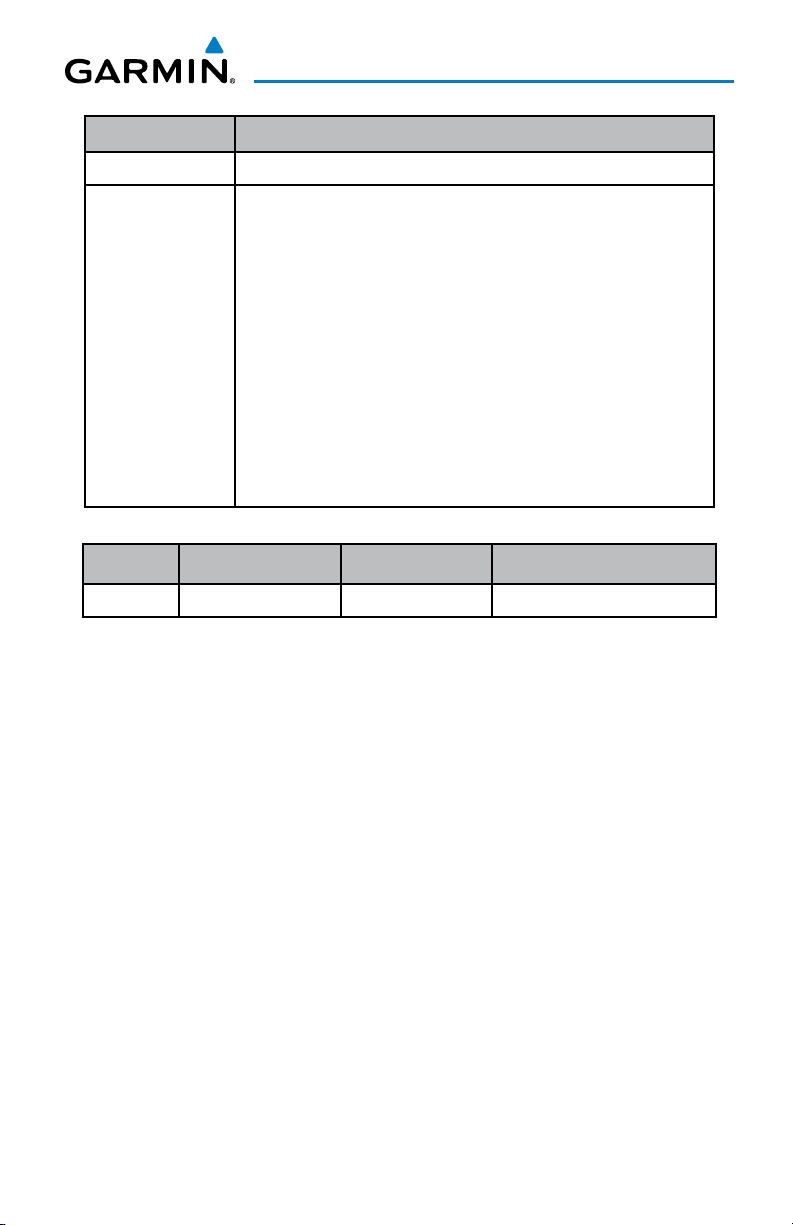
Record of Revisions
Part Number Change Summary
190-01264-00 Initial release
190-01264-01 Updated Flight Instruments section
Renamed GPS Navigation section to FMS Navigation
Updated VNAV discussion in the FMS Navigation section
Added Lightning Detections System to Hazard Avoidance section
Added GFDS Connext Weather to Hazard Avoidance section
Added Electronic Documents to Additional Features section
Added Electronic Checklists to Additional Features section
Added ECS to Additional Features section
Added SMA to Additional Features section
Added Crew Profiles to Additional Features section
Updated PFD softkeys in the Appendix
Added GTC Screen navigation to the Appendix
Revision Date of Revision Affected Pages Description
A May, 2013 All Production release
190-01264-01 Rev. A RR-1
Garmin G2000 Cockpit Reference Guide for the Cessna Corvalis T240
Page 12

Record of Revisions
Blank Page
RR-2
Garmin G2000 Cockpit Reference Guide for the Cessna Corvalis T240
190-01264-01 Rev. A
Page 13

Table of Contents
Flight Instruments ....................................................................................................................... 1
Selecting the Altimeter Barometric Pressure Setting ...................................................... 1
Selecting Standard Barometric Pressure .............................................................................1
Changing Altimeter Barometric Pressure Setting Units .................................................. 1
Setting the Selected Altitude ................................................................................................ 1
Displaying Selected Altitude in Meters ............................................................................... 2
Setting the Baro Transition Alert .......................................................................................... 2
Change Navigation Sources ................................................................................................... 2
Changing the Selected GPS CDI Setting .............................................................................. 2
Changing Navigation Angle Setting ..................................................................................... 3
Enable/Disable OBS Mode While Navigating with FMS ................................................... 3
Adjusting Selected Heading ................................................................................................... 3
Adjusting Selected Course ...................................................................................................... 3
Selecting Bearing Display and Changing Sources ............................................................. 3
Set Barometric Minimum Descent Altitude ........................................................................ 4
Displaying Wind Data .............................................................................................................. 4
Changing Vspeeds and Turning Vspeed Flags On/Off ....................................................... 4
Turning All Vspeed Flags On/Off ............................................................................................ 4
Restoring All Vspeed Defaults ............................................................................................... 5
Enable Split Screen PFD .......................................................................................................... 5
Disable Split Screen PFD ......................................................................................................... 5
Synthetic Vision System .......................................................................................................... 5
Engine Indication System ........................................................................................................ 7
Engine/System Display ............................................................................................................ 8
Fuel Calculations ..................................................................................................................... 10
Engine Lean Assist Mode ...................................................................................................... 11
Nav/Com/Transponder/Audio Panel ................................................................................. 13
Selecting a COM Radio .......................................................................................................... 13
Com Frequency Tuning ........................................................................................................... 14
Changing Com Frequency Channel Spacing ...................................................................... 15
Simultaneous COM Operation ............................................................................................. 16
Selecting a NAV Radio ........................................................................................................... 16
NAV Radio Tuning ................................................................................................................... 16
ADF Tuning (Optional) ............................................................................................................ 17
DME Tuning (Optional) ........................................................................................................... 19
Transponder Operation ......................................................................................................... 19
Intercom .................................................................................................................................... 21
Digital Clearance Player ........................................................................................................ 25
Entertainment Inputs ............................................................................................................. 26
3D Audio ................................................................................................................................... 27
190-01264-01 Rev. A i
Garmin G2000 Cockpit Reference Guide for the Cessna Corvalis T240
Page 14

Table of Contents
Automatic Flight Control System ..................................................................................... 29
Flight Director Activation ..................................................................................................... 29
Vertical Modes .........................................................................................................................30
Lateral Modes .......................................................................................................................... 31
FMS Navigation ........................................................................................................................... 33
Direct-to Navigation .............................................................................................................. 33
Activate a Stored Flight Plan ............................................................................................... 34
Activate a Flight Plan Leg ..................................................................................................... 34
Stop Navigating a Flight Plan .............................................................................................. 35
Vertical Navigation (VNAV)................................................................................................... 35
Flight Planning............................................................................................................................. 41
Weight And Fuel Planning .....................................................................................................41
Trip Planning ............................................................................................................................ 42
Create a User Waypoint ......................................................................................................... 45
Create a Flight Plan ................................................................................................................ 46
Import a Flight Plan from an SD Card ................................................................................ 48
Insert a Waypoint in the Active Flight Plan ...................................................................... 49
Enter an Airway in an Active Flight Plan ........................................................................... 49
Activating Parallel Track ....................................................................................................... 50
User-Defined Holding Patterns ............................................................................................ 50
Invert An Active Flight Plan .................................................................................................. 52
Store a Flight Plan .................................................................................................................. 52
Insert a Waypoint in a Stored Flight Plan ......................................................................... 53
Enter an Airway in a Stored Flight Plan ............................................................................53
Removing Flight Plan Items ................................................................................................. 54
Invert and Activate a Stored Flight Plan ........................................................................... 57
Copy a Stored Flight Plan ..................................................................................................... 57
Delete a Stored Flight Plan .................................................................................................. 57
Export a Flight Plan to an SD Card ..................................................................................... 58
Procedures ..................................................................................................................................... 59
Load and Activate a Departure Procedure ....................................................................... 59
Load An Arrival Procedure .................................................................................................... 60
Load and/or Activate an Approach Procedure ................................................................. 61
Activate An Approach in the Active Flight Plan ............................................................... 63
Activate a Vector to Final Approach Fix ............................................................................ 64
Activate A Missed Approach in the Active Flight Plan ................................................... 64
Temperature Compensated Altitude .................................................................................. 65
ii
Garmin G2000 Cockpit Reference Guide for the Cessna Corvalis T240
190-01264-01 Rev. A
Page 15

Table of Contents
Hazard Avoidance ...................................................................................................................... 67
Customizing the Hazard Displays on the Navigation Map ............................................ 67
Lightning Detection System (Optional) ............................................................................. 70
SiriusXM Weather (Optional) ............................................................................................... 72
Garmin Connext™ Weather (Optional) ............................................................................... 74
Traffic Advisory System ......................................................................................................... 80
Terrain-SVT ............................................................................................................................... 82
Terrain Awareness & Warning System (TAWS) Display (Optional) ............................... 83
Additional Features .................................................................................................................. 87
Terminal Procedure Charts ................................................................................................... 87
Airport Directory .................................................................................................................... 90
SiriusXM Radio Entertainment (Optional) ........................................................................ 90
Text Messaging (SMS) (Optional) ........................................................................................ 93
Scheduled Messages .............................................................................................................. 96
Electronic Stability and Protection ..................................................................................... 98
Electronic Documents (Optional) ........................................................................................ 99
Environmental Control Settings ........................................................................................ 102
Crew Profiles .......................................................................................................................... 103
Electronic Checklists (Optional) ......................................................................................... 105
Abnormal Operation .............................................................................................................. 107
Reversionary Mode .............................................................................................................. 107
Stuck Microphone ................................................................................................................. 107
COM Tuning Failure ...............................................................................................................107
Audio Controller Fail-Safe Operation ..............................................................................108
Hazard Displays with Loss of FMS Position .................................................................... 108
Unusual Attitudes ................................................................................................................. 108
Dead Reckoning .................................................................................................................... 109
Annunciations & Alerts ......................................................................................................... 111
CAS Alerts ............................................................................................................................... 111
Comparator Alerts ................................................................................................................ 113
Reversionary Sensor Alerts ................................................................................................ 114
Message Advisory ................................................................................................................. 114
AFCS Alerts ............................................................................................................................. 115
Terrain-SVT Alerts ................................................................................................................. 116
TAWS Alerts ............................................................................................................................ 117
GDL 69/69A Data Link Receiver Messages ...................................................................... 120
Voice Alerts ............................................................................................................................ 120
GDU 1400W Primary Flight Display & Multi Function Display .................................... 121
Database System Messages ............................................................................................... 123
GIA 63W Integrated Avionics Unit System Messages ................................................... 124
190-01264-01 Rev. A iii
Garmin G2000 Cockpit Reference Guide for the Cessna Corvalis T240
Page 16

Table of Contents
GDC 74A Air Data Computer System Messages ............................................................. 128
GEA 71 Engine/Airframe Unit System Messages ........................................................... 128
GTX 33 Transponder System Messages ............................................................................ 128
GTS 800 Traffic Advisory System Messages .................................................................... 129
GSR 56 Message Advisories ................................................................................................ 129
GMU 44 Magnetometer System Messages ..................................................................... 129
GRS 77 Attitude and Heading Reference System Messages ....................................... 130
GTC 570 Touchscreen Controller System Messages ...................................................... 132
GCU 275 PFD Controller System Messages ..................................................................... 132
GDL 69/69A Satellite Datalink Receiver System Messages ......................................... 133
GMA 36 Remote Audio Controller System Messages ................................................... 133
GMC 720 AFCS Controller System Messages .................................................................. 134
Miscellaneous System Messages ...................................................................................... 134
Flight Plan Import/Export Messages ................................................................................ 139
Crew Profile Import/Export Messages ............................................................................. 140
Appendix ....................................................................................................................................... 143
PFD Softkeys .......................................................................................................................... 143
GTC Screens ............................................................................................................................ 149
Database Management ....................................................................................................... 161
Automatic Database Synchronization Feature .............................................................. 165
Garmin Databases ................................................................................................................ 168
Magnetic Field Variation Database Update .................................................................... 170
Cleaning the Touchscreen ................................................................................................... 172
Index ...........................................................................................................................................Index-1
iv
Garmin G2000 Cockpit Reference Guide for the Cessna Corvalis T240
190-01264-01 Rev. A
Page 17

Flight Instruments
FLIGHT INSTRUMENTS
SELECTING THE ALTIMETER BAROMETRIC PRESSURE SETTING
Turn the BARO Knob on the PFD Controller to select the desired setting.
SELECTING STANDARD BAROMETRIC PRESSURE
Press the BARO Knob on the GDU Controller to select standard pressure;
STD BARO is displayed in the Barometric Setting box.
CHANGING ALTIMETER BAROMETRIC PRESSURE SETTING UNITS
1)
Press the PFD Settings Softkey on the PFD to display the second-level
softkeys.
2)
Press the Other PFD Settings Softkey.
3)
Press the Altitude Units Softkey.
4)
Press the IN Softkey to display the barometric pressure setting in inches of
mercury (in Hg).
Or
, press the HPA Softkey to display the barometric pressure setting in
hectopascals (hPa).
5)
Press the Back Softkey to return to the previous level of softkeys.
Instruments EIS
Flight
XPDR/Audio AFCS FMS Nav
Nav/Com/
Planning Procedures
Flight
Avoidance
Hazard
SETTING THE SELECTED ALTITUDE
Turn the ALT Knob on the AFCS Controller to set the Selected Altitude in
100-ft increments. When meters are displayed, Selected Altitude is adjusted
in 50 meter increments..
If set, the Minimum Descent Altitude/Decision Height (MDA/DH) value is
also available for the Selected Altitude.
190-01264-01 Rev. A 1
Garmin G2000 Cockpit Reference Guide for the Cessna Corvalis T240
Additional
Features
Operation
Abnormal
Annun/
Alerts Appendix Index
Page 18

Flight Instruments
DISPLAYING SELECTED ALTITUDE IN METERS
Flight
1)
InstrumentsEIS
Press the PFD Settings Softkey on the PFD to display the second-level
softkeys.
2)
Press the Other PFD Settings Softkey.
3)
Press the Altitude Units Softkey.
4)
Press the Meters Softkey to turn on metric altitude readouts.
Nav/Com/
XPDR/AudioAFCSFMS Nav
5)
Press the Back Softkey to return to the previous level of softkeys.
SETTING THE BARO TRANSITION ALERT
1)
From the Home Screen on the Touchscreen Controller, touch Utilities >
Setup > Avionics Settings.
2)
Touch the Alerts Tab.
•
To turn the alert on or off, touch the Baro Transition Alert Enable
Flight
PlanningProcedures
Hazard
CHANGE NAVIGATION SOURCES
Avoidance
Button. An illuminated green line below “Enable” indicates that the alert is
on.
•
To set or change the Baro Transition Alert Altitude, touch the Baro
Transition Alert Data Field. Enter the desired altitude on the keypad, and
touch Enter.
1)
Press the Active Nav Softkey on the PFD to change from FMS to VOR1 or
Features
Additional
LOC1.
2)
Press the Active Nav Softkey again to change from VOR1 or LOC1 to
VOR2 or LOC2.
Abnormal
Operation
3)
Press the Active Nav Softkey a third time to return to FMS.
CHANGING THE SELECTED GPS CDI SETTING
AlertsAppendixIndex
Annun/
1)
From the Home Screen on the Touchscreen Controller, touch Utilities >
Setup > Avionics Settings.
2)
Touch the System Tab.
3)
Touch the GPS CDI Data Field.
4)
Touch desired setting (2.00 NM, 1.00 NM, 0.30 NM, or AUTO).
2
Garmin G2000 Cockpit Reference Guide for the Cessna Corvalis T240
190-01264-01 Rev. A
Page 19

Flight Instruments
CHANGING NAVIGATION ANGLE SETTING
1)
From the Home Screen on the Touchscreen Controller, touch Utilities >
Setup > Avionics Settings.
2)
Touch the Units Tab.
3)
Touch the Nav Angle Data Field.
4)
Touch the desired setting (Magnetic or True).
ENABLE/DISABLE OBS MODE WHILE NAVIGATING WITH FMS
1)
Press the OBS Softkey on the PFD to select OBS Mode.
2)
Turn the CRS Knob on the AFCS Controller to select the desired course to/
from the waypoint. Press the CRS Knob to synchronize the Selected Course
with the bearing to the next waypoint.
3)
Press the OBS Softkey again to return to automatic waypoint sequencing.
ADJUSTING SELECTED HEADING
Turn the HDG Knob on the AFCS Controller to set the selected heading.
Press the HDG Knob to synchronize the bug to the current heading.
ADJUSTING SELECTED COURSE
Instruments EIS
Flight
XPDR/Audio AFCS FMS Nav
Nav/Com/
Planning Procedures
Flight
Avoidance
Hazard
Turn the CRS Knob on the AFCS Controller to set the Selected Course.
Press the CRS Knob to re-center the CDI and return the course pointer to
the bearing of the active waypoint or navigation station (see OBS Mode for
adjusting an FMS course).
SELECTING BEARING DISPLAY AND CHANGING SOURCES
1)
Press the PFD Settings Softkey on the PFD.
2)
Press a bearing softkey (Bearing 1 or Bearing 2) to display the desired
bearing pointer and information window with a NAV source.
3)
Press the bearing softkey again to change the bearing source to FMS.
4)
To remove the bearing pointer and information window, press the bearing
softkey again.
190-01264-01 Rev. A 3
Garmin G2000 Cockpit Reference Guide for the Cessna Corvalis T240
Additional
Features
Operation
Abnormal
Annun/
Alerts Appendix Index
Page 20
Flight Instruments
SET BAROMETRIC MINIMUM DESCENT ALTITUDE
Flight
1)
InstrumentsEIS
From the Home Screen on the Touchscreen Controller, touch Utilities >
Minimums.
2)
Touch Baro, or Temp Comp (use the keypad to enter the desired
temperature for temperature compensated VNAV) (OFF is selected by
default). To remove the window from the PFD display, touch OFF.
3)
Nav/Com/
XPDR/AudioAFCSFMS Nav
Use the keypad to enter the desired altitude (from zero to 16,000 feet for
Baro), and touch Enter.
DISPLAYING WIND DATA
1)
Press the PFD Settings Softkey on the PFD.
2)
Press the Other PFD Settings Softkey.
3)
Press the Wind Softkey to display wind data display options.
4)
Flight
PlanningProcedures
Press one of the option softkeys (Option 1, Option 2, or Option 3) to
change how wind data is displayed.
5)
To remove the window, press the Off Softkey.
CHANGING VSPEEDS AND TURNING VSPEED FLAGS ON/OFF
1)
Hazard
Avoidance
From the Home Screen on the Touchscreen Controller, touch Speed Bugs
2)
To turn the Vspeed on or off, touch the On Button . The illuminated green
line below “On” indicates that the Vspeed flag is on.
Features
Additional
3)
To set or change a Vspeed value, touch the Data Field for the Vspeed, enter
a value in the keypad, and touch
Enter.
The pencil icon next to the Vspeed
value indicates that the Vspeed is a pilot-entered value.
Abnormal
Operation
TURNING ALL VSPEED FLAGS ON/OFF
AlertsAppendixIndex
Annun/
1)
From the Home Screen on the Touchscreen Controller, touch Utilities >
Speed Bugs.
2)
To activate all Vspeed flags, touch the All Bugs On Button.
3)
To remove all Vspeed flags, touch the All Bugs Off Button.
4
Garmin G2000 Cockpit Reference Guide for the Cessna Corvalis T240
190-01264-01 Rev. A
Page 21

Flight Instruments
RESTORING ALL VSPEED DEFAULTS
1)
From the Home Screen on the Touchscreen Controller, touch Utilities >
Speed Bugs.
2)
Touch the Restore All Defaults Button.
ENABLE SPLIT SCREEN PFD
1)
Press the PFD Settings Softkey on the PFD.
2)
Press the PFD Mode Softkey. Split is now annunciated on the softkey
label and the multi-function pane is displayed to the right of the Primary
Flight Display.
DISABLE SPLIT SCREEN PFD
1)
Press the PFD Settings Softkey on the PFD.
2)
Press the PFD Mode Softkey. FULL is now annunciated on the softkey
label and the multi-function pane is no longer displayed.
SYNTHETIC VISION SYSTEM
WARNING: Use appropriate primary systems for navigation, and for terrain
and obstacle avoidance. SVT is intended as an aid to situational awareness only
and may not provide either the accuracy or reliability upon which to solely base
decisions and/or plan maneuvers to avoid terrain, obstacles, or traffic.
Instruments EIS
Flight
XPDR/Audio AFCS FMS Nav
Nav/Com/
Planning Procedures
Flight
Avoidance
Hazard
Additional
Features
WARNING: Do not use SVT runway depiction as the sole means for determining
the proximity of the aircraft to the runway or for maintaining the proper approach
path angle during landing.
Garmin SVT™ (Synthetic Vision Technology) functionality is offered as an
enhancement to the G2000 system.
SVT is primarily comprised of a computer-generated forward-looking, attitude
aligned view of the topography immediately in front of the aircraft from the pilot’s
perspective. SVT information is shown on the primary flight display (PFD).
In addition to SVT enhancement to the PFD, the following features have been
added to the PFD:
190-01264-01 Rev. A 5
Garmin G2000 Cockpit Reference Guide for the Cessna Corvalis T240
Operation
Abnormal
Annun/
Alerts Appendix Index
Page 22
Flight Instruments
• Flight Path Marker
Flight
• Horizon Heading Marks
InstrumentsEIS
• Terrain and Obstacle Alerting
• Three-dimensional Traffic
• Airport Signs
• Runway Display
Activating and deactivating SVT:
Nav/Com/
XPDR/AudioAFCSFMS Nav
Press the PFD Settings Softkey > Attitude Overlays Softkey >
Synthetic Terrain Softkey. The SVT display will cycle on or off with each
press of the Synthetic Terrain Softkey.
NOTE: Pathways, Horizon Headings and Airport Signs are only available if
Synthetic Terrain is active.
Activating and deactivating Pathways:
Flight
PlanningProcedures
Press the PFD Settings Softkey > Attitude Overlays Softkey >
Pathways Softkey. Pathways will cycle on or off with each press of the
Pathways Softkey.
Activating and deactivating Horizon Headings:
Press the PFD Settings Softkey > Attitude Overlays Softkey > Horizon
Hazard
Avoidance
Heading Softkey. The Horizon Heading display will cycle on or off with
each press of the Horizon Heading Softkey.
Features
Additional
Abnormal
Operation
AlertsAppendixIndex
Annun/
Activating and deactivating Airport Signs:
Press the PFD Settings Softkey > Attitude Overlays Softkey > Airport
Signs Softkey. Airport Signs will cycle on or off with each press of the
Airport Signs Softkey.
6
Garmin G2000 Cockpit Reference Guide for the Cessna Corvalis T240
190-01264-01 Rev. A
Page 23
Engine Indication System
ENGINE INDICATION SYSTEM
Instruments EIS
Flight
1
2
3
4
5
6
Selected Tank
7
8
10
11
12
13
14
15
16
9
XPDR/Audio AFCS FMS Nav
Nav/Com/
Planning Procedures
Flight
Avoidance
Hazard
Additional
Features
Operation
Abnormal
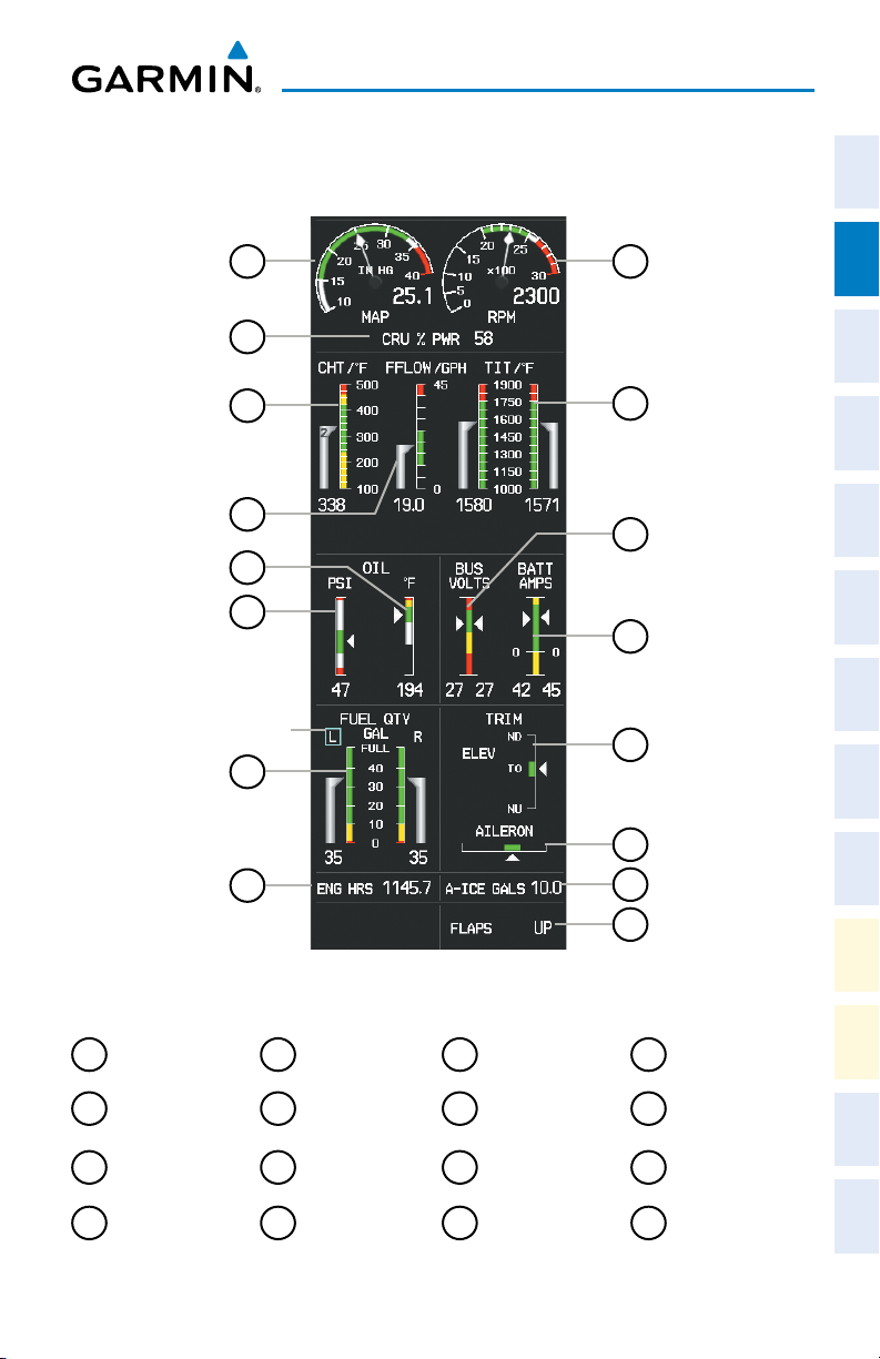
EIS Display (Normal Mode)
Manifold Pressure
1
Cruise Power
2
Display
Cylinder Head
3
Temperature
Fuel Flow
4
190-01264-01 Rev. A 7
Oil Temperature
5
Oil Pressure
6
Fuel Quantity
7
Engine Hours
8
Display
Garmin G2000 Cockpit Reference Guide for the Cessna Corvalis T240
Tachometer
9
Turbo Inlet
10
Temperature
Dual Voltmeter
11
Dual Ammeter
12
Elevator Trim
13
Aileron Trim
14
Anti-Ice Fluid
15
Quantity (Optional)
Flaps Position
16
Indicator
Alerts Appendix Index
Annun/
Page 24
Engine Indication System
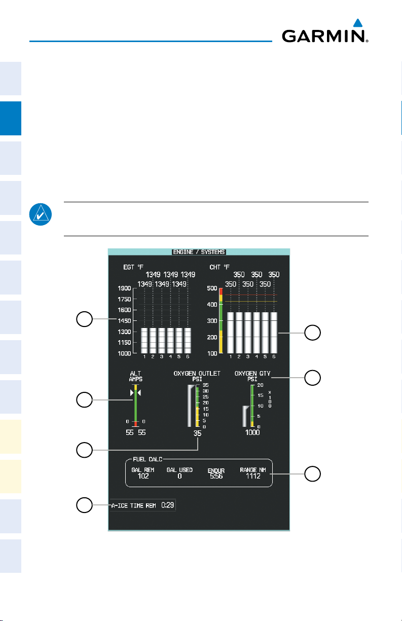
ENGINE/SYSTEM DISPLAY
Flight
The Engine/Systems Display shows engine, electrical, oxygen, and fuel calculation
InstrumentsEIS
information using bar graphs, digital readouts, and slide bars on the selected Display
Pane.
Accessing the Engine/Systems Display:
Nav/Com/
XPDR/AudioAFCSFMS Nav
From the Home Screen on the Touchscreen Controller, touch Aircraft
Systems > Engine/Sys.
NOTE: The Engine/Systems display is shown in Half Mode, and is not available
in Full Mode or Reversionary Mode.
Flight
PlanningProcedures
1
5
Hazard
Avoidance
Features
Additional
Abnormal
Operation
AlertsAppendixIndex
Annun/
6
2
3
7
4
Engine and Systems Display
8
Garmin G2000 Cockpit Reference Guide for the Cessna Corvalis T240
190-01264-01 Rev. A
Page 25
Engine Indication System
1
Exhaust Gas Temperature
(EGT °F)
For each cylinder, the exhaust gas temperatures
are shown in degrees Fahrenheit (°F). Each bar
segment on the graph represents 25 degrees.
2
Alternator Amps
(ALT AMPS)
Currents for the right and left alternators are
displayed using vertical bar indicators and
readouts
3
Oxygen Outlet Pressure Gauge
(OXY OUTLET PSI)
Oxygen outlet pressure in psi. Gauge ranges
are dependent on the oxygen outlet pressure
system.
4
Anti-ice Time Remaining
(A-ICE TIME REM)
5
Oxygen Quantity Gauge
(OXY QTY PSI)
6
Cylinder Head Temperature
(CHT °F)
Anti-ice time remaining based on the remaining
fluid quantity. (Optional).
Oxygen amount in psi; note that gauge
increment is 100 psi.
For each cylinder, the head temperatures are
shown in degrees Fahrenheit (°F). Each bar
segment on the graph represents 100 degrees.
7
Fuel Calculations Group
(GAL REM, GAL USED,
ENDUR, RANGE NM)
The fuel totalizer fuel remaining and used
and the totalizer-based endurance and range
calculations are displayed
Enabling/Disabling the Oxygen System:
1)
From the Home Screen on the Touchscreen Controller, touch Aircraft
Systems.
2)
Touch the Oxygen Button. When the button annunciator is green, oxygen
is enabled, annunciator is gray when disabled.
Instruments EIS
Flight
XPDR/Audio AFCS FMS Nav
Nav/Com/
Planning Procedures
Flight
Avoidance
Hazard
Additional
Features
Operation
Abnormal
190-01264-01 Rev. A 9
Garmin G2000 Cockpit Reference Guide for the Cessna Corvalis T240
Alerts Appendix Index
Annun/
Page 26
Engine Indication System
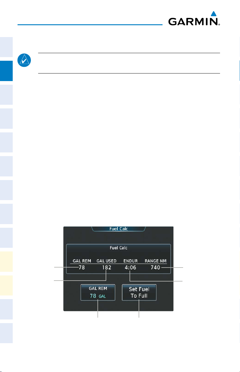
FUEL CALCULATIONS
Flight
InstrumentsEIS
NOTE: Fuel calculations do not use the aircraft fuel quantity indicators and
are calculated from the last time the fuel totalizer quantity was reset.
The system calculates Fuel used (GAL USED), endurance (ENDUR), and range
(RANGE NM) based on the displayed fuel remaining (GAL REM), fuel flow, and
groundspeed.
Nav/Com/
XPDR/AudioAFCSFMS Nav
Adjusting the Totalizer-Based Fuel Remaining:
1)
From the Home Screen on the Touchscreen Controller, touch Aircraft
Systems > Fuel Calc.
2)
Touch the Gal Rem Button.
3)
Enter the fuel quantity using the numeric keypad or large and small right
knobs, then touch the Enter Button. The totalizer-based fuel remaining is
Flight
PlanningProcedures
set to the entered fuel quantity and the GAL USED is set to zero.
Setting the Totalizer-Based Fuel Remaining to Full Fuel:
1)
From the Home Screen on the Touchscreen Controller, touch Aircraft
Systems > Fuel Calc.
2)
Touch the Set To Full Fuel Button. The totalizer-based fuel remaining is
Hazard
Avoidance
set to the aircraft’s usable fuel capacity and the GAL USED is set to zero.
Features
Additional
Abnormal
Operation
AlertsAppendixIndex
Annun/
10
Fuel
Remaining
Fuel Used
Calculation
Edit Remaining Fuel
Quantity
Set Fuel Quantity
to Full
Fuel Calculations Screen
Garmin G2000 Cockpit Reference Guide for the Cessna Corvalis T240
Range
Calculation
Endurance
Calculation
190-01264-01 Rev. A
Page 27
Engine Indication System
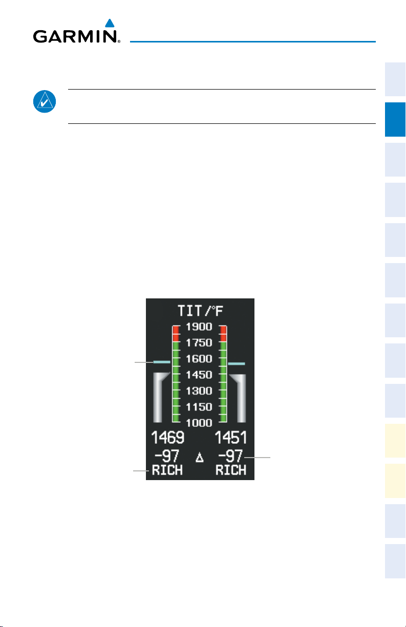
ENGINE LEAN ASSIST MODE
Instruments EIS
Flight
NOTE: Consult the Cessna Corvalis T240 Aircraft Flight Manual (AFM) for
leaning procedures.
While the Lean Assist Mode is active, the system indicates the peak of each TIT on
XPDR/Audio AFCS FMS Nav
Nav/Com/
the EIS display with a light blue bar which remains at the peak Turbo Inlet Temperature.
Readouts below each TIT gauge indicate the difference between each peak TIT and
the current temperature. An indicator below the readout shows whether each TIT is
operating ‘LEAN’ or ‘RICH’ of peak TIT.
Enabling/Disabling Lean Assist Mode:
1)
From the Home Screen on the Touchscreen Controller, touch Aircraft
Systems.
2)
Touch the Lean Assist Button. The button annunciator is green when Lean
Planning Procedures
Flight
Assist Mode is enabled, annunciator is gray when disabled.
Avoidance
Hazard
Peak TIT
TIT Deviation
Lean or Rich
from Peak
from Peak
Engine Lean Assist Mode (EIS Display)
190-01264-01 Rev. A 11
Garmin G2000 Cockpit Reference Guide for the Cessna Corvalis T240
Additional
Features
Operation
Abnormal
Annun/
Alerts Appendix Index
Page 28
Engine Indication System
Flight
InstrumentsEIS
Nav/Com/
XPDR/AudioAFCSFMS Nav
Flight
PlanningProcedures
Blank Page
Hazard
Avoidance
Features
Additional
Abnormal
Operation
AlertsAppendixIndex
Annun/
12
Garmin G2000 Cockpit Reference Guide for the Cessna Corvalis T240
190-01264-01 Rev. A
Page 29
Nav/Com/XPDR/Audio Panel
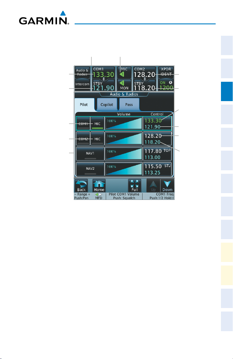
NAV/COM/TRANSPONDER/AUDIO PANEL
CNS Bar MIC Button (COM1 selected for transmission)
Instruments EIS
Flight
COM1 Active Frequency
(selected for transmission)
COM1 Standby
Frequency
MIC Button
(COM1 selected for
transmission)
MIC Button(COM2)
Audio & Radios Screen
Selecting a COM Radio for Transmission
SELECTING A COM RADIO
Selecting a COM Radio for transmission:
Touch the MIC Button in the CNS Bar on the Touchscreen Controller to
switch between COM radios until the desired COM is selected.
Or:
1)
Touch the Audio & Radios Button to display the Audio & Radios Screen.
2)
If necessary, touch the Copilot Tab.
3)
If necessary, touch the Sync to Pilot Button to disable synchronizing
selections to the pilot.
4)
Touch the desired MIC Button on the Audio & Radios Screen to select the
COM radio for transmission.
Or:
COM2 Primary
Frequency
COM2 Standby
Frequency
COM1 Active
Frequency
COM1 Standby
Frequency
COM2 Primary
Frequency
COM2 Standby
Frequency
XPDR/Audio AFCS FMS Nav
Nav/Com/
Planning Procedures
Flight
Avoidance
Hazard
Additional
Features
Operation
Abnormal
Annun/
Alerts Appendix Index
190-01264-01 Rev. A 13
Garmin G2000 Cockpit Reference Guide for the Cessna Corvalis T240
Page 30

Nav/Com/XPDR/Audio Panel
1)
On the PFD Controller, press the COM/NAV Button to display the COM/
Flight
InstrumentsEIS
NAV Window on the PFD.
2)
Turn the large PFD Knob to move the cursor to the MIC field.
3)
Turn the small PFD Knob to select the desired COM.
4)
Press the COM/NAV Button to hide the COM/NAV Window.
Selecting a COM Radio for monitoring:
Nav/Com/
XPDR/AudioAFCSFMS Nav
Touch the MON Button in the CNS Bar on the Touchscreen Controller to
monitor the COM not selected for transmission.
Or:
1)
Touch the Audio & Radios Button to display the Audio & Radios Screen.
2)
If necessary, touch the Copilot Tab.
3)
If necessary, touch the Sync to Pilot Button to disable synchronizing
selections to the pilot.
4)
Flight
PlanningProcedures
Touch the COM1 Button or COM2 Button to select the COM1/COM2 radio
for monitoring.
COM FREQUENCY TUNING
Hazard
Avoidance
Features
Additional
Abnormal
Operation
AlertsAppendixIndex
Annun/
Selecting a COM frequency using the Touchscreen Controller:
1)
Touch the COM1 STBY Button or COM2 STBY Button in the CNS Bar on
the Touchscreen Controller to display the COM1/COM2 Standby Screen.
2)
Use the keypad to select the frequency.
3)
Touch the Enter Button to accept the new frequency as the COM1/COM2
standby frequency; or touch the XFER Button to accept the new frequency
as the COM1/COM2 active frequency and transfer the previously active
frequency to the standby frequency.
Or:
1)
Touch the Audio & Radios Button to display the Audio & Radios Screen.
2)
Touch the COM1/COM2 frequency button to display the COM1/COM2
Standby Screen.
3)
Use the keypad to select the desired frequency.
4)
Touch the Enter Button to accept the new frequency as the COM1/COM2
standby frequency; or touch the XFER Button to accept the new frequency
as the COM1/COM2 active frequency and transfer the previously active
frequency to the standby frequency.
14
Garmin G2000 Cockpit Reference Guide for the Cessna Corvalis T240
190-01264-01 Rev. A
Page 31

Nav/Com/XPDR/Audio Panel
Or:
1)
Press the small right knob to select the COM desired for tuning (selected
standby frequency is light blue).
2)
Turn the large and small right knobs to tune the frequency (Large knob
increases/decreases MHz; Small knob increases/decreases kHz).
3)
Press the small right knob to enter the new frequency as the standby
frequency; or press and hold the small right knob to transfer the new
standby frequency to the active frequency.
Selecting a COM frequency using the PFD Controller:
1)
On the PFD Controller, press the COM/NAV Button to display the COM/
NAV Window on the PFD.
2)
Turn the large PFD Knob to move the cursor to the SOURCE field.
3)
Turn either PFD Knob to select the desired COM.
4)
Press the ENT Key or the small PFD Knob to accept the selection and move
the cursor to the STBY frequency field.
5)
Turn the small PFD Knob one click to activate the editing cursor (flashing).
6)
Turn the large and small PFD knobs to select the frequency (Large knob
increases/decreases MHz; Small knob increases/decreases kHz)
7)
Press the ENT Key or the small PFD Knob to accept the selection and move
the cursor to the XFER? field.
8)
Press the ENT Key or the small PFD Knob to accept the new frequency
as the COM1/COM2 active frequency and transfer the previously active
frequency to the standby frequency.
CHANGING COM FREQUENCY CHANNEL SPACING
Instruments EIS
Flight
XPDR/Audio AFCS FMS Nav
Nav/Com/
Planning Procedures
Flight
Avoidance
Hazard
Additional
Features
Operation
Abnormal
Changing COM frequency channel spacing:
1)
From the Home Screen on the Touchscreen Controller , touch Utilities >
Setup > Avionics Settings.
2)
Touch the Systems Tab (if necessary). Scroll the list to show the COM
Channel Spacing button.
3)
Touch the COM Channel Spacing button to display the choice of 25.0 kHz
or 8.33 kHz.
190-01264-01 Rev. A 15
Garmin G2000 Cockpit Reference Guide for the Cessna Corvalis T240
Alerts Appendix Index
Annun/
Page 32

Nav/Com/XPDR/Audio Panel
SIMULTANEOUS COM OPERATION
Flight
1)
InstrumentsEIS
Touch the Audio & Radios Button on the Touchscreen Controller to
display the Audio & Radios Screen.
2)
Touch the Copilot Tab.
3)
Touch the Sync to Pilot Button to disable/enable synchronizing the copilot
COM selections to the pilot.
4)
Nav/Com/
XPDR/AudioAFCSFMS Nav
Touch the COM1/COM2 MIC Button to select COM1/COM2 for copilot
transmissions.
SELECTING A NAV RADIO
1)
Touch the Audio & Radios Button on the Touchscreen Controller to
display the Audio & Radios Screen.
2)
If necessary, touch the Copilot Tab.
3)
Flight
PlanningProcedures
If necessary, touch the Sync to Pilot Button to disable synchronizing
selections to the pilot.
4)
Touch the NAV1 or NAV2 Button on the Audio & Radios Screen to select/
deselect the radio for monitoring.
NAV RADIO TUNING
Hazard
Additional
Abnormal
Annun/
Selecting a NAV frequency using the Touchscreen Controller:
Avoidance
1)
Touch the Audio & Radios Button on the Touchscreen Controller to
display the Audio & Radios Screen.
Features
2)
Touch the NAV1/NAV2 frequency button to select NAV1/NAV2 for tuning,
and display the NAV1/NAV2 frequency tuning screen.
3)
Operation
Use the keypad to select the desired frequency.
4)
Touch the Enter Button to enter the new frequency as the NAV1/NAV2
standby frequency; or touch the XFER Button to enter the new frequency as
AlertsAppendixIndex
the NAV1/NAV2 standby frequency and transfer it to the active frequency.
Or:
1)
Touch the Audio & Radios Button to display the Audio & Radios Screen.
2)
Touch the NAV1/NAV2 volume slider to select NAV1/NAV2 for tuning.
3)
Turn the large and small right knobs to tune the frequency (Large knob
increases/decreases MHz; Small knob increases/decreases kHz).
16
Garmin G2000 Cockpit Reference Guide for the Cessna Corvalis T240
190-01264-01 Rev. A
Page 33

Nav/Com/XPDR/Audio Panel
4)
Press the small right knob to enter the new frequency as the NAV1/NAV2
standby frequency; or press and hold the small right knob to transfer the
new standby frequency to the active frequency.
Selecting a NAV frequency using the PFD Controller:
1)
On the PFD Controller, press the COM/NAV Button to display the COM/
NAV Window.
2)
Turn the large PFD Knob to move the cursor to the SOURCE field.
3)
Turn either PFD Knob to select the desired NAV.
4)
Press the ENT Key or the small PFD Knob to accept the selection and move
the cursor to the STBY frequency field.
5)
Turn the small PFD Knob one click to activate the editing cursor (flashing).
6)
Turn the large and small PFD knobs to tune the frequency (Large knob
increases/decreases MHz; Small knob increases/decreases kHz).
7)
Press the ENT Key or the small PFD Knob to accept the selection and move
the cursor to the XFER? field.
8)
Press the ENT Key or the small PFD Knob to transfer the standby frequency
to the active frequency.
ADF TUNING (OPTIONAL)
Selecting an ADF frequency:
1)
Touch the Audio & Radios Button on the Touchscreen Controller to
display the Audio & Radios Screen.
2)
Scroll the list to find the ADF enable/disable button.
3)
Touch the ADF control button to display the ADF Mode/Tuning Screen.
4)
Use the keypad to select the desired frequency.
5)
Touch the Enter Button to enter the new frequency as the ADF standby
frequency; or touch the XFER Button to enter the new frequency as the
ADF standby frequency and transfer it to the active frequency.
Or:
1)
Touch the Audio & Radios Button to display the Audio & Radios Screen.
2)
Scroll the list to find the ADF.
3)
Touch the ADF control button to display the ADF Mode/Tuning Screen.
Instruments EIS
Flight
XPDR/Audio AFCS FMS Nav
Nav/Com/
Planning Procedures
Flight
Avoidance
Hazard
Additional
Features
Operation
Abnormal
Annun/
Alerts Appendix Index
190-01264-01 Rev. A 17
Garmin G2000 Cockpit Reference Guide for the Cessna Corvalis T240
Page 34

Nav/Com/XPDR/Audio Panel
4)
Turn the large and small right knobs to tune the frequency (Large knob
Flight
InstrumentsEIS
increases/decreases kHz; Small knob selects .5 kHz).
5)
Press the small right knob to enter the new frequency as the ADF standby
frequency; or press and hold the small right knob to transfer the new
standby frequency to the active frequency.
Finding and selecting an ADF frequency:
1)
Nav/Com/
XPDR/AudioAFCSFMS Nav
Touch the Audio & Radios Button on the Touchscreen Controller to
display the Audio & Radios Screen.
2)
Scroll the list to find the ADF.
3)
Touch the ADF control button to display the ADF Mode/Tuning Screen.
4)
Touch the Find Button.
5)
Touch the tab for the desired type of frequency (Recent, Nearest, Dest,
Flight Plan, or Favorite).
6)
Scroll the list to find the desired frequency.
Flight
PlanningProcedures
7)
Touch the frequency button to enter the new frequency as the ADF standby
frequency.
Selecting an ADF receiver mode:
1)
Touch the Audio & Radios Button on the Touchscreen Controller to
display the Audio & Radios Screen.
Hazard
Avoidance
2)
Scroll the list to find the ADF.
3)
Touch the ADF control button to display the ADF Mode/Tuning Screen.
4)
Features
Additional
Touch the ANT, ADF, ADF/BFO, or ANT/BFO Button to select the ADF
mode.
Abnormal
Operation
AlertsAppendixIndex
Annun/
Transferring the active and standby ADF frequencies:
1)
Touch the Audio & Radios Button on the Touchscreen Controller to
display the Audio & Radios Screen.
2)
Scroll the list to find the ADF.
3)
Touch the ADF control button.
4)
Touch the XFER Button
Or
1)
Touch the Audio & Radios Button on the Touchscreen Controller to
display the Audio & Radios Screen.
18
Garmin G2000 Cockpit Reference Guide for the Cessna Corvalis T240
190-01264-01 Rev. A
Page 35

Nav/Com/XPDR/Audio Panel
2)
Scroll the list to find the ADF.
3)
Touch the ADF volume slider to select the ADF for transfer.
4)
Press and hold the small right knob to transfer the frequencies.
DME TUNING (OPTIONAL)
1)
Touch the Audio & Radios Button on the Touchscreen Controller to
display the Audio & Radios Screen.
2)
Scroll the list to find the DME.
3)
Touch the DME mode control button to display the DME Mode Window.
4)
Touch the NAV1 Mode, NAV2 Mode, or HOLD Mode Button to select
the DME mode.
TRANSPONDER OPERATION
Enter a Transponder Code
Transponder Display and Controls
XPDR IDENT Button
Transponder Mode Button
Instruments EIS
Flight
XPDR/Audio AFCS FMS Nav
Nav/Com/
Planning Procedures
Flight
Avoidance
Hazard
1)
Touch the Transponder Mode Button on the Touchscreen Controller to
display the Transponder Screen.
2)
Use the keypad to select the desired code.
3)
Touch the Enter Button to enter the new code.
Or:
1)
Touch the Transponder Mode Button to display the Transponder Screen.
2)
Turn the small right knob one click either way to erase the previous code
and place the editing cursor on the first digit.
3)
Turn the small right knob to enter the first digit.
4)
Turn the large right knob to move the cursor to the next digit.
5)
Turn the small right knob to enter the next digit, repeat steps 4 and 5 until
complete.
6)
Touch the Enter Button, or push the small right knob, to enter the new
code.
190-01264-01 Rev. A 19
Garmin G2000 Cockpit Reference Guide for the Cessna Corvalis T240
Additional
Features
Operation
Abnormal
Annun/
Alerts Appendix Index
Page 36

Nav/Com/XPDR/Audio Panel
Selecting a Transponder Mode:
Flight
Nav/Com/
InstrumentsEIS
XPDR/AudioAFCSFMS Nav
1)
Touch the Transponder Mode Button to display the Transponder Screen.
2)
Touch a Mode Button to activate the transponder mode.
Transponder
Mode Buttons
Flight
PlanningProcedures
Transponder Mode Selection
Transponder Mode Description
Hazard
Avoidance
Altitude Reporting
(ALT)
Features
Additional
On
Abnormal
Operation
Ground (GND)
AlertsAppendixIndex
Annun/
Altitude Reporting Mode is automatically selected when the aircraft
becomes airborne. Altitude Reporting Mode may also be selected
manually by selecting the
Altitude Reporting
ON Mode can be selected at any time by selecting the ON Button. ON
Mode generates Mode A and Mode S replies (ADSB-OUT), but Mode C
altitude reporting is inhibited.
Ground Mode is normally selected automatically when the aircraft is on
the ground. In Ground Mode, the transponder does not allow Mode A
and Mode C replies, but it does permit acquisition squitter and replies
to discretely addressed Mode S interrogations (ADSB-OUT).
Button. (ADSB-OUT)
Standby (STBY)
FLIGHT ID
20
Garmin G2000 Cockpit Reference Guide for the Cessna Corvalis T240
Standby Mode can be selected at any time by selecting the
Standby
Button. In Standby, the transponder does not reply to interrogations,
but new codes can be entered (NO ADSB-OUT).
The Mode S Transponder reports aircraft identification as the aircraft
registration number. The Flight ID cannot be changed by the pilot.
190-01264-01 Rev. A
Page 37

Nav/Com/XPDR/Audio Panel
INTERCOM
Touch the Link Arrow to enable (green) or disable (gray) a link.
Intercom Button
Pilot/Copilot Link Arrow
Pilot Volume Button
Pilot/Passenger Link Arrow
Intercom Controls
Copilot Volume
Button
Copilot/Passenger
Link Arrow
Passenger Volume
Button
Instruments EIS
Flight
XPDR/Audio AFCS FMS Nav
Nav/Com/
Planning Procedures
Flight
Avoidance
Hazard
NOTE: In the default ICS configuration, only the pilot and copilot positions
can hear aircraft alerts.
All Intercom Mode
Additional
Features
Operation
Abnormal
In ‘All Intercom’ mode the Pilot, Copilot, and Passengers hear each other and hear
the aircraft audio.
Annun/
Alerts Appendix Index
All Intercom Mode
190-01264-01 Rev. A 21
Garmin G2000 Cockpit Reference Guide for the Cessna Corvalis T240
Page 38

Nav/Com/XPDR/Audio Panel
Copilot-Passenger Intercom Mode
Flight
Nav/Com/
In ‘Copilot-Passenger’ mode the Pilot, Copilot, and Passengers hear the aircraft
InstrumentsEIS
audio. The Copilot and Passengers also hear each other.
XPDR/AudioAFCSFMS Nav
Copilot-Passenger Intercom Mode
Pilot-Copilot Intercom Mode
Flight
PlanningProcedures
In ‘Pilot-Copilot’ mode the Pilot and Copilot hear the aircraft audio and each other.
The Passengers hear each other.
Hazard
Avoidance
Features
Additional
Abnormal
Operation
AlertsAppendixIndex
Annun/
22
Pilot-Copilot Intercom Mode
Garmin G2000 Cockpit Reference Guide for the Cessna Corvalis T240
190-01264-01 Rev. A
Page 39

Nav/Com/XPDR/Audio Panel
Pilot-Passenger Intercom Mode
Instruments EIS
Flight
In ‘Pilot-Passenger’ mode the Pilot, Copilot, and Passengers hear the aircraft audio.
The Pilot and Passengers also hear each other. The Copilot has the option to use SplitCOM mode.
XPDR/Audio AFCS FMS Nav
Nav/Com/
Pilot-Passenger Intercom Mode
Planning Procedures
Flight
All Isolate Mode
In ‘All Isolate’ mode the Pilot and Copilot hear the aircraft audio. The Copilot has
the option to use Split-COM mode. The Passengers hear each other.
Avoidance
Hazard
All Isolate Mode
190-01264-01 Rev. A 23
Garmin G2000 Cockpit Reference Guide for the Cessna Corvalis T240
Additional
Features
Operation
Abnormal
Annun/
Alerts Appendix Index
Page 40

Nav/Com/XPDR/Audio Panel
Pilot-Passenger/Copilot-Passenger Intercom Mode
Flight
In ‘Pilot-Passenger/Copilot-Passenger’ mode the Pilot, Copilot, and Passengers hear
InstrumentsEIS
the aircraft audio. The Passengers hear the pilot, copilot, and each other. The Copilot
has the option to use Split-COM mode.
Nav/Com/
XPDR/AudioAFCSFMS Nav
Pilot-Passenger/Copilot-Passenger Intercom Mode
Flight
Pilot-Passenger/Pilot-Copilot Intercom Mode
PlanningProcedures
In ‘Pilot-Passenger/Pilot-Copilot’ mode the Pilot and Copilot hear the aircraft audio
and each other. The Passengers hear the Pilot and each other.
Hazard
Avoidance
Features
Additional
Abnormal
Operation
AlertsAppendixIndex
Annun/
24
Pilot-Passenger/Pilot-Copilot Intercom Mode
Garmin G2000 Cockpit Reference Guide for the Cessna Corvalis T240
190-01264-01 Rev. A
Page 41

Nav/Com/XPDR/Audio Panel
Copilot-Passenger/Pilot-Copilot Intercom Mode
In ‘Copilot-Passenger/Pilot-Copilot’ mode the Pilot and Copilot hear the aircraft
audio and each other. The Passengers hear the Copilot and each other.
Copilot-Passenger/Pilot-Copilot Intercom Mode
Adjusting intercom volume:
1)
Touch the Intercom Button on the Touchscreen Controller to display the
Intercom Screen.
2)
Touch the Pilot Volume, Copilot Volume, or Passenger Volume button
to display the Pilot, Copilot, or Passenger Intercom Settings Screen.
3)
Adjust the volume by using the middle knob or by sliding your finger on the
volume slider.
Instruments EIS
Flight
XPDR/Audio AFCS FMS Nav
Nav/Com/
Planning Procedures
Flight
Avoidance
Hazard
Adjusting intercom squelch:
1)
Touch the Intercom Button on the Touchscreen Controller to display the
Intercom Screen.
2)
Touch the Pilot Volume, Copilot Volume, or Passenger Volume button
to display the Pilot, Copilot, or Passenger Intercom Settings Screen.
3)
Touch the Squelch Mode Button to turn off Auto Squelch.
4)
Adjust the squelch by using the middle knob or by sliding your finger on the
squelch slider.
DIGITAL CLEARANCE PLAYER
1)
Touch the Audio & Radios Button on the Touchscreen Controller to
display the Audio & Radios Screen.
2)
If necessary, touch the Pilot Tab.
3)
Scroll the list to find Playback.
190-01264-01 Rev. A 25
Garmin G2000 Cockpit Reference Guide for the Cessna Corvalis T240
Additional
Features
Operation
Abnormal
Annun/
Alerts Appendix Index
Page 42

Nav/Com/XPDR/Audio Panel
4)
Touch the Play Button ( ) to play the latest recorded memory block.
Flight
InstrumentsEIS
The Stop Button ( ) is displayed while the audio is playing. Touch the
Stop Button during play of a memory block to stop play. When the present
memory block has finished playing the Play Button is displayed again.
5)
Touch the Previous Button ( ) to play the previously recorded memory
block. Each subsequent press of the Previous Button selects the previously
recorded memory block, if any exist.
Nav/Com/
XPDR/AudioAFCSFMS Nav
6)
Touch the Next Button ( ) to play the next recorded memory block. Each
subsequent press of the Next Button selects the next recorded memory
block, if any more exist.
ENTERTAINMENT INPUTS
The pilot can select each of the entertainment inputs independently. The copilot
and passengers can also select each entertainment independently if not synchronized
to the pilot. If the copilot and/or passengers are synchronized to the pilot, they will
hear the entertainment inputs the pilot has selected at the volume level the pilot has
Flight
PlanningProcedures
selected. Sync to Pilot does not synchronize the copilot or passenger settings for Music
1 or Music 2 mute, and Clicks.
Selecting/deselecting MUSIC1/MUSIC2 input:
1)
Touch the Audio & Radios Button on the Touchscreen Controller to
Hazard
Avoidance
Features
Additional
Abnormal
Operation
display the Audio & Radios Screen.
2)
If necessary, touch the Copilot Tab or the Pass Tab.
3)
If necessary, touch the Sync to Pilot Button to disable synchronizing
selections to the pilot.
4)
Scroll the list to find Music1 or Music2.
5)
Touch the Music1 or Music2 Button to enable/disable (green indicates
enabled) the Music1/Music2 input for the selected position (pilot, copilot, or
passengers).
AlertsAppendixIndex
Annun/
Configuring Music1/Music2 Mute Settings:
1)
Touch the Audio & Radios Button on the Touchscreen Controller to
display the Audio & Radios Screen.
2)
If necessary, touch the Copilot Tab or the Pass Tab.
3)
If necessary, touch the Sync to Pilot Button to disable synchronizing
selections to the pilot.
26
Garmin G2000 Cockpit Reference Guide for the Cessna Corvalis T240
190-01264-01 Rev. A
Page 43

Nav/Com/XPDR/Audio Panel
4)
Scroll the list to find Music1 or Music2.
5)
Touch the Mute Settings Button associated with Music1 or Music2 to
display the Mute Settings Window.
6)
Select any of the Intercom, Radio Inputs, or Aural Alerts Buttons to
select which items will mute Music1 or Music2.
3D AUDIO
When 3D Audio is enabled, the aural message “3D audio left” is heard in the left ear
followed by “3D audio right” in the right ear.
Enabling/Disable 3D Audio:
1)
From Home on the Touchscreen Controller, touch Utilities > Setup >
Avionics Settings.
2)
If necessary, touch the Audio Tab
3)
Touch the Enable Button for: Pilot 3D Audio, Copilot 3D Audio. A green
annunciator indicates 3D Audio is enabled. A gray annunciator indicates
3D Audio is disabled.
Configuring Pilot/Copilot L-R Swap:
1)
From Home on the Touchscreen Controller, touch Utilities > Setup >
Avionics Settings.
2)
If necessary, touch the Audio Tab
3)
Touch the Enable Button for: Pilot L-R Swap, Copilot L-R Swap. A green
annunciator indicates L-R Swap is enabled. A gray annunciator indicates
L-R Swap is disabled.
Instruments EIS
Flight
XPDR/Audio AFCS FMS Nav
Nav/Com/
Planning Procedures
Flight
Avoidance
Hazard
Additional
Features
Operation
Abnormal
190-01264-01 Rev. A 27
Garmin G2000 Cockpit Reference Guide for the Cessna Corvalis T240
Alerts Appendix Index
Annun/
Page 44

Nav/Com/XPDR/Audio Panel
Flight
InstrumentsEIS
Nav/Com/
XPDR/AudioAFCSFMS Nav
Flight
PlanningProcedures
Blank Page
Hazard
Avoidance
Features
Additional
Abnormal
Operation
AlertsAppendixIndex
Annun/
28
Garmin G2000 Cockpit Reference Guide for the Cessna Corvalis T240
190-01264-01 Rev. A
Page 45

AFCS
AUTOMATIC FLIGHT CONTROL SYSTEM
NOTE: If sensor information (other than attitude) required for a flight director
mode becomes invalid or unavailable, the flight director automatically reverts
to the default mode for that axis.
NOTE: If the attitude information required for the default flight director modes
becomes invalid or unavailable, the autopilot automatically disengages.
FLIGHT DIRECTOR ACTIVATION
An initial press of an AFCS Controller key listed in the following table (when the
flight director is not active) activates the pilot-side flight director in the listed modes.
Instruments EIS
Flight
XPDR/Audio AFCS FMS Nav
Nav/Com/
Control Pressed
Modes Selected
Lateral Vertical
FD Key Roll Hold (default) ROL Pitch Hold (default) PIT
AP Key Roll Hold (default) ROL Pitch Hold (default) PIT
CWS Button Roll Hold (default) ROL Pitch Hold (default) PIT
GA Switch Go Around (in air) GA Go Around (in air) GA
ALT Key Roll Hold (default) ROL Altitude Hold ALT
VS Key Roll Hold (default) ROL Vertical Speed VS
FLC Key Roll Hold (default) ROL Flight Level Change FLC
VNV Key Roll Hold (default) ROL Vertical Path Tracking* VPTH
FMS
NAV Key Navigation**
VOR
Pitch Hold (default) PIT
LOC
BC Key Backcourse*** BC Pitch Hold (default) PIT
FMS
APR Key Approach**
VOR
Pitch Hold (default) PIT
LOC
HDG Key Heading Select HDG Pitch Hold (default) PIT
Planning Procedures
Flight
Avoidance
Hazard
Additional
Features
Operation
Abnormal
Annun/
Alerts Appendix Index
*Valid VNV flight plan must be entered before VNV Key press activates flight director.
**The selected navigation receiver must have a valid VOR or LOC signal or active FMS course before
NAV
or
APR
Key press activates flight director.
***The selected navigation receiver must have a valid LOC signal before BC Key press activates flight director.
190-01264-01 Rev. A 29
Garmin G2000 Cockpit Reference Guide for the Cessna Corvalis T240
Page 46

AFCS
VERTICAL MODES
Flight
InstrumentsEIS
Nav/Com/
XPDR/AudioAFCSFMS Nav
Flight
PlanningProcedures
Hazard
Avoidance
Features
Additional
Abnormal
Operation
Vertical Mode Description Control Annunciation
Holds aircraft pitch attitude;
Pitch Hold
may be used to climb/descend
(default) PIT
to the Selected Altitude
Selected Altitude Capture Captures the Selected Altitude * ALTS
Altitude Hold Holds current Altitude Reference ALT Key ALT nnnnn fT
Holds aircraft vertical speed;
Vertical Speed
may be used to climb/descend
VS Key VS
to the Selected Altitude
Holds aircraft airspeed while
Flight Level Change
aircraft is climbing/descending
FLC Key FLC nnn kT
to the Selected Altitude
Vertical Path Tracking
VNV Target Altitude
Capture
Glidepath***
Captures and tracks descent
legs of an active vertical profile
Captures the Vertical Navigation
(VNV) Target Altitude
Captures and tracks the SBAS
glidepath on approach
VNV
Key
** ALTV
APR Key
Glideslope
Go Around
Captures and tracks the ILS
glideslope on approach
Commands a constant pitch
angle and wings level
GA
Switch
Autopilot engages and commands
Level
pitch angle necessary to establish
**** LVL
zero vertical fpm
nnnn
fpm
VPTH
GP
GS
GA
* ALTS is armed automatically when PIT, VS, FLC, or GA is active, and under VPTH when the Selected
AlertsAppendixIndex
Annun/
Altitude is to be captured instead of the VNV Target Altitude.
** ALTV is armed automatically under VPTH when the VNV Target Altitude is to be captured instead
of the Selected Altitude.
***GP is available when SBAS is available.
**** Level mode can only become activated as a function of Electronic Stability and Protection (ESP).
Refer to the Additional Features section for a detailed discussion of the optional ESP feature.
30
Garmin G2000 Cockpit Reference Guide for the Cessna Corvalis T240
190-01264-01 Rev. A
Page 47

AFCS
LATERAL MODES
Lateral Mode Description Control Annunciation
Holds the current aircraft
Roll Hold
Heading Select
Navigation, FMS
Navigation, VOR Enroute
Capture/Track
Navigation, LOC Capture/Track
(No Glideslope)
Backcourse
Approach, FMS
Approach, VOR Capture/Track VAPP
Approach, LOC Capture/Track
(Glideslope Mode
automatically armed)
Go Around
Level
The GFC 700 may generate a lower bank angle than the maximum roll command limit in degrees
indicated in the table above by the amount needed to produce a turn rate equal to or less than standard
rate.
* Level mode can only become activated as a function of Electronic Stability and Protection (ESP). Refer
to the Additional Features section for a detailed discussion of the optional ESP feature.
roll attitude or rolls the
wings level, depending on
(default) ROL
the commanded bank angle
Captures and tracks the
Selected Heading
Captures and tracks the
selected navigation source
(FMS, VOR, LOC)
Captures and tracks
a localizer signal for
BC Key BC
backcourse approaches
Captures and tracks the
selected navigation source
(FMS, VOR, LOC)
Commands a constant pitch
angle and wings level
Switch
Autopilot engages and
commands wings level
HDG
Key
NAV
Key
APR
Key
GA
* LVL
HDG
FMS
VOR
LOC
FMS
LOC
GA
Instruments EIS
Flight
XPDR/Audio AFCS FMS Nav
Nav/Com/
Planning Procedures
Flight
Avoidance
Hazard
Additional
Features
Operation
Abnormal
Annun/
Alerts Appendix Index
190-01264-01 Rev. A 31
Garmin G2000 Cockpit Reference Guide for the Cessna Corvalis T240
Page 48

Flight
InstrumentsEIS
Nav/Com/
XPDR/AudioAFCSFMS Nav
Flight
PlanningProcedures
AFCS
Blank Page
Hazard
Avoidance
Features
Additional
Abnormal
Operation
AlertsAppendixIndex
Annun/
32
Garmin G2000 Cockpit Reference Guide for the Cessna Corvalis T240
190-01264-01 Rev. A
Page 49

FMS Navigation
FMS NAVIGATION
DIRECT-TO NAVIGATION
Direct-to Navigation from the Touchscreen Controller
1)
From the Home Screen on the Touchscreen Controller, touch Direct To.
2)
Touch the Select Waypoint Button to display the keypad.
3)
Use the keypad to select the waypoint identifier.
4)
Touch the Enter Button to accept the identifier, and return to the Direct To
Screen.
5)
Touch the VNAV Altitude Button to display the keypad.
6)
Use the keypad to select the altitude.
7)
Touch the Enter Button to accept the altitude, and return to the Direct To
Screen.
8)
Touch the VNAV Offset Button to display the keypad.
9)
Touch the (Before) - Button or the (After) + Button, if necessary.
10)
Use the keypad to select the offset distance.
11)
Touch the Enter Button to accept the offset distance, and return to the
Direct To Screen.
12)
Touch the Activate ¯ Button to activate the direct-to.
Instruments EIS
Flight
XPDR/Audio AFCS FMS Nav
Nav/Com/
Planning Procedures
Flight
Avoidance
Hazard
Direct-to Navigation from the PFD
1)
On the PFD Controller, press the ¯ Button to display the Direct To Window.
2)
Turn the large PFD Knob to move the cursor to the identifier field, if necessary.
3)
Turn the small PFD Knob one click to activate the editing cursor (flashing).
4)
Turn the large and small PFD knobs to select the identifier (large knob
moves the cursor; small knob selects the character)
5)
Press the ENT Key or the small PFD Knob to accept the selection.
6)
Turn the large PFD Knob to move the cursor to the ALT field.
7)
Turn the small PFD Knob one click to activate the editing cursor (flashing).
8)
Turn the large and small PFD knobs to select the altitude (large knob
moves the cursor; small knob selects the character).
9)
Press the ENT Key or the small PFD Knob to accept the selection and move
the cursor to the OFFSET field.
190-01264-01 Rev. A 33
Garmin G2000 Cockpit Reference Guide for the Cessna Corvalis T240
Additional
Features
Operation
Abnormal
Annun/
Alerts Appendix Index
Page 50

FMS Navigation
10)
Turn the large and small PFD knobs to select the offset distance (large
Flight
InstrumentsEIS
Nav/Com/
XPDR/AudioAFCSFMS Nav
Flight
PlanningProcedures
knob moves the cursor; small knob selects the character).
11)
Press the ENT Key or the small PFD Knob to accept the selection and move
the cursor to the CRS field.
12)
Press the ENT Key or the small PFD Knob to accept the selection and move
the cursor to the ACTIVATE? field.
13)
Press the ENT Key or the small PFD Knob to activate the direct-to.
Cancelling a Direct To:
1)
From the Home Screen on the Touchscreen Controller, touch Direct To.
2)
Touch the Cancel ¯ Button.
3)
Touch the YES Button in response to the question “Cancel ¯ XXXXXX”.
Or:
1)
On the PFD Controller, press the ¯ Button to display the Direct To
Window.
2)
Turn the large PFD Knob to move the cursor to the CANCEL ¯ field.
3)
Press the ENT Key or the small PFD Knob to cancel the direct-to.
ACTIVATE A STORED FLIGHT PLAN
1)
Hazard
Avoidance
Features
Additional
From the Home Screen on the Touchscreen Controller, touch Flight Plan >
Flight Plan Options.
2)
Touch the Catalog Button to display the Flight Plan Catalog Screen.
3)
Touch the desired stored flight plan button to display the Catalog Options
Window.
4)
Touch the Activate Button.
Abnormal
Operation
5)
If necessary, touch the OK Button in response to “Activate Selected Flight
Plan and Replace Current Active Route?”. To cancel the request, touch the
AlertsAppendixIndex
Annun/
Cancel Button.
ACTIVATE A FLIGHT PLAN LEG
1)
From the Home Screen on the Touchscreen Controller, touch Flight Plan.
2)
Scroll the list, if necessary, and touch the waypoint selection button to
select the destination waypoint for the desired leg. The Waypoint Options
Window is displayed.
34
Garmin G2000 Cockpit Reference Guide for the Cessna Corvalis T240
190-01264-01 Rev. A
Page 51

FMS Navigation
3)
Touch the Activate Leg to Waypoint Button.
4)
Touch the OK Button in response to “Activate Leg?” The new active flight
Instruments EIS
Flight
plan leg is activated. To cancel the request, touch the Cancel Button.
STOP NAVIGATING A FLIGHT PLAN
1)
From the Home Screen on the Touchscreen Controller, touch Flight Plan >
XPDR/Audio AFCS FMS Nav
Nav/Com/
Flight Plan Options.
2)
Touch the Delete Flight Plan Button.
3)
Touch the OK Button in response to “Delete all waypoints in flight plan?”
The active flight plan is deleted. To cancel the request, touch the Cancel
Button.
VERTICAL NAVIGATION (VNAV)
Planning Procedures
NOTE: The system supports vertical navigation for all lateral leg types except
for CA, CI, FA, FM, HA, HM, PI, VA, VD, VI, VR, and VM. Vertical constraints
Flight
are not retained in stored flight plans.
The system Vertical Navigation (VNV) feature provides vertical profile guidance
during the enroute and terminal phases of flight. Guidance based on specified
altitudes at waypoints in the active flight plan or to a direct-to waypoint is provided.
Avoidance
Hazard
It includes vertical path guidance to a descending path, which is provided as a linear
deviation from the desired path. The desired path is defined by a line joining two
Additional
Features
waypoints with specified altitudes or as a vertical angle from a specified waypoint/
altitude. The vertical waypoints are integrated into the active flight plan. Both manual
and autopilot-coupled guidance are supported.
Operation
Abnormal
Altitudes associated with arrival and approach procedures are “auto-designated”.
This means the system automatically uses the altitudes loaded with the arrival or
approach for giving vertical speed and deviation guidance. Note that these altitudes
Alerts Appendix Index
Annun/
are displayed as blue text up to, but not including, the FAF. The FAF is always a
“reference only” altitude and cannot be designated, unless the selected approach does
not provide vertical guidance. In this case, the FAF altitude can be designated.
Altitudes that have been designated for use in vertical guidance can be “undesignated”. The altitude is now displayed only as a reference. It is not used to give
vertical guidance. Other displayed altitudes may change due to re-calculations or
be rendered invalid as a result of manually changing an altitude to a non-designated
altitude.
190-01264-01 Rev. A 35
Garmin G2000 Cockpit Reference Guide for the Cessna Corvalis T240
Page 52

FMS Navigation
Altitude constraints are displayed and entered to the nearest foot mean sea level
(MSL) or flight level to the nearest hundred feet. An altitude constraint in feet above
Flight
InstrumentsEIS
ground level (AGL) format is supported for airports. When a database altitude
restriction is displayed, the system allows entry of a different altitude when creating a
waypoint, effectively overriding the database restriction (only before the FAF). When
a database altitude restriction of type “AT or ABOVE” or “AT or BELOW” is activated,
the system uses the “AT” portion of the restriction to define the vertical profile.
Nav/Com/
An altitude constraint is invalid if:
XPDR/AudioAFCSFMS Nav
• Meeting the constraint requires the aircraft to climb
• Meeting the constraint requires the maximum flight path angle or maximum
vertical speed to be exceeded
• The altitude constraint results in a TOD behind the aircraft present position
• The constraint is within a leg type for which altitude constraints are not supported
• The altitude constraint is added to the FAF of an approach that provides verti-
Flight
PlanningProcedures
cal guidance (i.e., ILS or GPS SBAS approach)
• The altitude constraint is added to a waypoint past the FAF.
White Text Light Blue Text Light Blue Subdued Text
Altitude calculated by the
system estimating the
altitude of the aircraft as it
Hazard
Avoidance
passes over the navigation
point, or altitude retrieved
from the navigation
Features
Additional
database. The altitude is
provided as a reference
and is not designated to
Abnormal
Operation
be used in determining
vertical speed and deviation
guidance.
AlertsAppendixIndex
Annun/
36
Garmin G2000 Cockpit Reference Guide for the Cessna Corvalis T240
Altitude is designated for
use in giving vertical speed
and deviation guidance.
Altitude does not match
the published altitude in
navigation database or no
published altitude exists.
The pencil icon indicates
manual designation or
manual data entry.
The system cannot use this
altitude in determining
vertical speed and deviation
guidance because of an
invalid constraint condition.
190-01264-01 Rev. A
Page 53

FMS Navigation
Instruments EIS
Flight
NOTE: Making course changes greater than 90° during a descent with vertical
guidance may cause excessive and rapid movement of the vertical deviation
indicator, and SVS Pathways.
The system updates vertical path guidance continuously using ground speed and
the calculated distance to the Bottom of Descent (BOD). Due to turn anticipation
XPDR/Audio AFCS FMS Nav
Nav/Com/
guidance (turn-smoothing), distance to the BOD can be affected by course changes
greater than approximately 5 degrees. Ground speed can be affected by factors such as
shifts in wind direction, aircraft power management, pitch angle, and course changes.
Abrupt and/or substantial changes to either the distance to the BOD, ground speed, or
both can cause similarly abrupt/substantial changes in vertical path guidance.
Because of turn-smoothing, changes to both distance to the BOD and ground speed
tend to be more extreme when the BOD is also a waypoint that marks a large course
change. These speed and distance changes will be accounted for in the computed
required vertical path and reflected in the vertical guidance indications.
Planning Procedures
Flight
White Text
Light Blue Text with Pencil
Icon
Light Blue Text
White Text with Altitude
Restriction Bars
Cross AT 11,000 ft
Temperature Compensated Altitude
Cross AT or ABOVE 13,000 ft
Unusable/Invalid Altitude
Cross AT or BELOW 23,000 ft
190-01264-01 Rev. A 37
Garmin G2000 Cockpit Reference Guide for the Cessna Corvalis T240
Avoidance
Hazard
Additional
Features
Operation
Abnormal
Annun/
Alerts Appendix Index
Page 54

FMS Navigation
Designating the current waypoint altitude to be used for vertical
guidance:
Flight
InstrumentsEIS
1)
From Home, touch Flight Plan.
2)
Scroll the list, if necessary, and touch a VNAV ALT button to display the
VNAV Altitude Window.
3)
Touch the Enter Button to designate the current altitude to be used for
Nav/Com/
XPDR/AudioAFCSFMS Nav
vertical guidance. The altitude is now shown in blue, indicating it is usable
for vertical guidance.
Selecting and designating a new waypoint altitude to be used for
vertical guidance:
1)
From Home, touch Flight Plan.
2)
Scroll the list, if necessary, and touch a VNAV ALT button to display the
VNAV Altitude Window.
3)
Flight
PlanningProcedures
If necessary, touch the Flight Level Button or the MSL Button to choose
the altitude entry type.
4)
Use the keypad to select a new VNAV altitude and touch the Enter Button
to designate the new altitude to be used for vertical guidance. The altitude
is now shown in blue, indicating it is usable for vertical guidance.
Hazard
Altitude constraints can be modified or deleted after having been added to the
Avoidance
flight plan. In the event an altitude constraint is deleted and the navigation database
contains an altitude restriction for the lateral waypoint, the system displays the altitude
restriction from the database provided no predicted altitude can be provided. The
Features
Additional
system also provides a way to reinstate a published altitude constraint that has been
edited.
Abnormal
Operation
Removing an altitude constraint provided by the navigation database:
1)
AlertsAppendixIndex
Annun/
From Home, touch Flight Plan.
2)
Scroll the list, if necessary, and touch a VNAV ALT button to display the
VNAV Altitude Window.
3)
Touch the Remove VNAV ALT Button. A ‘Remove VNAV altitude?’
window is displayed.
38
Garmin G2000 Cockpit Reference Guide for the Cessna Corvalis T240
190-01264-01 Rev. A
Page 55

FMS Navigation
4)
Touch the OK Button. The altitude is now shown in white, indicating it is
not usable for vertical guidance. To cancel the request, touch the Cancel
Button.
5)
Use the keypad to select a new VNAV altitude and touch the Enter Button
to designate the new altitude to be used for vertical guidance. The altitude
is now shown in blue, indicating it is usable for vertical guidance.
Removing an altitude constraint that has been manually entered:
1)
From Home, touch Flight Plan.
2)
Scroll the list, if necessary, and touch a VNAV ALT button to display the
VNAV Altitude Window.
3)
Touch the Remove VNAV ALT Button. A ‘Remove VNAV altitude?’
window is displayed.
4)
Touch the OK Button. The altitude is now shown in white, indicating it is
not usable for vertical guidance. To cancel the request, touch the Cancel
Button.
Reverting a manually entered altitude constraint back to the
navigation database value:
1)
From Home, touch Flight Plan.
2)
Scroll the list, if necessary, and touch a VNAV ALT button to display the
VNAV Altitude Window.
3)
Touch the Remove VNAV ALT Button. A ‘Remove or Revert to published
VNAV altitude of nnnnnFT?’ confirmation window is displayed.
4)
Touch the Revert Button. The altitude is now the database altitude and is
shown in light blue, indicating it is usable for vertical guidance.
Instruments EIS
Flight
XPDR/Audio AFCS FMS Nav
Nav/Com/
Planning Procedures
Flight
Avoidance
Hazard
Additional
Features
Operation
Abnormal
190-01264-01 Rev. A 39
Garmin G2000 Cockpit Reference Guide for the Cessna Corvalis T240
Alerts Appendix Index
Annun/
Page 56

FMS Navigation
Flight
InstrumentsEIS
Nav/Com/
XPDR/AudioAFCSFMS Nav
Flight
PlanningProcedures
Blank Page
Hazard
Avoidance
Features
Additional
Abnormal
Operation
AlertsAppendixIndex
Annun/
40
Garmin G2000 Cockpit Reference Guide for the Cessna Corvalis T240
190-01264-01 Rev. A
Page 57

Flight Planning
FLIGHT PLANNING
WEIGHT AND FUEL PLANNING
Entering Weight Parameters
1)
From Home, touch Utilities > Weight and Fuel.
2)
If necessary, touch the Operating Weight Tab.
3)
Touch the Set Empty Weight Button.
4)
Use the keypad to input the Empty Weight.
5)
Touch Enter
6)
Touch the Payload Ta b
7)
Touch the Passengers input button
8)
Use the keypad to input the number of passengers for the flight.
9)
Touch Enter.
10)
Touch the Passenger Weight input button.
11)
Use the keypad to input the average weight per passenger.
12)
Touch Enter.
13)
Touch the Cargo Weight input button.
14)
Use the keypad to input the total cargo weight for the flight
15)
Touch Enter.
16)
Touch the Fuel Tab.
17)
Touch the Fuel on Board input button.
18)
Use the keypad to input the total Fuel on Board.
19)
Touch Enter.
20)
Touch the Takeoff Tab.
21)
Touch the Taxi Fuel input button.
22)
Use the keypad to input the amount of fuel that will be used during taxi.
23)
Press Enter.
24)
Touch the Landing Tab.
25)
Touch the Fuel Reserves input button.
26)
Use the keypad to input the Fuel Reserves.
27)
Touch Enter.
Instruments EIS
Flight
XPDR/Audio AFCS FMS Nav
Nav/Com/
Planning Procedures
Flight
Avoidance
Hazard
Additional
Features
Operation
Abnormal
Annun/
Alerts Appendix Index
190-01264-01 Rev. A 41
Garmin G2000 Cockpit Reference Guide for the Cessna Corvalis T240
Page 58

Flight Planning
TRIP PLANNING
Flight
InstrumentsEIS
Selected Route Segment
Manual Entry Button
Nav/Com/
XPDR/AudioAFCSFMS Nav
The trip statistics are calculated based on the trip route selected and the trip
planning inputs.
Flight
PlanningProcedures
Trip Route Mode Trip Route Button Description
Stored Flight Plan Cumulative Mode
Stored Flight Plan -
Hazard
Avoidance
Leg Mode
Active Flight Plan -
Features
Additional
Remaining Mode
Abnormal
Operation
Active Flight Plan Leg Mode
AlertsAppendixIndex
Annun/
Waypoint Mode
Waypoints are the starting and
ending waypoints of the selected
flight plan.
Waypoints are the endpoints of the
selected leg.
The ‘from’ waypoint is the present
position of the aircraft or a selected
waypoint, and the ‘to’ waypoint
is the endpoint of the active flight
plan.
The ‘from’ waypoint is the present
position of the aircraft or a selected
waypoint, and the ‘to’ waypoint is
the endpoint of the selected leg.
Manually selected waypoints (if
there is an active flight plan, these
default to the endpoints of the
active leg).
Trip Route Button
Input Data (sensor/pilot)
- Departure Time (local)
- Ground Speed
- Fuel On Board
- Fuel Flow
- Calibrated Airspeed
- Indicated Altitude
- Barometric Pressure
- Total Air Temperature
42
Garmin G2000 Cockpit Reference Guide for the Cessna Corvalis T240
190-01264-01 Rev. A
Page 59

Flight Planning
Selecting the Stored Flight Plan - Cumulative trip route mode:
1)
From the Home Screen on the Touchscreen Controller, touch Utilities >
Trip Planning.
2)
Touch the Trip Route Button to display the Input Selection Window.
3)
Touch the Select from Flight Plan Button to display the Select Flight
Plan Screen.
4)
Scroll the list, if necessary, and touch a stored flight plan button to display
the Select Flight Plan Leg Screen.
5)
Touch the Cumulative Flight Plan Button to select the mode and return
to the Trip Planning Screen.
Selecting the Stored Flight Plan - Leg trip route mode:
1)
From the Home Screen on the Touchscreen Controller, touch Utilities >
Trip Planning.
2)
Touch the Trip Route Button to display the Input Selection Window.
3)
Touch the Select from Flight Plan Button to display the Select Flight
Plan Screen.
4)
Scroll the list, if necessary, and touch a stored flight plan button to display
the Select Flight Plan Leg Screen.
5)
Scroll the list, if necessary, and touch a flight plan leg selection button to
select the mode and return to the Trip Planning Screen.
Selecting the Active Flight Plan - Remaining trip route mode:
Instruments EIS
Flight
XPDR/Audio AFCS FMS Nav
Nav/Com/
Planning Procedures
Flight
Avoidance
Hazard
Additional
Features
1)
From the Home Screen on the Touchscreen Controller, touch Utilities >
Trip Planning.
2)
Touch the Trip Route Button to display the Input Selection Window.
3)
Touch the Select from Flight Plan Button to display the Select Flight
Plan Screen.
4)
Scroll the list, if necessary, and touch the active flight plan button to display
the Select Flight Plan Leg Screen.
5)
Touch the Remaining Flight Plan Button to select the mode and return
to the Trip Planning Screen.
190-01264-01 Rev. A 43
Garmin G2000 Cockpit Reference Guide for the Cessna Corvalis T240
Operation
Abnormal
Annun/
Alerts Appendix Index
Page 60

Flight Planning
Selecting the Active Flight Plan - Leg trip route mode:
Flight
1)
InstrumentsEIS
From the Home Screen on the Touchscreen Controller, touch Utilities >
Trip Planning.
2)
Touch the Trip Route Button to display the Input Selection Window.
3)
Touch the Select from Flight Plan Button to display the Select Flight
Plan Screen.
4)
Nav/Com/
XPDR/AudioAFCSFMS Nav
Scroll the list, if necessary, and touch the active flight plan button to display
the Select Flight Plan Leg Screen.
5)
Scroll the list, if necessary, and touch a flight plan leg selection button to
select the mode and return to the Trip Planning Screen.
Selecting the waypoints trip route mode:
1)
From the Home Screen on the Touchscreen Controller, touch Utilities >
Trip Planning.
Flight
Hazard
Additional
Abnormal
Annun/
PlanningProcedures
Avoidance
Features
Operation
AlertsAppendixIndex
2)
Touch the Trip Route Button to display the Input Selection Window.
3)
Touch the Select Starting and Ending Waypoints Button to display the
Select Starting and Ending Locations Window.
4)
Touch the starting waypoint button to display the Select Starting Location
Window.
5)
Touch the Present Position Button to use the present position of the
aircraft and return to the Select Starting and Ending Locations Window.
Or
:
Touch the Waypoint Button to select a waypoint using the keypad and
return to the Select Starting and Ending Locations Window.
6)
Touch the ending waypoint button to select a waypoint using the keypad
and return to the Select Starting and Ending Locations Window.
7)
Touch the Accept Button to select the mode and return to the Trip
Planning Screen.
44
Garmin G2000 Cockpit Reference Guide for the Cessna Corvalis T240
190-01264-01 Rev. A
Page 61

Flight Planning
Entering manual data for trip statistics calculations:
1)
From the Home Screen on the Touchscreen Controller, touch Utilities >
Trip Planning.
2)
Touch the Manual Entry Button to enable the manual entry data field
buttons. Note, when the manual entry mode is selected, the other eight trip
input data fields must be entered by the pilot, in addition to flight plan and
leg selection.
3)
Touch an input data field button and use the keypad to select the value.
4)
Touch the Enter Button to accept the value and return to the Trip Planning
Screen.
5)
Repeat steps 3 and 4 for each of the data fields.
CREATE A USER WAYPOINT
1)
From the Home Screen on the Touchscreen Controller, touch Waypoint
Info > Create Waypoint. The current aircraft position is the default
location of the new waypoint.
2)
Touch the user waypoint name button to display the keypad.
3)
Use the keypad and the Enter Button to select a user waypoint name (up
to six characters).
4)
If desired, define the type and location of the waypoint in one of the
following ways:
a)
Touch the Type Button to display the User Waypoint Type Window.
b)
Touch the RAD/DIS Button to select the bearing/distance from a
waypoint type.
c)
Touch the REF Button to display the keypad.
d)
Use the keypad and the Enter Button, or the Find function, to select
the waypoint.
e)
Touch the RAD Button to display the keypad.
f)
Use the keypad and the Enter Button to select the radial.
g)
Touch the DIS Button to display the keypad.
h)
Use the keypad and the Enter Button to select the distance.
Or
:
Instruments EIS
Flight
XPDR/Audio AFCS FMS Nav
Nav/Com/
Planning Procedures
Flight
Avoidance
Hazard
Additional
Features
Operation
Abnormal
Annun/
Alerts Appendix Index
190-01264-01 Rev. A 45
Garmin G2000 Cockpit Reference Guide for the Cessna Corvalis T240
Page 62

Flight Planning
a)
Flight
InstrumentsEIS
Nav/Com/
XPDR/AudioAFCSFMS Nav
Flight
PlanningProcedures
Hazard
Avoidance
Features
Additional
b)
c)
d)
e)
f)
g)
Or
a)
b)
c)
d)
5)
If desired, change the waypoint comment.
a)
b)
6)
If desired, touch the Temporary Button to change the waypoint storage
method. When the annunciator on the button is green, the waypoint is
only stored until the next power cycle. When the annunciator is gray, the
waypoint is stored until manually erased.
7)
Touch the Create Button to accept the new user waypoint.
Touch the Type Button to display the User Waypoint Type Window.
Touch the RAD/RAD Button to select the bearings from two waypoints
type.
Touch a REF Button to display the keypad.
Use the keypad and the Enter Button, or the Find function, to select
the waypoint.
Touch the corresponding RAD Button to display the keypad.
Use the keypad and the Enter Button to select the radial.
Repeat steps c – f for the other reference waypoint and radial.
:
Touch the Type Button to display the User Waypoint Type Window.
Touch the LAT/LON Button to select the latitude/longitude type.
Touch the LAT/LON Button to display the keypad.
Use the keypad and the Enter Button to select the latitude and
longitude.
Touch the Comment Button to display the keypad.
Use the keypad and the Enter Button to select the comment.
CREATE A FLIGHT PLAN
Abnormal
Operation
Creating an active flight plan using the Touchscreen Controller:
AlertsAppendixIndex
Annun/
1)
2)
3)
Or
46
From the Home Screen on the Touchscreen Controller, touch Flight Plan.
Touch the Add Waypoint Button to display the keypad.
Select the identifier of the departure waypoint. The active flight plan is
modified as each waypoint is entered.
Use the keypad and the Enter Button to select a waypoint Identifier.
:
Garmin G2000 Cockpit Reference Guide for the Cessna Corvalis T240
190-01264-01 Rev. A
Page 63

Flight Planning
a)
Touch the Find Button to display the Find Waypoint Screen.
b)
Touch the Nearest, Recent, Flight Plan, or Favorites Tab and select
the waypoint from the list of waypoints.
Or
:
a)
Touch the Find button to display the Find Waypoint Screen.
b)
Touch the Search Tab to display the Search By Button.
c)
If necessary, touch the Search By Button to choose Search by City or
Search by Facility.
d)
Touch the Facility Name Button or the City Name Button to display
the keypad.
e)
Use the keypad and the Enter Button to accept the entry and display
the search results.
f)
Touch a waypoint selection button to choose the waypoint.
4)
Repeat step numbers 2 and 3 to enter each additional flight plan waypoint.
Creating an active flight plan using the PFD Controller:
1)
Press the FPL Key.
3)
Turn the small PFD Knob to display the Waypoint Information Window.
(Turning it clockwise displays a blank Waypoint Information Window,
turning it counter-clockwise displays the Waypoint Information Window
with a waypoint selection submenu allowing selection of active flight plan,
nearest, recent, user, or airway waypoints).
4)
Enter the identifier, facility, or city name of the departure waypoint or select
a waypoint from the submenu of waypoints and press the ENT Key. The
active flight plan is modified as each waypoint is entered.
5)
Repeat step numbers 3 and 4 to enter each additional flight plan waypoint.
6)
When all waypoints have been entered, press the FPL Key or the CLR Key
to remove the Waypoint Information Window.
Instruments EIS
Flight
XPDR/Audio AFCS FMS Nav
Nav/Com/
Planning Procedures
Flight
Avoidance
Hazard
Additional
Features
Operation
Abnormal
Annun/
Alerts Appendix Index
Creating a stored flight plan:
1)
From the Home Screen on the Touchscreen Controller, touch Flight Plan >
Flight Plan Options.
2)
Touch the Catalog Button to display the Flight Plan Catalog Screen.
3)
Touch the Create New Catalog Flight Plan Button to display the Edit
Stored Flight Plan Screen.
190-01264-01 Rev. A 47
Garmin G2000 Cockpit Reference Guide for the Cessna Corvalis T240
Page 64

Flight Planning
4)
Touch the Add Waypoint Button to display the keypad.
5)
Flight
InstrumentsEIS
Nav/Com/
XPDR/AudioAFCSFMS Nav
Select the identifier of the departure waypoint. The stored flight plan is
modified as each waypoint is entered.
Use the keypad and the Enter Button to select a waypoint Identifier.
Or
:
a)
Touch the Find Button to display the Find Waypoint Screen.
b)
Touch the Nearest, Recent, Flight Plan, or Favorites Tab and select
the waypoint from the list of waypoints.
Or
:
a)
Touch the Find button to display the Find Waypoint Screen.
b)
Touch the Search Tab to display the Search By Button.
c)
If necessary, touch the Search By Button to choose Search by City or
Search by Facility.
d)
Flight
PlanningProcedures
Touch the Facility Name Button or the City Name Button to display
the keypad.
e)
Use the keypad and the Enter Button to accept the entry and display
the search results.
f)
Touch a waypoint selection button to choose the waypoint.
6)
Repeat step numbers 4 and 5 to enter each additional flight plan waypoint.
Hazard
Avoidance
IMPORT A FLIGHT PLAN FROM AN SD CARD
Features
Additional
Abnormal
Operation
AlertsAppendixIndex
Annun/
48
NOTE: If the imported flight plan contains a waypoint with a name that
duplicates the name of a waypoint already stored on the system, the system
compares the coordinates of the imported waypoint with those of the
existing waypoint. If the coordinates are different, the imported waypoint is
automatically renamed by adding characters to the end of the name.
1)
Insert the SD card containing the flight plan in the top card slot on the
MFD.
2)
From Home, touch Flight Plan > Flight Plan Options > Catalog >
Create New Catalog Flight Plan > Flight Plan Options.
3)
Touch the Import Button to display the Import Flight Plan Screen.
Garmin G2000 Cockpit Reference Guide for the Cessna Corvalis T240
190-01264-01 Rev. A
Page 65

Flight Planning
4)
Touch a flight plan selection button to display the flight plan information
and activate the Import Button.
5)
Touch the Import Button.
6)
Touch the OK Button to return to the Edit Stored Flight Plan Screen.
INSERT A WAYPOINT IN THE ACTIVE FLIGHT PLAN
1)
From the Home Screen on the Touchscreen Controller, touch Flight Plan.
2)
Touch a waypoint options button to display the Waypoint Options Window.
3)
Touch the Insert Before Button or the Insert After Button to select
where the new waypoint will be placed in relation to the selected waypoint.
The keypad is displayed.
4)
Use the keypad, right knob, or the Find function to select the new waypoint.
5)
Touch the Enter Button to accept the waypoint and place it in the flight
plan.
Or
:
1)
Press the FPL Key on the PFD Controller.
2)
Select the point in the flight plan before which to add the new waypoint.
The new waypoint is placed directly in front of the highlighted waypoint.
3)
Turn the small FMS Knob to display the Waypoint Information Window.
(Turning it clockwise displays a blank Waypoint Information Window,
turning it counter-clockwise displays the Waypoint Information Window
with a waypoint selection submenu allowing selection of active flight plan,
nearest, recent, user, or airway waypoints).
4)
Enter the identifier, facility, or city name of the waypoint or select a
waypoint from the submenu of waypoints and press the ENT Key. The
active flight plan is modified as each waypoint is entered.
Instruments EIS
Flight
XPDR/Audio AFCS FMS Nav
Nav/Com/
Planning Procedures
Flight
Avoidance
Hazard
Additional
Features
Operation
Abnormal
ENTER AN AIRWAY IN AN ACTIVE FLIGHT PLAN
1)
From the Home Screen on the Touchscreen Controller, touch Flight Plan.
2)
Scroll the list if necessary and touch a waypoint selection button to display
the Waypoint Options Window.
3)
Touch the Load Airway Button to display the Airway Selection Screen.
4)
Scroll the list if necessary and touch an airway selection button to select the
airway and display the Select Exit Window.
190-01264-01 Rev. A 49
Garmin G2000 Cockpit Reference Guide for the Cessna Corvalis T240
Alerts Appendix Index
Annun/
Page 66

Flight Planning
5)
Scroll the list if necessary and touch an airway exit point selection button to
Flight
InstrumentsEIS
select the airway exit point and display the Airway Waypoint Sequence.
6)
Touch the Load Airway Button to insert the airway into the active flight
plan. Enter an Airway in an Active Flight Plan.
ACTIVATING PARALLEL TRACK
1)
Nav/Com/
XPDR/AudioAFCSFMS Nav
From the Home Screen, touch Flight Plan > Flight Plan Options >
Parallel Track.
2)
Touch the Left Button or the Right Button to choose the offset direction.
3)
Touch the Offset Distance Button to display the keypad.
4)
Use the keypad to select the distance.
5)
Touch the Enter Button to accept the distance, and return to the Parallel
Track Screen.
6)
Touch the Activate Parallel Track Button to activate the parallel track
Flight
PlanningProcedures
function.
USER-DEFINED HOLDING PATTERNS
Creating a user-defined hold at an active flight plan waypoint:
Hazard
Avoidance
Features
Additional
Abnormal
Operation
AlertsAppendixIndex
Annun/
50
1)
From the Home Screen, touch Flight Plan.
2)
Scroll the list, if necessary, touch the waypoint at which to define the
holding pattern. The Waypoint Options Window is displayed.
3)
Touch the Hold at Waypoint Button. The Hold at Waypoint Window is
displayed.
4)
Touch the Turn Button, choose between Right or Left turn direction.
5)
Touch the Course Direction Button, and touch the Inbound Button or the
Outbound Button to select the course direction.
6)
Touch the Hold Entry Course Button to display the keypad. Use the keypad
and the Enter Button to select the entry angle.
7)
Touch the Leg Length Mode Button, and touch the Distance Button or the
Time Button to select the length mode.
8)
Touch the Leg Time Button or the Leg Distance Button to display the
keypad. Use the keypad and the Enter Button to select the length of the leg.
Garmin G2000 Cockpit Reference Guide for the Cessna Corvalis T240
190-01264-01 Rev. A
Page 67

Flight Planning
9)
Touch the Expect Further Clearance Button to display the keypad. Use
the keypad and the Enter Button to select the time for a reminder.
10)
Touch the Create Button to add the hold into the flight plan.
Creating a user-defined hold at the aircraft present position:
1)
From the Home Screen, touch Flight Plan > Flight Plan Options
2)
Touch the Hold at P.POS Button. The Hold at Waypoint Window is
displayed.
3)
Touch the Turn Direction Button, and touch the Right Button or the Left
Button to select the turn direction.
4)
Touch the Course Direction Button, and touch the Inbound Button or the
Outbound Button to select the course direction.
5)
Touch the Hold Entry Course Button to display the keypad. Use the keypad
and the Enter Button to select the entry angle.
6)
Touch the Leg Length Mode Button, and touch the Distance Button or the
Time Button to select the length mode.
7)
Touch the Leg Time Button or the Leg Distance Button to display the
keypad. Use the keypad and the Enter Button to select the length of the leg.
8)
Touch the Expect Further Clearance Button to display the keypad. Use
the keypad and the Enter Button to select the time for a reminder.
9)
Touch the Create Button to add the hold into the flight plan.
Creating a user-defined hold at a Direct To waypoint:
Instruments EIS
Flight
XPDR/Audio AFCS FMS Nav
Nav/Com/
Planning Procedures
Flight
Avoidance
Hazard
Additional
Features
1)
From the Home Screen, touch Direct To.
2)
Touch the Hold Button.
3)
Touch the Turn Direction Button, and touch the Right Button or the Left
Button to select the turn direction.
4)
Touch the Course Direction Button, and touch the Inbound Button or the
Outbound Button to select the course direction.
5)
Touch the Hold Entry Course Button to display the keypad. Use the keypad
and the Enter Button to select the entry angle.
6)
Touch the Leg Length Mode Button, and touch the Distance Button or the
Time Button to select the length mode.
190-01264-01 Rev. A 51
Garmin G2000 Cockpit Reference Guide for the Cessna Corvalis T240
Operation
Abnormal
Annun/
Alerts Appendix Index
Page 68

Flight Planning
7)
Touch the Leg Time Button or the Leg Distance Button to display the
Flight
InstrumentsEIS
keypad. Use the keypad and the Enter Button to select the length of the leg.
8)
Touch the Expect Further Clearance Button to display the keypad. Use
the keypad and the Enter Button to select the time for a reminder.
9)
Touch the Create Button to add the hold into the flight plan.
Removing a user-defined hold at an active flight plan waypoint:
1)
Nav/Com/
XPDR/AudioAFCSFMS Nav
Flight
PlanningProcedures
Hazard
Avoidance
From the Home Screen, touch Flight Plan
2)
Scroll the list, if necessary, and touch the hold waypoint selection button.
The Waypoint Options Window is displayed.
3)
Touch the Remove Hold Button.
4)
Touch the OK Button in response to “Remove Holding Pattern?” The
holding pattern is removed. To cancel the request, touch the Cancel
Button.
Removing a user-defined hold at the aircraft present position:
1)
From the Home Screen, touch Flight Plan
2)
Scroll the list, if necessary, and touch the PPOS-H waypoint selection
button. The Direct To Window is displayed.
3)
Touch the Cancel D-> PPOS-H Button.
4)
Touch the OK Button in response to “Cancel D-> PPOS-H?” The holding
pattern is removed. To cancel the request, touch the Cancel Button.
INVERT AN ACTIVE FLIGHT PLAN
Features
Additional
Abnormal
Annun/
1)
From the Home Screen, touch Flight Plan > Flight Plan Options.
2)
Touch the Invert Button
Operation
3)
Touch the Yes Button in response to “Invert active flight plan?” The active
flight plan is inverted. To cancel the request, touch the No Button.
AlertsAppendixIndex
STORE A FLIGHT PLAN
1)
From the Home Screen, touch Flight Plan > Flight Plan Options.
2)
Touch the Store Button.
3)
Touch the OK Button in response to the question “Store XXXX/XXXX into
catalog?”.
52
Garmin G2000 Cockpit Reference Guide for the Cessna Corvalis T240
190-01264-01 Rev. A
Page 69

Flight Planning
INSERT A WAYPOINT IN A STORED FLIGHT PLAN
1)
From the Home Screen, touch Flight Plan > Flight Plan Options.
2)
Touch the Catalog Button to display the Flight Plan Catalog Screen.
3)
Touch a flight plan selection button to display the Catalog Options Window.
4)
Touch the Edit Button to display the Edit Stored Flight Plan Screen.
5)
Touch a waypoint options button to display the Waypoint Options Window.
6)
Touch the Insert Before Button or the Insert After Button to select
where the new waypoint will be placed in relation to the selected waypoint.
The keypad is displayed.
7)
Use the keypad, right knob, or the Find function to select the new waypoint.
8)
Touch the Enter Button to accept the waypoint and place it in the flight
plan.
Or
:
1)
From the Home Screen, touch Flight Plan > Flight Plan Options.
2)
Touch the Catalog Button to display the Flight Plan Catalog Screen.
3)
Touch a flight plan selection button to display the Catalog Options Window.
4)
Touch the Edit Button to display the Edit Stored Flight Plan Screen.
5)
Scroll to the end of the list, if necessary to show the Add Waypoint
Button.
6)
Touch the Add Waypoint Button to display the keypad is displayed.
7)
Use the keypad, right knob, or the Find function to select the new waypoint.
8)
Touch the Enter Button to accept the waypoint and place it in the flight
plan.
Instruments EIS
Flight
XPDR/Audio AFCS FMS Nav
Nav/Com/
Planning Procedures
Flight
Avoidance
Hazard
Additional
Features
Operation
Abnormal
ENTER AN AIRWAY IN A STORED FLIGHT PLAN
1)
From the Home Screen, touch Flight Plan > Flight Plan Options.
2)
Touch the Catalog Button to display the Flight Plan Catalog Screen.
3)
Touch a flight plan selection button to display the Catalog Options Window.
4)
Touch the Edit Button to display the Edit Stored Flight Plan Screen.
5)
Scroll the list if necessary and touch a waypoint selection button to display
the Waypoint Options Window.
190-01264-01 Rev. A 53
Garmin G2000 Cockpit Reference Guide for the Cessna Corvalis T240
Alerts Appendix Index
Annun/
Page 70

Flight Planning
6)
Touch the Load Airway Button to display the Airway Selection Screen.
7)
Flight
InstrumentsEIS
Scroll the list if necessary and touch an airway selection button to select the
airway and display the Select Exit Window.
8)
Scroll the list if necessary and touch an airway exit point selection button to
select the airway exit point and display the Airway Waypoint Sequence.
9)
Touch the Load Airway Button to insert the airway into the stored flight
plan.
Nav/Com/
XPDR/AudioAFCSFMS Nav
REMOVING FLIGHT PLAN ITEMS
Some waypoints in the final approach segment (such as the FAF or MAP) can not
be removed individually. Attempting to remove a waypoint that is not allowed results
in a window displaying ‘Invalid flight plan modification.’
Removing a waypoint from the active flight plan:
1)
From the Home Screen, touch Flight Plan.
Flight
PlanningProcedures
2)
Scroll the list if necessary and touch a waypoint selection button to display
the Waypoint Options Window.
3)
Touch the Remove Waypoint Button.
4)
Touch the Yes Button in response to “Remove <waypoint name>?” The
waypoint is removed. To cancel the request, touch the No Button.
Hazard
Avoidance
Removing a waypoint from the active flight plan using the PFD
Controller:
Features
1)
Additional
Abnormal
Operation
Press the FPL Key to display the Flight Plan Window (PFD).
2)
Turn the large PFD Key to highlight the waypoint.
3)
Press the CLR Key. The ‘Remove <waypoint name>?’ window is displayed.
4)
With ‘OK’ highlighted, press the ENT Key. To cancel the request, press the
CLR Key, or highlight ‘CANCEL’ and press the ENT Key.
AlertsAppendixIndex
Annun/
Removing an airway from the active flight plan:
1)
From the Home Screen, touch Flight Plan.
2)
Scroll the list if necessary and touch an airway selection button to display
the Airway Options Window.
54
Garmin G2000 Cockpit Reference Guide for the Cessna Corvalis T240
190-01264-01 Rev. A
Page 71

Flight Planning
3)
Touch the Remove Airway Button.
4)
Touch the Yes Button in response to “Remove Airway -<airway name>
from flight plan?” The airway is removed, but the starting and ending
waypoints remain in the flight plan. To cancel the request, touch the No
Button.
Removing an airway from the active flight plan using the PFD
Controller:
1)
Press the FPL Key to display the Flight Plan Window (PFD).
2)
Turn the large PFD Knob to highlight the airway header.
3)
Press the CLR Key. The ‘Remove <airway name> from flight plan?’ window
is displayed.
4)
With ‘OK’ highlighted, press the ENT Key. To cancel the request, press the
CLR Key, or highlight ‘CANCEL’ and press the ENT Key.
Removing a procedure from the active flight plan:
1)
From the Home Screen, touch Flight Plan.
2)
Scroll the list if necessary and touch a departure, arrival, or approach
selection button to display the Departure, Arrival, or Approach Options
Window.
3)
Touch the Remove Departure Button, the Remove Arrival Button, or
the Remove Approach Button.
4)
Touch the Yes Button in response to “Remove <procedure> -<procedure
name> from flight plan?” The procedure is removed (the departure airport
remains when removing a departure). To cancel the request, touch the No
Button.
Instruments EIS
Flight
XPDR/Audio AFCS FMS Nav
Nav/Com/
Planning Procedures
Flight
Avoidance
Hazard
Additional
Features
Operation
Abnormal
Removing a procedure from the active flight plan using the PFD
Controller:
1)
Press the FPL Key to display the Flight Plan Window (PFD).
2)
Turn the large PFD Key to highlight the procedure header.
3)
Press the CLR Key. The ‘Remove <procedure name> from flight plan?’
window is displayed.
4)
With ‘OK’ highlighted, press the ENT Key. To cancel the request, press the
CLR Key, or highlight ‘CANCEL’ and press the ENT Key.
190-01264-01 Rev. A 55
Garmin G2000 Cockpit Reference Guide for the Cessna Corvalis T240
Alerts Appendix Index
Annun/
Page 72

Flight Planning
Removing a waypoint from a stored flight plan:
Flight
1)
InstrumentsEIS
From the Home Screen, touch Flight Plan > Flight Plan Options.
2)
Touch the Catalog Button to display the Flight Plan Catalog Screen.
3)
Scroll the list if necessary and touch a flight plan options button to display
the Catalog Options Window.
4)
Touch the Edit Button.
Nav/Com/
XPDR/AudioAFCSFMS Nav
5)
Scroll the list if necessary and touch a waypoint selection button to display
the Waypoint Options Window.
6)
Touch the Remove Waypoint Button.
7)
Touch the Yes Button in response to “Remove <waypoint name>?” The
waypoint is removed. To cancel the request, touch the No Button.
Removing an airway from a stored flight plan:
1)
Flight
PlanningProcedures
Hazard
Avoidance
Features
Additional
Abnormal
Operation
From the Home Screen, touch Flight Plan > Flight Plan Options.
2)
Touch the Catalog Button to display the Flight Plan Catalog Screen.
3)
Scroll the list if necessary and touch a flight plan options button to display
the Catalog Options Window.
4)
Touch the Edit Button.
5)
Scroll the list if necessary and touch an airway selection button to display
the Airway Options Window.
6)
Touch the Remove Airway Button.
7)
Touch the Yes Button in response to “Remove <airway name>?” The
airway is removed, but the starting and ending waypoints remain in the
flight plan. To cancel the request, touch the No Button.
Removing a procedure from a stored flight plan:
AlertsAppendixIndex
Annun/
56
1)
From the Home Screen, touch Flight Plan > Flight Plan Options.
2)
Touch the Catalog Button to display the Flight Plan Catalog Screen.
3)
Scroll the list if necessary and touch a flight plan options button to display
the Catalog Options Window.
4)
Touch the Edit Button.
5)
Scroll the list if necessary and touch a departure, arrival, or approach
selection button to display the Departure, Arrival, or Approach Options
Window.
Garmin G2000 Cockpit Reference Guide for the Cessna Corvalis T240
190-01264-01 Rev. A
Page 73

Flight Planning
6)
Touch the Remove Departure Button, the Remove Arrival Button, or
the Remove Approach Button.
7)
Touch the Yes Button in response to “Remove <procedure> -<procedure
name> from flight plan?” The procedure is removed (the departure airport
remains when removing a departure). To cancel the request, touch the No
Button.
INVERT AND ACTIVATE A STORED FLIGHT PLAN
1)
From the Home Screen, touch Flight Plan > Flight Plan Options.
2)
Touch the Catalog Button to display the Flight Plan Catalog Screen.
3)
Scroll the list if necessary and touch a flight plan selection button to display
the Catalog Options Window.
4)
Touch the Invert and Activate Button.
5)
Touch the OK Button in response to “Invert and Activate Selected Flight
Plan and Replace Current Active Route?” The stored flight is inverted and
becomes the active flight plan. The stored flight plan is not modified. To
cancel the request, touch the Cancel Button.
COPY A STORED FLIGHT PLAN
1)
From the Home Screen, touch Flight Plan > Flight Plan Options.
Instruments EIS
Flight
XPDR/Audio AFCS FMS Nav
Nav/Com/
Planning Procedures
Flight
Avoidance
Hazard
2)
Touch the Catalog Button to display the Flight Plan Catalog Screen.
3)
Touch a stored flight plan button to display the Catalog Options
Window.
4)
Touch the Copy Button.
5)
Touch the OK Button in response to “Copy Flight Plan <flight plan
name>?” The copied flight plan is placed at the end of the list of stored
flight plans. To cancel the request, touch the Cancel Button.
DELETE A STORED FLIGHT PLAN
1)
From the Home Screen, touch Flight Plan > Flight Plan Options.
2)
Touch the Catalog Button to display the Flight Plan Catalog Screen.
3)
Touch a stored flight plan button to display the Catalog Options Window.
4)
Touch the Delete Button.
190-01264-01 Rev. A 57
Garmin G2000 Cockpit Reference Guide for the Cessna Corvalis T240
Additional
Features
Operation
Abnormal
Annun/
Alerts Appendix Index
Page 74

Flight Planning
5)
Touch the OK Button in response to “Delete Flight Plan <flight plan
Flight
InstrumentsEIS
name>?”. The flight plan is deleted, and any flight plans following it in the
list are shifted up. To cancel the request, touch the Cancel Button.
EXPORT A FLIGHT PLAN TO AN SD CARD
NOTE: The exported flight plan will not contain any procedures or airways.
Exporting the Active Flight Plan to an SD Card:
Nav/Com/
XPDR/AudioAFCSFMS Nav
1)
Insert the SD card for storing the flight plan in the top card slot on the MFD.
2)
From the Home Screen on the Touchscreen Controller, touch Flight Plan >
Flight Plan Options.
3)
Touch the Export Flight Plan Button to display the Flight Plan Export
Screen.
4)
Touch the File Name: Button to rename the exported flight plan using the
Flight
PlanningProcedures
keypad or right knob, if necessary.
5)
Touch the Export Button.
6)
Touch the OK Button in response to the “Flight Plan Successfully
Exported.” prompt to return to the Flight Plan Options Screen.
Exporting a stored Flight Plan to an SD Card
Hazard
Avoidance
1)
Insert the SD card for storing the flight plan in the top card slot on the MFD.
2)
From Home, touch Flight Plan > Flight Plan Options
Features
3)
Additional
Abnormal
Operation
AlertsAppendixIndex
Annun/
58
Touch the Catalog Button to display the Flight Plan Catalog Screen.
4)
Touch a flight plan selection button to display the Catalog Options Window.
5)
Touch the Export Button to display the Export Flight Plan Screen.
6)
Touch the File Name: Button to rename the exported flight plan using the
keypad or right knob, if necessary.
7)
Touch the Export Button.
8)
Touch the OK Button in response to the “Flight Plan Successfully
Exported.” prompt to return to the Flight Plan Options Screen.
Garmin G2000 Cockpit Reference Guide for the Cessna Corvalis T240
190-01264-01 Rev. A
Page 75

Procedures
PROCEDURES
LOAD AND ACTIVATE A DEPARTURE PROCEDURE
Loading a departure into the active flight plan using the Touchscreen
Controller:
1)
From the Home Screen, touch the PROC Button.
2)
Touch the Departure Button to display the Departure Selection Screen.
3)
If necessary, touch the Airport Button to display the keypad and use it to
select the departure airport.
4)
Touch the Enter Button to accept the departure airport.
5)
If necessary, touch the Departure Button to display the Select Departure
Screen with a list of available departures.
6)
Scroll the list if necessary and touch a departure selection button to select
the departure.
7)
If necessary, touch the Transition Button to display the Select Transition
Screen with a list of available transitions.
8)
Scroll the list if necessary and touch a transition selection button to select
the transition.
9)
If necessary, touch the Runway Button to display the Select Runway Screen
with a list of available runways.
10)
Scroll the list if necessary and touch a runway selection button to select the
runway and return to the Departure Selection Screen.
11)
Touch the Load Button to insert the departure into the active flight plan.
Instruments EIS
Flight
XPDR/Audio AFCS FMS Nav
Nav/Com/
Planning Procedures
Flight
Avoidance
Hazard
Additional
Features
Operation
Abnormal
Loading a departure into the active flight plan using the PFD
Controller:
1)
Press the PROC Key. The Procedures Window is displayed.
2)
Highlight ‘SELECT DEPARTURE’.
3)
Press the ENT Key or the small PFD Knob. The Select Departure Window is
displayed.
4)
Use the PFD Knob to select an airport and press the ENT Key or the small
PFD Knob.
190-01264-01 Rev. A 59
Garmin G2000 Cockpit Reference Guide for the Cessna Corvalis T240
Alerts Appendix Index
Annun/
Page 76

Procedures
5)
Select a departure from the list and press the ENT Key or the small PFD
Flight
InstrumentsEIS
Knob.
6)
Select a runway (if required) and press the ENT Key or the small PFD Knob.
7)
Select a transition (if required) and press the ENT Key or the small PFD
Knob. ‘LOAD?’ is highlighted.
8)
Press the ENT Key or the small PFD Knob to load the departure procedure.
LOAD AN ARRIVAL PROCEDURE
Nav/Com/
XPDR/AudioAFCSFMS Nav
Loading an arrival into the active flight plan using the Touchscreen
Controller:
1)
From the Home Screen, touch the PROC Button.
2)
Touch the Arrival Button to display the Arrival Selection Screen.
3)
If necessary, touch the Airport Button to display the keypad and use it to
Flight
PlanningProcedures
Hazard
Avoidance
Features
Additional
Abnormal
Operation
AlertsAppendixIndex
Annun/
select the arrival airport.
4)
Touch the Enter Button to accept the arrival airport.
5)
If necessary, touch the Arrival Button to display the Select Arrival Screen
with a list of available arrivals.
6)
Scroll the list if necessary and touch an arrival selection button to select the
arrival.
7)
If necessary, touch the Transition Button to display the Select Transition
Screen with a list of available transitions.
8)
Scroll the list if necessary and touch a transition selection button to select
the transition.
9)
If necessary, touch the Runway Button to display the Select Runway Screen
with a list of available runways.
10)
Scroll the list if necessary and touch a runway selection button to select the
runway and return to the Arrival Selection Screen.
11)
Touch the Load Button to insert the arrival into the active flight plan.
Loading an arrival into the active flight plan using the PFD Controller:
1)
Press the PROC Key. The Procedures Window is displayed.
2)
Highlight ‘SELECT ARRIVAL’.
60
Garmin G2000 Cockpit Reference Guide for the Cessna Corvalis T240
190-01264-01 Rev. A
Page 77

Procedures
3)
Press the ENT Key or the small PFD Knob. The Select Arrival Window is
displayed.
4)
Use the PFD Knob to select an airport and press the ENT Key or the small
PFD Knob.
5)
Select an arrival from the list and press the ENT Key or the small PFD Knob.
6)
Select a runway (if required) and press the ENT Key or the small PFD Knob.
7)
Select a transition (if required) and press the ENT Key or the small PFD
Knob. ‘LOAD?’ is highlighted.
LOAD AND/OR ACTIVATE AN APPROACH PROCEDURE
NOTE: If certain GPS parameters (SBAS, RAIM, etc.) are not available, some
published approach procedures for the desired airport may not be displayed
in the list of available approaches.
Loading an approach into the active flight plan using the Touchscreen
Controller:
1)
From the Home Screen, touch PROC
2)
Touch the Approach Button to display the Approach Selection Screen.
3)
If necessary, touch the Airport Button to display the keypad and use it to
select the approach airport.
4)
Touch the Enter Button to accept the approach airport.
5)
If necessary, touch the Approach Button to display the Select Approach
Screen with a list of available approaches.
6)
Scroll the list if necessary and touch an approach selection button to select
the approach.
7)
If necessary, touch the Transition Button to display the Select Transition
Screen with a list of available transitions.
8)
Scroll the list if necessary and touch a transition selection button to select
the transition.
Instruments EIS
Flight
XPDR/Audio AFCS FMS Nav
Nav/Com/
Planning Procedures
Flight
Avoidance
Hazard
Additional
Features
Operation
Abnormal
Annun/
Alerts Appendix Index
9)
To set the minimums, touch the Minimums Button to display the
Minimums Screen. If the minimums were Off, then Baro is automatically
selected.
190-01264-01 Rev. A 61
Garmin G2000 Cockpit Reference Guide for the Cessna Corvalis T240
Page 78

Procedures
Flight
InstrumentsEIS
Nav/Com/
XPDR/AudioAFCSFMS Nav
Flight
PlanningProcedures
10)
a)
If Baro is desired, use the keypad to select the barometric minimum
altitude.
b)
Touch the Enter Button to accept the barometric minimum altitude and
return to the Approach Selection Screen.
Or:
a)
If temperature compensated minimum is desired, touch the Minimums
Button to display the Minimums Source Window.
b)
Touch the Temp Comp Button to select temperature compensated
minimums and return to the Minimums Screen.
c)
Use the numeric keypad to select the destination temperature.
d)
Touch the Enter Button to accept the destination temperature and
return to the Minimums Screen.
e)
Use the keypad to select the minimums altitude.
f)
Touch the Enter Button to accept the temperature compensated
minimums and return to the Approach Selection Screen.
Touch the Preview Button, then the Show on Map Button to show the
preview of the approach.
11)
Touch the Load Button to insert the approach into the stored flight plan.
Hazard
Avoidance
NOTE: When GPS is not approved for the selected final approach course, the
message ‘NOT APPROVED FOR GPS’ is displayed. GPS provides guidance to
the approach, but the HSI must to be switched to a NAV receiver to fly the
Features
Additional
final course of the approach.
Loading an approach into the active flight plan using the PFD
Controller:
Abnormal
Operation
1)
Press the PROC Key. The Procedures Window is displayed.
2)
AlertsAppendixIndex
Annun/
62
Highlight ‘SELECT APPROACH’.
3)
Press the ENT Key or the small PFD Knob. The Select Approach Window is
displayed.
4)
Use the PFD Knob to select an airport and press the ENT Key or the small
PFD Knob.
5)
Select an approach from the list and press the ENT Key or the small PFD
Knob.
Garmin G2000 Cockpit Reference Guide for the Cessna Corvalis T240
190-01264-01 Rev. A
Page 79

Procedures
6)
Select a transition (if required) and press the ENT Key or the small PFD
Knob.
7)
To set the minimums,:
a)
Use the small PFD Knob to select “BARO” (if required) and press the
ENT Key or the small PFD Knob.
b)
Use the PFD Knob to select the barometric minimum altitude.
c)
Press the ENT Key or the small PFD Knob to accept the barometric
minimum altitude.
Or:
a)
Use the small PFD Knob to select “TEMP COMP” and press the ENT
Key or the small PFD Knob.
b)
Use the PFD Knob to select the barometric minimum altitude.
c)
Press the ENT Key or the small PFD Knob to accept the barometric
minimum altitude.
d)
Use the PFD Knob to select the temperature.
e)
Press the ENT Key or the small PFD Knob to accept the compensation
temperature. ‘LOAD?’ is highlighted.
8)
Press the ENT Key or the small PFD Knob to load the approach procedure.
ACTIVATE AN APPROACH IN THE ACTIVE FLIGHT PLAN
Instruments EIS
Flight
XPDR/Audio AFCS FMS Nav
Nav/Com/
Planning Procedures
Flight
Avoidance
Hazard
Activating a loaded approach using the Touchscreen Controller:
1)
From the Home Screen, touch the PROC Button.
2)
Touch the Activate Approach Button to activate the approach.
Activating a loaded approach using the PFD Controller:
1)
Press the PROC Key. The Procedures Window is displayed.
2)
Highlight ‘ACTIVATE APPROACH’.
3)
Press the ENT Key or the small PFD Knob. The approach is activated.
190-01264-01 Rev. A 63
Garmin G2000 Cockpit Reference Guide for the Cessna Corvalis T240
Additional
Features
Operation
Abnormal
Annun/
Alerts Appendix Index
Page 80

Procedures
ACTIVATE A VECTOR TO FINAL APPROACH FIX
Flight
InstrumentsEIS
Activating a loaded approach with vectors to final using the
Touchscreen Controller:
1)
From the Home Screen, touch the PROC Button.
2)
Touch the Activate Vectors To Final Button to activate vectors to final.
Activating a loaded approach with vectors to final using the PFD
Nav/Com/
XPDR/AudioAFCSFMS Nav
Controller:
1)
Press the PROC Key. The Procedures Window is displayed.
2)
Highlight ‘ACTIVATE VECTOR-TO-FINAL’.
3)
Press the ENT Key or the small PFD Knob. Vector to final is activated.
ACTIVATE A MISSED APPROACH IN THE ACTIVE FLIGHT PLAN
Flight
PlanningProcedures
Activating a missed approach using the Touchscreen Controller:
1)
From the Home Screen, touch the PROC Button.
2)
Touch the Activate Missed Approach Button. The approach
automatically sequences to the MAHP.
Or
Hazard
Avoidance
:
Press the Go-Around Button.
Activating a missed approach using the PFD Controller:
Features
Additional
1)
Press the PROC Key.
2)
Abnormal
Operation
AlertsAppendixIndex
Annun/
64
Turn the FMS Knob to highlight ‘ACTIVATE MISSED APPROACH’.
3)
Press the ENT Key. The approach automatically sequences to the MAHP.
Or
:
Press the Go-Around Button.
Garmin G2000 Cockpit Reference Guide for the Cessna Corvalis T240
190-01264-01 Rev. A
Page 81

Procedures
TEMPERATURE COMPENSATED ALTITUDE
A temperature compensated altitude can be computed and used at the FAF of a
loaded approach. A temperature compensated altitude is displayed with a snowflake
( ) icon.
Enabling temperature compensated altitude:
1)
From the Home Screen, touch Flight Plan > Flight Plan Options.
2)
Touch the Temp Compensation Button to display the Temp
Compensation Screen.
3)
Touch the Temp Compensation Annunciator Button to enable/disable
temperature compensation.
4)
Touch the <airport> Temp Button to display the numeric keypad.
Use the keypad and the Enter Button to select the temperature at the
<airport>. The compensated altitude is computed and shown in the
flight plan.
Instruments EIS
Flight
XPDR/Audio AFCS FMS Nav
Nav/Com/
Planning Procedures
Flight
Avoidance
Hazard
190-01264-01 Rev. A 65
Garmin G2000 Cockpit Reference Guide for the Cessna Corvalis T240
Additional
Features
Operation
Abnormal
Annun/
Alerts Appendix Index
Page 82

Procedures
Flight
InstrumentsEIS
Nav/Com/
XPDR/AudioAFCSFMS Nav
Flight
PlanningProcedures
Blank Page
Hazard
Avoidance
Features
Additional
Abnormal
Operation
AlertsAppendixIndex
Annun/
66
Garmin G2000 Cockpit Reference Guide for the Cessna Corvalis T240
190-01264-01 Rev. A
Page 83

Hazard Avoidance
HAZARD AVOIDANCE
CUSTOMIZING THE HAZARD DISPLAYS ON THE NAVIGATION MAP
Selecting a weather data link source for navigation maps:
1)
From the Home Screen, touch Map > Map Settings.
2)
If necessary, touch the Sensor Tab.
3)
Scroll to and touch the WX Source Button (current weather source
displayed in light blue).
4)
Touch the desired weather data source button (such as Sirius XM or
Connext).
Setting up and customizing the Weather Products on Map Displays:
Instruments EIS
Flight
XPDR/Audio AFCS FMS Nav
Nav/Com/
1)
From the Home Screen, touch Map > Map Settings.
2)
If necessary, touch the Sensor Tab.
3)
Scroll through the list to view the available weather products.
4)
Touch a weather product annunciator button to enable/disable the selected
weather product. Button annunciator is green when a weather product is
enabled, or gray when disabled.
5)
If necessary, touch a range button next to the corresponding weather
product, then touch to select the maximum map range at which the system
will display the selected weather product.
Selecting a terrain display range on the navigation map:
1)
From the Home Screen, touch Map > Map Settings.
2)
If necessary, touch the Sensor Tab.
3)
Touch the Relative Terrain Button to enable/disable the Relative Terrain.
Relative Terrain is enabled when the button annunciator is green, disabled
when gray.
4)
Touch the Settings Button to display the Relative Terrain Settings. Then
touch the Map Settings button to display the Map Terrain Range Setting.
5)
Touch on the Terrain Button, scroll though the list and touch a range
button to select the maximum map range at which the system shows
terrain data.
Planning Procedures
Flight
Avoidance
Hazard
Additional
Features
Operation
Abnormal
Annun/
Alerts Appendix Index
190-01264-01 Rev. A 67
Garmin G2000 Cockpit Reference Guide for the Cessna Corvalis T240
Page 84

Hazard Avoidance
Selecting an obstacle display range on the navigation map:
Flight
1)
InstrumentsEIS
From the Home Screen, touch Map > Map Settings.
2)
If necessary, touch the Land Tab.
3)
Touch the Obstacle Data Button to enable/disable the Obstacle Data.
Obstacle Data is enabled when the button annunciator is green, disabled
when gray.
4)
Nav/Com/
XPDR/AudioAFCSFMS Nav
Touch the current range button (10 NM is selected by default) to display
the Map Obstacle Range.
5)
Scroll through the list and touch a range button to select the maximum
map range at which the system shows obstacle data.
Profile View
The system provides a Profile View of wind, terrain, and obstacles relative to the
aircraft’s current flight path and altitude on the Navigation Map Pane. Profile View
does not provide terrain or obstacle caution or warning annunciations or voice alerts,
Flight
PlanningProcedures
nor does it display potential impact points inside the Profile View.
Enabling/Disabling Profile View Inset Window:
NOTE: The Profile View Inset Window cannot be shown with the Flight Plan
Hazard
Avoidance
Text Inset Window in the same display pane. Selecting either window will
remove the other.
1)
From the Home Screen, touch Map > Map Settings.
Features
Additional
Abnormal
Annun/
2)
If necessary, touch the Inset Window Tab.
3)
Touch the Profile View Button to enable/disable the Profile View Inset
Window. Profile View is enabled when the button annunciator is green,
Operation
AlertsAppendixIndex
disabled when gray.
Customizing the traffic display on the navigation map:
1)
From the Home Screen, touch Map > Map Settings.
2)
If necessary, touch the Sensor Tab.
3)
Touch the Traffic Button to enable/disable the display of traffic. Traffic is
enabled when the button annunciator is green, disabled when gray.
4)
Touch the Traffic Settings Button to select which traffic symbols are to be
shown:
68
Garmin G2000 Cockpit Reference Guide for the Cessna Corvalis T240
190-01264-01 Rev. A
Page 85

Hazard Avoidance
Mode
-
TA/RA Button - Displays Traffic Advisories and Resolution Advisories
-
TA Only Button - Displays only Traffic Advisories.
-
Standby Button - No traffic is displayed on the navigation map.
Altitude Range
-
Unrestricted: All traffic is displayed from 9900 feet above and
9900 feet below the aircraft.
-
Above: Displays non-threat and proximity traffic from 9000 feet
above the aircraft to 2700 feet below the aircraft. Typically used during
climb phase of flight.
-
Normal: Displays non-threat and proximity traffic from 2700 feet
above the aircraft to 2700 feet below the aircraft. Typically used during
enroute phase of flight
-
Below: Displays non-threat and proximity traffic from 2700 feet
above the aircraft to 9000 feet below the aircraft. Typically used during
descent phase of flight.
4)
Touch the Map Settings Button to display the Symbols range button and
scroll to select the maximum map range at which traffic symbols are shown.
5)
Touch the Traffic Labels Button to enable/disable the display of traffic
labels. Traffic labels are enabled when the button annunciator is green,
disabled when gray.
6)
Touch the Traffic Label range button and scroll to select the maximum map
range at which traffic labels are shown.
Instruments EIS
Flight
XPDR/Audio AFCS FMS Nav
Nav/Com/
Planning Procedures
Flight
Avoidance
Hazard
Additional
Features
190-01264-01 Rev. A 69
Garmin G2000 Cockpit Reference Guide for the Cessna Corvalis T240
Operation
Abnormal
Annun/
Alerts Appendix Index
Page 86

Hazard Avoidance
LIGHTNING DETECTION SYSTEM (OPTIONAL)
Flight
InstrumentsEIS
WARNING: Do not rely on information from the lightning detection system
display as the sole basis for hazard weather avoidance. Range limitations
and interference may cause the system to display inaccurate or incomplete
information. Refer to the documentation from the lightning detection system
manufacturer for detailed information about the system.
Nav/Com/
XPDR/AudioAFCSFMS Nav
NOTE: Lightning Detection System information cannot be displayed
simultaneously with data link lightning weather products on the same map.
NOTE: Refer to the documentation from the manufacturer of the on-board
lightning detection system for detailed information about the system, its
capabilities, and limitations.
Viewing Stormscope Lightning on the Navigation Map Page:
Flight
PlanningProcedures
1)
From the Home Screen, touch Map > Map Settings.
2)
Touch the Sensor Tab.
3)
If necessary, scroll to display the Stormscope Lightning Button.
4)
Touch the Stormscope Lightning Button to enable or disable Stormscope
Hazard
Avoidance
on the Navigation Map. A green annunciator indicates Stormscope is
enabled. A gray annunciator indicates Stormscope is disabled.
Features
Additional
Abnormal
Operation
AlertsAppendixIndex
Annun/
70
Lightning Age Symbol
Strike is less than 6 seconds old
Strike is between 6 and 60 seconds old
Strike is between 1 and 2 minutes old
Strike is between 2 and 3 minutes old
Garmin G2000 Cockpit Reference Guide for the Cessna Corvalis T240
190-01264-01 Rev. A
Page 87

Hazard Avoidance
Selecting ‘Cell’ or ‘Strike’ as the Stormscope Operating Mode:
NOTE: “Cell mode” uses a clustering program to identify clusters of electrical
activity that indicate cells.
1)
From the Home Screen, touch Weather > Weather Selection >
Stormscope Settings.
2)
Touch the Cell or Strike Button to select the desired operating mode. A
green annunciator indicates the active operating mode.
Or
:
1)
From the Home Screen on the Touchscreen Controller, touch Map > Map
Settings.
2)
Touch the Sensor Tab.
3)
If necessary, scroll to display the Stormscope Lightning Button.
4)
Touch the Settings Button.
5)
Touch the Cell or Strike Button to select the desired operating mode. A
green annunciator indicates the active operating mode.
Clear Stormscope Data from the Display
1)
From the Home Screen, touch Weather > Weather Selection >
Stormscope Settings.
2)
Touch the Clear Stormscope Lightning Button to remove lightning
indications on the display.
Or
:
1)
From the Home Screen, touch Map > Map Settings.
2)
Touch the Sensor Tab.
3)
If necessary, scroll to display the Stormscope Lightning Button.
4)
Touch the Settings Button.
5)
Touch the Clear Stormscope Lightning Button to remove lightning
indications on the display.
Instruments EIS
Flight
XPDR/Audio AFCS FMS Nav
Nav/Com/
Planning Procedures
Flight
Avoidance
Hazard
Additional
Features
Operation
Abnormal
Annun/
Alerts Appendix Index
190-01264-01 Rev. A 71
Garmin G2000 Cockpit Reference Guide for the Cessna Corvalis T240
Page 88

Hazard Avoidance
SIRIUSXM WEATHER (OPTIONAL)
Flight
InstrumentsEIS
WARNING: Do not use data link weather information for maneuvering in, near
or around areas of hazardous weather. Information contained within data
link weather products may not accurately depict current weather conditions.
WARNING: Do not use the indicated data link weather product age to
Nav/Com/
XPDR/AudioAFCSFMS Nav
determine the age of the weather information shown by the data link weather
product. Due to time delays inherent in gathering and processing weather
data for data link transmission, the weather information shown by the data
link weather product may be significantly older than the indicated weather
product age.
Displaying SiriusXM Weather on the navigation map:
1)
From the Home Screen, touch Map > Map Settings.
2)
If necessary, touch the Sensor Tab.
Flight
PlanningProcedures
3)
Touch the desired weather product button to enable or disable weather
product data.
4)
Touch the weather product Data Range Button to display the map range
window.
5)
Scroll though the list and touch a range button to select the maximum map
Hazard
Avoidance
range at which the system shows data for the selected weather product.
Displaying SiriusXM Weather data on the Weather Data Link Display:
Features
Additional
Abnormal
Operation
AlertsAppendixIndex
Annun/
72
1)
From the Home Screen, touch Weather > Weather Selection >
SiriusXM Settings.
2)
Touch the appropriate Background or Overlay Button. The button
annunciator is green when the weather product is enabled, gray when
disabled.
3)
Display ranges can be set for weather products that are overlays. Touch the
weather product Data Range Button to display the map range window.
4)
Scroll though the list and touch a range button to select the maximum map
range at which the system shows data for the selected weather product.
Garmin G2000 Cockpit Reference Guide for the Cessna Corvalis T240
190-01264-01 Rev. A
Page 89

Hazard Avoidance
SiriusXM Weather Products and Symbols
Weather Product Symbol
Next-generation Radar
(NEXRAD)
Expiration Time
(Minutes)
30
Cloud Top 60 15
Echo Top 30 7.5
SiriusXM Lightning 30 5
Cell Movement 30 12
SIGMETs/AIRMETs 60 12
Meteorological Aerodrome
Report (METARS)
90 12
City Forecast 60 12
Refresh Rate
(Minutes)
5 (U.S.)
10 (Canada)
Instruments EIS
Flight
XPDR/Audio AFCS FMS Nav
Nav/Com/
Planning Procedures
Flight
Avoidance
Hazard
Surface Analysis 60 12
Freezing Levels 60 12
Winds Aloft 60 12
County Warnings 60 5
Cyclone Warnings 60 12
Icing Potential (CIP and
SLD)
190-01264-01 Rev. A 73
Garmin G2000 Cockpit Reference Guide for the Cessna Corvalis T240
90 22
Additional
Features
Operation
Abnormal
Annun/
Alerts Appendix Index
Page 90

Hazard Avoidance
Flight
InstrumentsEIS
Weather Product Symbol
Pilot Weather Report
(PIREPs)
Expiration Time
(Minutes)
90 12
Air Report (AIREPs) 90 12
Nav/Com/
Turbulence 180 12
XPDR/AudioAFCSFMS Nav
Radar Coverage no product image 30 5
Temporary Flight
Restrictions
Terminal Aerodrome
Reports
Flight
PlanningProcedures
GARMIN CONNEXT™ WEATHER (OPTIONAL)
no product image 60 12
no product image 60 12
NOTE: The availability of specific Connext Weather products varies by region
and by subscription type. For Connext Weather product coverage information,
refer to fly.garmin.com/fly-garmin/gfds-weather.
Refresh Rate
(Minutes)
Hazard
Avoidance
Registering the system to receive Connext Weather:
1)
Ensure the aircraft is outside and has a clear view of the sky.
Features
Additional
2)
From Home, touch Utilities > Setup > Connext Registration. If the
Registration Information window indicates ‘NOT REGISTERED’, continue
with this procedure.
Abnormal
Operation
3)
Touch the Register Button.
4)
AlertsAppendixIndex
Annun/
Using the Touchscreen Controller Screen or Large and Small Right Knobs,
enter the access code provided by Garmin Flight Data Services.
5)
Touch the Enter button or press the Right Knob. The system will contact
Garmin Flight Data Services. Registration is complete when the Registration
Information window displays the name of the airframe, tail number, and the
serial numbers for the airframe and Iridium unit.
74
Garmin G2000 Cockpit Reference Guide for the Cessna Corvalis T240
190-01264-01 Rev. A
Page 91

Hazard Avoidance
Instruments EIS
Flight
XPDR/Audio AFCS FMS Nav
Nav/Com/
Planning Procedures
Flight
Avoidance
Hazard
Additional
Features
Weather Product Symbol
Radar Precipitation
(PRECIP)
Infrared Satellite
(IR SAT)
Data Link Lightning
(DL LTNG)
SIGMETs/AIRMETs
(SIG/AIR)
Meteorological Aerodrome Report
(METARs)
Winds Aloft
(WIND)
Pilot Weather Report
(PIREPs)
Temporary Flight Restrictions
(TFRs)
Terminal Aerodrome Reports
(TAFs)
no product
image
no product
image
Expiration
Time
(Minutes)
30
60 30
30 Continuous
60 Continuous
90 Continuous
60 Continuous
90 Continuous
60 Continuous
60 Continuous
Refresh Rate
(Minutes)
U.S./Canada: 3*
Europe: 15
* The composite precipitation image is updated every 3 minutes, but individual radar sites
may take between 3 and 10 minutes to provide new data.
Viewing the Connext Weather Pane:
1)
From the Home Screen, touch the Weather Button. The button is
highlighted and becomes the Weather Selection Button. The selected
Display Pane shows a weather display. If a weather display other than
‘Connext Weather’ is shown (such as SiriusXM or Weather Radar), continue
with the procedure to change the selected weather data source.
2)
Touch the Weather Selection Button.
3)
Touch the Connext Weather Button. Button is highlighted and becomes
Connext Settings Button. The selected Display Pane shows Connext
Weather Display.
190-01264-01 Rev. A 75
Garmin G2000 Cockpit Reference Guide for the Cessna Corvalis T240
Operation
Abnormal
Annun/
Alerts Appendix Index
Page 92

Hazard Avoidance
Defining Weather Data Request Coverage Area:
Flight
1)
InstrumentsEIS
From the Home Screen, touch Weather > Weather Selection >
Connext Weather > Connext Settings.
2)
Touch the Define Coverage Button.
3)
To change the diameter and route width of the weather data request
coverage area, touch the Diameter/Width Button. Scroll as needed and
Nav/Com/
XPDR/AudioAFCSFMS Nav
touch the desired distance button in the popup window.
4)
To include/remove the present position in the weather data request, touch
the P. POS Button to enable/disable.
5)
To include/remove any portion of the flight plan route in the weather data
request, touch the Flight Plan Button.
6)
To change distance of the flight plan to be used in the weather data
request, touch the Flight Plan Distance Button. Scroll as needed and touch
the desired distance of the flight plan to be used (‘Remaining FPL’ uses the
Flight
PlanningProcedures
remainder of the flight plan, or select a specified look-ahead distance from
the list.)
7)
To include/remove a specific waypoint to be used in the weather data
request, touch the Waypoint Button.
a)
Touch the waypoint entry Button (to the right of the Waypoint
Button.)
Hazard
Avoidance
b)
Using the Touchscreen Controller buttons or knobs, enter the desired
waypoint to include in the weather data request. Note the waypoint
Features
Additional
may be off-route.
Issuing/Cancelling an Immediate Weather Data Request:
1)
From the Home Screen, touch Weather > Weather Selection >
Abnormal
Operation
AlertsAppendixIndex
Annun/
Connext Weather > Connext Settings.
2)
Touch the Send Immediate Request Button. The system contacts
Garmin Flight Data Services and displays the status in the Data Request
Window. System displays ‘Completed’ when finished.
3)
If desired, touch the Cancel Immediate Request Button while a request
is occurring. Data Request window will display ‘Request Cancelled’.
76
Garmin G2000 Cockpit Reference Guide for the Cessna Corvalis T240
190-01264-01 Rev. A
Page 93

Hazard Avoidance
Enabling/disabling automatic Connext Data Requests:
1)
From the Home Screen, touch Weather > Weather Selection >
Connext Weather > Connext Settings.
2)
Touch the Auto Request Button.
3)
From the pop-up window, touch an Auto Update Request Rate Button to
select the desired weather request update interval (5 Min, 10 Min, 15 Min,
20 Min, 30 Min, 45 Min, or 60 Min) or touch the Off Button to disable
automatic weather data requests..
Displaying Connext information (navigation map displays)
1)
From the Home Screen, touch Map > Map Settings.
2)
If necessary touch the Sensor Tab
3)
If necessary scroll to and touch the WX Source > Connext.
4)
Scroll as needed and touch the desired weather product button in the
Overlays window. The weather product is enabled when annunciator on
the button is green, disabled when annunciator is gray.
Displaying Connext information (Connext Weather Display)
1)
From the Home Screen, touch Weather > Weather Selection >
Connext Weather > Connext Settings.
2)
Find the desired weather product button in the Overlays window. The
weather product is enabled when annunciator on the button is green,
disabled when annunciator is gray.
Instruments EIS
Flight
XPDR/Audio AFCS FMS Nav
Nav/Com/
Planning Procedures
Flight
Avoidance
Hazard
Additional
Features
190-01264-01 Rev. A 77
Garmin G2000 Cockpit Reference Guide for the Cessna Corvalis T240
Operation
Abnormal
Annun/
Alerts Appendix Index
Page 94

Hazard Avoidance
Connext Weather Status Messages
Flight
If the system cannot complete a weather data request, one or more messages will
InstrumentsEIS
appear in the request status window.
Weather Request Status
Description
Message
Auto requests inhibited
Nav/Com/
Send manual request to reset.
XPDR/AudioAFCSFMS Nav
Auto update retry: ## Seconds The system will attempt another automatic weather
Connext Comm Error [2] A communications error has occurred with the GIA or GDL
Flight
PlanningProcedures
Connext Comm Error [4] This occurs if multiple automatic weather data requests
Connext Comm Error [5] The Iridium or Garmin Connext services are not accessible.
Connext Comm Error [6] A communications error has occurred. It this error
Hazard
Avoidance
Connext Comm Error [7] A weather data transfer has timed out. Check Iridium
Features
Additional
Connext Comm Error [8] A server error has occurred or invalid data received.
Connext Login Invalid There is a problem with the Garmin Connext registration.
Abnormal
Operation
Connext Server Temporarily Inop The Garmin Connext weather data server is temporarily
AlertsAppendixIndex
Annun/
Connext Server Inop The Garmin Connext weather data server will be out of
The system has disabled automatic weather data requests
due to excessive errors. Automatic weather data requests
have stopped. Send a manual weather data request to
resume automatic updates.
data request after an error occurred during the previous
request. Timer counts down until the next automatic
request occurs.
59. The system should be serviced.
have recently failed, or the GIA is off-line.
Check Iridium signal strength. If this error persists, the
system should be serviced.
persists, the system should be serviced.
signal strength and re-send the Connext Data Request.
Contact Garmin Connext at 1-866-739-5687 in the
United States or 913-440-1135 for assistance.
out of service, but is expected to return to service in less
than 30 minutes.
service for at least 30 minutes.
78
Garmin G2000 Cockpit Reference Guide for the Cessna Corvalis T240
190-01264-01 Rev. A
Page 95

Hazard Avoidance
Weather Request Status
Description
Message
Invalid Coverage Area The weather data request coverage area does not contain
at least one of the following: a waypoint, a flight plan,
or a flight plan destination. Verify at least one of the
coverage options is enabled and contains required criteria,
then re-send the data request.
No Connext Subscription The system is not be currently subscribed to the Garmin
Connext Weather service, or the access code is incorrect.
Verify the access code. Contact Garmin Connext at
1-866-739-5687 in the United States or 913-440-1135
for assistance.
Reduce Request Area The weather data request area exceeds size limits.
Reduce weather coverage area and re-send data request.
Request Cancelled The user has cancelled a weather data request.
Requested area too large. Reduce
coverage area.
The size of the weather data request has exceeded limits.
Reduce the size of the coverage area and try the weather
data request again.
Instruments EIS
Flight
XPDR/Audio AFCS FMS Nav
Nav/Com/
Planning Procedures
Flight
Request Failed - Try Again
The weather data request timed-out. Re-send data
request.
Transfer Preempted
The data link is busy. Retry request later.
Abnormal Weather Data Request Status Messages
190-01264-01 Rev. A 79
Garmin G2000 Cockpit Reference Guide for the Cessna Corvalis T240
Avoidance
Hazard
Additional
Features
Operation
Abnormal
Annun/
Alerts Appendix Index
Page 96

Hazard Avoidance
TRAFFIC ADVISORY SYSTEM
Flight
InstrumentsEIS
Nav/Com/
XPDR/AudioAFCSFMS Nav
Flight
PlanningProcedures
Hazard
Avoidance
Features
Additional
The GTS 800 uses the symbology shown in the tables below to depict intruding
traffic.
Traffic Symbol Description
Non-Threat Traffic
Proximity Advisory (PA)
Traffic Advisory (TA)
Traffic Advisory Off Scale
Traffic Symbol Description
Traffic Symbol Description
Traffic Advisory with ADS-B directional information. Points in the
direction of the intruder aircraft track.
Proximity Advisory with ADS-B directional information. Points in
the direction of the aircraft track.
Non-threat traffic with ADS-B directional information. Points in the
direction of the intruder aircraft track.
Traffic with ADS-B directional information, but positional accuracy
is degraded. Points in the direction of the aircraft track.
Abnormal
Operation
Displaying traffic on the Traffic Map Display:
AlertsAppendixIndex
Annun/
1)
From the Home Screen, touch Traffic > Traffic Settings.
2)
Touch the Operate Button. The button annunciator is green when operate
Traffic with ADS-B Symbology
mode is enabled, gray when disabled.
80
Garmin G2000 Cockpit Reference Guide for the Cessna Corvalis T240
190-01264-01 Rev. A
Page 97

Hazard Avoidance
Displaying traffic information on the Navigation Map Display:
1)
From the Home Screen, touch Map > Map Settings > Map Options.
2)
If necessary, touch the Sensors Tab.
3)
Touch the Traffic Button.
Put the Traffic Advisory System in standby mode:
1)
From the Home Screen, touch Traffic > Traffic Settings.
2)
Touch the Standby Button. The button annunciator is green when standby
mode is enabled, gray when disabled.
Testing the Traffic Advisory System:
1)
From the Home Screen, touch Traffic > Traffic Settings.
2)
If the traffic system is in Standby Mode (Standby Button annunciator is
green), proceed to step 4.
3)
Touch the Standby Button to place the traffic system in Standby Mode.
4)
Touch the Test Button.
Changing the altitude range:
1)
From the Home Screen, touch Traffic > Traffic Settings.
2)
Touch one of the following Altitude Mode Buttons:
Un
restricted: All traffic is displayed from 9900 feet above and 9900 feet
below the aircraft.
Ab
ove: Displays non-threat and proximity traffic from 9000 feet above the
aircraft to 2700 feet below the aircraft. Typically used during climb phase
of flight.
No
rmal: Displays non-threat and proximity traffic from 2700 feet above the
aircraft to 2700 feet below the aircraft. Typically used during enroute phase
of flight.
Be
low: Displays non-threat and proximity traffic from 2700 feet above the
aircraft to 9000 feet below the aircraft. Typically used during descent phase
of flight.
Instruments EIS
Flight
XPDR/Audio AFCS FMS Nav
Nav/Com/
Planning Procedures
Flight
Avoidance
Hazard
Additional
Features
Operation
Abnormal
Annun/
Alerts Appendix Index
190-01264-01 Rev. A 81
Garmin G2000 Cockpit Reference Guide for the Cessna Corvalis T240
Page 98

Hazard Avoidance
TERRAIN-SVT
Flight
InstrumentsEIS
NOTE: Terrain-SVT is only available when the Synthetic Vision Technology
(SVT) option is installed and the TAWS option has not been installed.
NOTE: Terrain data is not displayed when the aircraft is outside of the installed
terrain database coverage area.
Nav/Com/
XPDR/AudioAFCSFMS Nav
Displaying Terrain-SVT on the Terrain-SVT Display:
From the Home Screen, touch Terrain SVT.
Color Terrain/Obstacle Location
Terrain/Obstacle above or within 100’
below current aircraft altitude.
Terrain/Obstacle between 100’ and
1000’ below current aircraft altitude.
Terrain/Obstacle is more than 1000’
below aircraft altitude.
Flight
Red
PlanningProcedures
Yellow
Black
Enabling/disabling terrain information on the Navigation Map Display:
1)
Hazard
Avoidance
Features
Additional
Abnormal
Operation
AlertsAppendixIndex
Annun/
82
From the Home Screen, touch Map > Map Settings.
2)
Touch the Terrain Data Button to display/remove terrain data on the
navigation map. When the annunciator on the button is green, the system
displays terrain data. When the annunciator is gray, the system removes
terrain data from the navigation map.
Or:
1)
From the Home Screen, touch Map > Map Settings > Map Options.
2)
If necessary, touch the Map Tab.
3)
Scroll to find the Terrain Data Button.
4)
Touch the Terrain Data Button to enable/disable terrain data.
Garmin G2000 Cockpit Reference Guide for the Cessna Corvalis T240
190-01264-01 Rev. A
Page 99

Hazard Avoidance
Enable/Disable aviation data on the Terrain-SVT Display:
1)
From the Home Screen, touch Terrain SVT > Terrain SVT Settings.
2)
Touch the Aviation Data Shown Button to display/remove aviation data
on the Terrain-SVT Display. When the annunciator on the button is green,
the system shows aviation data. When the annunciator is gray, aviation
data is removed.
NOTE: If Terrain-SVT alerts are inhibited when the Final Approach Fix is the
active waypoint in a GPS SBAS approach, a LOW ALT annunciation may appear
on the PFD next to the altimeter if the current aircraft altitude is at least 164
feet below the prescribed altitude at the Final Approach Fix.
Inhibiting/Enabling Terrain-SVT alerting:
1)
From the Home Screen, touch Terrain SVT > Terrain SVT Settings.
2)
Touch the Terrain Inhibit Button. When the annunciator on the button
is green, Terrain-SVT alerting is inhibited. When the annunciator is gray,
Terrain-SVT alerting is enabled.
TERRAIN AWARENESS & WARNING SYSTEM (TAWS) DISPLAY (OPTIONAL)
NOTE: Terrain data is not displayed when the aircraft is outside of the installed
terrain database coverage area.
Instruments EIS
Flight
XPDR/Audio AFCS FMS Nav
Nav/Com/
Planning Procedures
Flight
Avoidance
Hazard
NOTE: TAWS operation is only available when the G2000 is configured for a
TAWS installation.
Displaying terrain on the TAWS Display:
From the Home Screen, touch TAW S.
Enabling/disabling terrain information on the Navigation Map Display:
1)
From the Home Screen, touch Map > Map Settings.
2)
If necessary, touch the Sensor Tab.
3)
Touch the Relative Terrain Button to enable/disable the Relative Terrain.
Relative Terrain is enabled when the button annunciator is green, disabled
when gray.
190-01264-01 Rev. A 83
Garmin G2000 Cockpit Reference Guide for the Cessna Corvalis T240
Additional
Features
Operation
Abnormal
Annun/
Alerts Appendix Index
Page 100

Hazard Avoidance
Color Terrain/Obstacle Location
Flight
InstrumentsEIS
Nav/Com/
XPDR/AudioAFCSFMS Nav
Manually testing the TAWS System:
1)
From the Home Screen, touch TAW S > TAWS Settings.
2)
Touch the Test TAWS Button.
Or:
1)
From Home, touch Map > Map Settings.
2)
If necessary, touch the Sensor Tab.
3)
Flight
PlanningProcedures
Touch the Relative Terrain Button.
4)
Touch the Terrain Data Settings Button to display the TAWS Settings popup window.
5)
Touch the Test TAWS Button.
Red
Yellow
Black
Terrain/Obstacle above or within 100’
below current aircraft altitude.
Terrain/Obstacle between 100’ and
1000’ below current aircraft altitude.
Terrain/Obstacle is more than 1000’
below aircraft altitude.
Inhibiting/Enabling TAWS alerting:
Hazard
Avoidance
NOTE: If TAWS alerts are inhibited when the Final Approach Fix is the active
Features
Additional
Abnormal
Operation
AlertsAppendixIndex
Annun/
84
waypoint in a GPS SBAS approach, a LOW ALT annunciation may appear on
the PFD next to the altimeter if the current aircraft altitude is at least 164
feet below the prescribed altitude at the Final Approach Fix.
1)
From the Home Screen, touch TAWS > TAWS Settings.
2)
Touch the TAWS Inhibit Button. When the annunciator on the button is
green, TAWS alerting is inhibited. When the button annunciator is gray,
TAWS alerting is enabled.
Or:
1)
From the Home Screen, touch Map > Map Settings.
2)
If necessary, touch the Sensor Tab.
3)
Touch the Relative Terrain Button.
Garmin G2000 Cockpit Reference Guide for the Cessna Corvalis T240
190-01264-01 Rev. A
 Loading...