

Page 1
GPSMAP® 96/96C
portable aviation receiver
pilot’s guide
Page 2

© 2004–2007 Garmin Ltd. or its subsidiaries
Garmin International, Inc.
1200 East 151st Street,
Olathe, Kansas 66062, USA
Tel. (913) 397.8200 or (800) 800.1020
Fax (913) 397.8282
All rights reserved. Except as expressly provided herein, no part of this manual may be reproduced, copied, transmitted,
disseminated, downloaded or stored in any storage medium, for any purpose without the express prior written consent of Garmin.
Garmin hereby grants permission to download a single copy of this manual onto a hard drive or other electronic storage medium
to be viewed and to print one copy of this manual or of any revision hereto, provided that such electronic or printed copy of this
manual must contain the complete text of this copyright notice and provided further that any unauthorized commercial distribution
of this manual or any revision hereto is strictly prohibited.
Information in this document is subject to change without notice. Garmin reserves the right to change or improve
its products and to make changes in the content without obligation to notify any person or organization of such
changes or improvements. Visit the Garmin Web site (www.garmin.com) for current updates and supplemental
information concerning the use and operation of this and other Garmin products.
Garmin® is a trademark of Garmin Ltd. or its subsidiaries, registered in the USA and other countries. GPSMAP®,
AutoLocate®, TracBack®, BlueChart®, and MapSource® are trademarks of Garmin Ltd. or its subsidiaries. These
trademarks may not be used without the express permission of Garmin.
Garmin (Europe) Ltd.
Liberty House
Hounsdown Business Park,
Southampton, Hampshire, SO40 9RB UK
Tel. +44 (0) 870.8501241 (outside the UK)
0808 2380000 (within the UK)
Fax +44 (0) 870.8501251
Garmin Corporation
No. 68, Jangshu 2nd Road,
Shijr, Taipei County, Taiwan
Tel. 886/2.2642.9199
Fax 886/2.2642.9099
March 2007 Part Number 190-00420-00 Rev. C Printed in Taiwan
Page 3

IntroductIon >
IntroductIon
Thank you for choosing the Garmin
an unsurpassed portable aviation receiver that utilizes
the proven performance of Garmin GPS, full-featured
mapping and navigation for aviation, marine, and
automotive applications.
Take a moment now to compare the contents of this
package with the packing list on the outside of the
box. If any pieces are missing, contact your Garmin
dealer immediately.
GPSMAP 96/96C
The Basic Operation section provides you with
information about navigation. The Main Pages
,
section reviews in detail, the main pages and features.
The Appendix contains information such as
specications, optional accessories, and maintenance
information. You can also nd warranty and FCC
information in the Appendix. Read the Safety
Information to learn how to install and use your
Garmin GPSMAP 96/96C safely and responsibly.
An Index is provided at the end of the manual for
reference.
About This Manual
To get the most out of your new navigation system,
take time to read this manual and learn the operating
procedures for your unit in detail. This manual is
organized into the following chapters.
The Introduction contains the Table of Contents. The
Getting Started section provides information such as
an overview of the unit features and how to turn on
and adjust the backlight.
Manual Conventions
This manual uses the term Warning to indicate a
potentially hazardous situation, which, if not avoided,
could result in death or serious injury.
This manual uses the term Caution to indicate a
potentially hazardous situation, which, if not avoided,
may result in minor injury or property damage. It may
also be used without the symbol to alert you to avoid
unsafe practices.
96/96C Owner’s Manual i
Page 4

IntroductIon >
table of contents
Introduction ..................................................... i
About This Manual ............................................ i
Manual Conventions ......................................... i
Warning ............................................................iv
Caution ..............................................................v
Caring for the GPSMAP 96/96C ...................... vi
Getting Started ............................................... 1
Unit Overview ...................................................1
Installing the Batteries ..................................... 3
Adjusting the Backlight and Contrast ............4
Basic Operation ............................................. 5
Turning On the GPSMAP 96/96C ..................... 5
Initializing the GPSMAP 96/96C ...................... 6
Status Bar .........................................................7
Changing Usage Modes ................................... 8
On-Screen Messages .......................................8
How to Operate Unit Features ......................... 8
Selecting Options and Entering Data ...........10
Using Additional Map Data ............................ 12
Simulator Mode ..............................................12
Using DIRECT TO Key....................................14
Go To User and Recent ..................................20
Understanding Vectors .................................. 21
Go To Page Options Menu ............................. 22
Nearest Pages Overview ................................ 23
Navigating in Automotive Mode .................... 28
Man OverBoard (MOB) ................................... 30
Creating and Using Waypoints ..................... 31
Reviewing and Editing Waypoints ................ 38
Searching for a Waypoint ..............................40
Creating and Using a Route .......................... 49
Navigating a Route ......................................... 51
Main Pages ................................................... 58
The Map Page ................................................. 59
The HSI Page ..................................................67
The Pointer Page ............................................68
Active Route Page .......................................... 70
Position Data Page ......................................... 73
The Map Setup Page ...................................... 74
Obstacle Data .................................................79
The Highway Page .......................................... 82
ii 96/96C Owner’s Manual
Page 5

IntroductIon >
Main Menu .................................................... 83
Find .................................................................. 84
Tracks .............................................................. 90
E6B Flight Computer ...................................... 94
Flight Log ........................................................97
Timers .............................................................. 98
Aircraft Prole ................................................99
Weight & Balance .........................................100
Setup .............................................................102
Proximity Waypoints .................................... 113
Flight Planner ............................................... 114
Alarm Clock .................................................. 115
Nav/Sonar Alarms Page ............................... 116
Calculator ...................................................... 118
Stopwatch ..................................................... 118
Sun and Moon ............................................... 120
Hunt and Fish ...............................................121
Messages ...................................................... 122
Appendix .................................................... 123
Specications ...............................................123
Accessories ................................................. 124
What are Map Datums? ................................ 125
What is Position Format? ............................125
What is WAAS? .............................................126
What is Differential GPS (DGPS)? ..............126
Interfacing the GPSMAP 96/96C..................129
Messages ...................................................... 130
Data Field Options ........................................ 132
License Agreement and Warranty............... 134
Declaration of Conformity (DoC) ................137
Index ........................................................... 138
96/96C Owner’s Manual iii
Page 6
IntroductIon >
Warning
Failure to avoid the following potentially hazardous
situations could result in an accident or collision
resulting in death or serious injury.
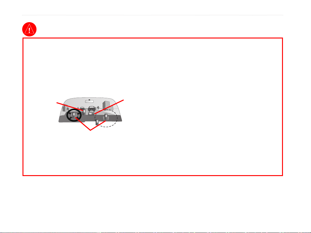
When installing the GPSMAP 96/96C in a vehicle, place
the unit securely so that it does not interfere with vehicle
operating controls or obstruct the driver’s view of the road
(see diagram).
Do not mount
where driver’s
eld of vision is
blocked.
Do not place
unsecured on
the vehicle
dash.
Minimize the amount of time spent viewing the screen of
the GPSMAP 96/96C while driving and use voice prompts
when possible. Do not enter destinations, change settings,
or access any functions requiring prolonged use of the unit’s
controls while driving. Pull over in a safe and legal manner
before attempting such operations.
When navigating, carefully compare information displayed
on the GPSMAP 96/96C to all available navigation sources,
including information from street signs, visual sightings,
and maps. For safety, always resolve any discrepancies or
questions before continuing navigation.
Use the electronic chart in the GPSMAP 96/96C only to
Do not mount in front of an airbag
eld of deployment.
Always operate the vehicle in a safe manner. Do not
become distracted by the GPSMAP 96/96C while driving,
and always be fully aware of all driving conditions.
facilitate, not to replace, the use of authorized government
charts. Ofcial government charts and notices to mariners
contain all information needed to navigate safely.
When navigating in an aircraft, use the GPSMAP 96/96C
only as an aid for VFR navigation. Use terrain and obstacle
data only as an aid to situational awareness.
WARNING: This product, its packaging, and its components contain chemicals known to the State of California to cause cancer,
birth defects, or reproductive harm. This Notice is being provided in accordance with California’s Proposition 65. If you have any
questions or would like additional information, please refer to our Web site at http://www.garmin.com/prop65.
iv 96/96C Owner’s Manual
Page 7

Caution
IntroductIon >
Failure to avoid the following potentially hazardous
situations may result in injury or property damage.
The GPSMAP 96/96C is designed to provide you with
route suggestions. It does not reflect road closures or road
conditions, trafc congestion, weather conditions, or other
factors that may affect safety or timing while driving.
Use the GPSMAP 96/96C only as a navigational aid. Do
not attempt to use the GPSMAP 96/96C for any purpose
requiring precise measurement of direction, distance,
location, or topography. This product should not be used to
determine ground proximity for aircraft navigation.
Map Data Information: One of the goals of Garmin is to provide customers with the most complete and accurate cartography
that is available to us at a reasonable cost. We use a combination of governmental and private data sources, which we identify in
product literature and copyright messages displayed to the consumer. Virtually all data sources contain inaccurate or incomplete
data to some extent. In some countries, complete and accurate map information is either not available or is prohibitively
expensive.
NOTICE TO DRIVERS IN CALIFORNIA AND MINNESOTA: State law prohibits drivers in California and Minnesota from
using suction mounts on their windshields while operating motor vehicles. Other Garmin dashboard or friction mounting options
should be used. Garmin does not take any responsibility for any nes, penalties, or damages that may be incurred as a result of
disregarding this notice. (See California Vehicle Code Section 26708(a); Minnesota Statutes 2005, Section 169.71.)
96/96C Owner’s Manual v
The Global Positioning System (GPS) is operated by the
United States government, which is solely responsible for
its accuracy and maintenance. The government’s system
is subject to changes which could affect the accuracy and
performance of all GPS equipment, including the GPSMAP
96/96C. Although the GPSMAP 96/96C is a precision
navigation device, any navigation device can be misused or
misinterpreted and, therefore, become unsafe.
Page 8

IntroductIon >
Caring for the GPSMAP 96/96C
The GPSMAP 96/96C case is constructed of
high quality materials and does not require user
maintenance except cleaning.
Cleaning the Case
Clean the unit’s outer casing (except for the screen)
using a cloth dampened with a mild detergent solution
and then wipe dry. Avoid chemical cleaners and
solvents that can damage plastic components.
Storage
Do not store the GPSMAP 96/96C where prolonged
exposure to temperature extremes can occur (such as
in the trunk of a car) as permanent damage can result.
User information, such as waypoints and routes are
retained in the unit’s memory without the need for
external power. It is always a good practice to back
up important user data by manually recording it or
downloading it to a PC (transferring it to MapSource).
Water Immersion
Cleaning the Screen
The GPSMAP 96/96C screen should be cleaned using
a soft, clean, lint-free cloth. Water, isopropyl alcohol,
or eyeglass cleaner can be used if needed. If these
are used, apply the liquid to the cloth and then gently
wipe the screen with the moistened cloth.
The GPSMAP 96/96C is waterproof to IEC Standard
60529 IPX7. It can withstand immersion in 1 meter
of water for 30 minutes. Prolonged submersion can
cause damage to the unit. After submersion, be certain
to wipe and air dry the unit before reuse or charging.
vi 96/96C Owner’s Manual
Page 9
GettInG started
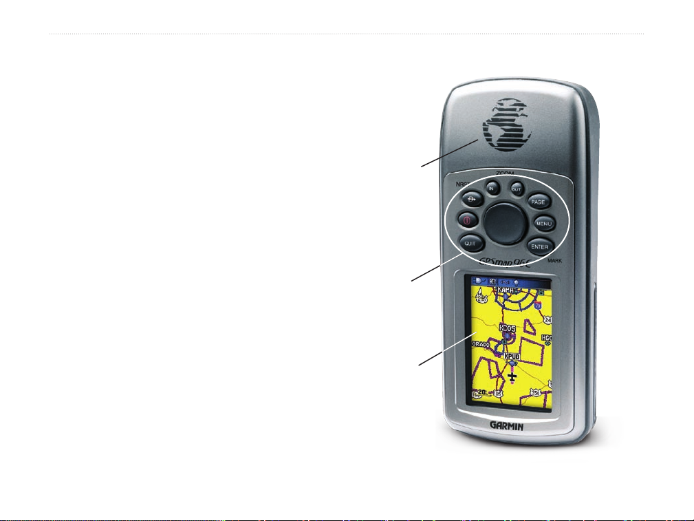
Unit Overview
The GPSMAP 96/96C is an all-in-one, versatile
aviation, automotive, and marine navigator- perfect
for air, land, or water. This portable GPS navigator
features a 256-color TFT screen, a built-in basemap,
Jeppesen aviation database, and auto routing to
provide you with automatically generated turn-by-turn
directions.
Internal
antenna
Keypad
256-Color TFT
backlit screen
GettInG Started >
96/96C Owner’s Manual 1
Page 10
GettInG Started >
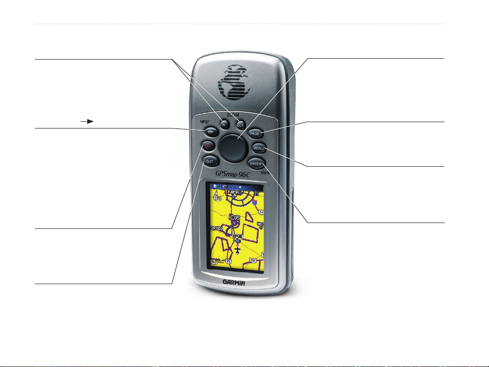
IN/OUT Zoom Keys
• From the Map Page, press to zoom in or
out.
• From any other page, press to scroll up or
down a list.
DIRECT TO D/NRST Key
• Press and release at any time to view the
Go To Pages for a destination when in
Aviation Mode or the Find Menu when in
Automotive and Marine Modes.
• Press and hold for Nearest Airports
(Aviation) Recent Finds (Automotive) or
MOB (Marine) Mode.
POWER/BACKLIGHT Key
• Press and Hold to turn unit On/Off
• Press and Release to adjust backlighting
(Contrast - GPSMAP 96).
QUIT Key
• Press and release to cancel data entry or
exit a page.
ROCKER Key
• Move Up/Down or Right/Left to move
through lists, highlight elds, on-screen
buttons, icons, enter data or move the
map panning arrow.
PAGE Key
• Press to cycle through the main pages.
• Press and hold to change the usage mode.
MENU Key
• Press and release to view options for a
page.
• Press twice to view the Main Menu.
ENTER/MARK Key
• Press and release to enter highlighted
options, data or conrm on-screen
messages.
• Press and hold at any time to mark your
current location as a waypoint.
2 96/96C Owner’s Manual
Page 11
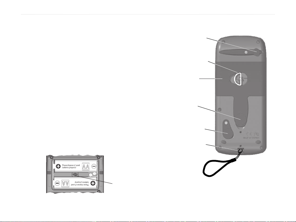
Installing the Batteries
The GPSMAP 96/96C operates on two AA batteries
(not included), which are located in the back of the
unit. Alkaline or NiMH batteries (see page 103 for
setting the battery type) can be used. Stored data is
not be lost when batteries are removed.
GettInG Started >
External Antenna
Connector
(under weather cover)
Battery Compartment
Locking D-Ring
To install batteries:
1. Remove the battery cover from the back of
the unit. Turn the D-Ring 1/4 turn counterclockwise and then pull.
2. Insert the batteries, observing the proper
polarity. A polarity diagram can be found
molded into the battery compartment.
(under weather cover)
3. Reinstall the battery cover by reinserting the
locking pin in the back of the unit. Turn the
D-Ring 1/4 turn clockwise to lock in place.
Locking
Pin Slot
Battery Compartment
96/96C Owner’s Manual 3
Battery
Compartment
Cover
Power/Data Cable
Connector
(Serial Port)
USB Connector
(under weather cover)
Carry Lanyard
connection
Page 12
GettInG Started >
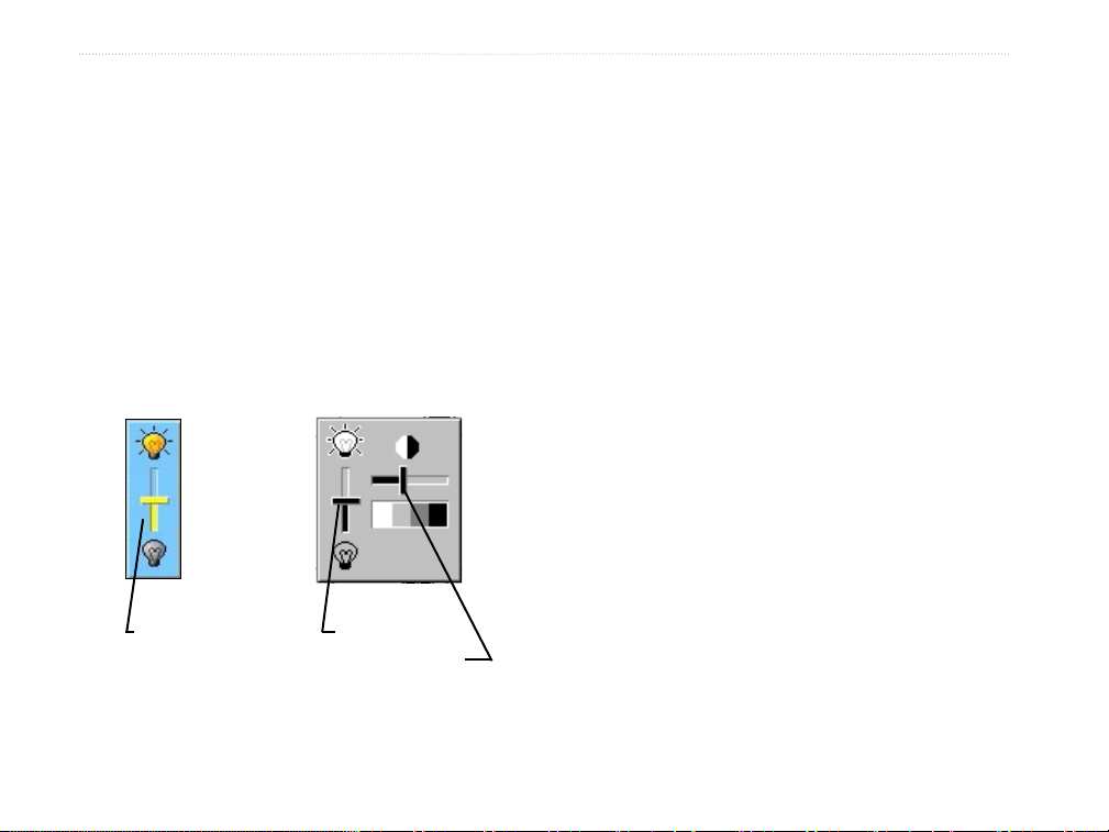
Adjusting the Backlight and Contrast
You may want to adjust the backlight to see the screen
better. You can also adjust the contrast if using the
GPSMAP 96.
To adjust the backlight level:
1. Press and quickly release the POWER key.
2. Press the ROCKER up to increase the
brightness or down to decrease the brightness.
3. Press ENTER or QUIT to close.
GPSMAP
96C Backlight
Adjustment
GPSMAP 96
Backlight and
Contrast Adjustment
To adjust the contrast level: (GPSMAP 96
only):
1. Press and quickly release the POWER key.
2. Press the ROCKER to the right to increase the
contrast or to the left to decrease the contrast.
3. Press ENTER or QUIT to close the Backlight/
Contrast adjustment window.
4 96/96C Owner’s Manual
Page 13
BaSIc operatIon >
basIc operatIon
Turning On the GPSMAP 96/96C
The rst time you power up your new GPSMAP
96/96C, the receiver must collect satellite data and
establish its present position. To ensure proper
initialization, the GPSMAP 96/96C is shipped from
the factory in AutoLocate mode, which allows the
receiver to “nd itself” anywhere in the world. Before
you turn on the unit to start initialization, be sure
that it has a clear and unobstructed view of the sky to
receive satellite signals.
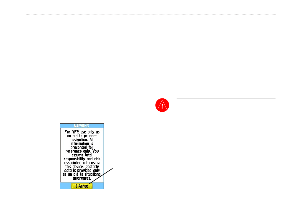
Press ENTER
to acknowledge
and show the
Satellite Page.
Warning and Information Page
To turn On and Off the GPSMAP 96/96C:
1. Press and hold the Power key. When the unit
powers on, a tone sounds, and the rst page
appears.
2 After a few seconds, a Warning/Information
Page appears. To acknowledge that you
have read and understand the warning, press
ENTER to continue.
3. To turn off the GPSMAP 96/96C, press and
hold the POWER key again.
WARNING: When you agree with the
statements on the Warning Page it is assumed
that you understand that the GPSMAP 96 and
GPSMAP 96C are intended as aids to navigation
only. That the navigation information and
obstacle data provided by the GPSMAP 96 and
GPSMAP 96C is intended as an aid to situational
awareness only. That it does not take precedence
over accepted practices for safe navigation using
Visual Flight Rules and that you have accepted
the responsibilities and risks associated with
using these devices.
96/96C Owner’s Manual 5
Page 14
BaSIc operatIon >
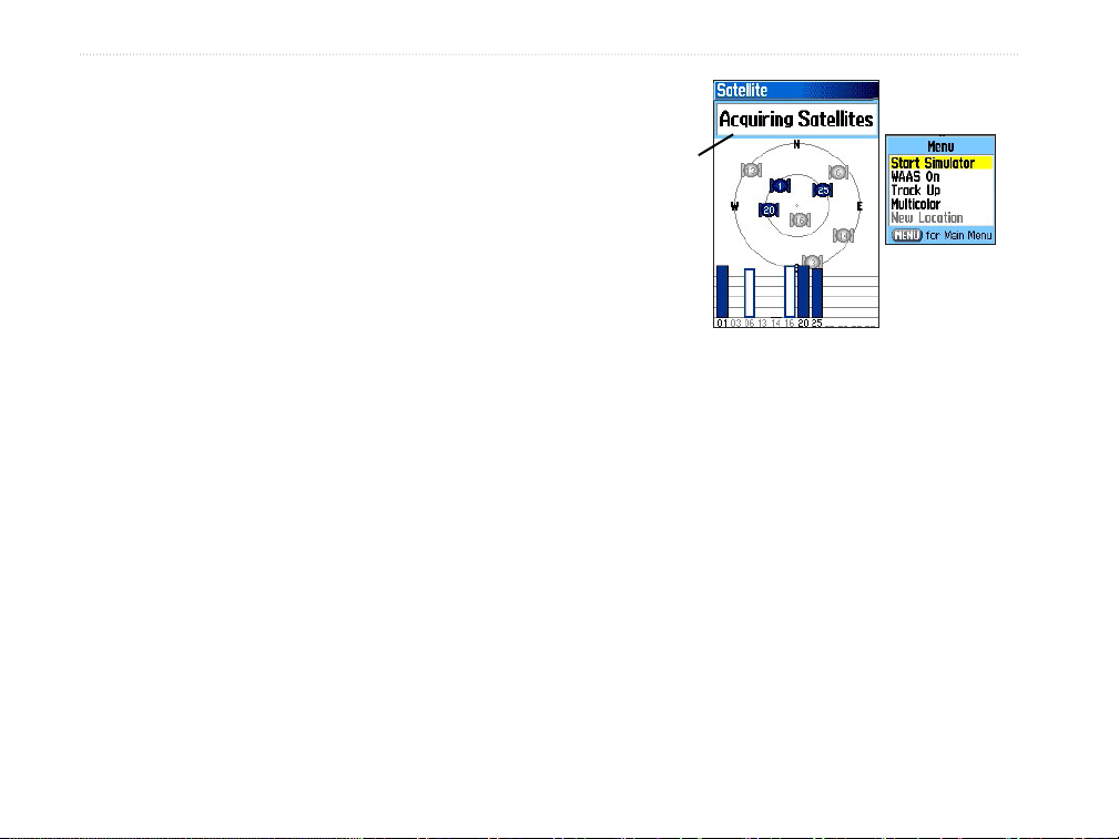
Initializing the GPSMAP 96/96C
As soon as you turn the GPSMAP 96/96C on, it
begins searching for satellites in your area and should
acquire a x within a few minutes. When you have
cycled through the Start Up and Warning Pages, the
Satellite Page appears. At the top of the screen, the
unit shows the status as “Acquiring Satellites.” A
sky view array depicting the approximate location of
overhead satellites is shown in the center of the page.
When a signal of sufcient strength is received the
satellite is identied by its assigned number. The sky
view represents a theoretical dome directly over your
current location with a pointer to indicate orientation.
While viewing the Satellite Page, a signal strength bar
for each satellite the unit is trying to acquire appears
at the bottom of the screen with the satellite numbers
shown below each bar.
The progress of satellite acquisition is shown in three
stages:
•
•
•
Status Field
Options
Menu
Satellite Page
No signal strength bars—the receiver is
looking for the satellites.
Hollow signal strength bars—the receiver
has found the indicated satellites and is
collecting data.
Solid signal strength bars—the receiver has
collected the necessary data and the satellites
are ready for use.
6 96/96C Owner’s Manual
Page 15
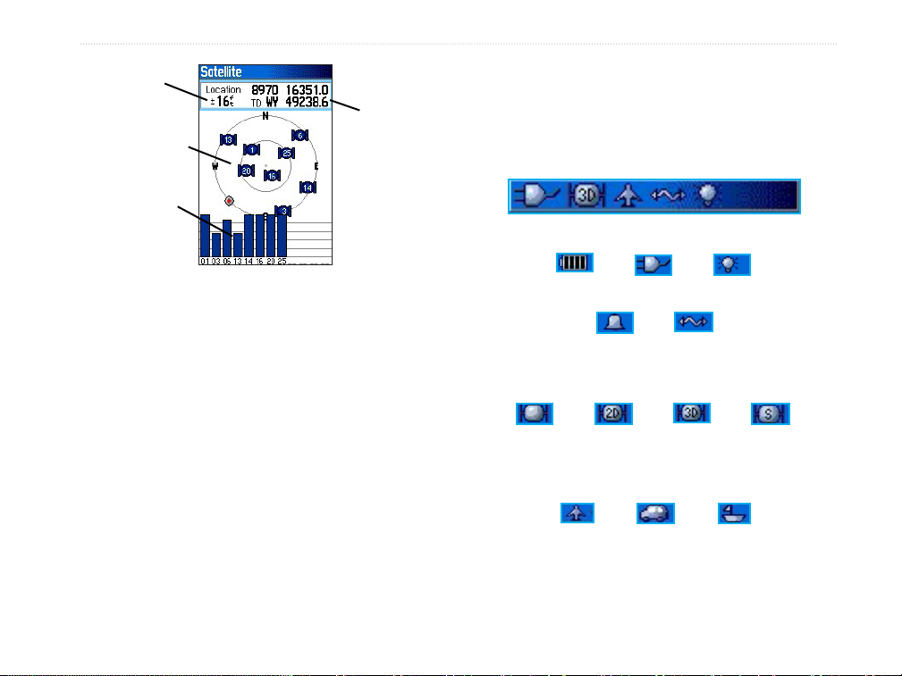
BaSIc operatIon >
GPS Accuracy
Satellite Array
“Sky View”
Signal Strength
Bars
Current
Location
Satellite Page
Status Bar
At the top of each page, a Status Bar provides the
current status for several unit features that are not
otherwise noticeable when operational.
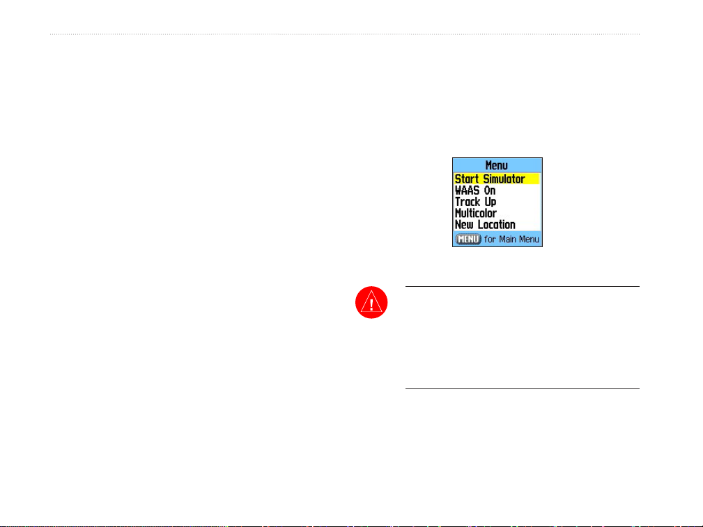
Press MENU to view options for Simulator, WAAS,
Track Up/North Up, Multicolor screen, and New
Location to use the Map Page to establish your
approximate location. Once the receiver has collected
information from and is xed on at least three
satellites, the unit is “Ready to Navigate” and you can
advance to the Map Page.
System Symbols
Battery
Power
Satellite Status Symbols
Acquiring
Satellites
Navigation Mode Symbols
Aviation
Mode
Auxiliary
Power
Alarm Set
2-D
Navigation
Automotive
Mode
Backlight
On
USB
Connected
3-D
Navigation
Marine
Mode
Simulating
Navigation
96/96C Owner’s Manual 7
Page 16
BaSIc operatIon >
Changing Usage Modes
To switch usage modes:
1. Press and hold PAGE.
2. Use the ROCKER to select either Aviation,
Automotive, or Marine, and press ENTER.
How to Operate Unit Features
The GPSMAP 96/96C unit’s advanced keypad system
is designed to allow quick, convenient selection of
navigation options and data entry. Many keys on
the keypad have dual functions, when pressed and
released they perform a primary function and when
On-Screen Messages
Whenever a signicant event in unit operation occurs,
an on-screen message appears to advise you. In many
instances a remedy is also provided. Pressing ENTER
acknowledges and closes the message window.
pressed and held they perform a secondary function.
Many keys change functions when a particular
feature page is shown. When a eld is selected on the
screen, it is highlighted. Selection is controlled by the
ROCKER.
You can use the Message Log feature to record those
messages for later review. You can also select only
certain types of messages for storage on the Message
Log. A message lter allows you to identify the types
of messages for review.
Cursor Position
(Highlight is Yellow)
GPSMAP 96C
For more detailed information about using the
Message Log feature, refer to page 122.
On-Screen Buttons
grayed-out when
Data Fields
(Buttons are
inactive)
8 96/96C Owner’s Manual
Page 17
BaSIc operatIon >
The following features are referred to throughout this
manual.
Cursor—the highlighted area on the screen that can
be moved up/down/left/right with the ROCKER to
select individual elds. Moving the cursor makes a
selection, begins data entry, or scrolls through a list.
Field—the location on a page where data or an option
Default—a factory set system format is followed
unless you change a setting. For example, the
default setting for speed readings in Marine Mode is
nautical miles per hour (knots), but may be changed
to kilometers or miles per hour. Once a setting is
changed, the new setting is retained until another
change is made or a Restore Default option is
selected.
can be entered and shown. The cursor is placed on
a eld using the ROCKER to begin data entry or
selection of options.
On-Screen Button—use the ROCKER to highlight a
button and press Enter to select the action.
Scroll Bar—when viewing a list of items too long to
shown on the screen, a scroll bar appears along the
right side of the list. The position of the scroll bar
indicates which portion of the list is currently shown.
The height of the scroll bar indicates the number of
items in the list. To scroll through a list, press up or
down on the ROCKER.
Options Menu
with Scroll Bar
Default Settings
Option
On-Screen Operating Features
96/96C Owner’s Manual 9
Page 18
BaSIc operatIon >
Selecting Options and Entering Data
You can select and start options and enter data to
customize your GPSMAP 96/96C to t your personal
needs. This requires movement of the cursor, which is
identied in this manual as highlighting, selecting, or
choosing an item in a list or a eld on the screen. Use
ENTER and ROCKER to select options, enter names
The QUIT moves backwards through your steps.
When pressed repeatedly, the QUIT returns to the
main page you started from.
3. Press
4. To exit a menu or return to the previous
ENTER to start the feature. If another
window appears with more options, select the
an option, and press ENTER again.
setting, press QUIT.
and numbers in data elds, and start your selections.
To select an
option: use the
ROCKER to
highlight it and
press ENTER
to start.
Options Menu
Options that
are grayed-
out are not
available.
To select and start an option:
1. With any page shown, press MENU. An
Options Menu appears with a list of optional
features for that page.
2. Use the ROCKER to move the cursor up or
down the menu to highlight your selection.
10 96/96C Owner’s Manual
Use the
ROCKER to
highlight an
on-screen
button, and
then press
ENTER.
On-Screen Buttons
Page 19

BaSIc operatIon >
To select and start an on-screen button:
Use the ROCKER to highlight the on-screen
button, and press ENTER.
To enter data in a data eld:
1. Use the ROCKER highlight the data eld, and
press ENTER to start the eld.
2. Press up or down on the ROCKER to select
characters. Press right to move to the next
character eld or press left to move back to the
previous character eld. If there are two lines
of data, keep pressing right to drop down to
the next line.
To clear the entire data eld, move the cursor
to the left-most character eld and press left
once more on the ROCKER.
3. After entering the data, press ENTER to
conrm the change.
Not all elds are programmable, such as the date and
time. When you are on a page with elds that are not
selectable, the cursor skips over them.
4. To save the waypoint and exit the New
Waypoint Page, highlight OK, and press
ENTER.
Or
To cancel the waypoint and exit the New
Waypoint Page, highlight DELETE, and press
ENTER.
96/96C Owner’s Manual 11
Page 20
BaSIc operatIon >
Using Additional Map Data
Optional MapSource CD-ROMs enhance the
versatility of your GPSMAP 96/96C. With optional
MapSource City Select data, you can view listings
of nearby restaurants, lodging, shopping centers,
Simulator Mode
The main purpose of using a GPS receiver is for
navigating to a known position. To get a feel for
navigating with the GPSMAP 96/96C, it is a good
idea to practice navigation in Simulator Mode.
attractions and entertainment, and even retrieve
addresses and phone numbers for any listed location.
With optional BlueChart data, you can access
marine navaids, wrecks, obstructions, and anchorage
locations.
The included USB Interface Cable or an optional PC
Interface Cable (with a serial connector) is used to
transfer MapSource CD-ROM data to the unit.
To aid in learning to use the GPSMAP 96/96C, please
use the Simulator Mode. Simulator Mode is also
helpful for practicing with the unit indoors or when
no satellite signals are available. All waypoints and
routes created in Simulator Mode are retained in
memory for future use.
Start Simulator Option
WARNING: Do not attempt to navigate using
Simulator Mode, the GPS receiver is turned off.
Any Satellite Signal Strength Bars or navigation
shown are only simulations and do not represent
the strength of actual satellite signals or route
navigation.
12 96/96C Owner’s Manual
Page 21
BaSIc operatIon >
To put the unit into Simulator Mode using
the Main Menu:
1. Press MENU twice to show the Main Menu.
2. Highlight the Setup icon, and press ENTER to
show the Setup Menu.
3. Highlight the System icon, and press ENTER
to show the System Setup Page.
4. On the System Setup Page, highlight the
“GPS” eld, and press ENTER.
5. Select Simulator, and press ENTER. Press
QUIT to return to your previous page.
To put the unit into Simulator Mode using
the Satellite Page:
1. Press the PAGE repeatedly until the Satellite
Page is shown.
2. Press MENU to open the Options Menu.
3. Highlight Start Simulator, and press ENTER.
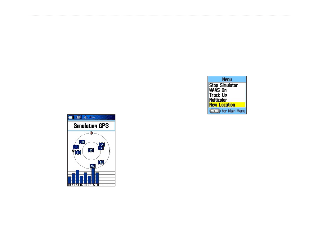
To enter a New Location:
1. From the GPS Options Menu, select New
Location.
2. Select Use Map or Identier, and press
ENTER.
96/96C Owner’s Manual 13
Page 22

BaSIc operatIon >
To nd an aviation destination and
simulate navigation in Aviation Mode:
1. Press up on the ROCKER to increase the
simulated speed. The aircraft symbol now
begins moving on the magenta route line.
2. Press QUIT or PAGE to return to the Map
Page. Press in or out to adjust the zoom
level. Observe the movement of the aircraft
symbol as the unit simulates navigation.
Press PAGE or QUIT to view the simulated
navigation on the other main pages.
Using DIRECT TO Key
The GPSMAP 96/96C includes an internal Jeppesen
database, and memory for up to 1,000 user-created
waypoints. The GPSMAP 96 accepts 22MB, while
the GPSMAP 96C accepts 118MB of MapSource
data. The Jeppesen database provides position and
facility information for airports, VORs, NDBs, and
more. Updates to the Jeppesen database are available
every 28 days online (www.garmin.com). The update
Windows®-compatible PCs and requires the USB
Cable to connect to a PC. The following information
is provided from the Jeppesen database:
Airport—* identier, facility name, city/state/
country, position (latitude/longitude), eld elevation,
available fuel types, runway designations/layout,
runway surface(s), runway length(s), runway width(s),
runway lighting, runway trafc pattern direction
data, communication frequencies, and published
approaches.
Weather—associated with an airport (ASOS, ATIS,
and AWOS).
®
VORs—* identier, facility name, city/state/country,
position (latitude/longitude), frequency, service
volume (high, low, terminal), and type (such as VORDME, TACAN, and VORTAC).
NDBs—* identier, facility name, city/state/country,
position (latitude/longitude), and frequency.
program is designed to operate on
14 96/96C Owner’s Manual
Page 23
BaSIc operatIon >
Intersections—identier, nearest VOR, radial
and distance from nearest VOR, position (latitude/
longitude), and region/country.
ARTCC—Air Route Trafc Control Centers.
Airspace—boundaries (Class B, Class C, Class
D, Control Zones, SUAs, and MOAs), controlling
agency, and vertical boundaries.
FSS—Flight Service Stations.
User Waypoints—name, symbol, position (lat/lon),
elevation, and comment.
Also, in Marine Mode, pressing and holding
DIRECT TO D creates a Man OverBoard waypoint
and starts navigating to that point.
* Symbology used for NDBs, VORs, and airports are
consistent with those used on a sectional chart.
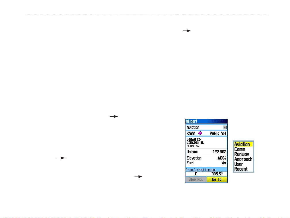
Go To Aviation
The Go To Aviation Page shows the (Airport)
identier, CTAF or tower frequency, facility name,
city/state/country, available fuels, eld elevation,
distance and bearing from your current location, and
airport position (latitude/longitude).
In Aviation Mode, press DIRECT TO D to show
the Go To Page, which allows you to select an airport
or navaid, a recently (previously) used waypoint, or a
user-created waypoint as your destination.
When a Go To or route is currently in use, pressing
DIRECT TO D key shows a detailed information
page for the active waypoint.
In Marine or Automotive Mode, press DIRECT TO D
to show the Find menu, which allows you to select a
destination waypoint.
Aviation Mode Go To Page
Options
List
96/96C Owner’s Manual 15
Page 24
BaSIc operatIon >
To Go To an airport or navaid:
1. Press DIRECT TO D to show the Go To
Page. If Aviation is not highlighted, press the
ROCKER until the top eld is highlighted.
Press the ROCKER right or left until Aviation is
selected.
2. Use the ROCKER to enter the airport, facility
name, intersection, VOR or NDB. Press up
and down to change the highlighted character
and to move to the next character eld. As you
scroll through the characters the GPSMAP
96/96C shows any database entries with the
same characters you have entered to that
point. If more than one entry exists in the
database for the characters you have entered,
a window appears listing the entries. Use
the ENTER and ROCKER keys to select a
waypoint from the duplicate list.
3. Press ENTER when the waypoint is shown.
4. With the on-screen Go To button highlighted,
press ENTER. A course is plotted from your
present position to the selected destination
waypoint.
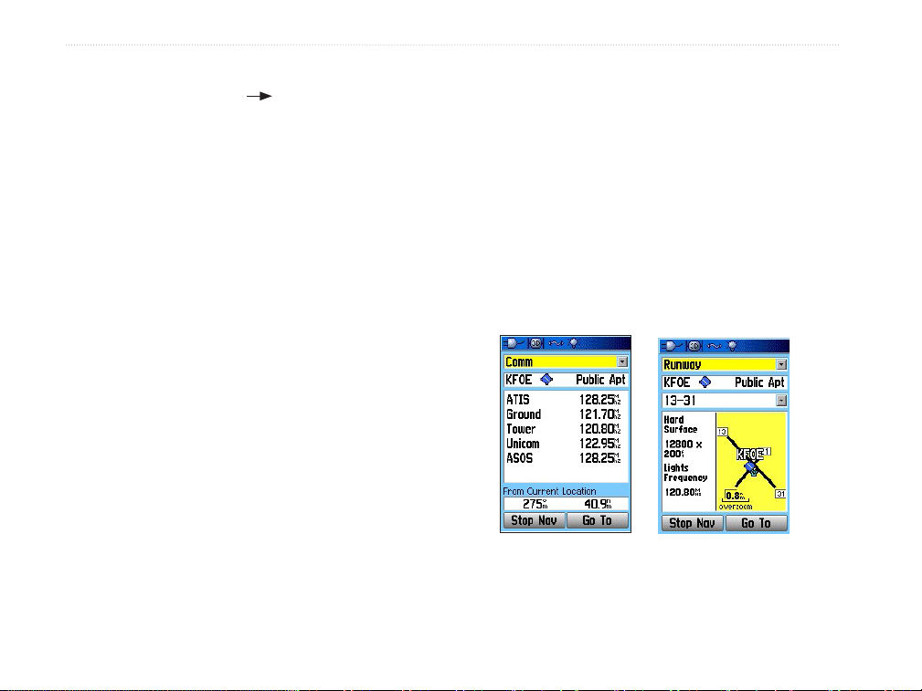
Go To Comm
The Go To Comm Page contains identier, frequency,
and frequency type. Available frequency types are:
ATIS, Pre-taxi, Clearance, Ground, Tower, Unicom,
Multicom, AWOS, ASOS, Departure, Approach,
Arrival, Class B, Class C, Class D, TMA, CTA, and
TRSA.
As you view frequencies for various airports, some
appear with an asterisk (*). This denotes a frequency
with usage restrictions.
Comm Identier
Runway Identier
16 96/96C Owner’s Manual
Page 25

BaSIc operatIon >
To view usage restrictions for a
communication frequency:
1. Select Comm with the ROCKER in the top
eld. Use the ROCKER to highlight any
frequency with usage restrictions (as denoted
by an asterisk), and press ENTER. A Usage
Restrictions Page appears describing the
restrictions for the selected frequency.
2. To return to the Comm information page, press
ENTER.
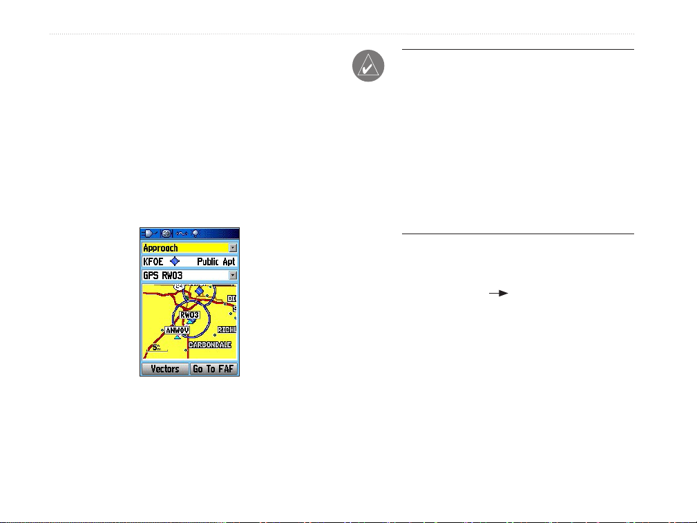
Go To Approach
The Go To Approach Page shows identier, approach
name, nal approach x (FAF), and missed approach
point (MAP), distance and bearing from your current
location, and airport position (latitude/longitude).
Available approach types include ILS, localizer,
RNAV, GPS, VOR, VOR/DME, and NDB. Approach
name, nal approach x (FAF), and missed approach
point (MAP) appear ONLY if the airport has a
published approach.
Go To Runway
The Go To Runway Page shows identier, runway
designations, runway layout (map), trafc pattern
direction, surface type, lighting frequency, length,
width, distance and bearing from your current
location, and airport position (latitude/longitude). Use
the third eld to change between multiple runway
information.
When viewing information for Runway or Approach,
use the ROCKER to highlight the runway
designation or approach name, and press ENTER.
Then press up or down on the ROCKER to scroll
through available runways/approaches. Press Enter to
view additional information for a runway/approach.
96/96C Owner’s Manual 17
Page 26
BaSIc operatIon >
Select Approach
The Select Approach option replaces a destination
airport with the sequence of waypoints for the
selected approach. Keep in mind that the airport must
have a published approach (GPS, RNAV, VOR, NDB,
localizer, or ILS) and only the nal course segment
(from nal approach x to missed approach point) of
the published approach is available in the
GPSMAP 96/96C.
Approach
Identier
NOTE: When using a route, and on the nal leg
of the route to the destination airport, the Select
Approach option allows you to quickly retrieve
and select available approaches. This option
overrides your current route. The original route
is still available for later use. The approaches
provided in the Jeppesen database are for
monitoring purposes only. The GPSMAP 96/96C
is not an IFR-approved instrument and should
not be used as a primary source of navigation
guidance in instrument conditions.
To select an approach using the Go To
page:
1. Press DIRECT TO D to show the Go To
Page.
2. Use the ROCKER to highlight Approach.
3. Use the ROCKER to select the approach from
the third eld, and press ENTER.
4. Use the ROCKER to select Vectors or FAF,
and press ENTER. The GPSMAP 96/96C
removes the destination airport from the Go To
and replaces it with the approach waypoints.
18 96/96C Owner’s Manual
Page 27

BaSIc operatIon >
To select an approach using the Active
Route Page:
1. Access the Active Route Page, and press
MENU.
2. Use the ROCKER to choose Select
Approach.
3. Select an Approach from the window.
4. Indicate Yes or No in the “Vectors?” window.
To cancel vectors and/or an approach from
the Go To Approach Page:
1. Access the Go To Approach Page.
2. Press MENU. Highlight Cancel Approach or
Cancel Vectors, and press ENTER.
To cancel vectors and/or an approach from
the Active Route Page:
1. Access the Active Go To Page, and press
MENU to open the Options Menu.
2. Highlight Cancel Vectors, and press ENTER
to navigate directly to the FAF.
Or
Highlight Cancel Approach or Select
Approach, and press ENTER to change.
96/96C Owner’s Manual 19
Page 28
BaSIc operatIon >
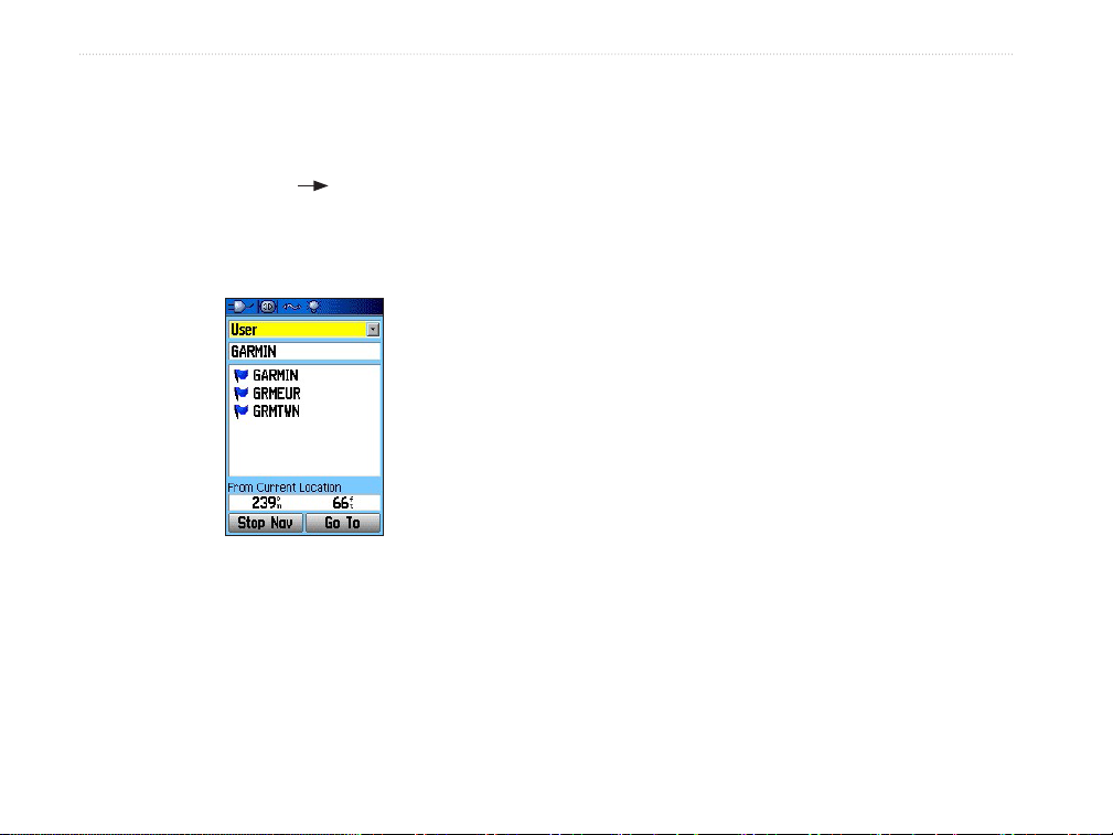
Go To User and Recent
To Go To a recently used waypoint or usercreated waypoint:
1. Press DIRECT TO D to show the Go To
Page. Use the ROCKER to highlight the rst
eld. Press the ROCKER to the right or left
until Recent or User is selected.
User List for
Waypoints
2. Use the ROCKER to highlight a waypoint
from the list. From User, you can also select
the top waypoint name line and then spell
out the waypoint name using ENTER and the
ROCKER.
3. Press ENTER when a waypoint is highlighted.
With the on-screen Go To button highlighted,
press ENTER. A course is plotted from your
present position to the selected destination
waypoint.
20 96/96C Owner’s Manual
Page 29
BaSIc operatIon >
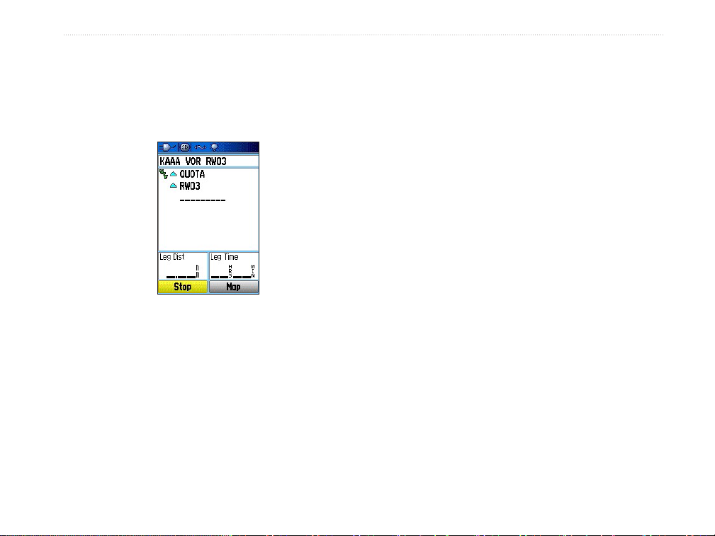
Understanding Vectors
The Vectors option that appears at the last step of
selecting an approach determines how you navigate to
the nal approach waypoint in the approach.
on the graphic HSI remains off-center until you are
established on this nal approach course. The Map
Page shows an extension of the nal approach course
using a bold magenta line. The HSI automatically
slews (rotate to show the direction) to the inbound
course. On the Active Route (or Active Approach)
Page, a Vector to Final symbol appears adjacent to the
rst approach waypoint.
If No is selected for the Vectors? or the Go to FAF
option is selected from the Approach Go To Page,
the GPSMAP 96/96C creates a straight-line course
directly to the rst waypoint in the approach (from
wherever you are when you initiate the approach).
Active Approach Page
This works much like any other route with course
guidance from point-to-point and a turn usually
If you select Vectors, the GPSMAP 96/96C creates
required as you cross each waypoint.
an extension of the nal course, beyond the nal
approach waypoint in the database (nal approach x
[FAF]). The GPSMAP 96/96C provides no guidance
to the inbound course. The course deviation needle
96/96C Owner’s Manual 21
Page 30
BaSIc operatIon >
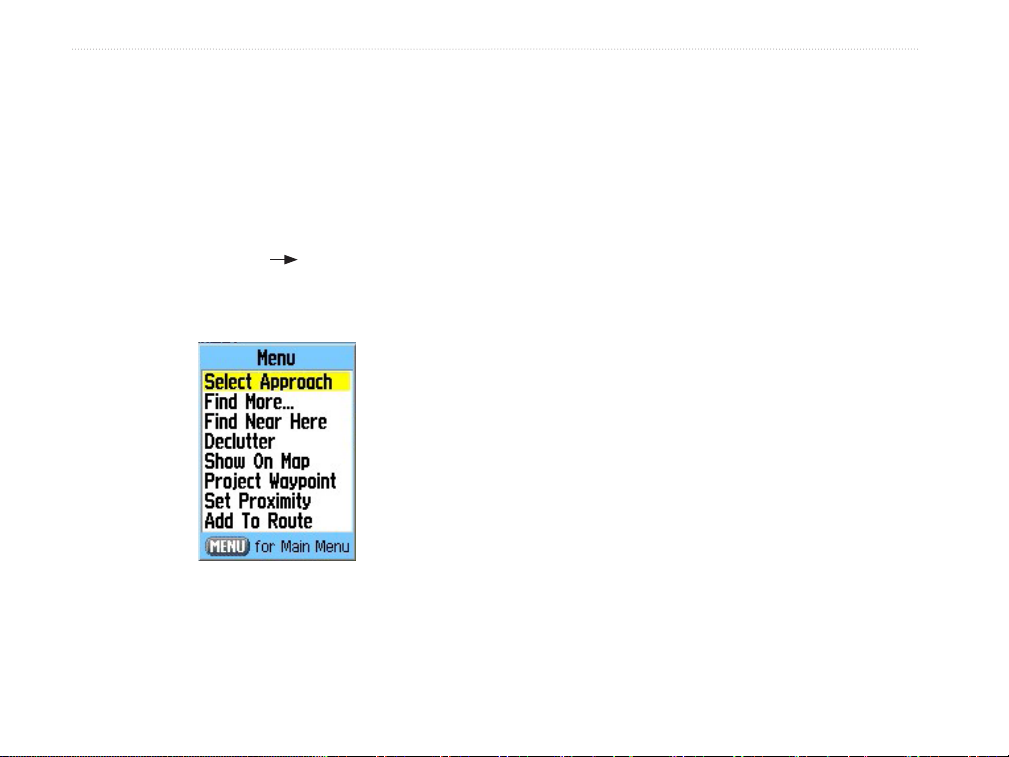
Go To Page Options Menu
The available options are described below. In the
sections following, some options, such as Show
Find More—directs you to the Find Menu.
Find Near Here—allows you to nd other places
near the waypoint or point of interest specied.
Details, also have instructions detailing how to use the
option.
Declutter On/Off—activates three layers of map
detail. Select this option multiple times to increase or
To access the Go To Page Options Menu:
1. Press DIRECT TO D. The Go To Page
opens
2. Press MENU.
decrease mapping detail. This option is only available
on the Runway and Approach Go To Pages.
Show On Map—takes you to the map page and
zooms onto the location.
Project Waypoint—allows you to create a waypoint
at a specic distance and bearing from the location
selected.
Set Proximity—allows you to establish an alarm
circle in a user dened distance around a waypoint.
Add To Route—places the location in an existing
route or creates a new route with the location as the
Go To Options Menu
destination.
Select Approach—shows a window with the available
approaches for that specic airport. This option is only
available if the airport has published approaches.
22 96/96C Owner’s Manual
Page 31

BaSIc operatIon >
Nearest Pages Overview
In Aviation Mode, the Nearest function is accessed
by pressing and holding DIRECT TO D, providing
detailed information on the nearest airports, airport
weather sources, VORs, NDBs, intersections, and
user waypoints within 200 miles of your present
position. You can also access information regarding
the ve nearest FSS (flight service station) and center
(ARTCC) points of communication, along with their
associated frequency(s).
In Marine and Automotive Modes, DIRECT TO D
operates as a Find key, opening the Find Menu so you
can easily search the stored Waypoints, Cities,
Aviation, and Recent Find. Loading MapSouce data
provides additional search options.
Airport—nine nearest with identier, bearing to
and distance, length of longest runway, and common
trafc advisory (CTAF) or tower frequency.
Wx (Airport Weather Sources)—nine nearest
airport weather information sources, including
AWOS, ASOS, and ATIS.
VOR (VHF Omnidirectional Radio Beacons)—nine
nearest with identier, facility type (symbol), bearing
to and distance, and frequency.
NDB (Non Directional Beacons)—nine nearest
with identier, facility type (symbol), bearing to and
distance, and frequency.
INT (Intersection)—nine nearest with identier,
bearing to and distance.
User (Waypoints)—nine nearest with name, bearing
to and distance.
96/96C Owner’s Manual 23
Page 32

BaSIc operatIon >
ARTCC (Air Route Trafc Control Center)—ve
nearest with bearing to and distance and frequency(s)
FSS (Flight Service Station)—ve nearest with
To view additional information for a nearby
airport, navaid, or user waypoint:
1. Show the nearest pages, and select a category
bearing to and distance, frequency(s) and VOR (for
duplex operations)
Airspace—up to nine (depending on number of alerts
provided) with name, time to entry (when applicable),
and status.
To view the Nearest Pages in Aviation
Mode:
1. Press and hold DIRECT TO D.
2. Use the ROCKER to select the category in the
top eld.
NOTE: When an airspace alert is shown, press
and hold DIRECT TO D to automatically
show nearest airspace information. Press
and hold DIRECT TO D a second time
to quickly show the nearest airports list.
Additional information for airports, navaids,
and user-created waypoints is available from the
information pages.
2. Use the ROCKER to highlight a waypoint on
On airport information pages, use the
as described above.
Nearest Airport
List
the list, and press Enter. The corresponding
waypoint information page appears.
ROCKER to select a category from the top
eld to show the airport data.
24 96/96C Owner’s Manual
Page 33

BaSIc operatIon >
4. Press QUIT to return to the Nearest Pages.
You can also highlight any one of the onscreen buttons to perform that action, such as
Delete, Map, or Go To.
To select a nearby waypoint as your
destination:
1. Show the nearest pages and select a category.
2. Use the ROCKER to highlight a waypoint,
press DIRECT TO D, highlight Go To, and
press ENTER.
Go To page for selected
Airport
Setting Airport Criteria
From the Nearest Airport selection, an options
window allows you to lter out airports that do not
meet a dened criteria. This allows you to only show
airports with a surface type and sufcient runway
length.
To enter airport criteria:
1. Press and hold DIRECT TO D, and select
the Airport category.
2. Press MENU to show the Options Menu. Set
Airport Criteria appears, then press ENTER.
The current settings for runway surface and
minimum runway length appears.
96/96C Owner’s Manual 25
Page 34

BaSIc operatIon >
3. With the runway surface eld highlighted,
press ENTER. Use the ROCKER to select the
surface type, and press ENTER.
4. Highlight the minimum runway length eld,
and press ENTER. Use the ROCKER to enter
the minimum acceptable runway length. Press
ENTER.
NOTE: Use caution when changing the nearest
airport criteria. In an emergency, a short runway
is still typically preferable to an off-eld landing.
If you set the runway length too high or exclude
many runway surfaces, you may not be alerted to
a nearby airport that otherwise would be listed.
Any—shows any runway, regardless of surface type.
Hard Only—shows only runways with a concrete,
asphalt or similar surface.
Hard or Soft—shows all runways except water
landing facilities.
Water Only—shows only water landing facilities.
Minimum Runway Length—allows you to enter a
specic length for the shortest runway allowed.
Viewing Communication Frequencies
The Nearest Pages list up to ve nearest flight service
station (FSS) and air route trafc control center
(ARTCC) points of communication. The closest
communication point—along with frequency(s),
bearing to and distance—is shown rst, with
additional points available when selected. For duplex
operation, the corresponding VOR is listed (by
identier) and the transmit and receive frequencies are
denoted by a TX and RX respectively.
Communications
Frequencies Page
26 96/96C Owner’s Manual
Page 35

BaSIc operatIon >
To view additional communication
frequencies:
1. Press and hold DIRECT TO D to open the
Nearest Page.
2. Use the ROCKER to select the ARTCC or FSS
category.
3. Press the ROCKER down to highlight the
Center or Station eld (depending which
category you are on), and press ENTER.
4. Select the numbered item from the list and
press ENTER to show the communication
information. The lowest numbers on the list are
the closest comm points.
Viewing Airspace Information
When an airspace alert is provided, press DIRECT
TO D to automatically show nearby airspace
information. This information includes name, time to
entry (if applicable), and status. Normally, only one or
two airspace alerts occur at a time, but with sectorized
controlled airspace (such as many Class B areas)
you can have more. Status information can appear as
follows:
Ahead—your projected course takes you inside an
airspace within the next ten minutes or less.
Near—you are within two nautical miles of an
airspace, but not projected to enter it.
Near & Ahead—you are within two nautical miles of
an airspace and your current course takes you inside
the airspace.
Inside Airspace—you are within the boundaries of
the airspace.
From the Nearest Pages you can show additional
airspace information as well, such as floor and ceiling
Airspace Information Page
96/96C Owner’s Manual 27
limits or communication frequency(s).
Page 36

BaSIc operatIon >
To view additional airspace information:
1. When an airspace alert had been provided,
press and hold DIRECT TO D to show the
Nearest Pages and the airspace information.
If you are already viewing the Nearest Pages,
use the ROCKER to select the Airspace
category.
2. Use the ROCKER to select the airspace
alert entry on the page, then press ENTER.
An information page opens showing the
controlling agency, status, and oor/ceiling
limits.
3. To show a communication frequency for the
airspace, select the on-screen Frequencies
button, and press ENTER.
4. To return to the Nearest Pages, select the onscreen OK button, and press ENTER.
Navigating in Automotive Mode
Auto-Routing is a feature that makes it simple to
navigate to a destination when in Automotive Mode.
You can select a destination point from the Find Menu
and, press ENTER to show the Information Page for
that item. Highlight the on-screen Go To button at the
bottom of the page, and press ENTER to begin the
Auto-Routing process from your current location to
the destination.
You can select Faster Time, Shorter Distance, or
Off Road option windows show on the Map Page.
Select and option and the unit calculates the route.
When complete, the Map Page shows a bold magenta
(gray for the GPSMAP 96) line overlaying the roads
28 96/96C Owner’s Manual
Page 37

BaSIc operatIon >
on your route. A guidance message shows at the top of
the page with directions to the rst turn on the route.
As you approach each turn, a tone sounds and a Turn
Preview Page appears with a detailed graphic of the
turn.
Two other Main Pages, the Position Page and Pointer
Page provide travel information and directional
guidance. Selecting the Highway Page from the Main
Menu provides a graphic highway depicting your
route.
Going to a Destination in Marine Mode
Navigating to a destination in Marine Mode uses
the same features as the Automotive Mode with the
exception of the Auto-Routing feature.
Route Turn List Page
To view all turns on the route, press PAGE repeatedly
until the Active Route Page appears with a graphic
list of the turns. Highlight any turn eld and press
ENTER to view the Preview Page for that turn.
Marine Mode Route
on Map
96/96C Owner’s Manual 29
Page 38

BaSIc operatIon >
When you select a Find Menu item (typically from
the Marine Points list), select the Go To button. The
GPSMAP 96/96C creates a direct-line navigation
To start the MOB function:
1. Press and hold DIRECT TO D.
2. Select Yes, and press ENTER to conrm and
route to the destination. If you want to create a route
with turns at specic points, refer to the section on
Creating Routes. Once a route is started, the point to
point path is shown on the Map Page and supported
by the Main Page, Navigation Pages and the Highway
Page. The Active Route Page shows a list of the
waypoints on the route and indicates the next point on
Once a MOB has been started, an MOB waypoint
with an international MOB symbol is created and
the unit begins actively navigating to that point. Use
any of the Navigation Pages to guide you back to
the MOB point. The MOB waypoint is stored in the
waypoint list.
the route.
Man OverBoard (MOB)
The Man OverBoard (MOB) feature (functional only
in the Marine Mode) lets you simultaneously mark
and set a course to a position for quick response to
emergency situations.
begin navigating to the MOB.
MOB on Waypoints
list
30 96/96C Owner’s Manual
Page 39

BaSIc operatIon >
Creating and Using Waypoints
The Garmin GPSMAP 96/96C stores up to 1,000
alphanumeric waypoints with a user-dened icon,
comment, altitude, and depth available for each
waypoint. Waypoints can be created using three basic
methods:
Mark Waypoint Page
• Enter/Mark key—allows you to mark your
present position.
•
Graphically—allows you to dene a new
waypoint position from the Map Page using
the ROCKER to position the Arrow.
•
Text Entry—allows you to enter a new
waypoint’s position coordinates manually.
To mark your present position:
1. Press and hold ENTER/MARK until the Mark
Waypoint Page appears, then release it. You
see a default three-digit name and symbol for
the new waypoint.
2. To accept the waypoint with the default name
and symbol, use the ROCKER to highlight OK,
and press ENTER.
To change the any information on the Mark
Waypoint Page, highlight the appropriate
eld, and press ENTER. After entering and
conrming your changes, highlight OK, and
press ENTER.
96/96C Owner’s Manual 31
Page 40

BaSIc operatIon >
Creating Waypoints Graphically
3. Press and quickly release
Waypoints can also be quickly created with the Map
Page Arrow. When you move the cursor over a map
item, you see a highlighted description of that item.
The GPSMAP 96/96C uses the map item text shown
If you have highlighted a map feature, an
on the cartography as the default name and symbol for
the new waypoint.
4. The Waypoint Page appears. To accept the
To change the any information on the Waypoint
To create a new waypoint using the Map
Page:
1. Press PAGE until the Map Page appears.
2. Use the ROCKER to move the Arrow to a map
point or map feature.
ENTER to capture
the map point. Pressing and holding ENTER
marks your present position, not the map
Panning Arrow’s location.
information page is shown after you press
ENTER. Use the ROCKER to highlight Save
and press ENTER to save the item as a
waypoint.
waypoint with the default name and symbol,
highlight OK, and press ENTER.
Page, highlight the appropriate eld, and press
ENTER. After entering and conrming your
changes, highlight OK, and press ENTER.
32 96/96C Owner’s Manual
Page 41

BaSIc operatIon >
Additional Options for Creating
Waypoints
Waypoints can also be created by manually entering
To create a new waypoint by entering
location coordinates:
1. Create a waypoint using your favorite method
position coordinates through the Find feature of the
Main Menu. This method can be useful for creating a
waypoint at a specic latitude/longitude position from
a chart. You can also manually change the location
coordinates in the New Waypoint Page to create a new
2. Use the ROCKER to highlight the Location
waypoint.
To create a waypoint through the Main
Menu:
1. Press MENU twice to show the Main Menu.
2. Use the ROCKER to highlight the Find icon on
the page, and press ENTER to show the Find
Menu.
3. Open a Find category and select an item
from the list, then press ENTER to show the
information page and then select SAVE.
To change any information on the New
Waypoint Page, highlight the appropriate
eld, and press ENTER. After entering and
conrming your changes, press QUIT.
To change any of the other information on the
(discussed in previous sections). The new
waypoint is created with the next available
waypoint number and the receiver’s last known
position as the default name and position.
eld, and press ENTER. Use the ROCKER to
enter the position coordinates, and press QUIT
when nished.
New Waypoint Page, highlight the appropriate
eld, and press ENTER. After entering and
conrming your changes, press QUIT.
96/96C Owner’s Manual 33
Page 42

BaSIc operatIon >
A waypoint can also be created by projecting the
3. Use the ROCKER to highlight Project
distance and bearing from a specic location to a new
location.
To create a new waypoint by projecting its
4. To set the distance that the new waypoint is
location:
1. Create a waypoint using your favorite method
(discussed in previous sections) or select a
waypoint from the Find Waypoints List.
2. Press MENU to open the New Waypoint Page
Options Menu.
Project Waypoint
Option
To adjust the bearing that the new waypoint is
When you have adjusted all elements of the
5. Make any other changes to the new waypoint
Waypoint, and press ENTER to show the
Project Waypoint Page.
be projected beyond the original waypoint,
highlight the Distance portion of the From eld,
and press ENTER. Use the ROCKER to adjust
the distance, and press ENTER.
projected from the original waypoint, highlight
the Bearing portion of the From eld and
press ENTER. Use the ROCKER to adjust the
bearing, and press ENTER.
projected location, highlight Map or GoTo,
and press ENTER. To save the new waypoint,
press QUIT.
data (such as the name or symbol), then
highlight OK, and press ENTER.
34 96/96C Owner’s Manual
Page 43

BaSIc operatIon >
Waypoint Menu Options
As well as Project Location, additional options are
To calculate the average location:
1. Select “Average Location” from the Options
available by pressing MENU on the New Waypoint
and Waypoint Information Pages: Average Location,
2. The “Average Location” screen appears.
Find Near Here, Change Reference, Set Proximity,
Add To Route, View Sun and Moon, View Hunt
and Fish, and Reposition Here. Select Average
Location to have the unit take several sample location
measurements for the waypoint and recalculate for a
more accurate position reading. You can only average
the location for a waypoint you are currently marking
where you have a x on satellites from that location.
Waypoint Options
Menu
Menu.
Watch as the elds change as the unit
calculates the average position of the
waypoint. When you are satised with the
average location, press ENTER.
Estimated
Accuracy Field
Average Location
Page
96/96C Owner’s Manual 35
Page 44

BaSIc operatIon >
To nd an item (waypoint, etc) near a
selected waypoint :
Select Find Near Here to show the Find Menu,
and select a category to show a list of map
items near that waypoint.
To change the reference point for a
waypoint:
Select Change Reference to show a map
page with instructions at the bottom for placing
the Panning Arrow at a new reference point.
Press ENTER to change the reference and
return to the waypoint page.
Use Panning
Arrow to
define a new
reference.
Change Reference Page
To set a proximity alarm for a waypoint
location:
1. Select Set Proximity from the Options Menu.
2. Press ENTER to show the Proximity
Waypoints Page. Then follow setup
instructions on page 113.
Set Proximity
Waypoint
To add a new waypoint to a route:
1. Select Add To Route from the Options Menu.
2. The Routes screen appears. Highlight the
show route or select New Route, and press
ENTER.
36 96/96C Owner’s Manual
Page 45

BaSIc operatIon >
3. A “Successfully Added Waypoint” message
appears. Press ENTER to acknowledge and
exit.
To view Sun and Moon positions at a
waypoint location:
Select View Sun and Moon, and press
ENTER to show Sun and Moon positions for
that location. See the section on Sun and
Moon tables for detailed information.
View Sun and Moon
To view Hunt and Fish predictions for a
waypoint location:
Select View Hunt and Fish, and press
ENTER to show Hunt and Fish predictions for
that location. See the section on Hunt and Fish
tables for detailed information.
View Hunt and Fish
To reposition a waypoint to your current
location:
Select Reposition Here, and press ENTER to
position the waypoint at your current location.
96/96C Owner’s Manual 37
Page 46

BaSIc operatIon >
Reviewing and Editing Waypoints
2. Press
Once you have created and stored a waypoint, it can
be modied, reviewed, renamed, moved, or deleted at
any time through the Waypoint Review and Waypoint
Edit Pages.
From the Waypoint Information Page, you can change
Congurable
Data Fields
the name, symbol, comment, position coordinates, or
depth for the selected waypoint.
To change the waypoint name:
1. Highlight the waypoint name eld, and press
2. Use the ROCKER to enter a new name, and
Waypoint Information Page
To change the waypoint symbol:
To access the Information Page:
1. Use the ROCKER to highlight a waypoint on
the Map Page.
1. Highlight the symbol eld nest to the name,
2. Highlight the Symbol Group eld at the top of
ENTER to show the Waypoint
Information Page. If the waypoint is located
on a map database feature, or MapSource
or BlueChart feature, the Information Page
includes additional information about that
location.
ENTER.
press ENTER.
and press ENTER.
the page, and press ENTER to show the list of
groups. Use the ROCKER to select a symbol
group, and press ENTER.
38 96/96C Owner’s Manual
Page 47

BaSIc operatIon >
3. Use the ROCKER to select the symbol
from the group list, and press ENTER when
nished.
To delete a waypoint:
Highlight the Delete button on the page, and
press ENTER.
Waypoints List Options Menu
To view the waypoint on the map:
Highlight the Map button on the page, and
press ENTER.
The following options are available by pressing
MENU with the Waypoints list shown:
Find Nearest/Find By Name—shows nearest
waypoints or all waypoints.
Select Symbol—shows only waypoints with the same
symbol from the list.
Change Reference—changes the location for which
nearest waypoints appear.
Delete—deletes by symbol or all waypoints from the
unit.
NOTE: Once a waypoint is deleted from the
list, it cannot be recovered from the unit. It is
advisable to backup important waypoints to a
computer using the USB cable and interface
software or write them down by hand.
To delete a waypoint from the Waypoints
List:
1. Use the ROCKER to highlight the waypoint to
be deleted.
2. Press ENTER to show the Information Page
for that waypoint.
3. Highlight Delete button on the page, and
press ENTER. Conrm the deletion warning by
selecting Yes, and pressing ENTER.
96/96C Owner’s Manual 39
Page 48

BaSIc operatIon >
To delete waypoints by symbol:
1. Highlight the waypoint to be deleted, and press
MENU.
2. Highlight the symbol from the Used Symbols
list, and press ENTER.
3. Use the ROCKER to highlight the symbol
of the waypoint(s) to be deleted, and press
ENTER.
4. Highlight Yes, and press ENTER to conrm.
Choose No or press QUIT to stop the deletion.
Delete Waypoint Options
Searching for a Waypoint
The Waypoints List is your storage location for all
created and saved waypoints. Waypoints can be
created from marking your location, pointing to
a place on the map or saving any other Find item
(i.e. city, restaurant) as a waypoint. Waypoints are
stored in alphanumerical order and are also identied
by a symbol assigned from a list of symbol types.
Waypoints can be selected as destinations and added
as points on a route.
Find Waypoints List
40 96/96C Owner’s Manual
Page 49

BaSIc operatIon >
To nd a Waypoint:
1. Press DIRECT TO D to show the Find Menu.
2. Highlight the Waypoint icon, and press ENTER
to show the Waypoints List.
3. Use the ROCKER to scroll up and down the
list to nd a waypoint. If the list is large, you
can press MENU to show a list of search
options.
Find By Name: allows you to enter the name of
the waypoint in a search eld.
Find Nearest: allows you to list only those
waypoints near your current location.
Select Symbol: allows you to search for only
those waypoints of a specic type.
Change Reference: allows you to use the
Panning Arrow to select a point on the map
other than your current location.
4. A waypoint information page can be viewed by
pressing ENTER. The data can be edited or
select Go To to navigate to a waypoint.
Coordinates,
and Depth (if
Searching for a City
The Find Cities feature allows you to search for any
city listed in the mapping database (either in the
basemap or from downloaded detailed mapping data).
Waypoint
Name and
Symbol
Waypoint
Location
Elevation
applicable)
Remove
Waypoint
from List
Waypoint Information Page
View Waypoint on
Map Page
Enter a
notation
using the
ROCKER key
Distance and
Direction from
Current Location
Navigate to
a Waypoint
Location
96/96C Owner’s Manual 41
Page 50

BaSIc operatIon >
To nd a city:
1. Use the ROCKER to select the Cities option,
and press ENTER to show the nd by Nearest
list of cities.
2. Use the Options Menu to nd a city By
Name, by entering a key word for Nearest
Containing, use Select Map to select a
different map to search from or to Chance
Reference from your current location using
the Map Pointer to nd cities nearest a new
location on the map.
Find Cities List
3. If using nd By Name, begin spelling the name
of the city by using the ROCKER. When you
have entered enough characters to dene the
name, a match list appears. If you are using
nd By Nearest scroll through the list to nd
the city you want. If using Nearest Containing
use the ROCKER to enter the key word to
show a list of cities using that word.
4. Use the ROCKER to select the city from
the list, and then press ENTER to show the
Information Page for that city.
5. With the Information Page showed, you can
select Go To, Map, or Save options.
42 96/96C Owner’s Manual
Page 51

BaSIc operatIon >
Searching for an Airport
The Find Aviation feature allows you to search for
airports provided in the Jeppesen database in your
GPSMAP 96/96C.
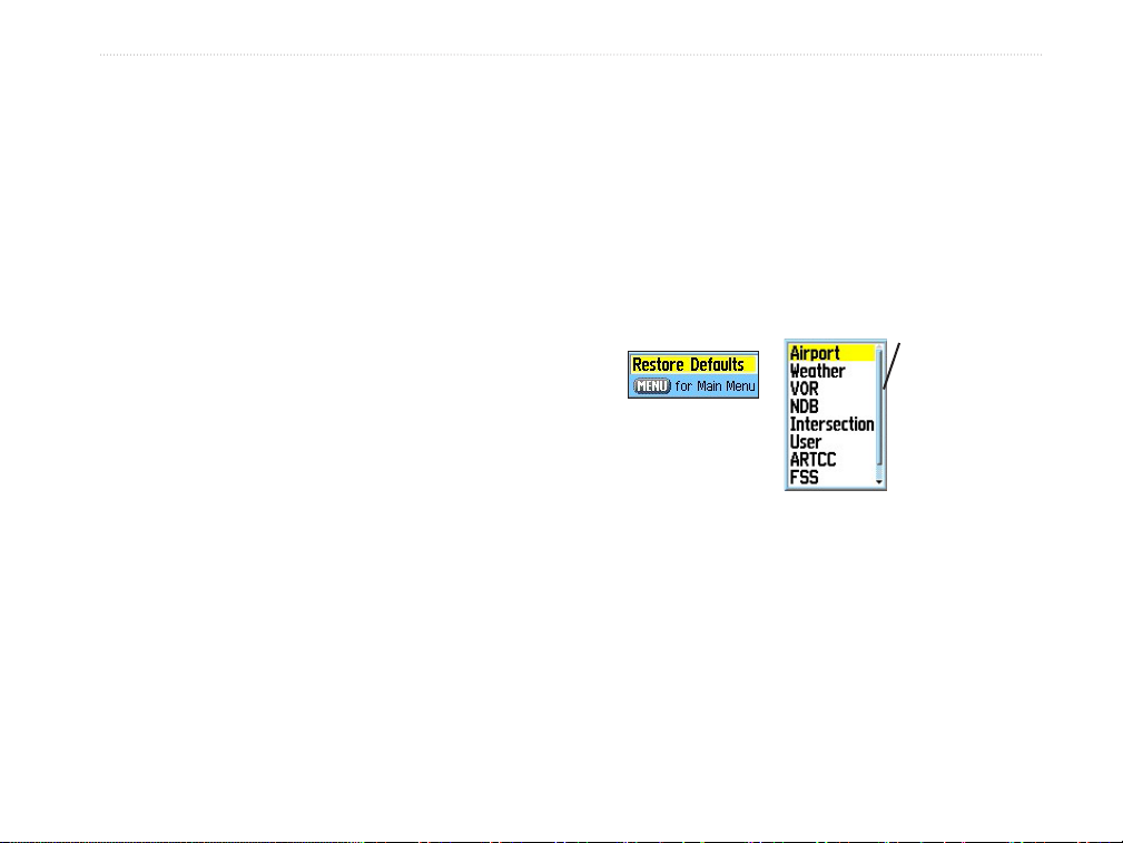
To nd an airport: (Aviation mode)
1. Press DIRECT TO D when in Aviation Mode
to show the Find Menu, select the Aviation
icon, then press ENTER or press DIRECT TO
when in Aviation Mode to show the Aviation Go
To Page.
Find More...
takes you to the
Find Menu with
references near
your
current location.
Add To Route - list of current saved routes.
Options Menu
Select one or create a new route.
Find Near Here
- takes you to
lists of map items
near the airport
identified by the
Aviation Go To
Page.
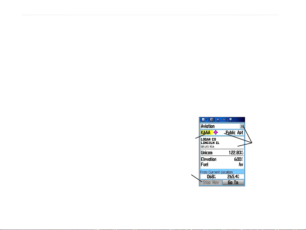
2. The Aviation Go To Page shows the rst airport
on the database list of airports, its location,
communication frequencies, elevation, type of
fuel available, and the direction and distance
from your current location.
Aviation Go To Page
3. To search for a specic airport, highlight the
airport eld, and use the ROCKER to enter the
identication letters of the airport. Then press
ENTER to highlight the Go To button.
4. Press ENTER to create a direct route to the
airport from your current location or QUIT to
exit the page.
96/96C Owner’s Manual 43
Page 52

BaSIc operatIon >
To use the Aviation Go To Page Options:
1. With the airport shown on the page, press
MENU to show the Options Menu.
2. Find More and Find Near Here take you to
the Find Menu. Show on Map shows the
airport on the map, Project Waypoint allows
you to project a new waypoint from that
location (see page 34), Set Proximity allows
you to set a proximity alarm for this location
(see page 36), and Add To Route allows to
place the airport in a route you are creating
(see page 22).
Searching for a Marine Point
The Find Marine Point feature allows you to search
for the marine items, such as marinas, navaids,
services, wrecks and obstructions. If using BlueChart
detailed marine chart data, the Tide Station feature
allows you to view tide predictions for locations
contained in the mapping data.
®
To nd a Tide Prediction Station
1. Press DIRECT TO D when in Automotive or
Marine mode to show the Find Menu.
2. Select the Marine Points icon, then press
ENTER to show the sub-icon(s) for marine
items supported by the basemap and
downloaded detailed marine charts.
3. Use the ROCKER to highlight and select the
Tide Station icon, then press ENTER.
44 96/96C Owner’s Manual
Page 53

4. A list of tide stations nearest to you appears. If
a “None Found” message appears, then you
are not currently located near a coast line.
Press MENU to show the Tide Station Options
Menu. Select from Nearest Containing or
Change Reference. You can enter a key word
for a known tide station or can use the map
pointer to move to the nearest coast line, and
then press ENTER to establish a location near
marine items.
5. Select a tide station from the list, and press
ENTER to show the information page for that
tide station.
At the bottom of the Information Page are on-screen
buttons for Go To, Map, and Save.
To nd a Wreck or Obstruction:
1. Select the Marine Points icon, and then
press ENTER to show the sub-icon(s) for
marine items supported by the basemap, and
downloaded detailed marine charts.
BaSIc operatIon >
Wrecks/Obstructions
2. Use the ROCKER to highlight and select the
Wrecks/Obstructions icon, then press ENTER.
3. If you get a “None Found” message, you are
too far from the coastline or out of the area of
map data coverage. Press MENU and use the
Change Reference option as explained on the
previous page.
4. Select an item from the list, and press ENTER
to show the information page for that item.
96/96C Owner’s Manual 45
Page 54

BaSIc operatIon >
At the bottom of the Information Page are on-screen
buttons for Go To, Map, and Save.
Marine Services List
To nd Marine Services
1. Follow the same procedure as above to
access the Marine Points Menu, and then
select the Marine Services icon.
2. If the “None Found” message appears, follow
the same steps explained previously to show
a list of marine services near the location you
have selected.
3. When the information page for a selected
service appears, you can highlight each
information category, and press ENTER to
show additional information.
Searching for an Address
The Find Addresses feature allows you to search
for an address within the coverage of downloaded
detailed mapping data. Enter the street number, and
street name and the Find Feature matches that data
with addresses in the map database.
To nd an Address: (Automotive or Marine
Modes)
1. Press DIRECT TO D to show the Find Menu.
2. Highlight the Addresses icon, and press
ENTER to show the Addresses page.
3. If your unit has a GPS x, the Region eld at
the top of the page shows your current region,
and the <Enter City> eld disappears. The city
shows with the list of address matches when
nished.
46 96/96C Owner’s Manual
Page 55

BaSIc operatIon >
4. Press MENU to show the options list. You can
choose a new region, clear all, or show a list
of regional cities if you want to search for a
city yourself. If you select Enable City Filter an
enter city eld shows on the Address Page.
Highlight the eld and press ENTER to show
the city list. Select a city from the list, and
press ENTER to insert the city
5. Next enter the Street Number <Enter
Number> using the ROCKER.
Find Address
Matches
6. Finally press ENTER to show the street list.
Use the ROCKER to enter enough of the
street name to show a match on the list below.
When nished, a list of matches appears
below. Select one, and press ENTER to show
the Information Page. Highlight the Go To
button to navigate to the address.
Searching for a Crossroad
The Find Crossroads feature allows you to search
for an street intersection within the coverage of
downloaded detailed mapping data. Enter the two
street names and the Find Feature matches that data
with intersections in the map database.
Crossroads Search Page
96/96C Owner’s Manual 47
Page 56

BaSIc operatIon >
To nd a Crossroad: (Automotive or
Marine Modes)
1. Press FIND to show the Find Menu.
2. Highlight the Crossroads icon, and press
ENTER to show the Find Crossroads search
page.
3. If your unit has acquired satellite signals, the
Region eld at the top of the page shows
your current region, and the <Enter City> eld
disappears. The city appears list of crossroad
matches when nished.
4. Press MENU to show the options list. You can
choose a new region, clear all, or show a list
of regional cities if you want to search for a
city yourself. If you select Enable City Filter
an enter city eld appears on the Crossroads
Page. Highlight the eld and press ENTER to
show the city list. Select a city from the list,
and press ENTER to insert the city
5. Highlight <Enter Street 1> and follow
instructions in step 6 on the previous page.
Repeat for <Enter Street 2>.
6. When done, a list of matches appears below.
Select one, and press ENTER to show the
Information Page. Highlight the Go To button
to navigate to the crossroad.
Searching for a Point of Interest
You can use the Find Point of Interest feature to locate
points of interest such as nearby restaurant, lodging,
landmark, public building, and parks. However, you
must have downloaded MapSource detailed mapping
that supports this feature otherwise these options, plus
Address and Crossroad options, are not available.
Find POI Topic List
48 96/96C Owner’s Manual
Page 57

BaSIc operatIon >
To nd a point of interest:
1. Press DIRECT TO D in Automotive or Marine
Modes to show the Find Menu or the Show
More option from the Aviation Go To Page.
Or
Select the Find icon from the Main Menu.
2. Highlight a Points of Interest icon, and press
ENTER to show the list of nearest points.
3. Press MENU to choose from search options
or choose Select Category to narrow your
search.
4. Highlight am item from the list, and then press
ENTER to show the Information Page for that
item.
Creating and Using a Route
Route navigation allows you to create a sequence of
intermediate waypoints which lead you to your nal
destination. The GPSMAP 96/96C stores 50 routes,
each with up to 250 waypoints each. A route can
be created and modied from the Routes Page, and
waypoints can be added to a route from the Aviation
Go To Page or Find Menu. More complex routes can
be created using a PC and MapSource programs and
then transferred to the unit memory.
If you are searching for a restaurant that is part of
a national chain, only the nearest restaurant to your
location is shown when you search using the “Find
Nearest” method. If you search using the “By Name”
method, then all of the locations for that chain in the
mapping database is shown with the closest to your
current location listed rst.
Indicates
Active
Route
Saved Routes List
96/96C Owner’s Manual 49
Page 58

BaSIc operatIon >
To create a route:
1. Access the Routes Page from the Main Menu.
2. Use the ROCKER to highlight the New button,
and press ENTER to show the route Setup
Page.
3. With an empty row (dashed) in the route list
highlighted, press ENTER to show the Aviation
Go To Page.
4. Use the Find Menu to select a route waypoint
from one of the Find Menu groups and shows
the Information Page for the selected point of
interest. Highlight the on-screen Use button,
and press ENTER to place it on the Route
Waypoint List.
5. To add more points to the route, repeat the
process.
6. Press QUIT to save it to the Saved Routes list.
Or
Press MENU, highlight Activate, and press
ENTER to navigate.
Methods of navigating to a destination:
• When you start the “Go To” button on the
Information Page for a User Waypoint or other Find
Menu item, the GPSMAP 96/96C creates a straight
path (point to point) from your current location to that
location.
4. Press MENU, select Find More..., and press
ENTER to show the Find Menu.
• When you select Activate from a Route Page
options menu the GPSMAP 96/96C creates a
route composed of several User Waypoints or Find
Menu items, with the last being your destination.
It navigates directly from point to point. Before
50 96/96C Owner’s Manual
Page 59

BaSIc operatIon >
each turn in the route a turn page shows a guidance
message and graphic of the turn. You can view the
turns at any time by pressing the ROCKER up or
down while the route is active.
• In Automotive Mode these two navigation methods
change when you select the “Follow Roads” option
from the Routing Setup Page. Both Go To navigation
and point to point routing become routes that allow
you to navigate using roads.
The routes use existing roadways (either those in
the basemap or from downloaded detail mapping) to
automatically calculate a route to your destination.
Turns on roadways are added to the active route page
and is preceded by a guidance message with a graphic
screen of the turn.
If there are not enough roads at your location to
calculate a route, a message appears.
Navigating a Route
After you have created a route, you can begin
navigation immediately or save it to the Saved Routes
list as explained on page 72.
When you are navigating a route, a guidance message
and graphic view of turns in the route shows as you
approach each one. Using the “Follow Roads” option
from the Routing Setup Page increases the number of
turns and shows an Active Route Page with a list of
turns. If you selected the “Off Road” option you can
view only the list of points for a route from the Active
Route Page. (See Routing Setup on page 107)
96/96C Owner’s Manual 51
Page 60

BaSIc operatIon >
To Preview the Turns for an Active Route:
1. From the Routes Page, highlight the route from
the Routes list.
2. Press ENTER to show the Route Page for the
route.
3. Highlight a route and from the Saved Routes
list, and press MENU to show the options
menu. Select Activate, and press ENTER to
begin navigation and to show the route on the
Map Page.
Active Route Page
4. To view the list of turns on the route, press
PAGE to show the Active Route Page. The
view any individual turn on the list, use the
ROCKER to highlight it, and press ENTER.
List of Turns for an Active Route
using the Follow Roads option
5. The Preview Page show the turn and guidance
text and a small eld at the bottom showing
the turn number in sequence and total turns in
the route. To scroll through all turn previews,
move the ROCKER up or down. To exit, press
QUIT.
6. To stop navigating, select Stop Navigation
from the Map or Pointer Page, and press
ENTER.
52 96/96C Owner’s Manual
Page 61

BaSIc operatIon >
Route Options (for all operating modes)
To start a route:
From the Saved Routes Page, press MENU to
show the Options Menu. Highlight the Active
Route option, and press ENTER.
To create a new route:
From the Saved Routes Page, press MENU
to show the Options Menu. Highlight the New
Route option, and press ENTER to show the
New Route Page
To copy a route:
Highlight the Copy Route option, and press
ENTER. The copied route show, and is named
the same but followed by a numeral 1.
Saved Routes Options
To delete a route or all routes:
1. From the Saved Routes Page, press MENU.
2. To clear a highlighted route or the saved routes
list, select Delete Route or Delete All Routes,
and press ENTER. A prompt shows, asking
“Do you really want to delete...?” Select Yes,
and press ENTER.
To set up the route leg transition for
routes:
1. From the Saved Routes Page, press MENU to
show the Options Menu.
2. Highlight the Set Up Routes option, and press
ENTER to show the Route Leg Transition Set
Up Page.
96/96C Owner’s Manual 53
Page 62

BaSIc operatIon >
3. Highlight the Route Leg Transition eld, and
press ENTER to show the list of options.
Select Auto, Manual, or Distance. These
settings control manner in which the route
advances to the next leg.
Using the Route Detail Page Options:
To start the route:
With the Options Menu shown, highlight
Activate, and press ENTER.
To edit the route on the map:
1. With the Options Menu shown, highlight the
Edit on Map option, and press ENTER to
show the route on the map. Use the ROCKER
to move the panning arrow to select a route
waypoint on the map.
2. Press
ENTER to show the options for editing
that waypoint. You can Review, Remove, or
move to the Next waypoint, and Add Turns by
creating new waypoints on the map.
Using the Route Detail Page Options:
To start the route:
With the Options Menu shown, highlight
Activate, and press ENTER.
Route Detail Page
54 96/96C Owner’s Manual
Page 63

BaSIc operatIon >
To edit the route on the map:
1. With the Options Menu shown, highlight the
Edit on Map option, and press ENTER to
show the route on the map. Use the ROCKER
to move the panning arrow to select a route
waypoint on the map.
2. Press ENTER to show the options for editing
that waypoint. You can Review, Remove,
move to the Next waypoint, and Add Turns by
creating new waypoints on the map.
To reverse the route:
With the Options Menu shown, highlight the
Reverse Route option, and press ENTER.
To select an approach: (Aviation Mode
only)
With the Options Menu shown, highlight Select
Approach to show options for the destination
airport.
To set speed and fuel ow:
With the Options Menu shown, select the Set
Speed and Fuel option, and press ENTER to
show the Set Fuel Flow option.
To modify a waypoint on a Route Detail
Page:
Select the waypoint from the list of waypoints,
and press ENTER to access the Route
Waypoint Options Menu. You can Review the
information page for the waypoint, Insert a
new waypoint ahead of the selected waypoint,
Remove the selected waypoint, Change it to
another waypoint, and Move it in the list order.
96/96C Owner’s Manual 55
Page 64

BaSIc operatIon >
VNAV PROFILE
GLIDE RATIO TO TARGET
DISTANCE TO TARGET
DISTANCE TO PROFILE
TARGET ALTITUDE
AIRPORT
VNAV (Vertical Navigation) Setup Page
The VNAV Page provides settings for the vertical
navigation feature. These settings create a three-
dimensional prole that guides you from your present
position and altitude to a nal (target) altitude at a
specied location. When dened, message alerts and
data track your progress on the HSI Page.
As you approach the initial descent point, the time
to vertical navigation eld (ETV) indicates the time
to reach the initial descent point. The “Approaching
VNAV Prole” message appears one minute prior to
the initial descent point. The descent angle locks to
prevent changes in speed from altering the prole.
The VNAV feature does not take into account
any changes in groundspeed that occur during the
A VNAV indicator
appears as
a moving bar
depicting the
Vertical Deviation
from the VNAV
Prole.
VNAV on HSI Page
NOTE: The GPSMAP 96/96C is a VFR
navigation tool and should not be used to
perform instrument approaches. VNAV is only a
VFR navigation instrument and is not intended
for instrument approaches.
56 96/96C Owner’s Manual
transition from level flight to descent or climb. The
“Approaching Target Altitude” message appears at
500 ft above the target altitude, the time to vertical
navigation goes blank, and the VNAV indicator
disappears from the HSI Page.
Page 65

Settings
Target Altitude—the altitude you want to be at
when you reach your target location. Select Above
Waypoint to use eld elevation for airports in the
Jeppesen database or “Above MSL” to specify an
exact MSL altitude target.
By—denes the target location with settings of
distance Before or After a reference waypoint
(normally the nal destination airport). To set a target
location AT a reference waypoint, enter a distance of
zero.
BaSIc operatIon >
VNAV Setup Page
VNAV Waypoint—allows you to select any waypoint
along the currently active route (or Go To) as your
reference waypoint. The reference waypoint denes
the target location.
VNAV Prole—allows you to select the descent rate.
VNAV Messages—enables and disables the VNAV
alert messages.
96/96C Owner’s Manual 57
To dene the VNAV prole settings:
1. Press MENU twice to show the Main Menu.
Use the ROCKER to select Setup, and then
VNAV.
2. Use the ROCKER and ENTER keys to
highlight and select options.
To Restore Defaults:
While on the VNAV Page, press MENU. A
message “Restore Defaults” appears. Press
ENTER.
Page 66

MaIn paGeS >
MaIn paGes
Aviation Mode features ve main pages: Satellite
Page, Position Page, Map Page, HSI Page and Active
The GPSMAP 96/96C offers three usage modes,
Aviation Mode (default), Marine Mode, and
Automotive Mode, allowing you to customize settings
to use the unit for each application. The modes can
be changed in the System Setup option or by pressing
and holding PAGE. The main pages are linked
together in a series that you can cycle through by
pressing PAGE to go forward and QUIT to reverse.
Each page also has an Options Menu that allows
you to customize each (in all three modes) to your
preferences and select features that relate to that page.
To view the Options Menu for a page, press MENU.
Satellite Page
58 96/96C Owner’s Manual
Position Page
Map Page
Route/Go To Page. An example of each page in
Aviation Mode appears below. Each of these pages
has a specic use and each page is discussed later in
this manual. The Aviation Mode is the default mode
for the GPSMAP 96/96C. This guide rst addresses
each page, such as the Map Page, as shown in the
Aviation Mode. The guide then describes the page
shown in Marine and Automotive Mode, if major
differences exist.Marine Mode features ve main
pages: the Satellite, Position, Map, Pointer, and
Active Route Pages. The Active Route Page appears
with a list of route waypoints if you are navigating.
HSI Page
Active Route/
Go To Page
Highway Page
(Automotive Mode)
Page 67

MaIn paGeS >
See the Navigation section for more information on
navigation options. Automotive Mode features the
same ve pages as Marine Mode with the exception
that the Active Route Page provides instructions when
auto-routing is being used. When you are following
roads to your destination, the Active Route Page
changes from a list of waypoints to a graphic of each
turn on your route with a turn detail page to support
each turn on the active route. An optional Highway
Page can be enabled in all modes.
The Map Page
The GPSMAP 96/96C features a real-time moving
map that can do much more than just plot your
course. The Map Page shows digital cartography
(map information) that includes airspace boundaries,
airports, navaids, lakes, rivers, coastlines, cities and
highways. An on-screen pointer (Panning) arrow lets
you pan ahead to other map areas, determine distance
and bearing to any map position, and retrieve database
information directly from the map. Dedicated zoom
keys (IN and OUT) are provided for instant scale
adjustments.
Two basic map operating modes, position mode and
cursor mode, determine what cartography is shown on
the Map Page. Position mode pans the cartography.
The position marker (position icon) that shows your
travel on the Map Page is an aircraft symbol in
Aviation Mode or a position symbol in Marine or
Automotive modes. The GPSMAP 96/96C always
powers up in the position mode, with the last known
location centered on the map screen.
96/96C Owner’s Manual 59
Page 68

MaIn paGeS >
select Map Only without data elds, using the Map
Page Options Menu.
Panning the Map with the Pointer Arrow
The Pointer Arrow allows you to pan away from
your present position and scroll to other map areas
Marine Mode
Options
Map Page
When you press the ROCKER, the GPSMAP 96/96C
enters cursor mode that pans the cartography to keep
the cursor, the white pointer (panning) arrow icon
, within the screen. When the cursor is active, an
additional data window appears at the top of the
screen to indicate the position, range, and bearing to
the cursor or a selected waypoint or map item.
around the world (even outside of your current detail
coverage). As you pan past the edge of the current
map screen, the screen actively scrolls to provide
continuous map coverage (keep in mind that the
position icon stays in your present location and can
not be visible on the screen when you pan the map).
Position Data
Window
GPS Status
Up to four user-selectable data elds can be selected
to appear on the screen. From the Map Page Options,
each data eld can be congured to show any one of
the possible data options. You can also add an HSI
eld which replaces two data elds on the page or
60 96/96C Owner’s Manual
Description
of map point
from the map
database
Pointer (Panning)
Arrow
Map Page in
Panning Mode
Page 69

MaIn paGeS >
To move the arrow:
Press up, down, right or left on the ROCKER.
As you move the Arrow, the distance and bearing
from your present position to the cursor shown in the
data window. When you zoom in panning mode, the
arrow stays centered on the screen. When the arrow is
stationary, a xed coordinate position appears in the
position eld, and the distance and bearing from your
present position changes as your vehicle moves.
To re-center your position on screen:
1. When you are nished panning the Map, press
QUIT.
2. The unit automatically returns to position
mode.
The arrow can also be used to snap to on-screen
waypoints and map items, allowing you to review
a selected position or feature directly from the map
screen.
To select an on-screen waypoint or map
item with the arrow:
1. Use the ROCKER to move the arrow to a
waypoint or map item. If there are several
items grouped closely together, zoom in closer.
2. When a waypoint or map item is selected,
it is highlighted on screen with the name
and position shown at the top of the screen,
along with the distance and bearing from your
current location.
Map Page in Panning
Mode with a map item
highlighted.
96/96C Owner’s Manual 61
Page 70

MaIn paGeS >
To view additional details about an onscreen waypoint or map item:
1. With the waypoint or map item highlighted,
press ENTER.
2. If the item is a waypoint, a Waypoint
Information Page appears, showing details
such as name, symbol, coordinates, elevation,
and depth. The on-screen buttons Delete,
Map, or Go To appear. Select an on-screen
button and press ENTER, or press QUIT to
exit the Waypoint Information Page.
If the item is a map feature, an Information
Page appears, showing details about the
feature. The on-screen buttons Delete, Map,
or Go To appear. Select an on-screen button
and press ENTER, or press QUIT to exit the
Waypoint Information Page.
Airspace Information
The Panning mode can also be used to retrieve
information on airspaces depicted on the map. Once
the Pointer Arrow is placed on an open area within
an airspace, the entire airspace (or airspace sector) is
highlighted. A text box adjacent to the arrow indicates
the airspace type and floor/ceiling limits. Additional
information, including communication frequencies, is
available from an information page.
Airport Information Page
62 96/96C Owner’s Manual
Page 71

To retrieve airspace information from the
Map Page:
1. Use the ROCKER to select an open area
within the airspace’s boundary. The boundary
line is highlighted and a window appears
showing airspace type and oor/ceiling limits.
2. To show additional information, press ENTER.
Communication frequencies can be shown by
highlighting the on-screen Frequencies button
and pressing ENTER.
3. To return the to Map Page, highlight OK, and
press ENTER.
Using the built-in
The system has a built-in worldwide database to 20
mi, with more detailed coverage available through the
use of the optional MapSource data. The GPSMAP
96/96C shows cartography as long as there is mapping
information available for the range you have selected.
Map coverage conforms to the following conditions:
basemaps
Using MapSource
downloaded detailed
mapping data
MaIn paGeS >
Overzoom
No additional
data available
Selecting Map Scales and Additional
Maps
The map screen has 28 available range scales from
20 ft. to 800 nm. (20 ft. to 800 mi or 5 m to 1200
km). The map zoom range is controlled by the IN and
OUT keys. The current scale is shown at the bottom
left of the map screen.
To select a map scale (zoom in and out):
Press the OUT key to zoom out and the IN key
to zoom in.
96/96C Owner’s Manual 63
• Cartography is shown when the selected zoom
range is covered by either the internal basemap
or other MapSource data downloaded to the
unit.
• When the selected zoom range is covered
by both the internal bundled database and
downloaded MapSource detailed mapping
information, the cartography with the best
resolution is shown.
Page 72

MaIn paGeS >
• When the selected zoom range exceeds the
resolution of the data in use, an “overzoom”
warning appears below the map scale.
• When mapping data, downloaded from
MapSource, is used, a MapSource indentier
appears below the zoom scale indicator.
Map Page Options Menu
The Options Menu on the Map Page provides access
to functions and features of the Map Page, as well
as layout options for the page. Each data eld can be
congured to show any one of several data options.
In the sections following, options have instructions
on how to use the option. The Options Menu varies
slightly between the Usage Modes.
•
Stop Navigation—turns off active route
navigation.
Recalculate—recalculates any active route.
•
Declutter On/Off—toggles between showing
•
map detail or simply map outlines for easier
viewing.
Set Up Page Layout—allows you to customize
•
the layout of the page, such as the size of text
and number of data elds.
To show the Map Page Options Menu:
From the Map Page press MENU to show the
options menu.
Show/Hide Guidance Text—(Automotive
•
Mode only) toggles between showing or hiding
the directions eld at the top of the Map Page.
Hiding the directions enables more of the map
to be visible.
Set Up Map—jumps to the Map Setup Menu,
•
allowing you to congure the Map Page to
your preferences, including map detail, map
orientation, automatic zoom, and various map
Aviation Mode
64 96/96C Owner’s Manual
items and points. See page 74.
Page 73

MaIn paGeS >
• Set Up Obstacles—jumps to Obstacle Setup
Page allowing you to congure obstacle alert
You can adjust the level of declutter by pressing
ENTER repeatedly.
settings.
Change Data Fields—allows you to specify
•
the type of data shown in each data eld on
the page. Refer to the Appendix for a complete
descriptions of all data elds used in the
GPSMAP 96/96C.
Measure Distance—allows you to measure
•
the bearing/distance between two points on the
map.
To declutter the Map Page:
1. Press Page repeatedly until the Map Page is
shown.
2. Press MENU.
3. Use the ROCKER to highlight Declutter, and
press ENTER.
To declutter the Map Page in Aviation
Mode:
1. Press PAGE repeatedly until the Map Page is
shown.
2. Press MENU.
3. Use the ROCKER to highlight Declutter, and
press ENTER.
The rst level shown after you press ENTER
is identied by Clear -1 under the map zoom
range. The background map detail—including
highways, cities, rivers & smaller lakes—is
removed from the map screen.
4. Press ENTER again. Airspace boundary detail
is removed from the map screen. CLEAR-2
appears below the map zoom range.
5. Press ENTER again. Only the waypoints and
navaids that are part of the current Go To or
route appear on the map screen. CLEAR-3
appears below the map zoom range.
6. Press ENTER again to return ALL detail to the
map zoom range.
96/96C Owner’s Manual 65
Page 74

MaIn paGeS >
To measure the Bearing/Distance between
two points:
1. Highlight the Measure Distance, and press
ENTER. An on-screen pointer appears on the
map screen at your present position with ENT
REF below it.
Measure Distance
2. Move the cursor to a reference point (the
starting point that you want to measure from),
and press ENTER. A push-pin icon marks the
starting point on the map screen.
Refer to the Appendix for a detailed description of
each data option.
3. Move the cursor to the point to which you want
to measure. The bearing and distance from
the reference point and cursor coordinates
are shown in the data window at the top of the
screen.
4. Press QUIT to nish.
To set up the page layout:
1. Highlight Set Up Page Layout from the
Options Menu, and press ENTER.
2. Select an option, and press ENTER. The
options vary between the three usage modes.
To change a data elds:
1. From the Options Menu, highlight Change
Data Fields, and press ENTER.
2. Move the eld highlight to the data eld you
want to change, and press ENTER.
3. Press up or down on the ROCKER to highlight
the data you want to show, and press ENTER.
4. Press QUIT to exit.
66 96/96C Owner’s Manual
Page 75

MaIn paGeS >
The HSI Page
The HSI (Horizontal Situation Indicator) Page
replaces the Pointer Page when the unit is in Aviation
Mode. During active navigation, the HSI Page guides
you to your destination with digital data eld readouts
and a graphic pointer with a bearing pointer.
current ground track, off course error and a To/From
indicator. The rotating compass ring indicates your
current ground track (read at the top of the ring). The
course pointer or course deviation pointer indicate the
your course and the distance you are off-course. A bug
indicator provides course to steer information, guiding
you to the destination if you are off-course.
Data Fields
The course deviation scale appears behind the course
deviation pointer. If you stray off-course, the pointer
Compass Ring
To/From Indicator
indicates how far off-course you are. To get back oncourse, steer toward the pointer. The course deviation
Bug Indicator
Course
Pointer
HSI Page
CDI Scale
scale is adjustable for .25, 1.25, or 5.0 (nautical
mile/statute mile/kilometer) full scale deflection. The
default setting is 1.25. This is adjusted using the IN
and OUT keys.
As you reach your destination, the To/From Indicator
at the center of the HSI indicates waypoint passage.
To show the HSI Page in Aviation Mode:
While in Aviation Mode, use PAGE to show the
HSI Page.
The graphic on the HSI Page depicts the course to
your destination (or to the next waypoint in a route),
The four data elds at the top of the page are user
congurable by accessing the Change Data Fields
option from the HSI Page Options Menu. For
denitions of available data eld options refer to the
Appendix.
96/96C Owner’s Manual 67
Page 76

MaIn paGeS >
The Pointer Page
The Pointer Page replaces the HSI Page when the
unit is in Marine or Automotive Mode. During active
navigation, the Pointer Page guides you to your
destination with digital data eld readouts and a
graphic Pointer appears with a bearing pointer.
The direction of your destination (bearing) relative
to the course is indicated by a bearing pointer in
the middle of the Pointer ring. A bearing “bug”
on the outside of the Pointer ring in Marine mode
only. The Pointer ring and bearing indicators work
independently to show, at a glance, the direction of
your movement and the direction to your destination.
To show the Pointer Page in Marine and
Automotive Modes:
While in Automotive or Marine Mode, use
PAGE to show the Pointer Page.
If the arrow points up, you are going directly to the
waypoint. If the arrow points any other direction turn
toward the arrow until it points up. The Marine Mode
is a Course Pointer similar to the HSI, that can be
selected from the Marine Mode Options Menu.
NOTE: You must be moving for the Pointer to
accurately update and show your heading.
Congurable data elds at the top of the page show
helpful information during active navigation. For
denitions of data eld settings, refer to the Appendix.
Pointer Page (Automotive Mode)
The bottom of the page features a rotating Pointer ring
that shows your course over ground (track) while you
The Automotive Mode features data elds with
default settings that are more desirable for land
navigation.
are moving. The course is indicated at the top of the
Pointer ring.
68 96/96C Owner’s Manual
Page 77

HSI/Pointer Page Options Menus
The Options Menu on the Pointer Page allows you to
customize the HSI/Pointer Page to your preferences
in all unit operating modes. Like the Map Page, the
HSI/Pointer Page features user-selectable data elds.
Each data eld can be congured to show any one of
several data options, and the data window layout can
be customized to change the actual size of the data
shown.
To show the HSI/Pointer Page Options
Menus:
1. Press MENU to show the Options Menu.
2. Use the ROCKER to select an option.
The options available on the HSI/Pointer Page
Options Menus are:
Stop Navigation/Resume Navigation—(Automotive
and Marine modes)
Recalculate—(Automotive and Marine Modes) Use
for an active route.
Set OBS and Hold—(Aviation Mode) Allows you to
alter your course.
MaIn paGeS >
HSI Page Options
(Aviation Mode)
96/96C Owner’s Manual 69
Page 78

MaIn paGeS >
Set CDI Scale—(Aviation and Marine Modes)
Adjusts the CDI scale.
Set Bug Indicator—(Aviation and Marine Modes)
Sets the Bug Indicator mode.
Enable/Disable VNAV Indicator—(Aviation Mode)
Bearing Pointer/Course Pointer—(Marine Mode)
Toggles between the Bearing Pointer and the Course
Pointer. The Course Pointer, which shows how far off
you are from your course and how to get on course.
Also referred to as a CDI, Course Deviation Indicator.
Set Up VNAV—(Aviation Mode) takes you to the
VNAV setup page.
Set Up Page Layout—allows you to choose text size
and number of data elds.
Change Data Fields—allows you to specify the type
of data shown in each data eld on the page. Refer to
the Appendix for data descriptions.
Active Route Page
Whenever you have started a route while in Aviation
or Marine Mode, the Active Route Page shows each
point (waypoint or map item) of the active route, with
the point name, Course, Distance, and several other
elds of information. The current destination point,
the “active” point, is marked with an arrow icon. As
you navigate a route, the list automatically updates to
indicate the next “active” point rst. The Active Route
and Route Review Pages share many of the same
features and options.
Whenever you have started a route in the GPSMAP
96/96C set in Automotive Mode, the Active Route
Page shows each turn of the active route, with the
distance to the turn, the street name, and estimated
time to arrival and time of arrival. As you navigate a
route, the turn list automatically updates to indicate
the next turn at the top of the list.
70 96/96C Owner’s Manual
Page 79

The Active Route Page becomes an Active Go
To Page when navigating to a destination with no
waypoints in between you and the destination.
Active Route Page
You can scroll through the entire list by moving the
scroll bar up or down. Highlight any of the turns on
the list, and press ENTER to view the Next Turn page
for that turn. The Current Route and Next Turn page
show similar information, just in a different layout.
The Next Turn page shows your next turn on a map.
For additional details on the Active Route Page, see
the “Creating and Using a Route” page 49 section of
the “Basic Operation” chapter.
MaIn paGeS >
Active GoTo
(Aviation Mode)
96/96C Owner’s Manual 71
Page 80

MaIn paGeS >
Active Route Page Options Menu
The following route options are available by pressing
Menu.
x (FAF) to missed approach point (MAP), and are
based on existing GPS, RNAV, VOR, NDB, localizer,
or ILS approach procedures. All approach procedures
are flown as a sequence of waypoints in the route. In
order to select an approach and add the waypoints
to the route, the nal destination in the “Go To” or
“Route” must be an airport with a published approach.
Set Fuel Flow—allows you to enter fuel consumption
rate and distance. Intended for use in the Aviation
Active Route
Options Menu
Deactivate—stops route navigation.
Edit on Map—allows you to edit the route on the
map.
Reverse Route—reverses the order of the route.
Select Approach—(Aviation Only) allows you
to select the nal course segment of a published
approach, replacing the nal destination airport (in a
Go To or route) with the sequence of waypoints for
Mode, but can be applied to other modes.
Change Data Fields—allows you to customize the
data elds shown on the Active Route Page.
Saving the Active Route
You can save the current route from the Current
Route Page. Press Menu to save the route. Press
ENTER when Save Route is highlighted. Your route
is automatically saved, using the starting point and
destination as the route name. Press ENTER when
OK is highlighted to complete saving the route.
the selected approach. The approaches provide only
the nal course segment, usually from nal approach
72 96/96C Owner’s Manual
Page 81

MaIn paGeS >
Position Data Page
The Position Data Page provides a quick reference for
the important data you want to show while navigating
a route in Aviation Mode and Marine Mode. The
default page shown six user-selectable data elds.
The two elds at the bottom of the page shown
location position coordinates and the nearest airport,
city, or other map features depending on the mode of
operation.
Position Data Page Options Menu
The following options are available from the Position
Data Page:
Position Page Options Menu
Reset—allows you to see the “Reset” page. See the
following page for reset options.
Big Numbers—allows you to change the data elds
to show fewer data elds with larger numbers for
easier viewing.
Change Data Fields—allows you to specify the type
of data shown in each data eld. See the Appendix for
a listing of the data elds.
Change Nearest Type—allows you to specify the
type of item to be used as the nearest item. The
choices differ based upon the Usage Mode you are
currently using.
Position Page Reset Menu
The following options are available from the Position
Page Reset Menu. Some options are only available if
you have changed the Page Layout from the default
(shown to the right).
Reset Trip Data—clears trip information, except the
maximum speed and the odometer.
Reset Odometer—clears the running total of the
distance traveled since the odometer was last reset
96/96C Owner’s Manual 73
Page 82

MaIn paGeS >
Reset Max Speed—clears the maximum speed.
Clear Track Log—clears the track log.
Delete Saved Tracks—deletes all saved tracks.
Delete All Waypoints—deletes all waypoints.
Delete All Routes—deletes all routes.
Position Page
Reset Page
The Map Setup Page
The Map Page for your GPSMAP 96/96C can be
customized. A factory set of default settings currently
controls the Map Page screen. The Map Setup Pages
allow you to determine how map features appear on
the page by controlling map orientation, text size,
track, map item, detailed map data, and more. It is
suggested that you wait until you are more familiar
with the operation of your unit before deciding what
features you want to customize.
Map Setup Page
74 96/96C Owner’s Manual
Page 83

MaIn paGeS >
To customize the Map Page:
1. To access the Map Setup Pages, press MENU
with the Map Page on the screen.
2. Scroll down the Menu to the Setup Map
option, and press ENTER to show the Map
Setup Page. At the top of the page are icons
for each setup page.
3. Use the ROCKER to move from icon to icon
when selecting a map setup page and to move
up and down to the feature elds on each
page.
4. With a Map Setup feature highlighted, press
ENTER to show the list of options for that
feature. Each Map Setup Page has a menu of
general options. This menu can be accessed
by pressing MENU with the page shown.
General Setup
The rst page of the Map Setup feature is the
General Settings Page. Use this page: to select the
map orientation, North Up (with north at the top of
the map) or Track Up (with the map oriented in the
direction of travel). Below sets the map zoom range
at which the Track Up feature shows, all scales above
that revert to the North Up map orientation. Auto
Zoom, zooms in on the map to include the beginning
and ending points of a route. Detail selects the degree
of map detail shown. You can lock the Position
Arrow to show on the nearest road, compensating for
variances in map position accuracy.
The General Settings Map Setup Page
96/96C Owner’s Manual 75
Page 84

MaIn paGeS >
Aviation Setup
The Aviation Settings Page allows you to turn On or
Off the Aviation, Land and Obstacle data and set the
radius of proximity circles.
Map Information Setup
The Aviation Settings Map Setup Page
Tracks Setup
The Tracks Settings Page has settings for maximum
zoom for viewing saved tracks and active track logs.
You can set the number of track points for recording
a track, select either a bearing or course line for
navigating a track and set the heading line to off and
to show in distance or time.
The Map Information Page show a list of downloaded
detailed MapSource® maps such as topographic,
marine charts and maps with auto-routing capability.
Use the ROCKER to highlight a map and press
ENTER to show it on the map screen or turn it off.
The Tracks Settings Map Setup Page
76 96/96C Owner’s Manual
Page 85

MaIn paGeS >
Pressing MENU shows list of options for managing
maps.
Points—Text Setup
Use the Map Points—Text Page to select the text size
for descriptions of items on the Map Page. You can
select from Small, Medium, or Large.
The Map
Information Map
Map Information
Options Menu
Setup Page
Points—Zoom Setup
The Map Points—Zoom Page allows you determine
the map zoom range at which various map features
appear. You turn off the screen, set it to Auto or select
a value from 20 feet to 500 miles.
The Points- Zoom Map Setup Page
SUAs Setup
The SUA’s Page of the map setup feature allows you
determine the map scale at which various Special Use
Airspace areas shown. You can turn off the screen, set
it to Auto or select a value from 20 feet to 500 miles.
The Points—Text Map Setup Page
96/96C Owner’s Manual 77
Page 86

MaIn paGeS >
Airport—Text Setup
The Airport—Text Page of the map setup feature
allows to select the text size for descriptions of
airports and runways on the Map Page. You can select
from Small, Medium, or Large.
The SUA’s Map Setup Page
Airport—Zoom Setup
The Airport Zoom Page of the map setup feature
allows you determine the map zoom range at which
various airports and runway features shown. You can
turn off the screen, set it to Auto or select a value from
20 feet to 500 miles.
Aviation Navigation—Zoom Setup
Use the Avtn Nav—Zoom Page to determine the map
scale at which various aviation navigation features
shown. You can set it to Auto or select a value from
20 feet to 500 miles.
The Airport—Text Map Setup Page
The Airport - Zoom Map Setup Page
78 96/96C Owner’s Manual
The Aviation Navigation—Zoom Setup
Page 87

MaIn paGeS >
Aviation Navigation—Text Setup
Use the Avtn Nav—Text Page to select the text size
for descriptions of aviation navigation features on the
Map Page. You can select from Small, Medium, or
Large.
Obstacle Data
Obstacle on the map Page are shown in red, yellow,
and gray and dark gray, light gray, and white for
the GPSMAP 96C and GPSMAP 96 respectively.
References to obstacle icon gray tones for GPSMAP
96 units are in parentheses for this section. Standard
aeronautical chart symbols are used for lighted or
unlighted obstacles above and below 1000 ft Above
Ground Level (AGL). Upcoming obstacles, as you
The Aviation Navigation—Text Map
Marine Setup
approach them, are marked by an “X” symbol.
Lighted Obstruction 1000 ft. AGL and higher.
The Marine Settings Page is used to control the screen
of marine chart items when using downloaded marine
charts (i.e. MapSource BlueChart® marine mapping
data).
The Marine Settings Map Setup Page
Obstacles appearing in red (dark gray) are predicted
Unlighted Obstruction 1000 ft AGL and higher.
Lighted Obstruction below 1000 ft AGL .
Unlighted Obstruction below 1000 ft AGL.
Obstacle Icons
to be within 100 ft elevation of your flight path. Those
colored yellow (light gray) are more than 100 ft, but
less than the elevation in the user dened “Caution
96/96C Owner’s Manual 79
Page 88

MaIn paGeS >
Elevation” eld below your flight path. You can
change the Caution Elevation from the default of 1000
ft to 750 ft or 500 ft. Obstacles below your currently
selected caution elevation threshold are shown in gray
(white).
Obstacle warnings are dependent upon the user
dened parameters on the Obstacle Data Setup. The
GPSMAP 96/96C evaluates obstacles, according to
the parameters set, within a proximately one mile
on either side of your projected flight path. Obstacle
warnings appear in either red with white lettering
(black with white lettering) indicating a red (dark
gray) obstacle is in range or black with white lettering
(white with black lettering) indicating a yellow (light
gray) obstacle. The obstacle warning remains on the
screen until the flight path has cleared the obstacle or
you have pressed Enter.
The GPSMAP 96/96C “Look Ahead Time” for
obstacles determines the maximum time frame when
an annunciation (a pop up window with tone) occurs.
The default setting is 120 Seconds, however you have
the option in the Obstacle Data Setup for 90 or 60
Seconds.
“Obstacle Alert Sensitivity” determines what level
Obstacle Warning
of alerts are annunciated. The GPSMAP 96/96C
defaults to high sensitivity, which annunciate all red
(dark gray) and yellow (light gray) obstacles at the
look ahead time set. The Obstacle Data Setup allows
you the option of high, medium, or low. Medium
sensitivity annunciates all of the red (dark gray) and
80 96/96C Owner’s Manual
Page 89

MaIn paGeS >
the highest priority of yellow (light gray) obstacles,
where low only annunciates red (dark gray) obstacles.
Obstacle Data Setup Page
Obstacle Data Setup
The Obstacle Data Setup Page allows you to set the
levels for alerting you to obstacles in or near your
flight path. This setup page can also be accessed from
the Map Page Options Menu.
To setup obstacle data:
1. Access the Obstacle Data Setup Page.
2. Highlight the rst eld, and press ENTER to
show the options for setting the minimum
difference in elevation for upcoming obstacles
contained in the mapping database.
3. Use the second eld to set the “Look Ahead
Time.” The time before reaching the obstacle.
4. The third eld is used to determine the
alert sensitivity threshold for the size of the
obstacle.
5. Use the ROCKER to select options, and press
ENTER.
96/96C Owner’s Manual 81
Page 90

MaIn paGeS >
The Highway Page
When you are navigating a route, the Highway Page
can guide you to the destination using data elds and
a graphic highway. Up to four user-selectable data
elds show information such as speed, distance,or
time to next point on the route. The list of data to
Your course is represented by a center line down the
middle of the graphic. As you move toward each point
on your route, the graphic shows the direction you
should move to stay on course to the point. Five scale
settings allow you to zoom in or out on the highway.
To navigate using the Highway Page:
show and the method of selection is the same as for
the HSI/Pointer Page and is explained in detail on
page 67.
Highway Page with
an Active Route
The Highway graphic provides visual guidance,
taking you point by point to your nal destination.
82 96/96C Owner’s Manual
1. While navigating, access the Highway Page
from the Main Menu and observe your path of
travel shown on the highway graphic.
2. Press MENU to show the options menu. You
can do the following:
Set Up Page Layout allows you to congure
data elds from four to three. Change the Data
Fields allows you to select the type of data
to show in each eld. Refer to page 66 for
instructions on changing data elds. To restore
defaults for the data elds press MENU with a
data eld highlighted and the press ENTER.
To show the Highway Page:
1. Press MENU twice to show the Main Menu.
2. Use the ROCKER to highlight the “Highway
Page” icon and press ENTER. This page can
be shown for all three operating modes.
Page 91

MaIn Menu >
MaIn Menu
The Main Menu is the directory for all unit features
not in the Main Page sequence with the exception
of Mark Waypoint, which is accessed by pressing
ENTER. The Time and Date can be found at
the bottom of this page. A detailed discussion of
each of the Main Menu features follows this brief
introduction. Use the ROCKER to highlight a feature
name and then press ENTER to show the feature
page.
Main Menu
• Find—This feature provides a convenient
method for searching for cities, airports.
Tracks—This feature allows you to maintain a
•
record of your movements (track log).
Routes—Create a list of points that you wish to
•
navigate to and save for later use.
E6B—Calculates winds aloft, density altitude,
•
and true airspeed based on entered data.
Flights—Shows a log of the flights you have
•
taken using the GPSMAP 96/96C.
Timers—Allow for timing in flight functions,
•
such as flights and batteries.
Aircraft—Allows you to enter custom
•
information about your aircraft.
Setup—Controls the settings for many of the
•
unit operating system features.
Proximity—An Alarm feature for a dened
•
circle around a specied waypoint.
Calendar—A calendar with data access as well
•
as waypoint association.
96/96C Owner’s Manual 83
Page 92

MaIn Menu >
• Alarm Clock—This feature allows you to use
the GPSMAP 96/96C as an Alarm Clock.
Nav/Sonar Alarms—This feature allows you
•
to select from a variety of navigation alarms for
aviation and maritime use.
Calculator—A standard or scientic calculator
•
for measurement conversions, etc.
Stopwatch—A multi-featured stopwatch.
•
Sun & Moon—Sunrise and sunset times, moon
•
phases and sun and moon location for any given
date and time.
Hunt & Fish—A table of time frames for best
•
hunting and shing opportunities for any given
location and date.
Message Log—Allows you to view a list of
•
messages received. This feature also includes
lters to exclude messages by type.
Highway—A useful graphic perspective with
•
congurable data elds for navigating a route.
Find
The Find Feature provides you with a method for
searching for Waypoints, Airports, Cities, and Exits
which are included in the GPSMAP 96/96C basemap
and Jeppesen database. You can also nd a Waypoint
you have saved. If you have downloaded Garmin
MapSource® mapping data that contains additional
map detail, you can search for and nd Points of
Interest, Addresses and Intersections. If you download
BlueChart® data, you can nd Marine Points such
as Wrecks and Obstructions, NAVAIDS, and
Anchorages. If this additional data is not loaded, these
options are not available.
Options
Menu for
Waypoints
Find Menu
84 96/96C Owner’s Manual
Page 93

MaIn Menu >
Searching for a map item is simplied by separating
the map database into groups which are shown as
icons on the Find Menu Page.
• When you access a Find group list, by default
Searching for a Location
If you know the name of the location you want to nd,
the Find By Name search option can be the easiest
method of searching.
it contains only those items near your current
location or the Panning Arrow (if active).
• To save effort in searching again for an item
already found, you can use the “Recent Finds”
group which contains a list of 50 last found
items of all categories. Pressing and holding
DIRECT TO key also shows this category at
any time when in Automotive or Marine Mode.
The options menu for each map item group offers its
own unique search options such as “Find By Name,”
“Find Nearest,” “Select Symbol” (for Waypoints),
“Change Reference” (by moving the map Panning
Arrow to a new location), “Nearest Containing” (a
key word you enter), “Select Category” (for those
groups such as Food and Drink, Lodging, etc.). Using
these options can effectively shorten your search.
96/96C Owner’s Manual 85
Page 94

MaIn Menu >
To nd a location using Find By Name:
1. Press DIRECT TO D to show the Find Menu.
2. Use the ROCKER to highlight the icon for the
type of item you want to search for, and press
ENTER to show the page.
Or
If you want to search the entire item database,
select All Points of Interest.
3. Press MENU to select Find By Name.
4. Use the ROCKER and ENTER keys to enter
the name of the location, when the list shows a
match, highlight OK and press ENTER to go a
list where you can select the item.
5. With the item selected, press ENTER to shows
the Information Page for that item.
Using the Find Item Information Page
When you have selected a Find item and pressed
ENTER, an Information Page shown with detailed
information about the item. This page contains:
Recent Finds
The Recent Finds Page saves all of your most recent
searches on a list that places your last found location
at the top of the list. When you exceed the number of
entries the list can hold, the oldest is deleted.
To return to a recently found item:
1. With the Find Menu shown, use the ROCKER
to highlight the Recent Finds icon, and press
ENTER to show the Recent Finds List.
2. Use the ROCKER to select the list item you
want view, and press ENTER to show the
Information Page for that item.
• A title (if a waypoint, it can be renamed and a
map symbol assigned)
• An information eld (if a waypoint,
information you add, if a map item, an address
or other description)
• Location coordinates, if the item is a waypoint.
• Elevation and depth if a waypoint.
• Direction and distance from current location or
the map pointer
86 96/96C Owner’s Manual
Page 95

MaIn Menu >
At the bottom of the page are three on-screen buttons,
• If selecting an item to add to a list of points,
these buttons appear differently depending on whether
you are selecting a Find item to navigate to or adding
a Find item to a route list as a waypoint.
Save–save as a waypoint.
Map–show on the Map Page.
Use–insert into a list of points on a route.
Selected as a
destination
Information Page for a Waypoint
• If selecting an item as a destination, the three
buttons appear as:
Save/Delete—Add to or Remove from the
Waypoints list.
Map—show on the Map Page.
Go To—start a Go To navigation.
these three buttons appear.
Selected as
a Point on
a Route or
Track
Information Page for a Map Item
96/96C Owner’s Manual 87
Page 96

MaIn Menu >
The Find Item Information Page
Options Menu
The Find Information Page Options Menu offers eight
options for using a Find Item as a tool for navigation.
Waypoint Information
Page Options include
“Average Location”
To use the Find Item Information Page
Options Menu:
1. With an Information Page appears for a Find
item, press MENU to show the Options Menu.
2. Use the ROCKER to highlight the an option,
and press ENTER start:
• Average Location—used with waypoints only,
it samples a waypoint location over time and
averages the result for a more accurate position
reference.
Project Waypoint—create a new waypoint
•
by referencing another location by entering
a bearing and distance from the referenced
location (present position or Find Item
location)
•
Find Near Here—returns you to the Find
Menu where you can search for map items
near the item dened on the Information Page.
•
View Sun and Moon—view the Sun and
Moon tables for this item location.
88 96/96C Owner’s Manual
Page 97

MaIn Menu >
• View Hunt and Fish—view the Hunt and Fish
tables for this item location.
(Refer to page 121 for detailed information about the
Hunt and Fish Tables)
• Map Information—show the map that the map
item originated from. (Refer to page 129 for
information about downloading detailed maps.)
• Change Reference—point to a new location
on the map Page using the Panning Arrow, and
press ENTER.
• Set Proximity—program an alarm to sound
when you are within a specied radius of an
item dened by the Information Page.
(Refer to the Section on Proximity Waypoints on
page 113 for detailed information.).
•
Add To Route—include this item on a New
Route or add it to an existing route.
(See Creating and Using a Route page 49 on for
details)
96/96C Owner’s Manual 89
Page 98

MaIn Menu >
Tracks
The Tracks feature creates an electronic trail on the
To create a Track Log:
1. Press MENU twice to show the Main Menu.
map Page as you travel about and is referred to as a
Track Log. A track log contains information about
2. Press ENTER to show the Tracks Page. The
points along its path, including time, position, altitude
and depth.
Use a Track Log to:
• Record your movements for a given time and
3. Beneath the Track Log eld are four on-
place and save it.
• Measure the area of any space you encircle with
a track.
• Retrace your path in either direction.
Use the ROCKER to highlight the Tracks icon.
page contains On and Off buttons to start or
cancel the Track Log and a Track Log meter
which shows the percentage of track log space
used.
screen buttons to: Setup, Clear, Save, and
TracBack® feature for the current log.
Saved Track Page
Tracks Page with Saved Track Log
90 96/96C Owner’s Manual
Page 99

MaIn Menu >
4. To setup a track log, highlight Setup, and
press ENTER to show the Setup Page. The
rst item on the page is Wrap When Full. If
you don’t check this item, then the track log
stops recording when full instead of overwriting
the oldest data with new data.
5. Highlight the Record Method eld, and press
ENTER to open the Distance, Time and Auto
options. Because a track is made of a series of
points that dene your path of travel, they can
be placed a specied Distance apart or placed
at a Time interval you specify. The “Auto”
option allows you choose from ve intervals.
6. Set the interval for setting track points. You
can choose from distance, time, or frequency
To Save a Track Log:
1. With the Tracks Page open, highlight Save,
and press ENTER, you are asked “Do You
Want To Save the Entire Track?”. If you select
Yes, a Saving Track message appears
followed by the Saved Track Page. The new
saved track is a representation of the entire
track log from beginning to end.
2. If you select No a map showing the entire
track appears and prompts “Select the
beginning point for the saved track.” Use the
ROCKER to move the Panning Arrow to the
point on the track line that you want to become
the beginning of the Saved Track, and press
ENTER.
values.
7. The last item is the Active Track Color Options
list.
8. When completed, press QUIT to return to the
Track Log Page.
Saved Track on the
Map Page
96/96C Owner’s Manual 91
Page 100

MaIn Menu >
3. The next prompt asks you, “Select the ending
point for the saved track.” Use the Panning
Arrow to identify a point on the track that you
want as the End Point, and press ENTER. A
Saving Track message appears followed by
the Saved Track Page.
4. The Saved Track Page allows you to: Rename
the track, view the track distance, view the
calculated area encircled by the track (an area
is dened even if the track is open ended),
specify a color for the track when shown on the
map page (Show On Map). On-screen buttons
at the bottom of the page allow you to Save
the track OK, Delete, View it on the Map, and
TracBack.
Saved Track Page
To view a Track on the Map:
1. With the Saved Tracks Page for the track or
the Track Log shown, highlight Map, and press
ENTER to show the Map Page.
2. A map showing the entire track appears with
Begin and End markers. Any User Waypoints
added to the Track is shown as well.
To calculate the area of a Track:
1. With the Track Log Page shown, and the
Track Log On, press MENU to show the Area
Calculation option.
2. Highlight the option, and press ENTER to
show the calculation Start Page. Press ENTER
to start the calculation as you begin to move
and dene the area’s boundaries. The page
now shows a Stop button.
92 96/96C Owner’s Manual
 Loading...