

Garmin GPSMAP 8700 Installation Instructions
GPSMAP® 8700
INSTALLATION
INSTRUCTIONS
Important Safety Information
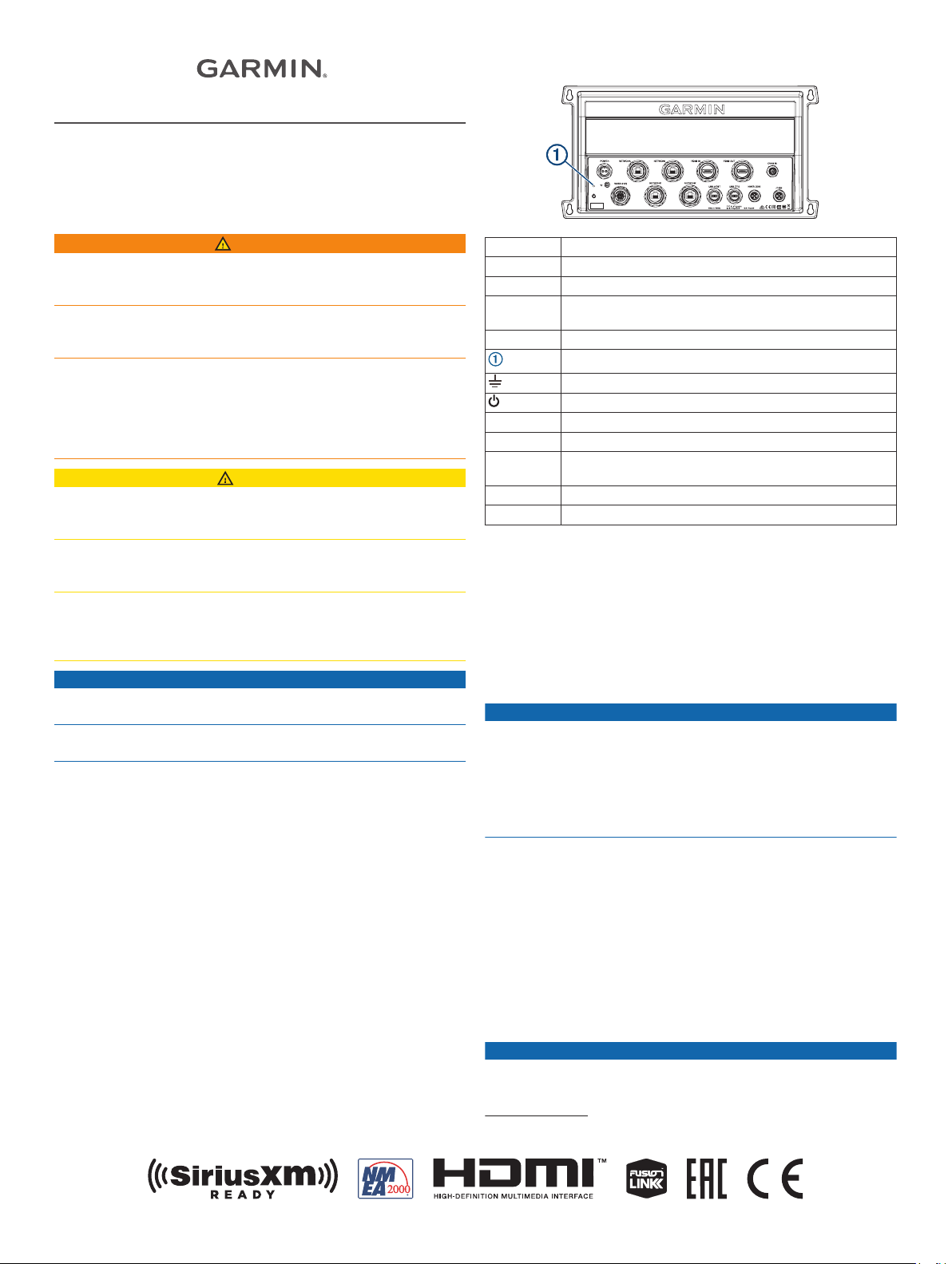
Connector View
WARNING
Failure to follow these warnings, cautions, and notices could
result in personal injury, damage to the vessel or device, or poor
product performance.
See the Important Safety and Product Information guide in the
product box for product warnings and other important
information.
When connecting the power cable, do not remove the in-line
fuse holder. To prevent the possibility of injury or product
damage caused by fire or overheating, the appropriate fuse
must be in place as indicated in the product specifications. In
addition, connecting the power cable without the appropriate
fuse in place voids the product warranty.
CAUTION
To avoid possible personal injury, always wear safety goggles,
ear protection, and a dust mask when drilling, cutting, or
sanding.
To avoid possible personal injury or damage to the device and
vessel, disconnect the vessel's power supply before beginning
to install the device.
To avoid possible personal injury or damage to the device or
vessel, before applying power to the device, make sure that it
has been properly grounded, following the instructions in the
guide.
NOTICE
For the best possible performance, the device must be installed
according to these instructions.
When drilling or cutting, always check what is on the opposite
side of the surface to avoid damaging the vessel.
Read all installation instructions before proceeding with the
installation. If you experience difficulty during the installation,
contact Garmin® Product Support.
Contacting Garmin Support
• Go to support.garmin.com for help and information, such as
product manuals, frequently asked questions, videos, and
customer support.
• In the USA, call 913-397-8200 or 1-800-800-1020.
• In the UK, call 0808 238 0000.
• In Europe, call +44 (0) 870 850 1241.
Software Update
You may need to update the chartplotter software after
installation. For the instructions on how to update the software,
see the owner's manual at garmin.com/manuals/GPSMAP8700.
POWER Power cable connection
NETWORK Garmin Marine Network
HDMI IN HDMI® in
HDMI OUT HDMI out to connect the chartplotter to a monitor.
Required for device functionality.
CVBS IN Composite video in
Status LED
Power ground
Power button
NMEA 0183 NMEA® 0183 and audio out
USB HOST Micro-USB output for connecting a touchscreen monitor
USB OTG Micro-USB input from compatible Garmin card reader1,
computer, or other supported USB accessory
NMEA 2000 NMEA 2000® network
J1939 J1939 network
Tools Needed
• Drill
• Drill bits appropriate for the surface and hardware (3.2 mm
(1/8 in.) drill bit for included screws)
• Phillips screwdriver
• Pencil
Mounting Considerations
NOTICE
This device should be mounted in a location that is not exposed
to extreme temperatures or conditions. The temperature range
for this device is listed in the product specifications. Extended
exposure to temperatures exceeding the specified temperature
range, in storage or operating conditions, may cause device
failure. Extreme-temperature-induced damage and related
consequences are not covered by the warranty.
• You must mount the device in a location where it will not be
submerged.
• You must mount the device in a location with adequate
ventilation where it will not be exposed to extreme
temperatures.
• You must mount the device at least 2.54 cm (1 in.) from
cables and other potential sources of interference.
• You must mount the device in a location that allows room for
the routing and connection of all cables.
Mounting the GPSMAP 8700 Black Box Device
NOTICE
If you are mounting the device in fiberglass, when drilling the
pilot holes, use a countersink bit to drill a clearance counterbore
1
Only compatible Garmin card readers recommended. Third-party card readers
are not guaranteed to be fully compatible.
GUID-0E7D71DD-265C-4A81-9C9D-474AAB4BB516 v2November 2020
through only the top gel-coat layer. This will help to avoid
cracking in the gel-coat layer when the screws are tightened.
NOTE: Screws are included with the device, but they may not
be suitable for the mounting surface.
Before you mount the device, you must select a mounting
location, and determine what screws and other mounting
hardware are needed for the surface.
Place the black box device in the mounting location, and
1
mark the location of the pilot holes.
Drill a pilot hole for one corner of the device.
2
Loosely fasten the device to the mounting surface with one
3
corner, and examine the other three pilot-hole marks.
Mark new pilot-hole locations if necessary, and remove the
4
device from the mounting surface.
Drill the remaining pilot holes.
5
Secure the device to the mounting location.
6
Connection Considerations
When connecting this device to power and to other Garmin
devices, you should observe these considerations.
• The power and ground connections to the battery must be
checked to make sure they are secured and cannot become
loose.
• The cables may be packaged without the locking rings
installed. The cables should be routed before the locking
rings are installed.
• After installing a locking ring on a cable, you should make
sure the ring is securely connected and the o-ring is in place
so the power or data connection remains secure.
Connecting to Power
WARNING
When connecting the power cable, do not remove the in-line
fuse holder. To prevent the possibility of injury or product
damage caused by fire or overheating, the appropriate fuse
must be in place as indicated in the product specifications. In
addition, connecting the power cable without the appropriate
fuse in place voids the product warranty.
You should connect the red wire to the same battery through the
ignition or another manual switch to turn the device on and off.
Route the power cable between the power source and the
1
device.
Connect the red power wire to the ignition or another manual
2
switch, and connect the switch to the positive (+) battery
terminal if necessary.
Connect the black wire to the negative (-) battery terminal or
3
to ground.
Connect the power cable to the device, and turn the locking
4
ring clockwise to tighten it.
Additional Grounding Consideration
This device should not need additional chassis grounding in
most installation situations. If you experience interference, you
can use the grounding screw on the housing to connect the
device to the water ground of the boat to help avoid the
interference.
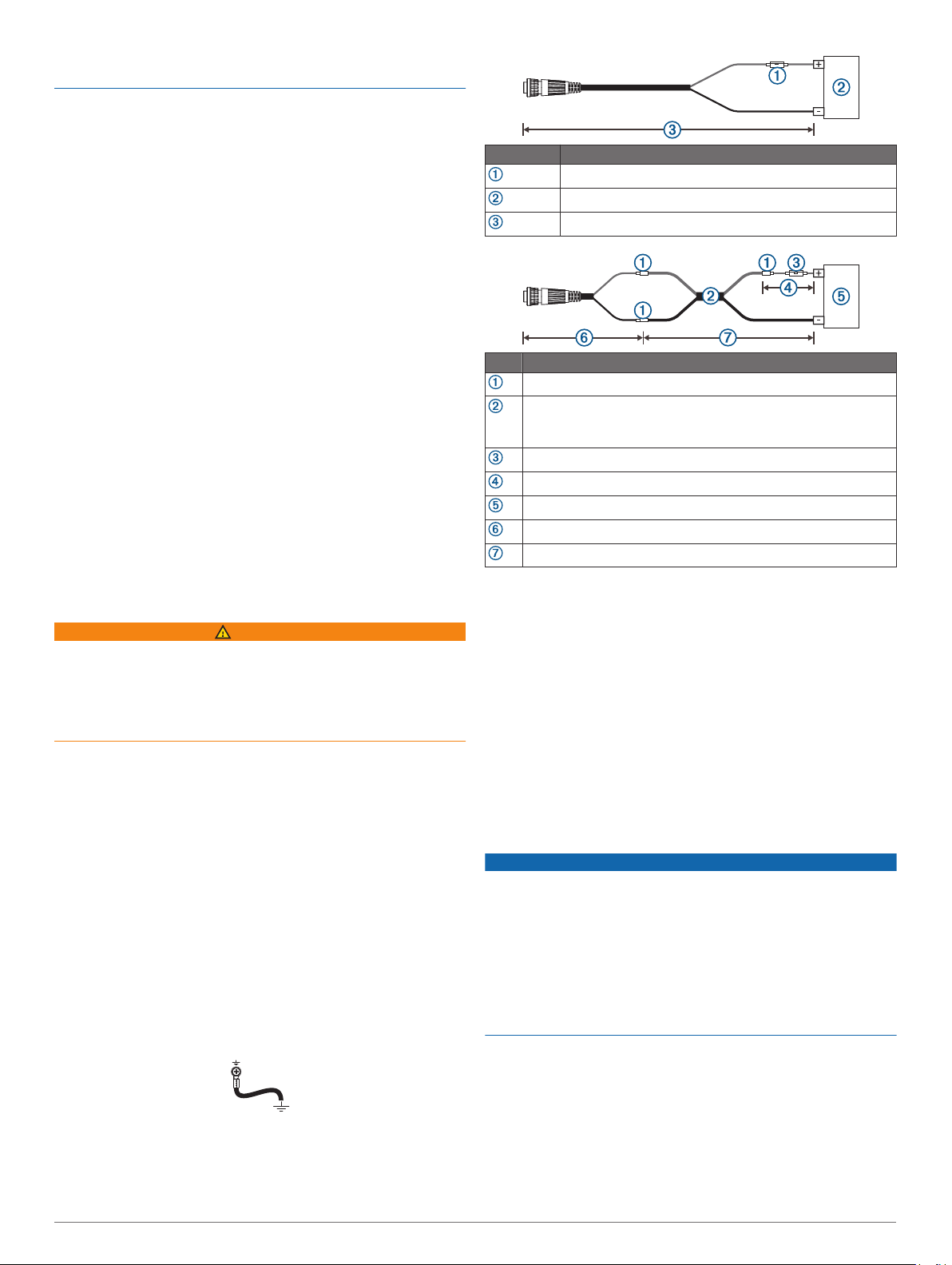
Power Cable Extensions
If necessary, the power cable can be extended using the
appropriate wire gauge for the length of the extension.
Item Description
Fuse
Battery
6 ft. (1.8 m) no extension
Item Description
Splice
• 10 AWG (5.26 mm²) extension wire, up to 15 ft. (4.6 m)
• 8 AWG (8.36 mm²) extension wire, up to 23 ft. (7 m)
• 6 AWG (13.29 mm²) extension wire, up to 36 ft. (11 m)
Fuse
8 in. (20.3 cm)
Battery
8 in. (20.3 cm)
36 ft. (11 m) maximum extension
Power Considerations
While you can turn the device on and off using the power key,
the device will likely not be easily accessible to do so. You
should consider connecting a switch or one of the following to
turn the GPSMAP 8700 device on and off:
• A GRID™ device
NOTE: A GRID 20 device will not turn the GPSMAP 8700
device on or off. Using the power key on the GRID 20 device
will place the GPSMAP 8700 device into sleep mode.
• Another Garmin chartplotter
• A GMM™ monitor
When power is applied to the GPSMAP 8700 device, the device
will turn on. You cannot disable the auto power on feature.
Garmin Marine Network Considerations
NOTICE
A Garmin Marine Network PoE Isolation Coupler
(010-10580-10) must be used when connecting any third-party
device, such as a FLIR® camera, to a Garmin Marine Network.
Connecting a Power over Ethernet (PoE) device directly to a
Garmin Marine Network chartplotter damages the Garmin
chartplotter and may damage the PoE device. Connecting any
third-party device directly to a Garmin Marine Network
chartplotter will cause abnormal behavior on the Garmin
devices, including the devices not properly turning off or the
software becoming inoperable.
This device can connect to additional Garmin Marine Network
devices to share data such as radar, sonar, and detailed
mapping. When connecting Garmin Marine Network devices to
this device, observe these considerations.
• All devices connected to the Garmin Marine Network must be
connected to the same ground. If multiple power sources are
used for Garmin Marine Network devices, you must tie all
ground connections from all power supplies together using a
low resistance connection or tie them to a common ground
bus bar, if available.
2
• A Garmin Marine Network cable must be used for all Garmin
Marine Network connections.
◦ Third-party CAT5 cable and RJ45 connectors must not be
used for Garmin Marine Network connections.
◦ Additional Garmin Marine Network cables and connectors
are available from your Garmin dealer.
• The NETWORK ports on the device each act as a network
switch. Any compatible device can be connected to any
NETWORK port to share data with all devices on the boat
connected by a Garmin Marine Network cable.
Station Connection Considerations
This device can be set up in conjunction with other compatible
Garmin devices to work together as a station. When planning
stations on your boat, observe these considerations.
• Devices earlier than the GPSMAP 8000 series and GPSMAP
8500 series cannot be used in a station.
• Although it is not necessary, it is recommended that you
install all of the devices you plan to use in one station near
each other.
• No special connections are necessary to create a station, as
long as all of the devices are connected to the Garmin Marine
Network (Garmin Marine Network Considerations, page 2).
• Stations are created and modified using the device software.
See the owner's manual provided with the device for more
information.
GMM Monitor Connection Considerations
You can use a GMM monitor to view and control the GPSMAP
8700. When connecting a GMM monitor to the GPSMAP 8700
device, you must observe these considerations.
• The touchscreen functionality of the GMM monitor can be
used to control one GPSMAP 8700 device.
• Although it is recommended to use Garmin DVI-D cables,
high-quality third-party DVI-D cables may be used. Before
you route a DVI-D cable, you should connect all devices to it
for testing.
• You must use an HDMI to DVI-D cable or adapter.
• You must connect the GMM monitor to the same power
source as the GPSMAP 8700 device. If this is not possible,
you must connect the devices to the same ground.
• You must connect the GMM monitor to a NETWORK port on
the GPSMAP 8700 device or to the same Garmin Marine
Network as the GPSMAP 8700 device.
• The touch data is sent over the Garmin Marine Network.
Devices
Item Device
GPSMAP chartplotter
GMM touchscreen monitor
NMEA 2000 Considerations
NOTICE
If you are connecting to an existing NMEA 2000 network,
identify the NMEA 2000 power cable. Only one NMEA 2000
power cable is required for the NMEA 2000 network to operate
properly.
A NMEA 2000 Power Isolator (010-11580-00) should be used in
installations where the existing NMEA 2000 network
manufacturer is unknown.
If you are installing a NMEA 2000 power cable, you must
connect it to the boat ignition switch or through another in-line
switch. NMEA 2000 devices will drain your battery if the NMEA
2000 power cable is connected to the battery directly.
This device can connect to a NMEA 2000 network on your boat
to share data from NMEA 2000 compatible devices such as a
GPS antenna or a VHF radio. The included NMEA 2000 cables
and connectors allow you to connect the device to your existing
NMEA 2000 network. If you do not have an existing NMEA 2000
network you can create a basic one using cables from Garmin.
If you are unfamiliar with NMEA 2000, you should read the
Technical Reference for NMEA 2000 Products at garmin.com
/manuals/nmea_2000.
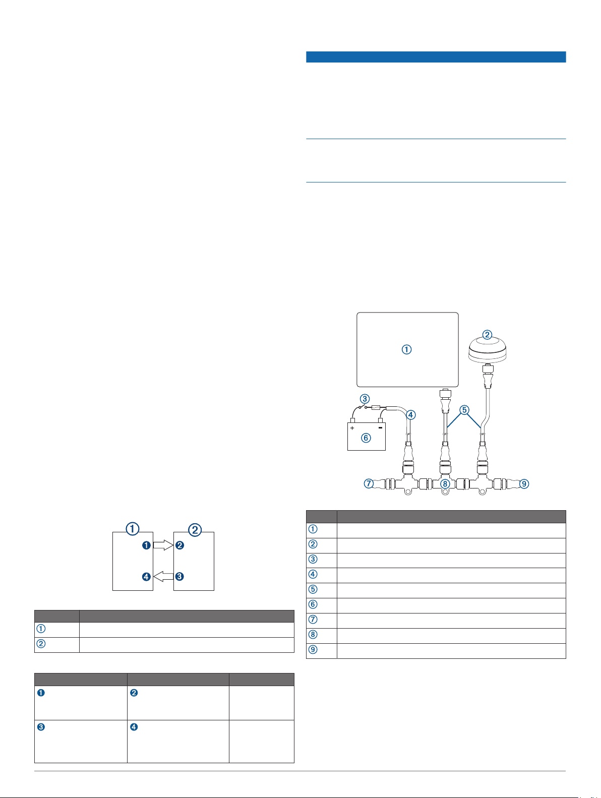
The port labeled NMEA 2000 is used to connect the device to a
standard NMEA 2000 network.
Item Description
NMEA 2000 compatible Garmin device
GPS antenna
Ignition or in-line switch
NMEA 2000 power cable
NMEA 2000 drop cable
12 Vdc power source
NMEA 2000 terminator or backbone cable
NMEA 2000 T-connector
NMEA 2000 terminator or backbone cable
Connections
From To Cable
DVI-D cable with
Chartplotter's HDMI
OUT port
GMM monitor's
GARMIN PROCESSOR
BOX port
GMM monitor's MAIN DVI
VIDEO IN port
Chartplotter's NETWORK
port or the Garmin Marine
Network
an HDMI
adapter
Garmin Marine
Network Cable
NMEA 0183 Connection Considerations
• The chartplotter provides one Tx (transmit) port and one Rx
(receive) port.
• Each port has 2 wires, labeled A and B according to the
NMEA 0183 convention. The corresponding A and B wires of
each internal port should be connected to the A (+) and B (-)
wires of the NMEA 0183 device.
3
 Loading...