

Garmin GPSMAP 8400 Series, GPSMAP 8600 Series Installation Instructions Manual
GPSMAP® 8400/8600 SERIES
INSTALLATION
INSTRUCTIONS
Important Safety Information
WARNING
See the Important Safety and Product Information guide in the
product box for product warnings and other important
information.
When connecting the power cable, do not remove the in-line
fuse holder. To prevent the possibility of injury or product
damage caused by fire or overheating, the appropriate fuse
must be in place as indicated in the product specifications. In
addition, connecting the power cable without the appropriate
fuse in place voids the product warranty.
CAUTION
Always wear safety goggles, ear protection, and a dust mask
when drilling, cutting, or sanding.
NOTICE
When drilling or cutting, always check what is on the opposite
side of the surface.
To obtain the best performance and to avoid damage to your
boat, install the device according to these instructions.
Read all installation instructions before proceeding with the
installation. If you experience difficulty during the installation,
contact Garmin® Product Support.
Contacting Garmin Support
• Go to support.garmin.com for help and information, such as
product manuals, frequently asked questions, videos, and
customer support.
• In the USA, call 913-397-8200 or 1-800-800-1020.
• In the UK, call 0808 238 0000.
• In Europe, call +44 (0) 870 850 1241.
Updating the Device Software
You may need to update the device software when you install
this device or add an accessory to the network. You can use
one of two methods to update the software.
• Use the ActiveCaptain™ app.
• Download the update from www.garmin.com/support
/software/marine.html using a memory card (32 GB max.)
and a computer running Windows® operating system.
For more information, see the owner's manual at
www.garmin.com/manuals/GPSMAP84xx-86xx.
Registering Your Device
Help us better support you by completing our online registration
today. You can register your device using one of two methods.
• Use the ActiveCaptain app.
• Go to my.garmin.com/registration and sign into your Garmin
account to register the device.
Keep the original sales receipt, or a photocopy, in a safe place.
After you add devices to the chartplotter network, register the
new devices.
Tools Needed
• Drill and drill bits
◦ 3.0 mm (1/8 in.) drill bit for bail mounting
◦ 14.6 mm (9/16 in.) drill bit for flush mounting
◦ 3.2 mm (1/8 in.) drill bit for flush mounting using wood
screws
◦ 3.6 mm (9/64 in.) drill bit for flush mounting using the nut
plate
◦ 6.0 mm (1/4 in.) drill bit for flush mounting using the nut
plate
• #2 Phillips screwdriver
• Jigsaw or rotary tool
• File and sandpaper
• Marine-grade sealant, approved for use on plastics
(recommended)
Mounting Considerations
NOTICE
This device should be mounted in a location that is not exposed
to extreme temperatures or conditions. The temperature range
for this device is listed in the product specifications. Extended
exposure to temperatures exceeding the specified temperature
range, in storage or operating conditions, may cause device
failure. Extreme-temperature-induced damage and related
consequences are not covered by the warranty.
You can flush mount the device in the dashboard, or bail mount
the device on the dashboard.
When selecting a mounting location, observe these
considerations.
• You should mount the device to provide an optimal viewing
angle as you operate your boat.
• You must select a location that is strong enough to support
the weight of the device and protect it from excessive
vibration or shock.
• To avoid interference with a magnetic compass, you must not
mount the device closer to a compass than the compass-safe
distance value listed in the product specifications.
• You must select a location that allows room for the routing
and connection of all cables.
• You should select a location that allows for easy access to
the device touchscreen.
• You should select a location that allows for access to the
microSD® card in the back of the device. If the location does
not allow access, you must insert the memory cards before
installing the device.
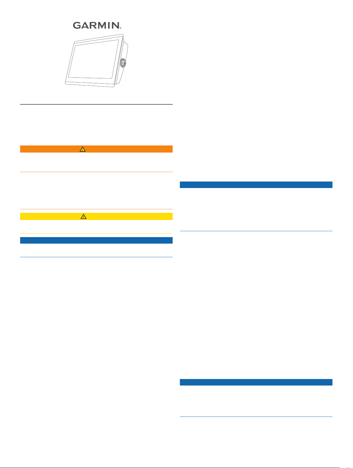
Bail Mounting the Device
NOTICE
If you are mounting the bracket on fiberglass with screws, it is
recommended to use a countersink bit to drill a clearance
counterbore through only the top gel-coat layer. This will help to
avoid cracking in the gel-coat layer when the screws are
tightened.
You can use the bracket to bail mount the device on a flat
surface. The bracket and hardware are included in some
models.
March 2019
190-02469-02_0A
Using the bail-mount bracket as a template, mark the pilot
1
holes .
Using a 3 mm (1/8 in.) drill bit, drill the pilot holes.
2
Secure the bail-mount bracket to the surface using the
3
included washers and wood screws .
Install the bail-mount knobs on the sides of the device.
4
Place the device in the bail-mount bracket, and tighten the
5
bail-mount knobs.
Install the trim caps by snapping them in place around the
6
edges of the device.
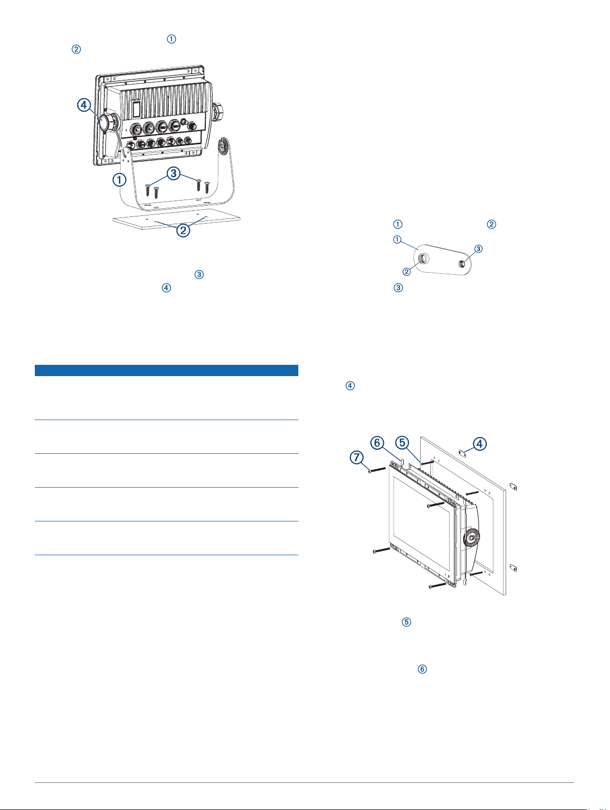
Mounting the Device
NOTICE
Be careful when cutting the hole to flush mount the device.
There is only a small amount of clearance between the case and
the mounting holes, and cutting the hole too large could
compromise the stability of the device after it is mounted.
Use only the included hardware when mounting this device.
Using mounting hardware not provided with the device may
damage the device.
To avoid potential damage to the powder coating, use only the
included screws to mount the device. Using screws other than
the ones included will void your warranty.
Do not remove the blue, rubber protective bumper until after the
installation is complete. The bumper helps protect the device
from damage during installation.
If you will not have access to be back of the device and the
microSD memory card slots after installations, you should install
the microSD memory card prior to installation.
If necessary, use a file and sandpaper to refine the size of
6
the cutout.
After the device fits correctly in the cutout, ensure the
7
mounting holes on the device line up with the larger 6 mm
(1/4 in.) holes on the template.
If the mounting holes on the device do not line up, mark the
8
new hole locations.
Based on your mounting surface, drill or punch and tap the
9
larger holes:
• Drill 3.2 mm (1/8 in.) pilot holes for the included wood
screws, and skip to step 18.
• Drill 6 mm (1/4 in.) holes for the included nut plate and
machine screws.
• Drill and tap M4 holes for the included machine screws,
and skip to step 18.
If using the nut plates, starting in one corner of the template,
10
place a nut plate over the larger hole drilled in step 9.
The smaller hole on the nut plate should line up with the
smaller 3.6 mm (9/64 in.) hole on the template.
If the smaller hole on the nut plate does not line up with the
11
smaller hole on the template, mark the new hole location.
Repeat steps 10 and 11 for each nut plate.
12
Using a 3.6 mm (9/64 in.) drill bit, drill the smaller holes.
13
Remove the template from the mounting surface.
14
Starting in one corner of the mounting location, place a nut
15
plate on the back of the mounting surface, lining up the
large and small holes.
The raised portion of the nut plate should fit into the larger
hole.
The included template and hardware can be used to flush mount
the device in your dashboard. There are three options for
hardware based on the mounting surface material.
• You can drill pilot holes and use the included wood screws.
• You can drill holes and use the included nut plates and
machine screws. The nut plates can add stability to a thinner
surface.
• You can drill holes, tap them to M4, and use the included
machine screws.
Trim the template and make sure it fits in the location where
1
you want to mount the device.
Secure the template to the selected location.
2
Using an 14.6 mm (9/16 in.) drill bit, drill one or more of the
3
holes inside the corners of the solid line on the template to
prepare the mounting surface for cutting.
Using a jigsaw or rotary tool, cut the mounting surface along
4
the inside of the solid line on the template.
Place the device in the cutout to test the fit.
5
2
Secure the nut plate to the mounting surface by fastening an
16
included M3 screw through the smaller 3.6 mm (9/64 in.)
hole.
Repeat steps 15 and 16 for each of the nut plates along the
17
top and bottom of the device.
Install the foam gasket on the back of the device.
18
The pieces of the foam gasket have adhesive on the back.
Make sure you remove the protective liner before installing
them on the device.
If you will not have access to the back of the device after you
19
mount it, connect all necessary cables and install microSD
cards in the back of the device before placing it into the
cutout.
NOTE: To prevent corrosion of the metal contacts, cover
unused connectors with the attached weather caps.
Apply marine sealant between the mounting surface and the
20
device to properly seal and prevent leakage behind the
dashboard.
If you will have access to the back of the device, apply
21
marine sealant around the cutout.
Place the device into the cutout.
22
Secure the device to the mounting surface using the included
23
M4 screws or wood screws, depending on the mounting
method.
Carefully remove and discard the rubber protective bumper.
24
Wipe away all excess marine sealant.
25
Install the trim caps by snapping them in place around the
26
edges of the device.
Connection Considerations
When connecting this device to power and to other Garmin
devices, you should observe these considerations.
• The power and ground connections to the battery must be
checked to make sure they are secured and cannot become
loose.
• The cables may be packaged without the locking rings
installed. The cables should be routed before the locking
rings are installed.
• After installing a locking ring on a cable, you should make
sure the ring is securely connected and the o-ring is in place
so the power or data connection remains secure.
Connecting to Power
WARNING
When connecting the power cable, do not remove the in-line
fuse holder. To prevent the possibility of injury or product
damage caused by fire or overheating, the appropriate fuse
must be in place as indicated in the product specifications. In
addition, connecting the power cable without the appropriate
fuse in place voids the product warranty.
Route the power cable to the power source and to the device.
1
Connect the red wire to the positive (+) battery terminal, and
2
connect the black wire to the negative (-) battery terminal.
Connect the power cable to the device, and turn the locking
3
ring clockwise to tighten it.
Additional Grounding Consideration
This device should not need additional chassis grounding in
most installation situations. If you experience interference, you
can use the grounding screw on the housing to connect the
device to the water ground of the boat to help avoid the
interference.
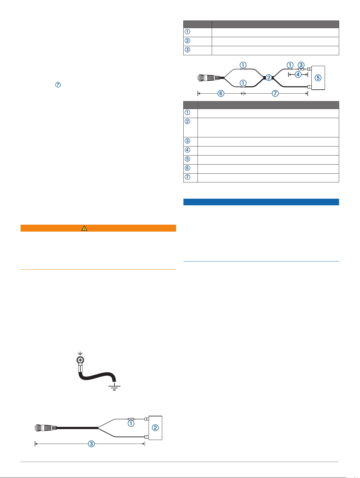
Power Cable Extensions
If necessary, the power cable can be extended using the
appropriate wire gauge for the length of the extension.
Item Description
Fuse
Battery
6 ft. (1.8 m) no extension
Item Description
Splice
• 10 AWG (5.26 mm²) extension wire, up to 15 ft. (4.6 m)
• 8 AWG (8.36 mm²) extension wire, up to 23 ft. (7 m)
• 6 AWG (13.29 mm²) extension wire, up to 36 ft. (11 m)
Fuse
8 in. (20.3 cm)
Battery
8 in. (20.3 cm)
36 ft. (11 m) maximum extension
Garmin Marine Network Considerations
NOTICE
A Garmin Power over Ethernet (PoE) Isolation Coupler (P/N
010-10580-10) must be used when connecting any third-party
device, such as a FLIR® camera, to a Garmin Marine Network.
Connecting a PoE device directly to a Garmin Marine Network
chartplotter damages the Garmin chartplotter and may damage
the PoE device. Connecting any third-party device directly to a
Garmin Marine Network chartplotter will cause abnormal
behavior on the Garmin devices, including the devices not
properly turning off or the software becoming inoperable.
This device can connect to additional Garmin Marine Network
devices to share data such as radar, sonar, and detailed
mapping. When connecting Garmin Marine Network devices to
this device, observe these considerations.
• All devices connected to the Garmin Marine Network must be
connected to the same ground.
• A Garmin Marine Network cable must be used for all Garmin
Marine Network connections.
◦ Third-party CAT5 cable and RJ45 connectors must not be
used for Garmin Marine Network connections.
◦ Additional Garmin Marine Network cables and connectors
are available from your Garmin dealer.
• The NETWORK ports on the device each act as a network
switch. Any compatible device can be connected to any
NETWORK port to share data with all devices on the boat
connected by a Garmin Marine Network cable.
Station Connection Considerations
This device can be set up in conjunction with other compatible
Garmin devices to work together as a station. When planning
stations on your boat, observe these considerations.
• Devices earlier than the GPSMAP 8000 series and GPSMAP
8500 series cannot be used in a station.
• Although it is not necessary, it is recommended that you
install all of the devices you plan to use in one station near
each other.
• No special connections are necessary to create a station, as
long as all of the devices are connected to the Garmin Marine
Network (Garmin Marine Network Considerations, page 3).
3
 Loading...