

Page 1
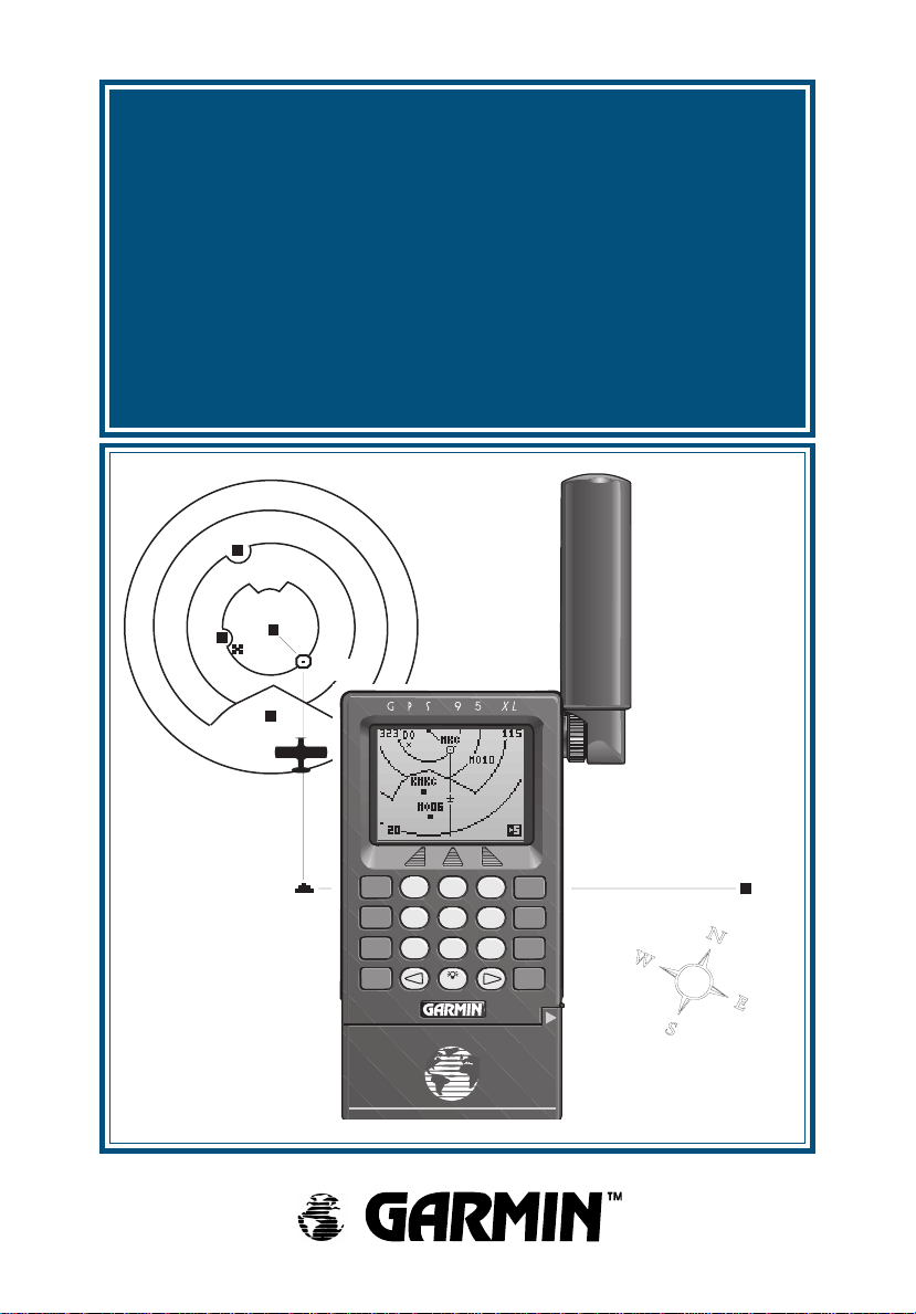
GPS 95 XL
PERSONAL NAVIGATOR
OWNER'S MANUAL
KMCI
MKC
PWR
TYGER
STAT
GO
AUTO
STO
CLR
ABC
1
JKL
TO
4
STU
7
DEF
MNO
VWX
GHI
NAV
3
2
PQR
5
8
0
WPT
6
YZ--
RTE
9
ENT
TM
KCOU
Page 2

GPS 95 XL
Personal Navigator
OWNER'S MANUAL
TM
Page 3

© 1994 GARMIN, 9875 Widmer Road, Lenexa, KS 66215, USA
Printed in Taiwan.
All rights reserved. No part of this manual may be reproduced or
transmitted in any form or by any means, electronic or mechanical,
including photocopying and recording, for any purpose without the
express written permission of GARMIN.
Information in this document is subject to change without notice.
GARMIN reserves the right to change or improve their products and to
make changes in the content without obligation to notify any person or
organization of such changes or improvements.
August, 1994 190-00080-00 Rev. A
Page 4

PREFACE
GARMIN thanks you for selecting our high performance, full featured
Personal NavigatorTM. The GPS 95 represents our continued commitment
to provide you with a portable navigation unit that is versatile, extremely
accurate, and easy to use. We are confident you will enjoy using your unit
for many years to come.
The GPS 95's rugged construction and quality components offer the reliability
demanded by the harshest operating environments. It may be used in
aircraft, marine vessels and land vehicles, as well as by hunters, hikers, and
military forces. The unit may be operated portably using its own battery pack,
or it may use a 5-40 volt DC external power source for fixed mounted
applications. You can even use a 115- or 230-volt AC adaptor for planning
trips at home.
This manual and accompanying quick reference guide provide complete
information on safely operating the GPS 95 to its full potential. Sample trips
have been planned for you to practice your navigation skills using the builtin simulator. Afterwards, try a trip of your own to realize the value of the GPS
95 as your Personal NavigatorTM. If you have any questions or comments,
our Product Support Department is eager to serve you at 1-800-800-1020 or
913-599-1515. GARMIN is fully committed to your satisfaction as a customer.
GARMIN International
9875 Widmer Road
Lenexa, KS 66215 USA
GARMIN / Europe Ltd.
Robert House, Station Approach
Romsey, Hampshire SO51 8DU UK
i
Page 5

CAUTION
The GPS system is operated by the government of the United States which
is solely responsible for its accuracy and maintenance. The system is under
development and is subject to changes which could affect the accuracy and
performance of all GPS equipment. Although the GPS 95 is a precision
electronic NAVigation AID (NAVAID), any NAVAID can be misused or
misinterpreted, and therefore become unsafe. Use the GPS 95 at your own
risk. To reduce the risk, carefully review and understand all aspects of this
Owner's Manual and thoroughly practice operation using the simulator mode
prior to actual use. When in actual use, carefully compare indications from
the GPS 95 to all available navigation sources including the information from
other NAVAIDs, visual sightings, charts, etc. For safety, always resolve any
discrepancies before continuing navigation.
NOTE
This device has been tested and found to comply with the limits for a Class
B digital device, pursuant to Part 15 of the FCC Rules. Operation is subject
to the following two conditions: (1) This device may not cause harmful
interference, and (2) this device must accept any interference received,
including interference that may cause undesired operation.
This device generates, uses and can radiate radio frequency energy and, if
not installed and used in accordance with the instructions, may cause
harmful interference to radio communications. However, there is no guarantee
that interference will not occur in a particular installation. If this device does
cause harmful interference to radio or television reception, which can be
determined by turning the device off and on, you are encouraged to try to
correct the interference by one or more of the following measures:
· Reorient or relocate the receiving antenna.
· Increase the separation between this device and the receiver.
· Connect this device to an outlet on a different circuit than that to which
the receiver is connected.
· Consult the dealer or an experience radio/TV technician for help.
This device contains no user-serviceable parts. Repairs should only be
performed by an authorized GARMIN service center. Unauthorized repairs
or modifications to this device could void your warranty and your authority to
operate this device under Part 15 regulations.
ii
Page 6

TABLE OF CONTENTS
CHAPTER PAGE
1 INTRODUCING THE GARMIN GPS 95 1-1
1.1 Capabilities 1-1
1.2 Aviation Database 1-2
1.3 Basic Package 1-3
1.4 Optional Accessories 1-5
1.5 Operational Mode 1-6
2 GETTING STARTED 2-1
2.1 Front Panel 2-1
2.2 Softkey Operation 2-1
2.3 Cursor and Fields 2-2
2.4 Keypad Operation 2-2
2.5 Entering Data 2-4
2.6 Viewing Messages 2-5
2.7 Turning the GPS 95 On 2-5
2.8 Turning the GPS 95 Off 2-7
2.9 Learning to Use the GPS 95 2-8
3 WAYPOINTS AND AIRSPACES 3-1
3.1 Waypoint Categories 3-2
3.2 Airport Information 3-3
3.3 VOR Information 3-6
3.4 NDB Information 3-7
3.5 Intersection Information 3-8
3.6 User Waypoint Information 3-9
3.7 Creating User Waypoints 3-10
3.8 Waypoint List 3-12
3.9 Using Waypoints 3-13
3.10 Using Waypoints by Scanning 3-14
3.11 Reviewing Waypoints 3-16
3.12 Nearest Waypoints 3-17
3.13 SUA Page and Messages 3-18
iii
Page 7

4 GETTING THERE FAST - GOTO 4-1
5 NAVIGATION INFORMATION 5-1
5.1 Navigation Summary Page 5-1
5.2 Map Display 5-3
5.3 Map Configuration 5-5
5.4 Present Position 5-6
5.5 Sample Trip 5-7
6 ROUTES 6-1
6.1 Route Definition 6-2
6.2 Creating and Copying Routes 6-3
6.3 Activating and Inverting Routes 6-4
6.4 Editing Routes 6-4
6.5 Deleting Routes 6-5
6.6 Active Route 6-5
6.7 Route List 6-6
7 AUTOSTORE
7.1 Creating Waypoints with AutoStore
7.2 Building Routes with AutoStore
TM
TM
TM
8 GPS STATUS AND MENU PAGES 8-1
8.1 Bar Graph Page 8-2
8.2 Satellite Status Page 8-3
8.3 Satellite Skyview Page 8-4
8.4 Menu Pages 8-4
8.5 Operating Mode/Nearest Airport Search 8-5
8.6 Units/Heading Setup 8-6
8.7 Map Datum Selection 8-7
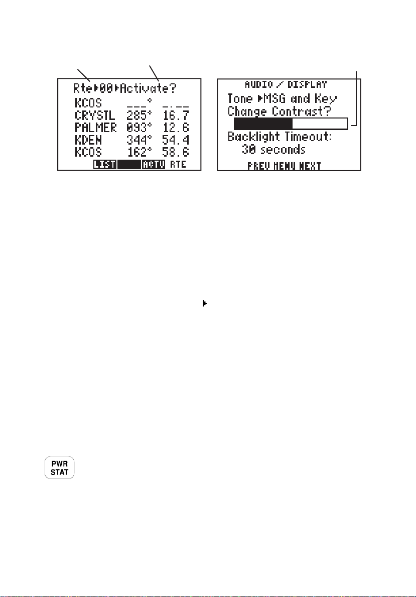
8.8 Audio and Display Setup 8-8
8.9 Track Log Setup 8-9
8.10 SUA Alarms 8-11
8.11 Arrival Alarm / CDI Setup 8-12
8.12 Input/Output Setup 8-14
8.13 Beacon Receiver Setup 8-16
8.14 Messages 8-17
iv
7-1
7-1
7-2
Page 8

8.15 Density Altitude / True Airspeed / Winds Aloft 8-17
8.16 Trip and Fuel Planning 8-18
8.17 Date/Time Settings 8-20
8.18 Sunrise/Sunset Planning 8-21
8.19 Vertical Navigation Planning 8-22
9 SAMPLE TRIP USING ROUTES 9-1
10 SUA FEATURES EXPLAINED! 10-1
10.1 Flying Toward and Entering an SUA 10-1
10.2 Flying Near an SUA's Boundary 10-3
10.3 Sectorized Airspace - Near versus Ahead 10-4
10.4 Multiple SUAs 10-5
APPENDICES
A MESSAGES A-1
B GLOSSARY AND NAVIGATION TERMS B-1
B.1 Definitions B-1
B.2 Course To Steer (CTS) B-3
C INSTALLATION AND MAINTENANCE C-1
C.1 Specifications C-1
C.2 Electrical Wiring C-3
C.3 Yoke Mount Installation C-4
C.4 Yoke Mount Operation C-8
C.5 Surface Mounting C-10
C.6 Portable Antenna Installation C-12
C.7 Battery Pack Operation C-12
C.8 Maintenance C-13
C.9 Product Support C-14
D MAP DATUMS D-1
E UTC TIME TO LOCAL TIME OFFSET E-1
F INDEX F-1
v
Page 9

CHAPTER 1
INTRODUCING THE GARMIN GPS 95
1.1 CAPABILITIES
The GPS 95 provides a host of powerful capabilities which were previously
found only in much larger systems:
· Performance: MultiTracTM receiver tracks and uses up to eight
satellites with high sensitivity, fast first fix, and continuous navigation
updates.
· Portability: Goes anywhere - air, sea or land. Built-in simulator for
trip planning or practicing navigation skills anywhere.
· Ease of Use: Graphic screens and intuitive guidance from the display
offer ease of operation.
· Convenience: Extensive database (Americas or International), covers
airports, VORs, NDBs, intersections, special-use airspaces and
controlled airspaces. Update the database at home or in your office
using your PC.
· Navigation: Stores 500 alphanumeric user waypoints; 20 reversible
routes of 30 waypoints each. GOTO function sets instantaneous
course to waypoint of your choice. AutoStoreTM function builds routes
as you go. A flashing message annunciator keeps you fully informed
of your navigation status.
· Personalized: Customize your unit by selecting distance and speed
units, Course Deviation Indicator (CDI) sensitivity, keypad and display
features, map datums, and interface options.
· Low Power Consumption: Battery Saver operation draws less than
1.5 watts; provides up to four hours of continuous operation with the
AA battery pack.
· Trip Planning: Analyze distance, time, and fuel requirements for your
trip. Compute time of sunrise/sunset at your destination. Calculate
density altitude before you take off and true airspeed as you fly.
Vertical navigation guides you to your cruising altitude and puts you in
the traffic pattern before landing.
1-1
Page 10

· Alarms: An alarm clock and timer allow the GPS 95 to watch the clock
for you. Arrival, CDI and special-use/controlled airspace alerts help
you safely navigate your aircraft.
· Interfaces: Interface with PC-based moving map programs using
NMEA 0183 output, with Differential GPS (DGPS) beacon receivers
using RTCM (SC-104 version 2.0) input, or with marine autopilots and
graphic plotters using NMEA 0180/0182/0183 outputs. An optional
PC kit is also available to download user waypoints and routes to your
PC for permanent record.
We encourage you to read this manual and experiment using the built-in
simulator. This will help you quickly master the many features of the GPS 95.
1.2 AVIATION DATABASE
The GPS 95 features a Jeppesen database providing direct access to either
Americas or International navigation information. When the GPS 95 is turned
on the display will show which database the unit contains. Information
contained in the database is as follows:
· Airports: Identifier, city/state, country, facility name, latitude, longitude,
elevation, and fuel services.
· VORs: Identifier, city/state, country, facility name, latitude, longitude,
frequency and co-located DME (or TACAN).
· NDBs: Identifier, city/state, country, facility name, latitude, longitude
and frequency.
· Intersections: Identifier, country, latitude and longitude.
· Communication Frequencies: ATIS, ground, tower, multicom and
unicom. (Multicom and unicom frequencies are grouped together
under a “unicom” designation.)
· Runways: Runway designations, length, surface, lighting (including
frequency for pilot-controlled lighting), and graphic runway configuration.
· Special-use and Controlled Airspaces: Alert, caution, danger,
MOA, restricted, training, warning and prohibited areas. Class B /CTA
and Class C / TMA airspaces.
The Americas Database covers North, Central and South America. The
1-2
Page 11

International Database covers Europe, Africa, Asia, Australia and Greenland.
(Hawaii is contained within both database versions.) Updates for the GPS
95 database, available every 28 days, may be purchased from GARMIN on
a one-time basis or by subscription service. When ordering your first update,
a cable is also required for connection to a PC-compatible computer. (Order
cable separately at time of purchase.) Database update software will
automatically transfer the latest information into your GPS 95 making the
update process quick and simple. Your local GARMIN dealer may also be
equipped to update the database for you.
1.3 BASIC PACKAGE
Your GARMIN GPS 95 basic package includes:
· GPS 95 Unit
· AA Battery Pack
· Detachable Antenna
· Remote Antenna Cable w/Suction Cup Mount
· Yoke Mount
· Surface Mount
· Carrying Case
· Self-coiling Power/Data Cable
· Cigarette Lighter Adaptor
· Permanent Installation Wire Harness
· Lanyard
· Battery Terminal Cover
· Owner's Manual
· Quick Reference Card
· Warranty Card
The basic package allows you to use your GPS 95 for both portable and fixed
operations. The unit may be operated from the AA battery pack, or from an
external power source (5-40VDC) using the cigarette lighter adapter or
permanent installation wire harness.
Handheld Operation:
For handheld operation, the GPS 95 is powered by a AA battery pack which
should be filled with four high quality alkaline batteries commonly found in
retail stores. The detachable antenna is placed directly on the right side of
the unit. The carrying case will protect your GPS 95 when the unit is not in
use.
1-3
Page 12

In order to track GPS satellites, the unit must be situated with the antenna
pointed straight up and should not be blocked by objects or people. (Signal
reception through thin fabric, such as canvas, may be adequate but degraded).
When using the GPS 95 inside the cockpit it may be desirable to use the
remote antenna cable for better satellite visibility. The detachable antenna
is removed from the GPS 95 and replaced by one end of the remote antenna
cable. The antenna is then placed on the other end of the cable and, using
the suction cup mount, is situated where the best satellite visibility is possible.
You may need to experiment to determine the best location for the antenna.
(See Appendix C for removal of the detachable antenna.)
A lanyard is provided to prevent accidental dropping of your GPS 95.
Connect the lanyard to the eyelet on the back (at the top) of the unit
Fixed Mount Operation:
A surface mount is supplied for panel mount installation. The lower half of
the surface mount is also used with the yoke mount. (See Appendix C for
instructions on yoke mount installation.) The unit may be operated using
aircraft power through the cigarette lighter adaptor or the permanent installation
wire harness. Note that there are three cable assemblies (not counting the
remote antenna cable). The self-coiling power/data cable plugs directly into
the back of the GPS 95. The other end of the self-coiling power/data cable
plugs into either the cigarette lighter adapter or the permanent installation
wire harness, according to your needs or preferences.
While using aircraft power, you may wish to leave the battery pack in the unit.
In the event of aircraft power failure, the GPS 95 will automatically switch to
battery power. If you do not desire to leave the battery pack on the unit, a
battery terminal cover is supplied to protect the battery contacts. Remove
the battery pack from the GPS 95 and slide the battery terminal cover on in
its place. (See Appendix C for removal of the battery pack.)
In addition to supplying power to the unit, the permanent installation wire
harness allows you to interface your GPS 95 with a PC-compatible computer
or an ARGUSTM unit. When connected to a PC-compatible computer, the
GPS 95 will provide navigation information for many of the of the popular
moving map programs. (See Appendix C for connection of the GPS 95 to
other devices.)
1-4
Page 13

1.4 OPTIONAL ACCESSORIES
The following optional accessories are available for your specific needs:
· Rechargeable NiCad Battery Kit
· PC Database Update Kit
· PCX5AVD Software Kit
Rechargeable NiCad Battery Kit:
A rechargeable NiCad battery kit is available for use with the GPS 95. This
kit includes a rechargeable NiCad battery, an AC adaptor and a drop-in
charger base. Using the drop-in charger base, the NiCad battery is charged
in 12-14 hours (not to exceed 24 hours). The rechargeable NiCad battery kit
allows you to use the GPS 95 portably for extended periods (up to eight hours
per charge).
PC Database Update Kit:
The PC Database Update Kit allows you to update the GPS 95's aviation
database (Americas or International) at home, or in your office, using a PCcompatible computer. The PC Database Update Kit includes the database
diskette(s) and instructions. When ordering your first update, be sure to also
order a PC interface cable (part no. 9541). This cable, which connects to
a COM port on your PC, is not part of the update kit.
PCX5AVD Software Kit:
The PCX5AVD Software Kit allows you to download route, waypoint and
track data from the GPS 95 to your PC-compatible computer. You may also
edit this data and upload it back into the GPS 95. With the software kit you
can plot data files and/or display current position in real-time on your
computer's monitor. Data files can be printed for future reference. For
planning purposes, the software kit provides animated satellite orbit displays
and allows you to print a satellite visibility chart. The software kit includes a
3.5" diskette, an instruction manual and a PC interface cable. This cable
can be used with both the PCX5AVD Software Kit and the PC Database
Update Kit.
1-5
Page 14

1.5 OPERATIONAL MODES
While using your GPS 95, you may select from one of four operational
modes: Normal or Battery Saver modes for actual navigation, Simulator
mode for practicing/trip planning, or AutoLocate™ mode to determine your
new position when travelling several hundred miles between uses. In Normal
and Battery Saver modes, typical time to first fix is less than 2.5 minutes. (If
you have used your unit within the hour, it may take as little as 15 seconds.)
In Simulator mode the GPS 95 will not acquire satellites, but will display a
position based on the last known location or any other position that you
designate.
Normal mode offers continuous navigation updates and should be selected
when the GPS 95 will be used in a high dynamics environment (i.e., frequent
speed and heading changes). The GPS 95 will typically operate over three
hours using the AA battery pack, or over five hours using the optional NiCad
battery pack.
Battery Saver mode, suitable for most applications, offers position updates
that adapt to your needs while extending battery life. The GPS 95 will
typically operate over four hours using the AA battery pack, or over eight
hours using the optional NiCad battery pack.
Simulator mode allows you to simulate the operation of the GPS 95 while
at home or in your office. The simulator mode can be selected while learning
to use your GPS 95 and is ideal for planning routes and entering waypoints.
Keep in mind that the GPS 95 is not tracking satellites in the simulator mode.
YOU SHOULD NEVER ATTEMPT TO USE THE SIMULATOR MODE FOR
ACTUAL NAVIGATION.
AutoLocate™ mode is used when the GPS 95 has been moved more than
one thousand miles from its last known position. This mode forces the
receiver to search for a new set of satellites and compute your new position.
Once a new position is obtained, the GPS 95 will automatically revert to
whichever mode you previously used, Normal or Battery Saver.
NOTE: In lieu of selecting AutoLocate mode, you may enter a more accurate
initial position directly on the Present Position Page to speed up the
acquisition process in Normal or Battery Saver modes. (Section 5.4 provides
more information on the Present Position Page.)
1-6
Page 15
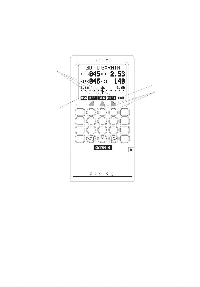
2.1 FRONT PANEL
Page Options
CHAPTER 2
GETTING STARTED
Page Annunciator
Softkeys
Message Annunciator
PWR
STAT
GO
AUTO
STO
CLR
ABC
1
JKL
4
TO
STU
7
DEF
MNO
VWX
GHI
NAV
3
2
PQR
5
8
0
WPT
6
SUA
YZ
RTE
9
ENT
The front panel consists of a 20-key keypad with a 85 x 64-pixel LCD display.
Both the display and keypad may be illuminated for nighttime operation.
2.2 SOFTKEY OPERATION
Information displayed on the LCD is referred to as a “page.” The GPS 95
works with “softkey” operation. At the bottom of the screen is a list of page
options. To select a different page, press the appropriate key (“1”, “2”, or “3”)
below the desired option. Please note that the page options must be
highlighted in order to use the softkeys. On the bottom line, extreme right,
is the page annunciator which indicates the current page you are viewing.
2-1
Page 16
2.3 CURSOR AND FIELDS
Cyclic Field
Confirmation Field
Bar Field
The area of the page which is highlighted in reverse video is called the
cursor. The cursor may be moved to locations on the page called fields
which allow you to enter data or change options. You will encounter five types
of fields.
· Numeric fields accept numbers only.
· Alphanumeric fields accept numbers as well as letters.
· Cyclic fields allow selection from several available options. A cyclic
field is preceded by a prompt ( ). You may cycle through the choices
by pushing CLR.
· Confirmation fields allow you to indicate your approval. For example,
you will be asked to confirm that you want to delete a waypoint.
Confirmation fields always end with a “?” character. Press ENT to
approve the confirmation field.
· Bar fields allow an adjustable scale entry with the length of the bar
representing the minimum to maximum setting. Use the arrow keys to
make adjustments in bar fields.
2.4 KEYPAD OPERATION
The PWR/STAT key is a dual function key that controls unit power
and system status. Pressing this when the unit is off will turn the unit
on. To turn the unit off, press and hold PWR/STAT until the display
is blank.
Pressing PWR/STAT momentarily while the unit is on will take you
to the status pages. (See Chapter 8.) If the message annunciator
is flashing and the tone sounds, you may push PWR/STAT to view
the message.
2-2
Page 17
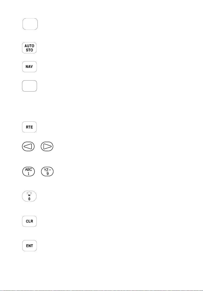
GO
Pressing GOTO allows you to instantly define a destination
waypoint and plot a course from present position to that
TO
destination. (See Chapter 4.)
Pressing AUTOSTOre allows you to capture your present
position instantaneously. (See Chapter 7.)
Pressing NAV allows you to view position and navigation
information as well as the Map Display. (See Chapter 5.)
WPT
SUA
The WPT/SUA key is a dual function key that allows you to view
information about airports, NAVAIDs, intersections and user
waypoints; or about nearby special-use/controlled airspaces.
The WPT/SUA key allows you to create, edit, delete, and
rename user waypoints. This key is also used to view nearest
waypoints. (See Chapter 3.)
The RTE key allows you to create, edit, review, activate, and
delete routes. (See Chapter 6.)
Pressing either of the arrow keys allows you to move the
cursor, scroll through information lists, and enter letters
of the alphabet.
The alphanumeric keys allow you to enter letters and
numbers. Use the arrow keys to select the desired
letter or number from a given alphanumeric key.
Pressing this key while the cursor is not on a numeric or
alphanumeric field allows you to change the backlight level.
There are two backlighting levels.
Pressing CLR erases information in the cursor field. If the
cursor is over a cyclic field, pressing CLR will toggle through
several available options.
Pressing ENT confirms an entry or selection.
2-3
Page 18

2.5 ENTERING DATA
You may enter data such as waypoint identifiers and user waypoint
coordinates on certain pages. To enter data you must first move the
cursor to the desired field by pressing the right or left arrow key. A data
entry operation is completed by pressing the ENT key. If an error is made
during the data entry process, press the CLR key to remove the erroneous
character.
To enter a number...
· Press the key that is labeled with the desired number. The numbers
will fill in from the right side of the field and move to the left as each
new number is entered. For example, if you wish to enter “51” in a
three space field, you must press the 5 and 1 keys in that order. You
do not have to enter a leading zero. (Note: When entering numbers
in an alphanumeric field press the key that is labeled with the
desired number, then press the right or left arrow key twice.)
· Press CLR if you enter an incorrect number.
· Press ENT when you have filled all significant digits of the field with
numbers.
To enter a letter...
· Press the key that is labeled with the desired letter.
· Press the right or left arrow key until the desired letter is displayed.
· Press CLR if you enter an incorrect letter.
· Press ENT when all the characters are entered.
The GPS 95 features a keypad feedback tone which will sound each time
you press a key. If you enter data which is not appropriate for the field, the
feedback tone will quickly sound three times indicating an error. The
keypad feedback tone can be turned off if you wish. (See Section 8.8.)
2-4
Page 19

2.6 VIEWING MESSAGES
From time to time, the GPS 95 will use a message to tell you of conditions
needing attention. When the GPS 95 has a new message, the MSG
annunciator will flash. When this occurs, press PWR/STAT to view the new
message(s). Press PWR/STAT again to see the page you were viewing prior
to reading the message. (See Appendix A for a complete list of GPS 95
messages.)
While the MSG annunciator is flashing, the GPS 95 will also generate a tone
to alert you of the message. (If your unit is connected to an external alarm,
it will also be activated.) Messages that demand immediate attention, such
as an arrival alarm, generate a quick tone that will not stop until you view the
message. All other messages generate a slow tone that will cease after 15
seconds. The message tone may be turned off if you wish. (See Section 8.8.)
Important messages will remain on the Message Page after being viewed.
If this occurs, the MSG annunciator will be in view but will not flash. (If no
messages exist, the MSG annunciator will not be visible.) To review these
messages, press PWR/STAT to reveal the status page options, then press
the key underneath the “MENU” page option. With the arrow keys, highlight
“Messages” and press ENT.
2.7 TURNING THE GPS 95 ON
When the GPS 95 is turned on it will automatically perform internal checks
to ensure proper operation, begin acquiring satellites and, once a sufficient
number are received, display your present position. To see this power on
sequence, take the GPS 95 outside to a location that is well away from
buildings and other structures that might limit its view of the sky.
After you turn your GPS 95 on, it will conduct a series of self tests and display
the following notice:
2-5
Page 20
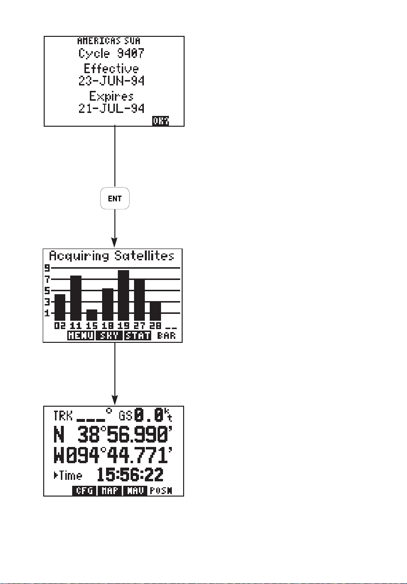
Following completion of the tests, the
Database Page will display the effective
date, cycle and expiration date of the
database. The GPS 95 will still function
with an expired database; however, you
must exercise extreme caution and
always verify that the database
information is correct before use.
(WARNING: The accuracy of the data is
assured only if current. Pilots using an
out-of-date database do so entirely at
their own risk.)
Press ENT to approve the Database
Page.
The Satellite Bar Graph Page will be
displayed, and the GPS 95 will begin
acquiring satellites.
2-6
After a position is found (and if no keys
have been pressed), the Position Page
will be displayed and the unit is ready for
normal operation. The process of
satellite acquisition is fully automatic
and, under normal circumstances, will
take approximately 2-3 minutes to obtain
navigation information. (If the unit has
been used in the past hour, it may take
as little as 15 seconds. If the GPS 95
has been moved several hundred miles
or more since it was last used, you may
want to select AutoLocate mode to
determine your new location. Refer to
Section 8.5 for more information on
selecting AutoLocate mode.)
Page 21
When four or more satellites with good geometry are available, the GPS 95
will automatically operate in the 3D mode in which latitude, longitude and
altitude are computed. If only three satellites are available, the unit will
operate in 2D mode in which only latitude and longitude are computed. When
operating in the 2D mode, the unit will use the last computed altitude or your
last entered altitude. (Section 5.4 describes how you may enter the altitude.)
Your GPS 95 will automatically update satellite orbital data as it operates. If
you have not operated your unit for a period of six months or longer, it will take
approximately 15 minutes to search the sky and collect new orbital data. You
will be informed when your unit is searching the sky with the message
“Searching the Sky.” Once satellite orbital data is collected, it will be stored
in memory. The memory is maintained by an internal battery, therefore the
data will not be lost when you turn your GPS 95 off or remove the battery
pack.
If the GPS 95 cannot acquire enough satellites for 2D or 3D navigation, you
will be informed with the message “Poor GPS coverage”. If this situation
occurs, make sure the antenna is properly connected and not obstructed by
nearby buildings or other structures.
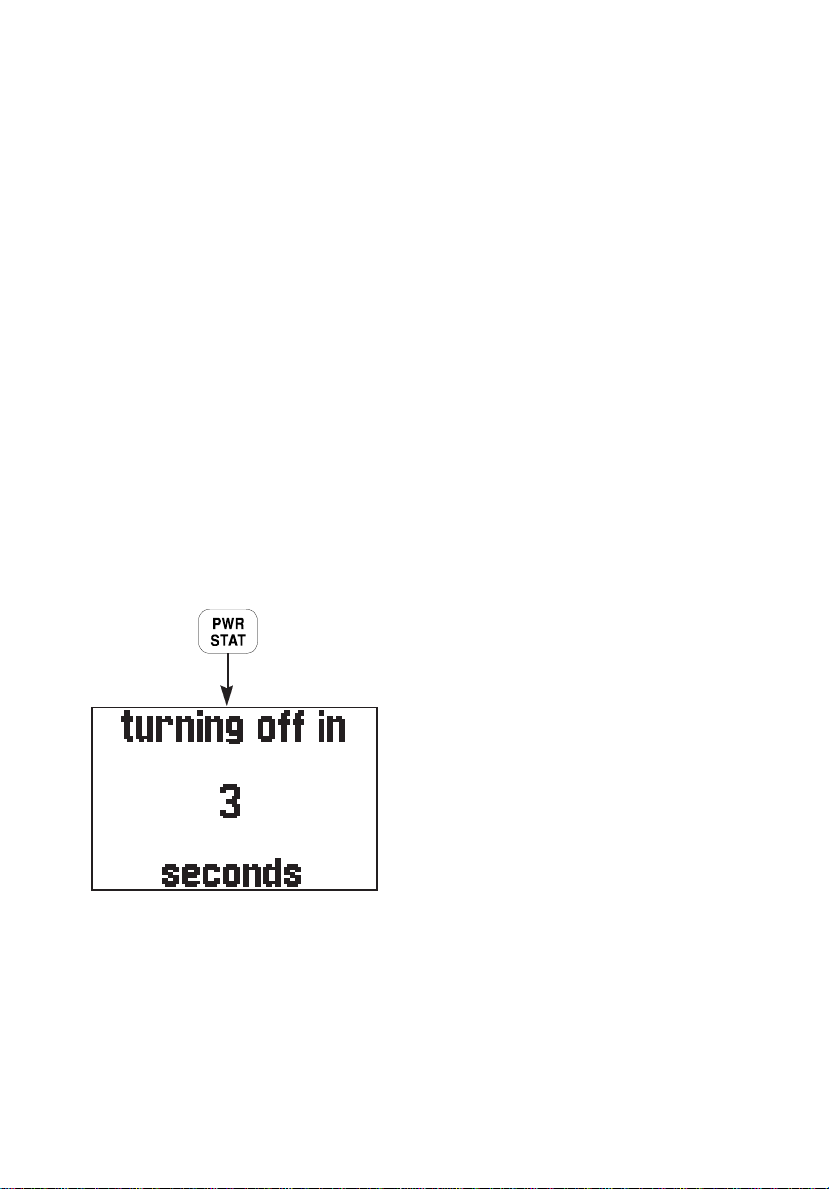
2.8 TURNING THE GPS 95 OFF
To turn the GPS 95 off, press and hold
the PWR/STAT key.
The Off Page will be displayed, the GPS
95 will perform a countdown and, after a
brief delay, will shut off. All user
waypoints, routes, and setup information
that you have entered will be maintained
while the unit is off – even if the battery
pack is removed.
2-7
Page 22

2.9 LEARNING TO USE THE GPS 95
If you are using the GPS 95 for the first time, you are encouraged to read
Chapter 3 which introduces the GPS 95's waypoint, airspace and database
features, Chapter 4 on the use of the GOTO key, and Chapter 5 for navigating
to a waypoint. A sample trip is included in Chapter 5 to get you started on
the use of the GOTO key and the various navigation pages available on your
GPS 95. You may also want to read Chapter 8 on custom setups to configure
the GPS 95 to your preferences. Afterward, you may want to read through
the rest of this manual and make further use of the built-in simulator to
practice with the advanced features.
2-8
Page 23
CHAPTER 3
WAYPOINTS AND AIRSPACES
The GPS 95 features a Jeppesen database providing Americas or International
navigation information. (Refer to Section 1.2 for a specific description of
information provided in the database.) The database contains information
about waypoints and airspaces. A basic waypoint consists of an identifier (up
to six letters and/or numbers) and its location. You can navigate to
waypoints, you can perform trip/fuel planning using waypoints, and you can
even calculate the time of sunrise and sunset for a waypoint of interest.
Airspace boundaries are provided for special-use and controlled airspaces.
Messages are provided to alert you of these nearby airspaces.
The GPS 95 features four primary waypoint and airspace pages. You may
select the desired page by pressing WPT/SUA and, if needed, the appropriate
softkey.
WPT
SUA
Nearest Waypoint Page
SUA Page
Waypoint Definition Page
Waypoint List Page
3-1
Page 24
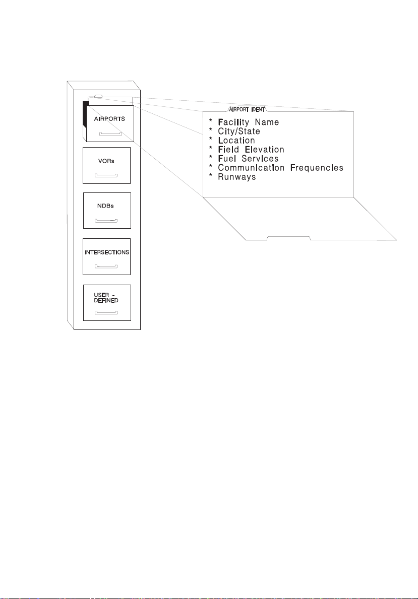
3.1 WAYPOINT CATEGORIES
Airport Ident
The GPS 95 organizes waypoints into one of five different categories:
airports, VORs, NDBs, intersections and user waypoints. This organization
is much like that of a file cabinet in which each drawer represents a different
type of information. For example, the airport drawer contains information on
airport locations, communication frequencies, runways, etc. In order to view
the information stored in a given drawer, the drawer must be opened or
selected. When using waypoints on the GPS 95 the “drawer”, or category,
is selected on a cyclic field. The following sections describe procedures used
to view information for each category of waypoint.
3-2
Page 25
3.2 AIRPORT INFORMATION
The GPS 95 features extensive information on airports:
· Identifier, facility name, city and state
· Position and elevation
· Fuel Services
· Communication frequencies
· Runway information with graphic configuration
The airport information pages may be displayed from the Waypoint Definition
Page. You may select the desired airport by its identifier, facility name or city/
state. (Refer to Section 3.10 for more information on selecting airports by
facility name or city/state.)
To view airport information...
· Press WPT/SUA and, if needed, the WPT softkey to display the
Waypoint Definition Page.
· Notice the cyclic field in the upper left corner of the page. This field will
indicate the category of waypoint that will be displayed. If “APT”, for
airport, is not currently displayed: press the right arrow key, then press
CLR (repeatedly) until “APT” is shown. (HINT: You may also select
the waypoint category by pressing the corresponding alphanumeric
key. In this case the “A” key, for airport.)
3-3
Page 26
· Press the right arrow key to move the cursor to the right of “APT”.
· Enter the identifier of the desired airport using the alphanumeric and
arrow keys. Press ENT. (Note: The airport identifiers in the GPS 95
database follow the standards set by the International Civil Aviation
Organization [ICAO].)
· With “APT” selected, a second cyclic field will appear that allows you
to view location (Locn), communication (Comm), or runway (Rnwy)
information. Highlight this second field by pressing the right arrow key
and press CLR to select the desired information page.
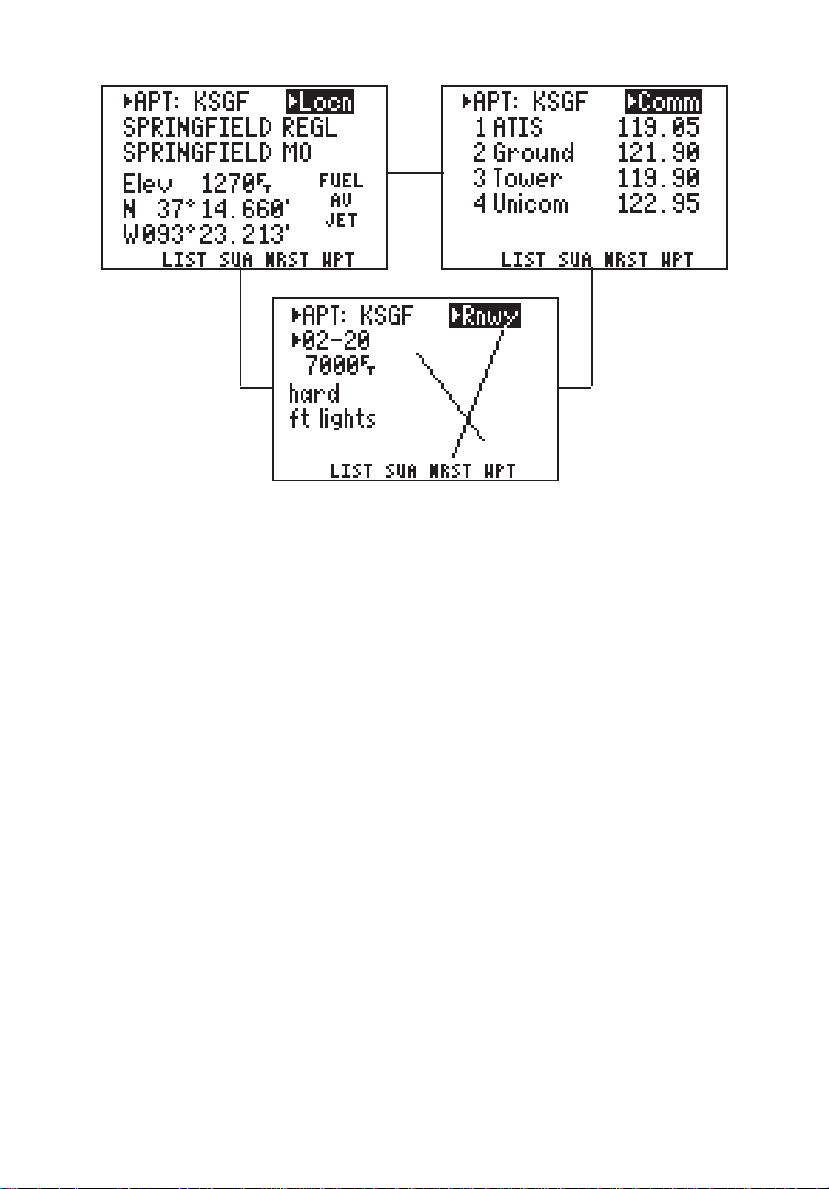
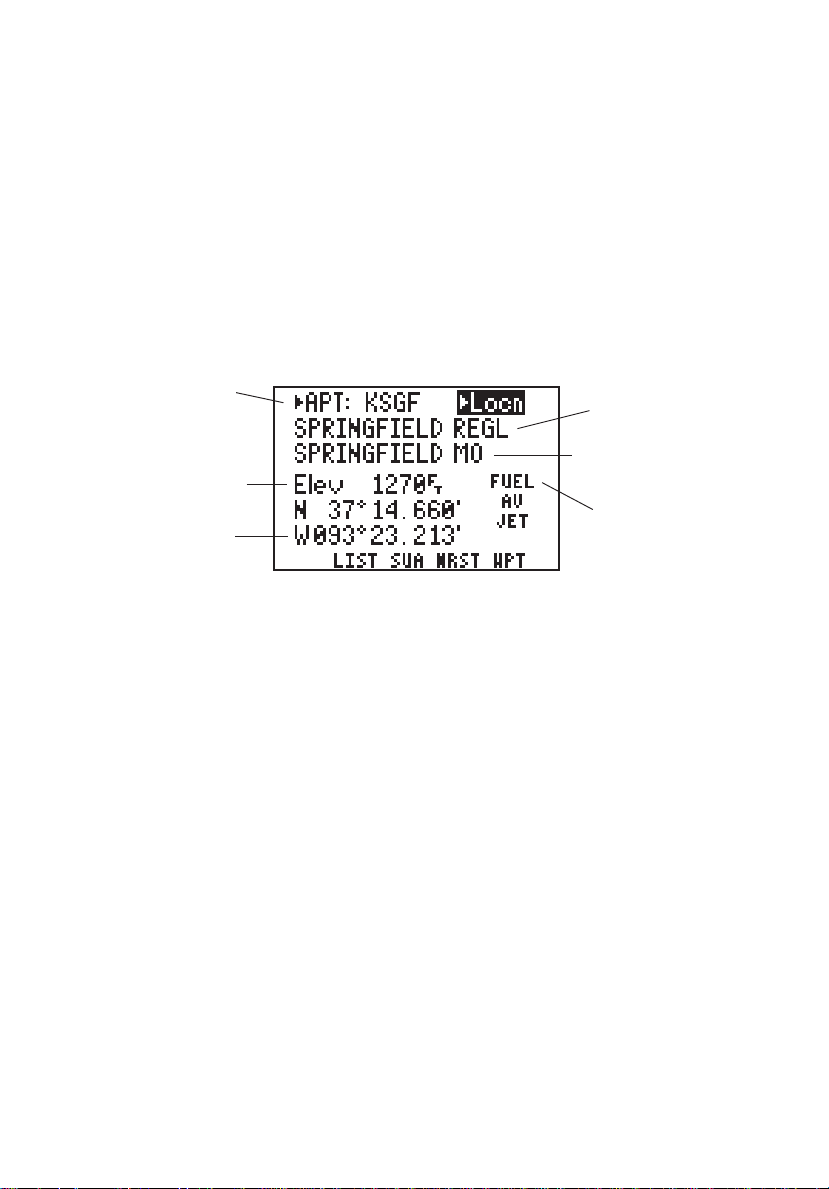
Airport Location Information
1
4
5
The airport location information includes the following
1) Airport identifier (selectable)
2) Airport facility name
3) City/state
4) Elevation (feet or meters)
5) Location
latitude/longitude -decimal degrees, degrees/decimal
minutes, degrees/minutes/decimal
seconds
grid systems -UTM/UPS, British grid, Irish grid
6) Fuel services available
2
3
6
3-4
· mo - Mogas
· av - 80/87 octane, 100LL, 100/130 octane
· jet - Jet A, Jet A-1 or Jet A+
Page 27
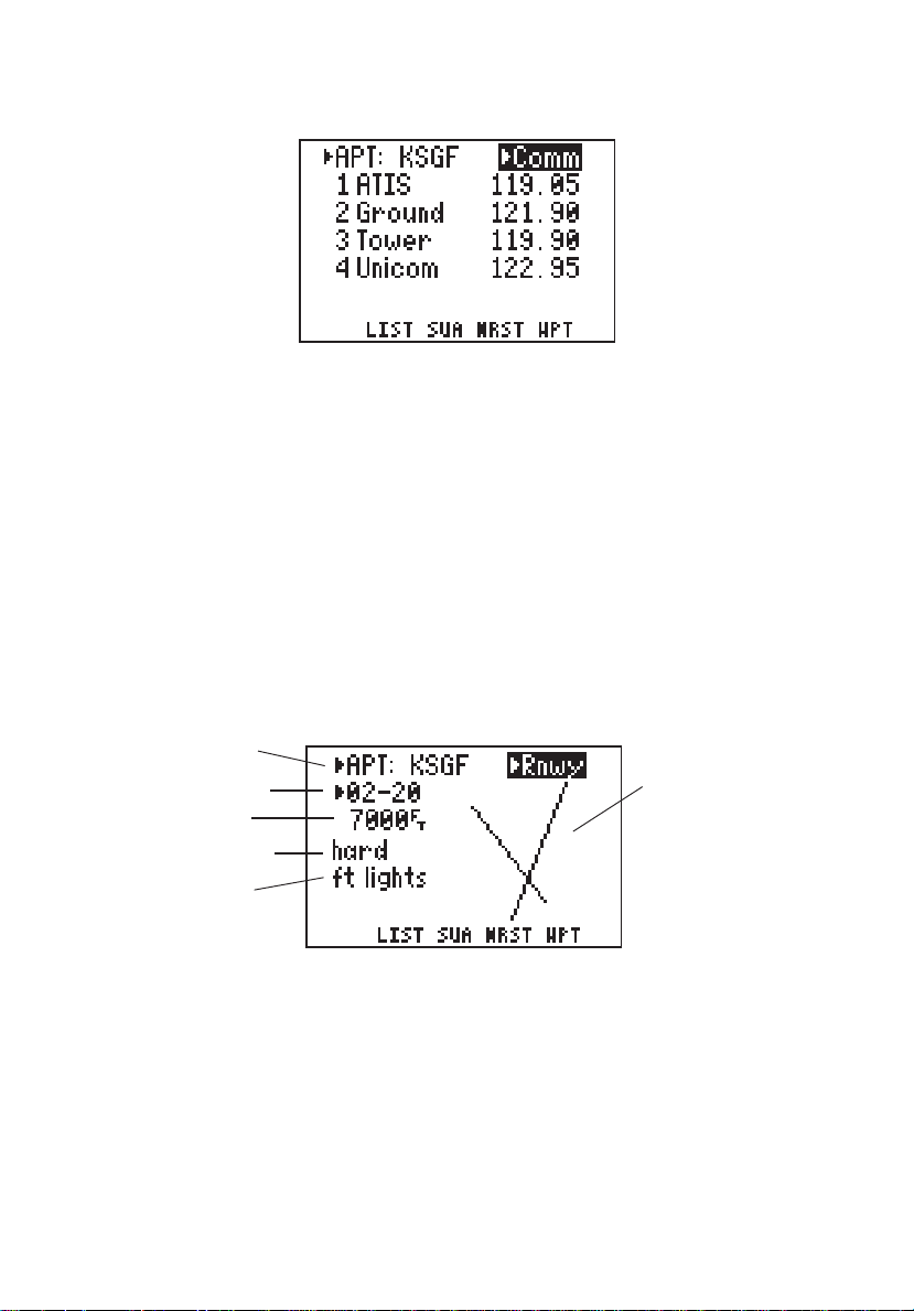
Airport Communication Information
The airport communication information includes identifier (selectable), ATIS,
ground, tower and unicom (or multicom) frequencies for the selected airport.
Up to five communication frequencies may be displayed at a time. Additional
frequencies may be viewed by scrolling.
To scroll through available frequencies...
· With the frequency information displayed, press the right arrow key
repeatedly to view additional frequencies.
· To return to the beginning of the list, press the left arrow key repeatedly
until the first frequency is displayed.
Airport Runway Information
1
2
3
4
5
The airport runway information includes the following:
1) Airport Identifier (selectable)
2) Runway designation (cyclic field)
3) Runway length (feet or meters)
6
3-5
Page 28

4) Runway surface
· hard - Hard (asphalt, concrete, etc.)
· turf - Turf (grass)
· sealed - Sealed surface
· gravel - Gravel surface
· dirt - Dirt surface
· soft - Unknown soft surface
· unkwn - Unknown surface
· water - Water landing site
5) Lighting
· no lights - No runway lighting is available
· pc lights - Pilot controlled lighting with frequency
· pt lights - Part time lighting
· ft lights - full time lighting
· unknown - Availability/type of lighting unknown
6) Graphic runway configuration, if available
The graphic runway configuration will display the layout of available
runways. For the selected airport, information for each runway is
available from the cyclic field for runway designation.
To view additional runway information...
· Using the arrow keys, place the cursor over the runway designation
field.
· Press CLR to cycle through the available runways.
3.3 VOR INFORMATION
2
1
3
4
5
6
3-6
Page 29
The GPS 95 also features considerable information on VORs:
1) Identifier (selectable)
2) Facility name
3) City/state
4) Frequency
5) DME indication, if applicable, for co-located DME or TACAN
6) Location (latitude/longitude or grid system)
You may select the desired VOR by its two-to-three-character identifier,
facility name or city/state. (See Section 3.10 for information on selecting
VORs by facility name or city/state.)
To select a VOR by identifier...
· Press WPT/SUA and, if needed, the WPT softkey to display the
Waypoint Definition Page.
· If “VOR” is not currently displayed in the upper left corner: press the
right arrow key to place the cursor on the cyclic field, then press CLR
(repeatedly) until “VOR” is shown.
· Press the right arrow key to move the cursor to the right of “VOR”.
· Enter the identifier of the desired VOR using the alphanumeric and
arrow keys. Press ENT. The information for the selected VOR is
displayed.
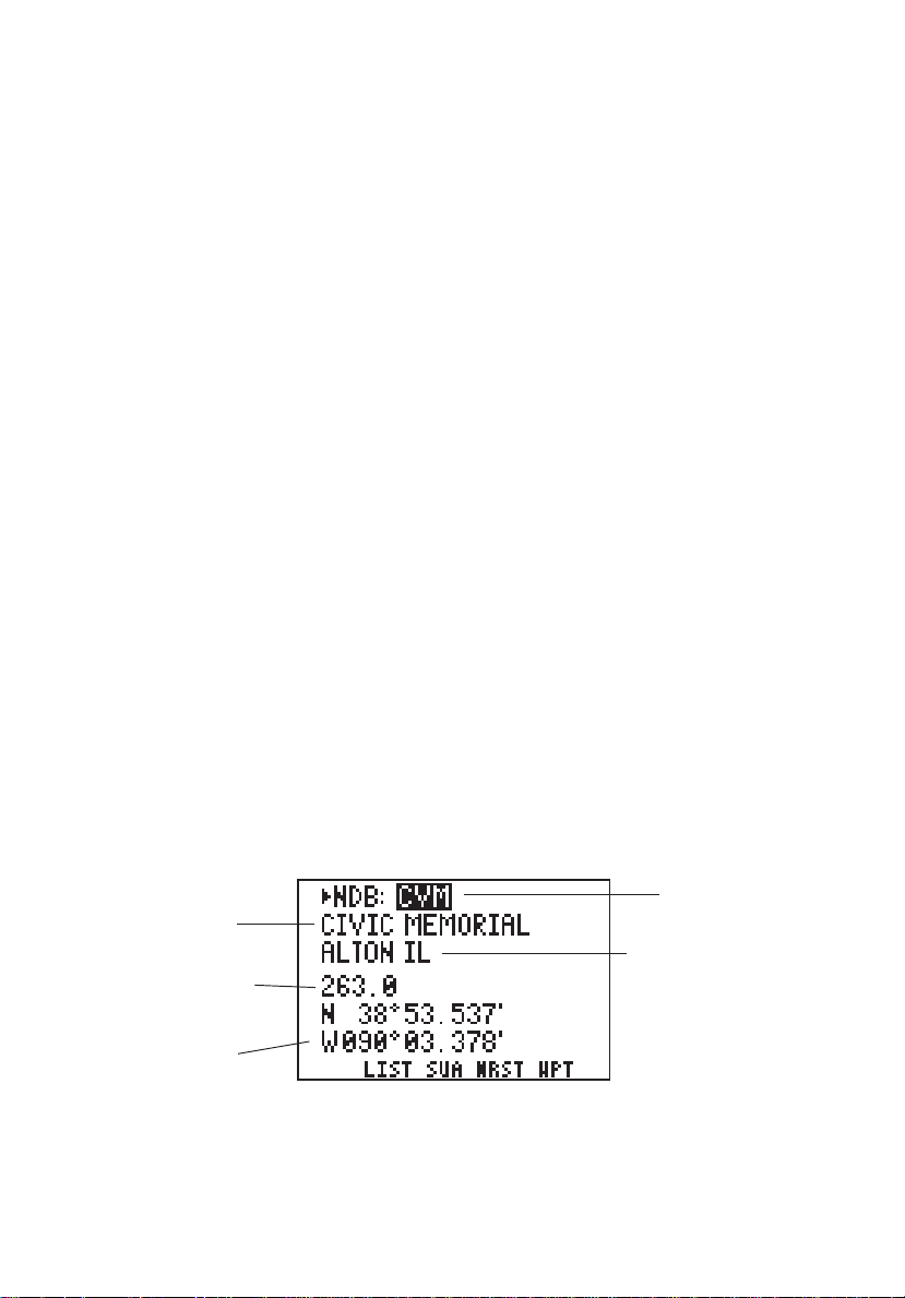
3.4 NDB INFORMATION
1
2
3
4
5
3-7
Page 30
The GPS 95 displays the following information on NDBs:
1) Identifier (selectable)
2) Facility name
3) City/state
4) Frequency
5) Location (latitude/longitude or grid system)
You may select an NDB by its one-to-three-character identifier, facility name
or city/state. (See Section 3.10 for information on selecting NDBs by facility
name or city/state.)
To select an NDB by identifier...
· Press WPT/SUA and, if needed, the WPT softkey to display the
Waypoint Definition Page.
· If “NDB” is not currently displayed in the upper left corner: press the
right arrow key to place the cursor on the cyclic field, then press CLR
(repeatedly) until “NDB” is shown.
· Press the right arrow key to move the cursor to the right of “NDB”.
· Enter the identifier of the desired NDB using the alphanumeric and
arrow keys. Press ENT. The information for the selected NDB is
displayed.
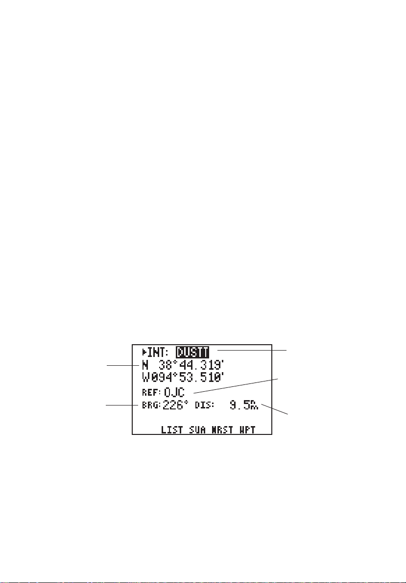
3.5 INTERSECTION INFORMATION
1
2
3
4
5
The GPS 95 features the following information on intersections:
1) Identifier (selectable)
2) Location (latitude/longitude or grid system)
3) Reference VOR identifier
4) Bearing from reference VOR to selected intersection
5) Distance from reference VOR to selected intersection
3-8
Page 31

Intersections are only selected by identifier. Once an intersection is selected,
the identifier of, bearing from, and distance from the nearest VOR will be
displayed. (NOTE: The VOR is simply the nearest facility and is not
necessarily the VOR used to define the intersection.)
To select an Intersection...
· Press WPT/SUA and, if needed, the WPT softkey to display the
Waypoint Definition Page.
· If “INT” for intersection, is not currently displayed in the upper left
corner: press the right arrow key to place the cursor on the cyclic field,
then press CLR (repeatedly) until “INT” is shown.
· Press the right arrow key to move the cursor to the right of “INT”.
· Enter the identifier of the desired intersection using the alphanumeric
and arrow keys. Press ENT. The information for the selected
intersection is displayed.
3.6 USER WAYPOINT INFORMATION
2
1
3
4
5
6
In addition to the airport, VOR, NDB and intersection information that is
already stored in your GPS 95, you may enter an additional 500 locations as
user waypoints.
The GPS 95 will display the following user waypoint information:
1) Waypoint identifier
2) Location (latitude/longitude or grid system)
3) Reference waypoint identifier
4) Bearing from reference waypoint to selected user waypoint
5) Distance from reference waypoint to selected user waypoint
6) User comments
3-9
Page 32

User waypoints are only selected by the identifier that you assign.
To select a user waypoint...
· Press WPT/SUA and, if needed, the WPT softkey to display the
Waypoint Definition Page.
· If “USR”, for user waypoint, is not currently displayed in the upper left
corner: press the right arrow key to place the cursor on the cyclic field,
then press CLR (repeatedly) until “USR” is shown.
· Press the right arrow key to move the cursor to the right of “USR”.
· Enter the identifier of the desired user waypoint using the alphanumeric
and arrow keys. Press ENT. The information for the selected user
waypoint is displayed.
You may select a reference waypoint by moving the cursor to the reference
waypoint identifier field and entering the desired waypoint identifier (airport,
VOR, NDB, intersection or user waypoint).
3.7 CREATING USER WAYPOINTS
When a waypoint identifier has been entered that does not exist in memory
the GPS 95 will assume you wish to create a new waypoint. You may create
a new waypoint using one of two methods: direct position entry (latitude/
longitude or grid system) or relative to an existing waypoint.
In order to create a waypoint by direct position entry the coordinates for the
new waypoint must be known and entered directly into the unit.
To enter the waypoint position directly...
· With the Waypoint Definition Page displayed (and user waypoint
information shown), press the right arrow key until the cursor is over
the waypoint identifier field.
3-10
Page 33

· Enter the identifier of the new waypoint using the alphanumeric and
arrow keys. Press ENT when complete. The cursor will move to the
position coordinates.
· Enter the position of the new waypoint. Press ENT after data is entered
into each field. The number of fields required for position entry will
depend on the position coordinate option selected. (See Section 8.6.)
If latitude and longitude coordinates are selected there will be four
fields if decimal degrees are used - two to define the hemispheres (“N”
or “S”, “E” or “W”) and two to enter the latitude and longitude degrees.
If latitude and longitude coordinates are selected with degrees, minutes
and decimal seconds, there will be eight data entry fields to define the
position since degrees, minutes and seconds are each divided into
their own field. If a grid system is selected it will have a different number
of fields depending on the format of the selected grid.
A new waypoint can be defined relative to another waypoint already
contained within the GPS 95's memory. When creating a new waypoint
relative to an existing waypoint, you will define a distance and bearing from
the existing waypoint to the new waypoint location.
To create a waypoint referenced from an existing waypoint...
· With the Waypoint Definition Page displayed (and user waypoint
information shown), press the right arrow until the cursor is over the
waypoint identifier field.
· Enter the identifier of the new waypoint using the alphanumeric and
arrow keys. Press ENT when complete.
· Press the right arrow key until the cursor is over the reference waypoint
identifier field.
· Enter the identifier of the desired reference waypoint (airport, VOR,
NDB, intersection or user waypoint) and press ENT.
· Enter the bearing from the reference waypoint to the new waypoint
and press ENT. The bearing will be true or magnetic depending on the
unit setups. (See Section 8.6.)
· Enter the distance from the reference waypoint to the new waypoint
and press ENT. The distance will be in nautical miles, statute miles or
kilometers depending on the unit setups. (See Section 8.6.)
3-11
Page 34

Once the waypoint location is created, the user comment field will automatically
be filled with the date and time the waypoint was created. You may enter a
different user comment by placing the cursor over this field and entering the
new comment with the alphanumeric and arrow keys, followed by ENT when
complete.
You may also modify the position of an existing user waypoint from the
Waypoint Definition Page. A user waypoint may be changed using the same
procedures described above for creating a user waypoint, by direct position
entry (latitude/longitude or grid system) or relative to an existing waypoint.
When modifying an existing waypoint, the new position data is entered
directly over the old data. For a given data field, once the ENT key is pressed
the position data is updated. (NOTE: If a waypoint is being used for
navigation, its position cannot be modified. An attempt to modify the position
of such a waypoint will result in the message “Cannot change active
waypoint”.)
3.8 WAYPOINT LIST
The Waypoint List Page allows you to view all stored user waypoints in your
GPS 95. The list may be scrolled, with the arrow keys, to view all the
waypoints. From this page, waypoints may be selected for deletion,
renaming or to activate a GOTO. (See Chapter 4 for information on the
GOTO function.)
To delete a user waypoint...
· Select the Waypoint List Page by pressing WPT/SUA and the LIST
softkey, if needed.
· With the arrow keys, place the cursor on the desired waypoint.
· Press CLR and ENT.
· A confirmation page is displayed. Press ENT to confirm or CLR to
cancel.
3-12
Page 35

NOTE: If you attempt to delete a GOTO or route waypoint, a message will
be displayed. You must cancel the GOTO or delete the route before you can
delete the waypoint. (See Chapter 4 and Section 6.5.)
The Waypoint List Page also gives you the option of deleting all user
waypoints at one time.
To delete all user waypoints...
· Select the Waypoint List Page by pressing WPT/SUA and the LIST
softkey, if needed.
· With the arrow keys, place the cursor over “Delete ALL?” and press
ENT.
· A confirmation page is displayed. Highlight "yes" and press ENT to
confirm the deletion of all waypoints or press CLR to cancel.
NOTE: The “Delete All?” selection will delete all routes as well.
From the Waypoint List Page you may also change the name of any user
waypoint.
To rename a user waypoint...
· Select the Waypoint List Page by pressing WPT/SUA and the LIST
softkey, if needed.
· With the arrow keys, place the cursor on the desired waypoint.
· Type in a new name for the waypoint and press ENT.
· A confirmation page is displayed. Press ENT to confirm the name
change or CLR to cancel.
3.9 USING WAYPOINTS
You may use waypoints on many GPS 95 pages. A waypoint is selected by
entering its identifier and pressing ENT. Some waypoints in the database
may have the same identifier. When you have entered a waypoint name that
is not unique, the Duplicate Waypoint Page will be displayed for you to select
the desired waypoint.
3-13
Page 36

The waypoint identifier and number of duplicates are displayed on the first
line of the Duplicate Waypoint Page. On the following lines, the waypoint type
and region for each duplicate waypoint is displayed, sorted by distance from
present position. From this list you may select the desired waypoint by
placing the cursor on the desired waypoint, using the arrow keys, and
pressing ENT.
3.10 USING WAYPOINTS BY SCANNING
The GPS 95 offers a waypoint scanning feature which will simplify waypoint
entry. Airports, VORs and NDBs may be scanned by identifier, city or facility
name. Intersections and user waypoints can only be scanned by identifier.
To select a waypoint by scanning identifiers...
· On a blank waypoint identifier field press the WPT/SUA key. (If the
identifier field is not blank, press CLR first.) The Scan Page will be
displayed and the cursor will be on a cyclic field.
· Select the desired waypoint category (airport, VOR, NDB, intersection
or user) by pressing CLR (repeatedly).
· Press the right arrow key once to place the cursor on the waypoint
identifier field.
· Enter the starting letter, or letters, of the waypoint identifier. You may
limit the scan to the level that you desire. For example, if you enter “K”
the GPS 95 will scan through all waypoints (for the selected category)
that begin with the letter “K”; but, if you enter “KIA” the GPS 95 will
display only those waypoints that begin with “KIA”.
3-14
Page 37

· Press WPT/SUA to begin scanning.
· Press the right arrow key to sequence through the available waypoints.
If you pass the desired waypoint, you may press the left arrow key to
scan backwards through the list.
· Once the desired waypoint is selected, press ENT to accept the
waypoint and complete the scan. The GPS 95 will revert to the page
that you were on prior to scanning. The selected waypoint will be
displayed on the waypoint identifier field.
To select a waypoint by scanning city names...
· On a blank waypoint identifier field press the WPT/SUA key. (If the
identifier field is not blank, press CLR first.) The Scan Page will be
displayed and the cursor will be on a cyclic field.
· Select the desired waypoint category (airport, VOR or NDB only) by
pressing CLR (repeatedly).
· Press the right arrow key three times to place the cursor on the city/
state field.
· Enter the starting letter, or letters, of the desired city. You may limit the
scan to the desired level by designating the number of starting letters
(as described above when scanning by identifier). There is no need
to designate the state. Once the scan begins the appropriate state will
be displayed automatically.
· Press WPT/SUA to begin scanning.
· Press the right arrow key to sequence through the available waypoints.
If you pass the desired waypoint, you may press the left arrow key to
scan backwards through the list.
· Once the desired waypoint is selected, press ENT to accept the
waypoint and complete the scan. The GPS 95 will revert to the page
that you were on prior to scanning. The selected waypoint will be
displayed on the waypoint identifier field.
To select a waypoint by scanning facility names...
· On a blank waypoint identifier field press the WPT/SUA key. (If the
identifier field is not blank, press CLR first.) The Scan Page will be
displayed and the cursor will be on a cyclic field.
3-15
Page 38

· Select the desired waypoint category (airport, VOR or NDB only) by
pressing CLR (repeatedly).
· Press the right arrow key twice to place the cursor on the facility name.
· Enter the starting letter, or letters, of the facility name. You may limit
the scan to the desired level by designating the number of starting
letters (as described previously when scanning by identifier).
· Press WPT/SUA to begin scanning.
· Press the right arrow key to sequence through the available waypoints.
If you pass the desired waypoint, you may press the left arrow key to
scan backwards through the list.
· Once the desired waypoint is selected, press ENT to accept the
waypoint and complete the scan. The GPS 95 will revert to the page
that you were on prior to scanning. The selected waypoint will be
displayed on the waypoint identifier field.
NOTE: When duplicate entries exist for the selected item (identifier/city/
facility name), the additional entries may be viewed by continuing to press
the arrow keys until the desired waypoint is selected.
3.11 REVIEWING WAYPOINTS
The GPS 95 allows you to quickly review waypoint information without
entering the waypoint identifier. For example, you may review information
regarding the waypoints in a route, or review the definition of the nearest
waypoints. In general, if the cursor is over a waypoint identifier, you may
quickly review the information about that waypoint.
To review a waypoint definition...
· Place the cursor over a waypoint identifier (using the arrow keys) and
press ENT. The Waypoint Definition Page is displayed indicating the
category of waypoint shown.
3-16
Page 39

· If the waypoint is an airport, a second cyclic field will appear in the
upper right corner of the page. You may select between location
(Locn), communication (Comm) or runway (Rnwy) information by
highlighting this cyclic field and pressing CLR until the desired
information is displayed.
· With the cursor over “OK?”, press ENT to exit the review process and
return to the previous page.
3.12 NEAREST WAYPOINTS
An important feature on the GPS 95 is the ability to display up to nine nearest
waypoints (of each category) within 200 nautical miles of your present
position. The bearing and distance to each nearest waypoint is also
displayed. The nearest waypoint feature can be critical in finding a safe
landing location in the event of an in-flight emergency.
To view nearest waypoint information...
· Select the Nearest Waypoint Page by pressing WPT/SUA and the
NRST softkey, if needed.
· Place the cursor key on the cyclic field in the upper left corner of the
page using the arrow keys.
· Select the desired waypoint category by pressing CLR. The five
nearest waypoints for that category will be displayed, along with the
bearing and distance to each.
· Use the arrow keys to scroll through the list and view additional nearest
waypoints (up to nine).
Keep in mind that you may view additional information for any nearest
waypoint by placing the cursor on the waypoint identifier and pressing ENT.
In the case of a nearest airport; facility name, elevation, fuel services,
communication frequencies, and runway information are all instantly available.
(See Section 3.11.)
3-17
Page 40

The nearest waypoint feature can be used in conjunction with the GOTO key
to provide instantaneous navigation information to a nearby waypoint.
Simply place the cursor over the desired nearest waypoint identifier and
press GOTO, followed by ENT. The GPS 95 will immediately plot a course
from your present position to the nearby waypoint. (See Chapter 4 for more
information on the GOTO key.)
3.13 SUA PAGE AND MESSAGES
The GPS 95 provides four different SUA messages (alerts) depending on
your location relative to a special-use airspace. These SUA messages are
only given when the SUA alarms are on and when your ground speed
exceeds 30 knots. (See Section 8.10 for more information on SUA alarms.)
First, if your projected course will place you in an SUA within the next ten
minutes, you will be alerted with an “SUA Ahead < 10 min” message.
Second, if you are within two nautical miles of an SUA and projected to enter
it, an “SUA Near & Ahead” message will appear. If an SUA is within two
nautical miles of your position, but you are not projected to enter it, an “SUA
Near < 2 nm” message is provided.
Finally, when entering an SUA, the GPS 95 will alert you with an “Inside SUA”
message.
NOTE: The term “SUA” is used to describe both special-use and controlled
airspaces.
3-18
Page 41

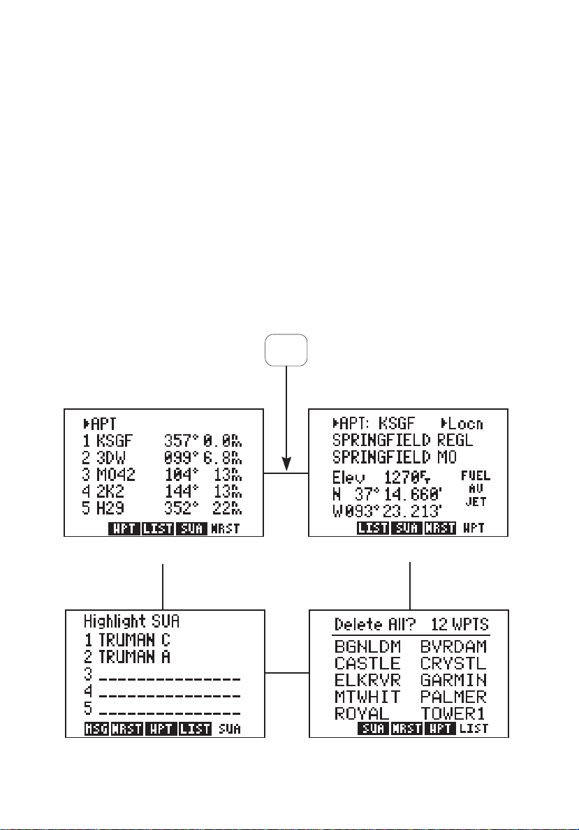
You may view additional information for each SUA / controlled airspace for
which a message is provided by utilizing the SUA Page. The SUA page lists
any SUA you are within, near or that lies ahead (less than ten minutes away).
For SUAs that lie ahead of you, the estimated time en route (ETE) before
entry may also be displayed. Additional information, such as airspace type,
floor/ceiling limits and controlling agency, may be displayed by selecting the
desired airspace.
To view additional SUA information...
· Press the WPT/SUA key to select
the SUA Page.
· Using the arrow keys, highlight
the desired SUA. The top line of
the SUA Page will change from
“Highlight SUA” to “Inside”,
“Ahead”, “Near” or "Near & Ahead".
If the SUA lies “Ahead”, estimated
time en route to that SUA's boundary
will appear in the upper right corner
of the page.
· Press ENT. Additional information
appears describing the type of
airspace, controlling agency and
floor/ceiling limits.
ENT
· Press ENT again to return to the
SUA page.
NOTE: For Class B / CTA and Class C/
TMA airspaces, the SUA Page provides
additional information for each sector
you are in, near, or that lies ahead.
3-19
Page 42

CHAPTER 4
GETTING THERE FAST - GOTO
The GOTO function allows you to quickly set a course from your position to
any waypoint.
To activate the GOTO function...
· Press GOTO. The GOTO Page will be displayed with the cursor on
the GOTO waypoint field. If the GPS 95 is currently navigating to a
waypoint, that waypoint will be offered as the default GOTO waypoint.
· Enter the name of the destination waypoint. If a waypoint is shown and
it is not the desired destination, type the new name right over the old
name. (NOTE: If a non-existent waypoint name is entered, the GPS
95 will assume that this is a new user waypoint and will display a blank
Waypoint Definition Page where you may enter the new waypoint's
coordinates.)
· Confirm the GOTO waypoint by pressing ENT. The Navigation
Summary Page will be displayed with the D-bar on the CDI centered.
(See Section 5.1 for more information on the Navigation Summary
Page and the CDI.)
You may also select the desired GOTO waypoint identifier by scanning. If
the desired waypoint is an airport, VOR or NDB; you may scan by city or
facility name (as well as identifier) to select the desired GOTO waypoint
identifier. (See Section 3.10 for more information on waypoint scanning.)
Alternatively, the GOTO function may be quickly activated from any page
(e.g., the Nearest Waypoint Page or the Waypoint List Page) by placing the
cursor over the desired waypoint name and pressing GOTO. The GOTO
Page will be displayed with the cursor on the GOTO waypoint name. The
GOTO function will be activated when the ENT key is pressed.
4-1
Page 43

You may cancel the GOTO function at any time.
To cancel the GOTO function...
· Press GOTO. The GOTO Page will be displayed.
· Press CLR. The GOTO waypoint name will become blank.
· Press ENT. The GPS 95 will start to navigate using the active route,
if it has been programmed. (See Chapter 6.) Otherwise, the GPS 95
will stop computing waypoint navigation data.
4-2
Page 44

CHAPTER 5
NAVIGATION INFORMATION
The GPS 95 features four navigation pages. You may select the desired
page by pressing NAV and, if needed, the appropriate softkey.
Navigation Summary Page
Map Display
5.1 NAVIGATION SUMMARY PAGE
GOTO or
Active Leg
Field #1
Field #3
CDI
Present Position Page
Map Configuration Page
Field #2
Field #4
Relative Bearing
Pointer
5-1
Page 45

The Navigation Summary Page displays direction, distance and speed
information to guide you along a route or to a GOTO destination. Included
is a graphic course deviation indicator (CDI), at the bottom of the page, which
illustrates your position relative to the course. The current CDI scale setting
is shown at each end of the CDI scale. (See Section 8.11 for information on
setting the CDI scale.) A relative bearing pointer at the center of the CDI
indicates the bearing to the waypoint relative to the current ground track
(TRK). In the example shown, the current ground track is 347 degrees and
the bearing to our destination is 339 degrees. The relative bearing pointer
points slightly to the left indicating that our destination is ahead, but slightly
to the left of our current direction of travel.
At the top of the Navigation Summary Page the current GOTO destination is
displayed, or the “active leg” of a route when using the GPS 95’s route
navigation features. (See Chapter 6 for information on route navigation.)
During the process of acquiring satellites, the GPS 95 will not provide
navigation data. The top line of the Navigation Summary Page will indicate
this condition, as illustrated below.
If the GPS 95 has acquired satellites, but is not navigating to a waypoint (i.e.,
no GOTO destination or route has been activated), the top line of the
Navigation Summary Page will indicate that no destination has been defined,
as illustrated below.
5-2
Page 46

Notice that the Navigation Summary Page has four cyclic fields. With these
cyclic fields you may configure your GPS 95 to display navigation information
according to your preferences. (See Appendix B for a description of
navigation terms.) The field options are as follows:
Field #1 (top left)
· Bearing to destination waypoint (BRG)
· Course to steer (CTS)
· Desired track (DTK)
· Ground track (TRK)
· Off course error, or turn angle (TRN)
Field #2 (top right)
· Distance to destination waypoint (DIS)
· Cross track error (XTK)
· VNAV altitude (V)
Field #3 (bottom left)
· Ground track (TRK)
· Ground speed (GS)
Field #4 (bottom right)
· Ground speed (GS)
· Estimated time of arrival (ETA)
· Estimated time enroute (ETE)
5.2 MAP DISPLAY
Map Orientation
Scale Distance
Ground Speed
Present Position
Scale Setting
5-3
Page 47

The GPS 95 also features a Map Display which shows a graphic top view of
your location. The current ground speed is indicated at the top right corner
of the display. The top left corner defines the orientation of the Map Display:
“North up”, “Track up”, or “Desired track up.” If “000” is shown, the Map
Display is oriented “North up.” (See Section 5.3 for selection of Map Display
orientation.) Your present position is shown in the middle of the display. If
the Map Display is oriented “Track up” your present position is indicated by
an aircraft symbol. If either “North up” or “Desired track up” orientations are
selected, the present position is indicated by a crosshair (“+”).
VOR
Airspace
Boundaries
Nearest Airport
(showing runways)
Intersection
Airport
NDB
You may select which items you wish to display. The Map Display can
provide the fifteen nearest waypoints of each category: airport, VOR, NDB,
intersection, and user. GOTO or route waypoints which are not part of the
fifteen nearest waypoints will also be displayed. The Map Display can draw
the boundaries of nearby special-use / controlled airspaces. The track
history and/or the active route may also be shown as solid lines on the
display. Selection of which items to display is performed on the Map
Configuration Page. (See Section 5.3.)
You may view the identifier for any waypoint on the Map Display by moving
the cursor over that waypoint (with the arrow keys). By moving the cursor
around the page you can identify each waypoint shown. Keep in mind that
when the cursor is over a given waypoint you may review information about
that waypoint by pressing ENT, or plot a course to that waypoint by pressing
GOTO. (HINT: When viewing waypoint identifiers you may quickly return the
cursor to the lower right corner by pressing CLR.)
The scale distance for the screen (distance represented by the height of the
screen) is at the lower left corner of the screen. The scale setting number
(bottom right corner) may be changed to select the desired scale distance.
You may zoom in to a .5 nautical mile scale, or out to a maximum scale of 240
nautical miles.
5-4
Page 48

To set the Map Display scale...
· With the cursor on the scale setting number, press CLR to sequence
through the available scale settings. (HINT: The scale setting may
also be selected by pressing the alphanumeric key that corresponds
to the desired scale.)
5.3 MAP CONFIGURATION
The Map Configuration Page allows you to tailor the GPS 95’s Map Display
to your preferences. As previously stated, the Map Display can show
airports, NAVAIDs, user waypoints, airspace boundaries, the active route,
your track history and/or waypoint identifiers. Any of these items may be
turned on or off according to your preferences. For example, when the Map
Display is zoomed out to its maximum levels the screen may appear too
cluttered to be easily read. In this case, you could turn off the information not
needed to create a more legible display.
NOTE: The "Other" airspaces selection includes Alert, Caution, Danger,
Training and Warning areas.
To turn display information on/off...
· Press NAV and the CFG softkey, if needed, to select the Map
Configuration Page.
· Place the cursor on the desired item using the arrow keys.
· Press CLR to toggle between “on” and “off”.
· If you wish to return to the Map Display: place the cursor on the page
options using the arrow keys, then press the MAP softkey.
5-5
Page 49

An auto zoom feature is provided for automatic scaling of the Map Display.
With this feature on, the scale setting will automatically adjust as you
approach your destination. Starting at 80 nautical miles during en route flight,
the Map Display will zoom in progressively, stopping at a one nautical mile
scale as you arrive at your destination. (When navigating via a route, the
scale will begin at a maximum 80 nautical miles en route setting and zoom
in to one nautical mile at each waypoint along the route. As you cross over
each interim waypoint, the Map Display will zoom back out to no more than
80 mautical miles.)
The Map Display orientation is also selected from the Map Configuration
Page. The Map Display may be oriented as follows:
· North up - The Map Display will always be displayed with north as the
top of the page.
· TRK up - Track up. The Map Display will be oriented such that your
current ground track direction is at the top of the page.
· DTK up - Desired track up. The Map Display will be oriented along
the course between the “active from” and “active to” waypoints.
5.4 PRESENT POSITION
As mentioned earlier, the Present Position Page is automatically displayed
when the GPS 95 is turned on and a position is obtained. The top line of this
page displays your ground track (TRK) and ground speed (GS). The next two
lines indicate your current position according to the coordinate format and
map datum selected. In the example shown above, the position is displayed
in degrees and decimal minutes of latitude/longitude. (See Section 8.6 for
more information on coordinate format selections and Section 8.7 for more
information on map datum selections.)
The bottom line of the Present Position Page is a cyclic field which can
display either altitude above mean sea level (MSL) or current time (UTC or
local). Select the desired option by placing the cursor on this field and
pressing CLR.
5-6
Page 50

When the GPS 95 is performing 2D navigation, the last known altitude will be
used to calculate a present position. If the altitude is not accurate within a few
hundred feet you should manually enter your altitude.
To enter the altitude (2D only)...
· Use the arrow keys to place the cursor to the right of “Altitude”.
· Enter the correct altitude and press ENT.
During the initial satellite acquisition, the displayed position is the last known
position stored in the GPS 95. If your position has moved over one thousand
miles since the unit was last used, you may want to select AutoLocate mode.
(See Section 8.5.) Alternatively, you may enter a more accurate initial
position directly on the Present Position Page to speed up the acquisition
process. (You may also change the position at any time while you are in
simulator mode.)
5.5 SAMPLE TRIP
Your new GPS 95 is really very simple to operate. For the purpose of this
demonstration it is assumed that the factory default settings, including the
selection of nautical units (knots, nautical miles, feet), have not been
changed. If these settings have been changed, the unit may display different
data than that presented here. (See Chapter 8 on unit setups.)
ENT
Turn the GPS 95 on. The unit will
display the welcome screen and
perform several diagnostic checks to
ensure that proper operation will occur.
The Database Page will be displayed
showing the cycle, effective date and
expiration date of the database.
Review the database information and
press ENT to approve the information.
5-7
Page 51

Since this is a simulated trip, you will select the simulator mode and indicate
a starting location for the trip. Your simulated trip will begin at an intersection
called LENEX in Lenexa, Kansas. (NOTE: This sample trip assumes that
the Americas database is used. If you are using the International database
follow the general steps outlined in this sample trip, but substitute waypoints
from your area of interest.)
To select simulator mode and define a starting location...
ABC
1
Press the MENU softkey (the “1” key,
in this case) to display the Menu Page.
Place the cursor on “Setups” using the
ENT
right arrow key and press ENT.
5-8
The Operational Setup sub-menu is
displayed with “Operation Mode”
highlighted.
Press ENT to select “Operation Mode”.
ENT
Page 52

The Operating Mode Page is displayed
showing the current operational mode.
Place the cursor on the operational
mode field using the right arrow key.
CLR
*Repeat until desired
mode is selected
ENT
JKL
4
*Press alphanumeric and
DEF
2
arrow keys, as needed, to
select desired identifier
Press CLR until “Simulator?” is
selected.
Press ENT to accept simulator mode.
The cursor is now on the reference
waypoint identifier. The intersection,
LENEX, will be entered here using the
alphanumeric keys.
Press the “4” key, followed by the right
arrow key to select the letter “L”.
Press the “2” key to select the letter
“E”.
Continue pressing the desired
alphanumeric keys and, if needed, the
arrow keys to enter the “LENEX”
intersection. Press ENT when
complete.
5-9
Page 53

ENT
The cursor is over the reference
bearing. Since the simulation will begin
ENT
at LENEX you do not need to define a
reference bearing from this point.
Press ENT.
ENT
The cursor is over the reference
distance with zero shown. Press ENT.
NAV
*Plus POSN softkey
if needed
The initial position is now set at the
LENEX intersection.
You can view your position coordinates
by pressing NAV and the POSN
softkey, if needed. The Present
Position Page is displayed.
From your starting location at the “LENEX” intersection you may plot a course
and navigate to a nearby airport. For this sample trip you will fly to KCOU,
Columbia Regional Airport.
To select a destination waypoint...
GO
TO
5-10
Navigating to a waypoint is easy. Press
GOTO and the GPS 95 will display the
GOTO Page, as illustrated. Notice
that the cursor is to the right of “GOTO”.
On this field you will enter the identifier
of your destination waypoint, KCOU.
Page 54

JKL
ABC
4
Press the “4” key to select the letter
“K”.
1
Press the “1” key followed by the right
arrow key to select the letter “C”.
*Press the alphanumeric
and arrow keys as
needed to select desired
ENT
identifier
Continue pressing the desired
alphanumeric keys and, if needed, the
arrow keys to enter the KCOU airport
identifier. Press ENT when complete.
The Navigation Summary Page is
displayed showing naviation
information for your trip to KCOU.
The GPS 95's simulator mode allows you to enter a ground speed which is
used to animate the navigation displays.
To enter a simulated speed...
Press the left arrow key to place the
cursor on the ground speed field (bottom
right).
ABC
1
*Press the alphanumeric
keys as needed to enter
ground speed
ENT
Enter a ground speed of 150 knots.
Begin by pressing the “1” key. Continue
pressing the alphanumeric keys until
“150” is displayed. Press ENT when
finished.
The GPS 95 now displays additional
navigation information as it simulates
a flight to KCOU. Notice the information
changing as the flight progresses.
5-11
Page 55

Additional information is available from the Navigation Summary Page. You
may recall from Section 5.1 that this information is viewed by highlighting one
of the four cyclic fields and pressing CLR. Let's take a look at one of those
fields now.
To view additional navigation information...
Press the left arrow key twice to place
the cursor on the fourth cyclic field
(bottom right).
CLR
CLR
Press CLR to select “ETA”. This field
will now show at what time (UTC) you
will arrive at Columbia Regional Airport.
Press CLR again to select “ETE”. This
field now indicates how long it will take
(in minutes and seconds for this
example) to reach Columbia Regional
Airport. (Hint: To return to “GS”, press
CLR one more time.)
5-12
Page 56

The GPS 95's Map Display is also useful to help “orient” yourself. The Map
Display can show area airports, NAVAIDS, and intersections as points of
reference.
To view the Map Display...
NAV
DEF
2
Press NAV and the MAP softkey.
The Map Display is shown indicating
your position at the center of the screen
and nearby waypoints. (Section 5.3
covers the Map Configuration Page
and shows what types of information
are available on the Map Display.)
*Continue pressing
CLR until desired
CLR
scale is selected
Press CLR (repeatedly) to select the
desired scale.
The simulated trip has demonstrated only a small portion of the GPS 95's
many features. Take a moment to experiment with your new unit. Review
this chapter, covering types of information on the Navigation Summary Page
and the Map Display. Look at waypoint and airspace information by taking
another glance at Chapter 3. Read Chapter 6 to learn more about routes.
Customize the GPS 95 according to your preferences as described in
Chapter 8.
5-13
Page 57

CHAPTER 6
ROUTES
KSTL
KTUL
(Active from waypoint)
SGF
EOS
MAP
Active Leg
(Active to waypoint)
The GPS 95 offers a route navigation feature for you to navigate along a predefined sequence of waypoints.
The GPS 95 route capability allows you to create and store twenty routes,
numbered 0 through 19, containing up to 30 waypoints each. Routes 1 to 19,
the storage routes, can be activated to travel either in the order you entered
the waypoints or in reverse order. Route 0, the active route, is the route you
are navigating. The waypoint toward which you are navigating is called the
“active to” waypoint. The waypoint immediately behind you is called the
“active from” waypoint. The line that connects the “active from” and “active
to” waypoints is called the “active leg.”
The GPS 95 features automatic leg selection which will select the route
segment closest to your position as the active leg. The GPS 95 also features
automatic leg sequencing. As you pass a waypoint in the route, the unit will
automatically select the next waypoint as the “active to” waypoint.
6-1
Page 58

There are 3 route pages. You may select the desired page by pressing RTE
and, if needed, the appropriate softkey.
Route Definition Page
Active Route Page
Route List Page
6.1 ROUTE DEFINITION
The Route Definition page allows you to create, change, review, copy, and
activate routes. Remember that route 0 is always the active route. If you
create a route in route 0, you should copy it into an empty storage route (1-
19). When you activate a storage route, it will be copied to route 0 for
activation.
Route # Field Route Action Field
Desired
Track
Waypoint List
6-2
Leg Distance
Page 59

On the route number field, you may choose between routes 0 through 19 with
CLR. Next to this is a route action field which allows you to activate the route,
clear the route, copy the route to another location, or invert the order of the
waypoints in a route and activate it. The arrow keys allow you to scroll
through the list of waypoints in a route.
6.2 CREATING AND COPYING ROUTES
The Route Definition Page allows you to create new routes and to copy a
route to another location for later reference.
To Create a Route...
· Press RTE and, if needed, the
RTE softkey to display the Route
Definition Page.
· Move the cursor to the route
number field and press CLR until
you find an empty route. (HINT:
Although the route number field is
a cyclic field, to speed selection
you may also enter the desired
route number using the
alphanumeric keys.)
· Place the cursor on the first blank waypoint name field using the arrow
keys and type in a waypoint you wish to put in the route.
· Press ENT
· Repeat this process for each waypoint you want to add, up to a total
of 30.
To copy a route...
· Press RTE and, if needed, the
RTE softkey to display the Route
Definition Page.
· Highlight the route number field
with the cursor and select the route
number to copy from with CLR.
· Highlight the route action field with the arrow keys and press CLR until
“Copy To” is displayed.
· A third field now appears in the top right corner. Highlight this field and
select the destination route number with CLR.
· Press ENT. The route is now copied.
6-3
Page 60

6.3 ACTIVATING AND INVERTING ROUTES
Routes are also activated on the Route Definition Page. You may activate
any route in the displayed order, or in reverse order. (NOTE: Remember,
when a new route is activated, the previous contents of route 0 will be
overwritten. If you wish to save route 0, be sure to copy it to an empty route
first.)
To activate a route...
· Press RTE and, if needed, the
RTE softkey to display the Route
Definition Page.
· Highlight the route number field
with the cursor and select the route
number to activate with CLR.
· Highlight the route action field, and with CLR select “Activate?”.
· Press ENT to activate the route.
To invert a route...
· Follow the same steps as above
for activating a route, but select
“Invert?” at the route action field.
· Press ENT to activate the route in
an inverted order.
6.4 EDITING ROUTES
Existing routes may be edited from the Route Definition Page.
To Edit an Existing Route...
· Press RTE and, if needed, the
RTE softkey to select the Route
Definition Page.
· Highlight the route number field
with the cursor and select the route
you wish to edit.
6-4
Page 61

· To insert a waypoint into the route:
highlight the waypoint you want to
place the new waypoint in front of,
type in the new waypoint name
and press ENT. The new waypoint
is added to the route.
· To delete a waypoint from the
route: highlight the waypoint you
wish to delete, press CLR and
ENT.
· If you attempt to add a waypoint to a route that already contains 30
waypoints, you will be informed with the message, “Route is Full”.
NOTE: You may also edit a route from the Active Route Page. (See Section
6.6.)
6.5 DELETING ROUTES
You may delete an unwanted route from the Route Definition Page.
To delete a route...
· Highlight the route number field
and select the route you wish to
delete with CLR.
· Highlight the route action field and
select “Clear?” with the CLR key.
· Press ENT to delete the route.
6.6 ACTIVE ROUTE
Active Leg
Distance
Waypoint List Cyclic Column:
- ETE
- ETA
- DTK
The Active Route Page displays the waypoints of the active route starting
with the “active from” and “active to” waypoints on the top line. Press the
ACTV softkey to select this page.
6-5
Page 62

The waypoint list displays route waypoints starting with the “active to”
waypoint. For each waypoint, additional information is available. The first
column displays Distance (DIS). The second column is a cyclic field that
displays Estimated Time Enroute (ETE, in hours/minutes or minutes/seconds,
as appropriate), Estimated Time of Arrival (ETA), or Desired Track (DTK).
You may scroll through the waypoint list with the arrow keys.
To edit the active route...
· To insert a waypoint: highlight the waypoint you want to place the new
waypoint in front of, type in the new waypoint name and press ENT.
The new waypoint is added to the route.
· To delete a waypoint: highlight the waypoint you wish to delete, press
CLR and ENT.
6.7 ROUTE LIST
The Route List Page displays a list of all routes currently stored in memory.
Press the LIST softkey to select this page. The Route List Page displays the
route numbers (far left), beginning waypoint, and final destination waypoint.
You may also activate or delete a route from the Route List Page.
To Activate a Route...
· Highlight the route you wish to activate with the arrow keys.
· Press ENT. The Route Definition Page is displayed with the “Activate?”
action highlighted.
· Press ENT to activate the route.
To Delete a Route...
· Highlight the route you wish to delete using the arrow keys. Press
CLR. The Route Definition Page is displayed with the “Clear?” action
highlighted.
· Press ENT to delete the route.
6-6
Page 63

CHAPTER 7
AUTOSTORE
TM
The AutoStore function allows you to capture your position at the touch of a
button for future reference. This function saves your current position as a
waypoint. Additionally, you may record your navigation path by inserting the
captured waypoints directly into a route.
The AutoStore Page displays the waypoint identifier, captured position and
optional storage route. An AutoStore waypoint name is pre-assigned as a
three digit number. You may change this to any name you desire. AutoStore
waypoints may be used for any waypoint operation and will be part of the 500
available user waypoints.
7.1 CREATING WAYPOINTS WITH AUTOSTORE
Captured
Position
Waypoint
Identifier
Route Storage
Number
7-1
Page 64

You may capture and save your position as a waypoint, without adding it to
a route, by leaving the route storage number field blank.
To capture present position ...
· Press AUTOSTO. The pre-assigned waypoint identifier and captured
position are displayed. (NOTE: The AutoStore location is captured as
soon as you press AUTOSTO. This allows you all the time you need
to change the waypoint name and/or confirm the AutoStore operation.)
· If you wish to assign a different identifier to the waypoint: move the
cursor to the waypoint name field, enter the name of your choice and
press ENT. If you enter a waypoint name already used, you will be
informed with the message, “WPT Exists _____” (where the blank will
be filled in with the waypoint identifier). Enter a different identifier if this
occurs.
· Press ENT on a blank route storage number field to save the waypoint.
(If the route storage number field is not blank, the waypoint will also be
added to the route shown.)
7.2 BUILDING ROUTES WITH AUTOSTORE
The GPS 95’s AutoStore feature may also be used to build a route as you are
flying. During your flight; as you reach each airport, NAVAID, landmark, or
turn to a new heading; you may capture your position and add it to a route.
Once you reach your destination you can then invert the route and follow the
same course back to where you started. Or, you may want the route for future
reference if you wish to make the same flight again.
To build a route with AutoStore...
7-2
Page 65

· From the starting location, press AUTOSTO to capture the position.
(NOTE: The unit must be in 2D or 3D navigation mode when capturing
your starting position. If the unit is still acquiring satellites, and you
press AUTOSTO, the last known position will be captured and saved.)
· If you wish to assign a different identifier to the waypoint: move the
cursor to the waypoint name field, enter the name of your choice and
press ENT. If you enter a waypoint name already used, you will be
informed with the message, “WPT Exists _____” (where the blank will
be filled in with the waypoint identifier). Enter a different identifier if this
occurs.
· Select a route to store the waypoint in by highlighting the route storage
number field and pressing CLR until the desired route number is
displayed. If the selected route is not empty, the AutoStore waypoint
will be added to the end of the existing route. (HINT: Although the route
storage number field is a cyclic field, to speed selection you may also
enter the desired route number using the alphanumeric keys.)
· Press ENT to add the waypoint to the selected route.
· Repeat these steps each time you arrive at a location you wish to add
to the route, up to a total of 30 waypoints per route.
7-3
Page 66

CHAPTER 8
GPS STATUS AND MENU PAGES
The GPS 95 contains a vast array of functions, many of which you may
custom tailor to your preferences. Additionally, the unit can provide current
status information regarding the satellites being received and display
messages relevant to your current operations. You may select the desired
page by pressing PWR/STAT and, if needed, the appropriate softkey.
Main Menu
Satellite Skyview Page Satellite Status Page
Bar Graph Page
8-1
Page 67

8.1 BAR GRAPH PAGE
The GPS 95 continually monitors the
status of the satellites it tracks and
shows that information graphically on a
Bar Graph Page. Satellite numbers (1-
32) are represented along the bottom of
the graph; signal strength (1 to 9,
weakest to strongest) is represented
along the side. Once a satellite is
received, a bar is displayed showing
signal strength for that satellite. If a satellite is visible, but not being received,
the signal strength will be blank.
The receiver status is also shown at the top of the page. In this example, the
unit is acquiring satellites. The following is a list of possible receiver status
messages:
“Searching the Sky” The GPS 95 is in the process of searching the
sky for visible satellites. You will also be
informed of this condition with a “Searching
the Sky” message.
“Acquiring Satellites” The GPS 95 is in the process of acquiring
visible satellites.
“2D Navigation” The GPS 95 is in the 2D navigation mode.
The unit will calculate a horizontal position,
but not altitude.
“3D Navigation” The GPS 95 is in the 3D navigation mode and
will calculate altitude
“Simulating Navigation” The GPS 95 is in the simulator mode. This
mode should be used only for practice and trip
planning. Never use this mode for actual
navigation.
“Poor Coverage” The GPS 95 is unable to acquire sufficient
satellites for navigation.
“Need Altitude” The GPS 95 needs altitude in order to start
and/or continue 2D navigation. Go to the
Present Position Page and enter the altitude.
(See Section 5.4.)
8-2
Page 68

“Not Usable” The GPS 95 is unusable (possibly due to
incorrect initialization data or abnormal satellite
conditions). Turn the unit off and back on.
When operating with an RTCM input
selected, the Bar Graph Display will
denote each satellite for which
differential corrections are available
with a “D” at the bottom of the bar.
(See Section 8.12 for more information
on RTCM input selections.)
Furthermore, the differential navigation
status will also display at the top of the
page. There are two additional receiver status messages available when
using an RTCM input:
“2D Nav - Diff” The GPS 95 has calculated a differentially-
corrected horizontal position. Altitude has not
been corrected.
“3D Nav - Diff” The GPS 95 has calculated a differentially-
corrected position, including altitude.
8.2 SATELLITE STATUS PAGE
The Satellite Status Page shows the ID,
azimuth, elevation, and signal quality of
each visible satellite in a table format.
The receiver status, again, is displayed
at the top of the screen. The second line
displays two system quality values dilution of precision (DOP) and estimated
position error (EPE). EPE and DOP are
advisory information only and are not to
be used as absolute measures of accuracy. (See Appendix B for definitions
of these terms.)
8-3
Page 69

8.3 SATELLITE SKYVIEW PAGE
s
l Naavv
g
O
Trraacc
k Loogg
U
n
The Satellite Skyview Page shows the
azimuth and elevation of each visible
satellite in a graphic sky view format.
Additionally, DOP and EPE values are
shown on the right hand side of the
page. The display is always oriented
“north up” and is useful in determining
whether a satellite signal is being
blocked by part of the aircraft, buildings,
mountains, or other obstructions. Satellite elevation is indicated by the
distance (of a given satellite) from the center of the display. The center
represents directly overhead, or 90° elevation. The inner ring represents 45°
elevation and the outer ring is the horizon, or 0° elevation. If a satellite is not
currently being received, it will be highlighted on the display.
8.4 MENU PAGES
The GPS 95's menu pages allow you to
do setup functions to customize your
unit and E6-B calculations to plan your
flight. The Main Menu lets you select
from five functional categories: Setups,
Alarms, Interfaces, Messages and
E6-B calculations. Selecting
“Messages” lets you view the Message
Page. Selecting one of the other items
reveals a sub-menu allowing you to perform the functions under that
category. The diagram below shows the organization of the Main Menu and
sub-menu pages.
MMaaiin
Menu
Setups
peration Mode
nits / Heading
U
Map Datum
AAudio / Display
T
k L
Alarms
SUA Alarms
Arrival / CDI
Interfaces
Input / Output
Beacon Receiver
Messages
E6-B
Density Alt / Winds
Trip & Fuel Plannin
Date / Time
Sunrise / Sunset
VVeerrttiiccaal N
8-4
Page 70

Once an item is selected PREV, MENU, and NEXT page options will be
displayed. The softkeys allow changing to the previous (PREV) and next
(NEXT) pages for that category. The MENU softkey takes you back to the
sub-menu page. (HINT: The PREV and NEXT softkeys will only select the
pages within that category. To change between categories you must return
to the Main Menu first.)
The following sections describe the function of each item provided under the
Main Menu and sub-menu pages.
8.5 OPERATING MODE/NEAREST AIRPORT SEARCH (SETUPS)
From this page, you may change
between various operating modes by
highlighting the operating mode field
and pressing CLR. You may select
simulator mode, normal mode, battery
saver mode or AutoLocate mode. (See
Section 1.5 for a description of each
mode.)
Below the operating mode field is a reference waypoint field to define an initial
position. In simulator mode you may designate a starting point from which
the simulation will begin. In normal and battery saver modes, the initial
position may be defined to reduce satellite acquisition time.
To define an initial position...
· Select the desired operating mode by placing the cursor on the
operating mode field and pressing CLR.
· Press ENT to select the desired mode.
· Enter the identifier of the desired reference waypoint (airport, VOR,
NDB, intersection or user waypoint) and press ENT.
· Enter the bearing from the reference waypoint to the desired location
and press ENT. The bearing will be true or magnetic depending on the
unit setups. (See Section 8.6.)
· Enter the distance from the reference waypoint to the desired location
and press ENT. The distance will be in nautical miles, statute miles or
kilometers depending on unit setups. (See Section 8.6.) (HINT: If a
distance of zero is entered, the initial position will be at the selected
reference waypoint.)
8-5
Page 71

The Operating Mode/Nearest Airport Search Page also allows you to select
the characteristics of the GPS 95's nearest airport function. Pilots of large,
high-performance aircraft may direct the nearest airport function to ignore
those airports at which it would be difficult, if not impossible, to land their
aircraft. You may set the minimum runway length and the surface type for
airports selected by the nearest airport function.
To set the minimum runway length...
· Place the cursor on the runway length field using the arrow keys.
· Enter the minimum runway length using the alphanumeric keys.
· Press ENT.
To set the desired runway surface...
· Place the cursor on the runway surface field using the arrow keys.
· Select the desired surface type by pressing CLR. You may select from
any surface (any), hard surface only (hard only), soft/hard surface only
(soft/hard), or water surface only (water only).
WARNING: Be extremely cautious when selecting the nearest airport
search characteristics, particularly if you select a large runway length and/
or water surface type. These selections are designed for specialized aircraft
operations and will tend to eliminate many available airports from the nearest
airport list which might otherwise be useful in the event of an emergency.
8.6 UNITS/HEADING SETUP (SETUPS)
The Units/Heading Page is used to
select the units to display for position,
distance, speed and heading
information. Select the desired position
units by highlighting the “POSN” field
and pressing CLR. You may choose
between decimal degrees
(hddd.ddddd°); degrees and decimal
minutes (hddd°mm.mmm’); degrees,
minutes and decimal seconds (hddd°mm’ss.s”); UTM/UPS coordinates; or
various other regional grids.
8-6
Page 72

Select the desired distance, speed and altitude units by highlighting the
“NAV” field and pressing CLR. You may choose between nautical (nautical
miles/knots/feet), statute ( miles/miles per hour/feet), or metric (kilometers/
kilometers per hour/meters) units. (NOTE: The NAV units setting also
defines the pressure, temperature and vertical speed units that will be used
for E6-B calculations.)
Heading information can be displayed referencing magnetic north
(automatically calculated or user-defined), referencing true north or referencing
calculated grid headings. Select the desired heading reference by highlighting
the “HDG” field and pressing CLR. When the “auto mag var[iation]” option
is selected, heading information will reference the automatically calculated
magnetic variation shown. For most applications, the “auto mag” feature will
provide accurate heading information. If the auto-magnetic variation is not
correct, you may define the magnetic variation by selecting “user mag var”.
If the “user mag var” option is selected, the magnetic variation is then
entered.
To enter a user-defined magnetic variation...
· Highlight the “HDG” field and select “User Mag Var” with CLR.
· Press the right arrow key.
· The variation direction is highlighted. To change the direction, press
CLR.
· Press ENT.
· Enter the variation degrees and press ENT.
8.7 MAP DATUM SELECTION (SETUPS)
Select the desired map datum
reference from the Map Datum Page.
You may choose from 102 pre-defined
map datums, or you may define your
own. If the sectional/chart you are
using specifies a reference datum,
select that datum on your GPS 95. If
the sectional/chart does not specify a
reference datum, you may select each
datum applicable to your region until you find the datum that provides the best
positioning at a known point. (NOTE: The GPS 95 is shipped from the factory
with the WGS 84 datum selected.)
8-7
Page 73

To change the pre-defined datum...
· Highlight the “Change?” field and press ENT.
· With the arrow keys, find the desired datum and highlight it.
· Press ENT. The new datum is selected.
The user-defined datum option allows
you to custom-tailor a datum reference
from which all position coordinates are
calculated. All entries are defined as
differences from the WGS 84 standard
datum. (CAUTION: Selection and
use of the user datum function is for
individuals experienced in the use of
map datums. If the pre-defined map datums do not correspond to the chart
you are using and you are unsure of the correct entries required to
correspond to that chart, contact the chart manufacturer. Incorrect entries
for a user-defined datum may result in substantial position errors.)
To define a user datum...
· Place the cursor over the cyclic field on line one.
· Press CLR to select “User-defined”.
· Enter the 5 parameters of the user map datum. The sign of the
parameters should follow the convention: WGS 84 - local geodetic
system.
8.8 AUDIO AND DISPLAY SETUP (SETUPS)
From the Audio/Display Page you can
turn the message and/or keypad tones
on and off, change the display contrast
and change the time-out for the display
backlighting.
The tone option allows you to turn the
GPS 95's audio tone on or off as
desired. You may turn the keypad
feedback tone off, but leave the message tone on; have both tones on; or
have both tones off.
8-8
Page 74

To turn audio tones on/off...
· Highlight the tone option field.
· Press CLR to select the desired option.
You may also adjust the contrast of the GPS 95 display to your preferences.
To change the display contrast...
· Highlight “Change Contrast?” and press ENT.
· The contrast bar is highlighted. Press the left or right arrow key to
change the contrast level.
· When the desired contrast level is reached, press ENT.
The backlighting time-out determines the length of time the display and
keypad backlighting will remain on. If no keys are pressed for the specified
time, the backlighting will automatically shut off to conserve battery power.
To set the backlighting time-out...
· Highlight the backlighting time-out field.
· Enter the desired time for backlighting to remain on. If you wish to have
the backlighting on at all times, enter zero.
· Press ENT.
8.9 TRACK LOG SETUP (SETUPS)
The Track Log Setup Page is used to
configure the track log function. A
track log is a record of your flight path
showing where you have been up to
your present position. The cyclic fields
on line one allow you to turn the track
storage on or off, and determine how
the track log will be stored in memory.
The track storing function may be turned on and off by highlighting the first
status field and pressing CLR. From the next field, the track may be set to
“wrap” around through available memory (deleting the oldest track information
and using the memory to store the new track position), or to “fill” available
memory and then stop. The amount of memory used at any given moment
is also displayed. When available memory is filled or the track is no longer
8-9
Page 75

needed, it may be cleared by highlighting “Clear Track Log?” and pressing
ENT. If the “fill” option is selected, a “memory full” message will be displayed
when all available memory has been used and you must clear the track log
to store additional track information.
The ground track is stored at a frequency that you define either by: Time
“Interval”, “Resolution”, or “Distance”. Select the desired frequency option
by highlighting this field and pressing CLR.
To store the Ground Track at selected time Intervals...
· Highlight the recording criteria field (third line) and select “Interval” with
CLR.
· Press ENT.
· Enter the time interval between stored positions starting with hours,
then minutes, then seconds. Press ENT after entering data in each
numeric field.
To store the Ground Track by Distance...
· Highlight the recording criteria field and select “Distance” with CLR.
· Press ENT.
· Enter the distance, and press ENT. When your position moves this
distance, in any direction, a new position is added to the stored ground
track. (NOTE: “Distance” storage may be preferable to “Resolution”
storage if the ground track will include a large number of turns.)
If the planned course will be primarily straight line travel, you should select
“Resolution” storage. In this application, considerably less memory is used
for the same distance traveled.
To store the Ground Track by Resolution...
· Highlight the recording criteria field and select “Resolution” with CLR.
· Press ENT.
· Enter the resolution range, and press ENT. When your position moves
this defined range off a projected course line, a new position is added
to the stored ground track.
8-10
Page 76

8.10 SUA ALARMS (ALARMS)
From the SUA Alarms Page you may
define which types of special-use /
controlled airspaces you wish to be
alerted of. Selections are provided for
Class B / CTA, Class C / TMA,
Restricted, MOA and Other airspaces.
“Other” airspaces include Alert,
Caution, Danger, Training and Warning
areas.
NOTE: The GPS 95 always provides alerts for Prohibited areas. No
selection is provided for this feature.
To turn an SUA alarm on or off...
· Using the arrow keys, highlight the on/off cyclic field beside the desired
airspace type.
· Press CLR to turn the airspace alarm on or off.
· To return to the Main Menu, press PWR/STAT.
SUA altitude limits are stored in the GPS 95's database as altitude above
mean sea level (MSL) if the actual limits are charted in the same manner. The
SUA Alarms Page provides an altitude buffer which is used to define at what
vertical distance from an SUA the messages (alerts) will be displayed. For
example, if you enter 500 feet and are flying above Class B airspace, the GPS
95 will provide SUA messages when you are less than 500 feet vertically
(plus the current position error) from the Class B ceiling.
CAUTION: If you fly above or below an SUA, then enter the SUA, the “Inside
SUA” message may be the only message provided! The “SUA Ahead”
and/or “SUA Near” messages will not occur if you are outside the vertical
limits defined by the airspace floor/ceiling plus the altitude buffer setting.
Some SUA altitude limits may be charted in terms of altitude above ground
level (AGL). If the actual lower limit of an SUA is charted in terms of AGL,
then the GPS 95 will alert you at any altitude below the upper limit. However,
if the actual upper limit is also charted as an AGL altitude, the GPS 95 will
provide the alert at all altitudes.
8-11
Page 77

8.11 ARRIVAL ALARM / CDI SETUP (ALARMS)
From the Arrival/CDI Page, you may
define three alarms (and turn them on
or off) and configure the graphic CDI to
your preference. Alarms are available
for course deviation, arrival at a
destination waypoint, and an
alarm clock.
The CDI alarm will notify you with an alarm tone and the message “CDI
Alarm” if you have deviated off course beyond the limit that you set. (This can
be useful while flying on an airway or navigating a narrow corridor.)
To set the CDI alarm...
· Highlight the CDI alarm distance field.
· Enter the maximum allowable course deviation distance.
· Press ENT.
· The on/off cyclic field is highlighted. If the alarm is not turned on, press
CLR.
The arrival alarm will inform you with an alarm tone and the message “Arrival
at _____” (where the blank is filled in with a waypoint identifier) when you
reach your destination. The alarm distance will also be used to inform you
when you approach a route waypoint with the message “Approaching ____”
(again, with the blank filled in by a waypoint name).
To set the arrival alarm...
· Highlight the arrival alarm distance and enter the distance from a
destination at which you want the alarm to sound.
· Press ENT.
· The on/off cyclic field is highlighted. If the alarm is not turned on, press
CLR.
8-12
Page 78

The GPS 95 also features an alarm clock which can provide an alarm tone
and the message “Alarm Clock” at a time that you specify.
To set the alarm clock...
· Highlight the alarm clock time and enter the desired alarm time. NOTE:
The alarm time may be either UTC or local time depending on the
setting on the Date/Time Page. (See Section 8.17)
· Press ENT.
· The on/off cyclic field is highlighted. If the alarm is not turned on, press
CLR.
The graphic CDI may be configured to the desired scale and steering
orientation. Scale setting of ± 0.25, 1.25 or 5.00 units (nautical miles, statute
miles or kilometers) are available. The scale setting represents the distance
from the center of the CDI to either end.
To set the CDI scale...
· Highlight the CDI scale field.
· Press CLR to select the desired scale.
The CDI “Steer To” orientation determines how you interpret the “D-Bar”
when it moves. You may select a “Steer to >Center” or “Steer to >D-Bar”
orientation. A “Steer to Center” orientation, in effect, displays your position
as the D-Bar and the center of the CDI is the desired track. Thus, when you
are off course, you would steer towards the center of the scale. A “Steer to
D-Bar” orientation is just the opposite. The D-Bar represents the desired
track and the center of the scale represents your position. When you are off
course, you then steer towards the D-Bar. A “Steer to D-Bar” orientation is
the typical setting for aviation use and will make the GPS 95's graphic CDI
respond much like the CDI on your instrument panel.
To set the CDI orientation...
· Highlight the “steer to” field.
· Press CLR to select the desired orientation.
8-13
Page 79

8.12 INPUT/OUTPUT SETUP (INTERFACES)
From the Input/Output Page, you may
select the input and/or output format
needed to connect your GPS 95 to
other equipment: PC, NMEA device,
etc. You may select no input/output
(NONE/NONE), GARMIN input/output
(GARMIN/GARMIN), NMEA output
(NONE/NMEA), RTCM input/NMEA
output (RTCM/NMEA) or RTCM input
(RTCM/NONE).
When the NMEA output is selected a second cyclic field appears. From this
second field you may select the desired NMEA format: NMEA 0180, NMEA
0182, NMEA 0183 Version 1.5 or NMEA 0183 Version 2.0.
To select a NMEA output...
· Place the cursor on the input/output format field.
· Press CLR until the desired NMEA output option (NONE/NMEA or
RTCM/NMEA) is displayed.
· Press the right arrow key.
· Select the desired NMEA format by pressing CLR.
A second cyclic field also appears
when the GARMIN input/output is
selected. The GARMIN option allows
you to exchange data such as
waypoints, routes, track logs and
satellite almanac data with another
GPS 95 or with a PC-compatible
computer. You may select between
acting as a HOST to data exchanges (HOST), requesting data (REQUEST)
or sending data (SEND). During the data transfer process the number of data
packets being exchanged will be displayed.
8-14
Page 80

To select GARMIN input/output...
· Place the cursor on the input/output format field.
· Press CLR until the GARMIN input/output option is selected.
· Press the right arrow key.
· Select “HOST”, “REQUEST”, or “SEND” by pressing CLR. (NOTE:
You should select the “HOST” option when using the GPS 95 with a
PC. When exchanging data between two GPS 95s, one should be set
to “HOST” and the second should be set to the desired data transfer
option - “REQUEST” or “SEND”.)
The GPS 95 can use Differential GPS
(DGPS) corrections in RTCM SC-104
version 2.0 format. DGPS corrections
in this format can be received from an
external device (capable of output in 6
to 8 byte format as specified by RTCM
SC-104 version 2.0) by connecting the
device to the input port on the back of
the GPS 95 and selecting an RTCM input interface mode. Two RTCM input
modes are available; one which allows no output and another which allows
NMEA output in 0180, 0182, or 0183 format.
To select an RTCM input...
· Place the cursor on the input format field.
· Press CLR until the desired RTCM input option (RTCM/NONE or
RTCM/NMEA) is displayed.
· Press the right arrow key.
· If RTCM/NONE is selected: Press CLR to select the appropriate baud
rate.
· If RTCM/NMEA is selected: Press CLR to select the desired NMEA
output format. (NOTE: With RTCM/NMEA selected the RTCM baud
rate is automatically set to 1200 or 4800.)
If the RTCM input is selected, but the GPS 95 is not connected to an RTCM
device, the unit will alert you with the message “No RTCM Input”. If the GPS
95 does not receive sufficient data to compute a DGPS-corrected position,
the message “No DGPS Position” will appear.
8-15
Page 81

8.13 BEACON RECEIVER SETUP (INTERFACES)
The Beacon Receiver Setup Page
allows the GPS 95 to control GARMIN's
GBR 21 differential beacon receiver.
In order to use the beacon receiver,
the “RTCM/NMEA” and “NMEA 0183”
settings must be selected. If these
interface settings are not selected, the
GPS 95 will only display the message
“No RTCM/NMEA 0183 interface selected” on the Beacon Receiver Setup
Page.
The “Tuned To:” field is the frequency, in kilohertz (kHz), to which the beacon
receiver is currently tuned or is attempting to tune. Below this field is a bit rate
cyclic field which allows you to choose between bit rates of 25, 50, 100 and
200 bps (bits per second) by pressing CLR while the “Bit Rate” cyclic field is
highlighted.
When you first select the Beacon Receiver Setup Page, the GPS 95 and
GBR 21 will automatically try to tune the last frequency and bit rate which you
selected. You may enter your own frequency (between 283.5 kHz and 325.0
kHz in 0.5 kHz increments) and bit rate if desired. A message of “Tuning” will
then be displayed near the bottom of the page, directly after the “SNR” field.
You must provide the unit with another frequency and bit rate before it will
attempt to tune again.
If the beacon receiver receives the selected frequency at the chosen bit rate,
the “SNR” field will display the received signal-to-noise ratio and the status
message will be one of the following:
Receiving - The GPS 95 is receiving status and DGPS correction information
from the beacon receiver.
No Data - The GPS 95 is receiving status information from the beacon
receiver, but not DGPS correction information.
When a chosen frequency and bit rate result in a status of “Receiving”, the
GPS 95 will use the DGPS corrections from the beacon receiver to calculate
differential positions. Also, the “Distance” field will show the distance to the
beacon being received.
8-16
Page 82

The last field on the Beacon Receiver
Setup Page is the “View Beacon Log?”
confirmation field. Pressing ENT on
this field will display the Beacon Log
Page which lists the last five
frequencies you have attempted to
tune.
The most recently tuned frequency is at the top of the list. If the tuned
frequency, station identifier and position were available when the frequency
was last tuned, the list will also display the “Stn ID” number and the distance
to the transmitting beacon. You can tune any frequency on this list by
highlighting the desired frequency and pressing ENT. The display will
immediately return to the Beacon Receiver Setup Page with the selected
frequency from the Beacon Log Page as the “Tuned To:” frequency, and the
bit rate as the last bit rate used with the selected frequency. To return to the
Beacon Receiver Setup Page without selecting a frequency, press CLR.
8.14 MESSAGES
You may recall from Section 2.6 that
some messages will remain on the
Message Page after being viewed.
When this occurs, the “MSG”
annunciator remains on (but does not
flash) in the lower left corner. To view
these messages, select “Messages”
from the Main Menu. (See Appendix A
for a description of available
messages.)
8.15 DENSITY ALTITUDE / TRUE AIRSPEED / WINDS ALOFT(E6-B)
The GPS 95 provides density altitude,
true airspeed (TAS) and winds aloft
calculators for your convenience. The
density altitude and TAS calculations
will help you determine critical aircraft
performance data.
8-17
Page 83

To calculate density altitude and true airspeed...
· Place the cursor on the indicated altitude (IAlt) field.
· Enter the indicated altitude from your altimeter and press ENT.
· Enter your calibrated airspeed (CAS) and press ENT. If you do not
know your calibrated airspeed, use indicated airspeed instead.
· Enter your current altimeter setting and press ENT.
· Enter the total air temperature (TAT). The GPS 95 will display the
resulting density altitude and true airspeed. (NOTE: TAT is the
temperature of the air including the heating effect caused by speed.
The temperature read on a standard outside air temperature gauge
found in most piston aircraft is TAT.)
The winds aloft calculation determines the direction (true) and speed of the
wind. This calculation requires TAS and heading information. If you have
already calculated density altitude and TAS, the TAS value will be used for
the winds aloft calculation; otherwise you may enter the correct TAS value.
To calculate winds aloft...
· If you have not already calculated TAS: place the cursor over the TAS
field, enter the correct true airspeed and press ENT.
· Place the cursor over the heading (Hdg) field.
· Enter the current heading (magnetic) from your heading indicator and
press ENT. The GPS 95 will display the wind direction, speed, and the
head/tail wind you are encountering.
8.16 TRIP AND FUEL PLANNING (E6-B)
The Trip and Fuel Planning Page allows
you to calculate time and fuel
requirements between any two
waypoints or for any programmed
route. On the first cyclic field, you will
choose between waypoint (WPT) or
route (RTE) planning by highlighting
and pressing CLR. If route planning is
selected, you would then select the desired route number and the portion of
the route (a given leg or all of the route) to calculate for.
8-18
Page 84

The final step is to enter speed and fuel flow rates. The GPS 95 will then
calculate the desired track (DTK), fuel requirements (REQ), distance (DIS),
and estimated time enroute (ETE).
To perform a trip and fuel plan, waypoint to waypoint...
· Highlight the first cyclic field (top
left), and press CLR to select
“WPTS:”.
· Highlight the waypoint name field
(second line), and enter the first
waypoint name followed by ENT.
· The second waypoint name field is
now highlighted. Enter the second
waypoint name followed by ENT.
· The speed (SPD) field is highlighted. Enter the planned speed, and
press ENT.
· The fuel flow (Flow) field is highlighted. Enter the estimated fuel flow
followed by ENT.
· The GPS 95 will now display the calculated figures.
To perform a trip and fuel plan for a route...
· Highlight the first cyclic field (top left)
and select “RTE” with CLR.
· Highlight the next cyclic field and
select the desired route number by
pressing CLR.
· Highlight the “Leg>” field and select
the desired leg, or select “All” for the
entire route, using CLR.
· Highlight the “SPD:” field and enter the planned speed, followed by
ENT.
· Highlight the “Flow:” field and enter the estimated fuel flow followed by
ENT.
· The GPS 95 will now display the calculated figures.
NOTE: When “all” is selected, no desired track (DTK) will be shown since
this value only applies to an individual leg.
8-19
Page 85

8.17 DATE/TIME SETTINGS (E6-B)
The Date/Time Page displays the UTC
(Coordinated Universal Time,
Greenwich Mean Time or Zulu Time)
date and time. The local offset, or time
difference, is shown on the next line.
For time zones in the Western
Hemisphere, enter a negative offset.
(HINT: The minus sign is on the “9”
key.) Appendix E contains a list of
time offsets.
The cyclic field for “Display” options determines which time, UTC or Local,
will be displayed on all other GPS 95 pages.
To display UTC or local time...
· Highlight the time display field.
· Press CLR to select the desired time reference.
The timer field can be selected as “count up” or “count down” by highlighting
and pressing CLR. This timer is useful for measuring the elapsed time since
a certain event, or it can tell you when a specific amount of time has expired.
To set the count up timer...
· Place the cursor on the timer option field.
· Press CLR to select “count up”.
· Press the right arrow key.
· Press CLR and ENT to clear the hours field.
· Press CLR and ENT to clear the minutes field.
· Press CLR and ENT to clear the seconds field. The count up timer will
begin counting the elapsed time.
8-20
Page 86

To set the count down timer...
· Place the cursor on the timer option field.
· Press CLR to select “count down”.
· Press the right arrow key.
· Enter the number of hours to count down from and press ENT.
· Enter the number of minutes to count down from and press ENT.
· Enter the number of seconds to count down from and press ENT. The
count down timer will begin counting down from the selected time.
8.18 SUNRISE/SUNSET PLANNING (E6-B)
The Sunrise/Sunset Page allows you
to calculate the sunrise and sunset
times for a given waypoint location on
a selected date (from the year 1990
through 2089).
To calculate the sunrise/sunset times for a waypoint...
· Highlight the waypoint name field and enter the desired waypoint
name.
· Press ENT.
· The date field is highlighted. Enter the day, then month, then year to
calculate the sunrise/sunset times for. Press ENT on each alphanumeric
field.
· Once the year is selected and ENT is pressed, the calculated sunrise
and sunset times will be shown. Please note that the times shown will
be either UTC or local depending on the selection made on the Date/
Time Page. (See Section 8.17.)
8-21
Page 87

8.19 VERTICAL NAVIGATION PLANNING (E6-B)
Pilots will find the GPS 95's vertical navigation (VNAV) function useful for
calculating vertical speed requirements. In order to use the VNAV feature,
aircraft ground speed must be greater than 35 knots.
To calculate vertical speed requirements...
· Place the cursor on the initial (Frm) altitude field.
· Enter the initial altitude and press ENT.
· Enter the final (To) altitude and press ENT.
· Enter the offset distance, from the desired waypoint, at which you will
reach your final altitude. Press ENT.
· Select “Before” if the offset is before the waypoint, or “After” if the offset
is beyond the waypoint, by pressing CLR.
· If an active route is being used: press CLR to select the route waypoint
to which the offset applies.
· You now have defined how far before, or after, the indicated waypoint
you wish to be at the final altitude. The GPS 95 will display the required
vertical speed.
8-22
Page 88

To activate the VNAV function...
· Review the calculated vertical speed. If you wish to change the vertical
speed: place the cursor on the vertical speed (At) field, enter the
desired vertical speed and press ENT.
· Place the cursor over the “VN” field.
· Press CLR to turn the VNAV function on. The VNAV status on the
bottom line will change from “Enter VNAV Profile” to “Begin at _____”
(with the blank indicating how long before the maneuver should begin),
or “Navigating” if the VNAV maneuver is already in progress. You will
be informed with the message “Start Altitude Change” when you are
less than 15 seconds from the point at which the VNAV maneuver is
to begin.
When VNAV is active, this page will recommend the altitude and vertical
speed required to complete the maneuver. Remember that these are only
recommendations. You will be informed with the message “Final Altitude
Alert” when the recommended altitude is within 1000 feet of the final altitude.
The VNAV function will be cancelled automatically if the active route (or
GOTO) is changed in any way (e.g., setting a new GOTO destination or
adding a waypoint to a route). You will be informed with the message “VNAV
Cancelled” if this occurs. If the aircraft ground speed does not exceed 35
knots, or a route waypoint that has already been passed is selected, the GPS
95 will display an “Invalid profile” status on the bottom line. The GPS 95 will
display “No Active Waypoint” on the bottom line if no route, or GOTO
destination, has been activated.
WARNING: Altitude and climb rate should be controlled only by the pilot in
command with due regard for airspeed and other aircraft performance
limitations.
8-23
Page 89

CHAPTER 9
SAMPLE TRIP USING ROUTES
Now that you have gained a basic understanding for your GPS 95, you are
ready to explore the route capabilities of this unit. The sample illustrations
in this chapter assume that the factory default settings have not been
changed. If you have changed these parameters the unit may display slightly
different data than presented here.
You are planning a trip from Ft. Myers, Florida (Southwest Florida International)
to the Whitewater Bay (a user waypoint) and then on to Key West, Florida
(Key West International). Turn on the GPS 95 and we'll begin this sample
trip.
Fort Myers
(KRSW)
Key West
(KEYW)
Whitewater Bay
9-1
Page 90

The welcome screen is displayed and
the GPS 95 performs several self tests.
After about five seconds the Database
Page is displayed. Review the page to
see if the database is current and
press ENT to confirm the page.
ENT
Setting the simulator mode and initial position...
Select the Main Menu by pressing the
ABC
1
MENU softkey (the “1” key in this
case).
9-2
Press the right arrow key to place the
cursor over “Setups” and press ENT.
ENT
Page 91

The Operational Setup sub-menu is
displayed with “Operation Mode”
highlighted.
ENT
CLR
*Press repeatedly until
“Simulator” is displayed
ENT
Press ENT to select “Operation Mode”.
The Operating Mode Page is displayed
showing the current operational mode.
Press the right arrow to place the cursor
on the operational mode field.
Press CLR (repeatedly) until
“Simulator?” is displayed.
Press ENT to select simulator mode.
The cursor is on the reference identifier
field. Set the initial position by entering
the identifier for Ft. Myers - Southwest
Florida International Airport (KRSW).
(NOTE: This sample trip assumes that
the Americas database is used. If you
are using the International database
you may create user waypoints using
the coordinates given below, or you
may follow these general steps, but
substitute waypoints from your area of
interest.)
9-3
Page 92

JKL
4
Press the “4” key to select the letter
“K”.
PQR
6
*Continue pressing the
alphanumeric and arrow
keys, if needed, to enter
the waypoint identifier
ENT
ENT
0
Press the “6” key followed by the right
arrow key to select the letter “R”.
Continue pressing the alphanumeric
and, if needed, arrow keys until the
waypoint identifier has been entered.
Press ENT when complete.
Since the trip will begin at the airport
there is no need to define a reference
bearing from this waypoint. Press
ENT.
Enter a distance of zero and press
ENT.
ENT
Before you begin the trip, all waypoints used along the route should be in
memory. If you are using the Americas Database, only the location for the
Whitewater Bay area needs to be entered into memory. If you are using the
International Database, all waypoints for this trip must be entered as user
waypoints. (Alternatively, if you are using the International Database, you
may follow the general steps outlined in this sample trip, but substitute
waypoints for your area of interest.) Below are the identifiers and locations
for waypoints used in this sample trip:
Indent Latitude Longitude
KRSW N26°32.187' W081°45.275'
WWBAY N25°19.500' W081°10.500'
KEYW N24°33.370' W081°45.574'
9-4
Page 93

Creating the “WWBAY” user waypoint...
WPT
*Plus WPT softkey, if
needed
CLR
*Press repeatedly until
“USR” is displayed
Press WPT and the WPT softkey, if
needed, to select the Waypoint
Definition Page.
Press the right arrow key to place the
cursor on the waypoint category field.
Press CLR (repeatedly) until “USR” is
displayed. The Whitewater Bay area
will be added to memory as a user
waypoint.
VWX
VWX
ABC
Press the right arrow key to place the
cursor on the waypoint identifier field.
Enter the waypoint identifier, WWBAY,
8
using the alphanumeric and arrow
keys. Begin by pressing the “8” key to
select the letter “W”.
8
Press the “8” key again to select the
second “W”.
1
Press the “1” key to select the letter
“B”.
9-5
Page 94

*Continue pressing the
alphanumeric and
arrow keys, if needed,
ENT
to select waypoint
identifier
CLR
*If needed to select
proper hemisphere
Continue pressing the alphanumeric
and, if needed, arrow keys until the
waypoint identifier has been entered.
Press ENT when complete.
Enter the latitude of Whitewater Bay
(N 25°19.500'). Begin by selecting the
proper hemisphere, If “N” for north is
not displayed, press CLR.
ENT
DEF
2
MNO
5
ENT
ABC
1
*Continue pressing the
alphanumeric keys to
enter the latitude
minutes
ENT
Press ENT when the proper
hemisphere is selected.
Enter the latitude degrees. Press the
“2” key and the “5” key. Press ENT
when complete.
Enter the latitude minutes. Begin by
pressing the “1” key.
Continue pressing the alphanumeric
keys until the latitude minutes have
been entered. Press ENT when
complete.
9-6
Page 95

*Enter the longitude
using the same steps
shown above
ENT
Enter the longitude of Whitewater Bay
(W 081°10.500') in the same manner
as was used for the latitude.
Press ENT when you are finished.
(NOTE: You do not need to enter the
leading zero for degrees. Instead, you
may begin by pressing the “8” key.)
This trip will take you to an intermediate destination (Whitewater Bay) and
then a final destination (Key West). You could go to each destination using
the GOTO function as described in Chapter 4. (Select GOTO WWBAY, then,
upon reaching WWBAY, select GOTO KEYW.) However, for this sample
trip, the route capabilities of the GPS 95 will be utilized.
To create the sample route...
Press RTE and the RTE softkey, if
RTE
*Plus RTE softkey, if
needed
needed, to select the Route Definition
Page.
Press the right arrow to place the
cursor on the route number field.
Press CLR to select route 1. Notice
9-7
Page 96

CLR
JKL
PQR
that the route is empty; it does not
contain any waypoints. (If route 1 is
not empty, select a different route.)
Press the right arrow key twice to
place the cursor on the first waypoint
identifier field.
Enter the identifier for Ft. Myers Southwest Florida International Airport
4
(KRSW). Begin by pressing the “4”
key to select the letter “K”.
6
Press the “6” key, followed by the right
arrow key, to select the letter “R”.
9-8
*Continue pressing the
alphanumeric and
arrow keys, if needed,
ENT
to enter the waypoint
identifier
Continue pressing the alphanumeric
and, if needed, arrow keys until the
waypoint identifier is added to the route.
Press ENT when complete. The cursor
is on the second waypoint identifier
field.
Page 97

*Enter the next
waypoint identifier
ENT
using the alphanumeric
keys
*Enter the last waypoint
identifier using the
ENT
alphanumeric and
arrow keys
Enter the identifier for the Whitewater
Bay user waypoint (WWBAY) using
the alphanumeric and arrow keys.
Press ENT when complete. The cursor
is now on the third waypoint identifier
field.
Enter the identifier for Key West
International Airport (KEYW) using the
alphanumeric and arrow keys. Press
ENT when complete. The Route
Definition Page should now appear as
illustrated.
As you can see, you have just created a route that will take you from Fort
Myers, over Whitewater Bay and on to Key West. Once activated, the GPS
95 will calculate navigation data based on the route.
To activate the sample route...
Press the right arrow key until
*Continue pressing
until “Activate” is
highlighted
“Activate?” is highlighted. (If
“Activate?” is not displayed on this
field, you may select it by pressing
CLR.)
9-9
Page 98

ENT
Press ENT to activate the route. The
Active Route Page is displayed. This
page displays the “active from” and
“active to” waypoints on line one, as
well as distance and time information
to each waypoint on the following lines.
The time information is blank since
you are not moving yet.
Before you take off, you may want to view communications frequencies and
runway layout for Fort Myers - Southwest Florida International.
To view airport information...
WPT
*Plus WPT softkey, if
needed
CLR
JKL
4
Press WPT and the WPT softkey, if
needed, to select the Waypoint
Definition Page.
Press the right arrow key to place the
cursor on the waypoint category field.
Press CLR to select “APT”, for airport.
Press the right arrow key to highlight
the waypoint identifier field.
Enter the identifier for Fort Myers Southwest Florida International Airport
(KRSW). Begin by pressing the “4”
key to select the letter “K”.
9-10
Page 99

*Continue pressing the
alphanumeric and
arrow keys, if needed,
ENT
to enter waypoint
identifier
Continue pressing the alphanumeric
and, if needed, arrow keys until the
waypoint identifier has been entered.
Press ENT when complete. Location
information will be displayed for the
airport (as well as available fuels).
Press the right arrow key.
CLR
CLR
Press CLR to view the communication
frequencies.
Press CLR to view the runway
information. A runway diagram is
shown along with runway orientation,
length, surface type, and lighting. (For
airports with more than one runway a
third cyclic field will appear, allowing
you to view information for each
runway.)
9-11
Page 100

In order to animate the GPS 95's displays you will need to enter a simulated
speed.
To set the simulated speed...
*Plus NAV softkey, if
NAV
needed
ABC
1
*Continue pressing the
alphanumeric keys to
enter the ground speed
ENT
Press NAV and the NAV softkey, if
needed, to select the Navigation
Summary Page.
Press the left arrow key to highlight the
ground speed field.
Enter a ground speed of 150 knots.
Begin by pressing the “1” key.
Continue pressing the alphanumeric
keys until the ground speed has been
entered. Press ENT when complete.
9-12
The simulation velocity is now set.
The Navigation Summary Page will
indicate distance, speed, track, bearing
and CDI information. Notice the
distance is now decreasing as you fly
towards Whitewater Bay!
 Loading...