

Page 1
GOTO
NRST
QUIT
WPT
ENTER
PAGE
Owner’s
Manual
&
Reference
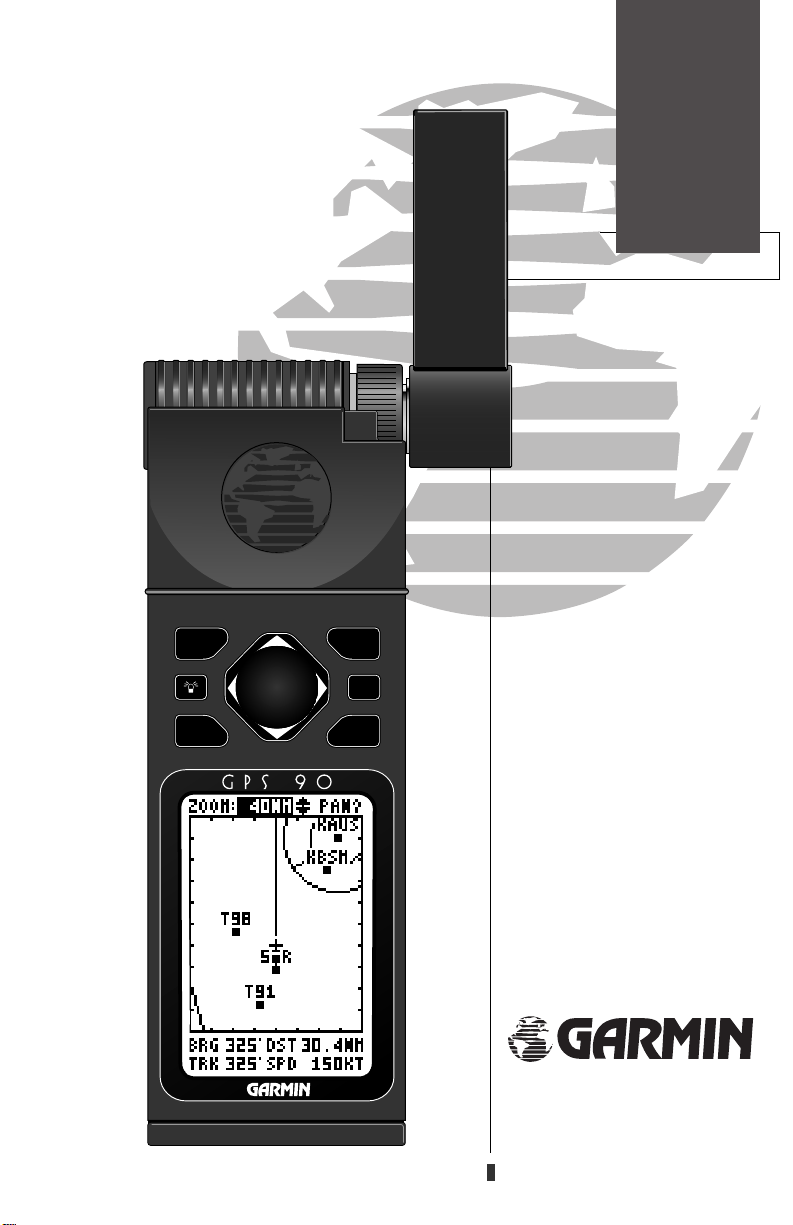
GPS90
Personal
TM
Navigator
®
Page 2

Page 3

Introduction
GPS 90
TM
Foreword
Personal Navigator
OWNER’S MANUAL
Software version 2.0 or above.
® 1995 GARMIN International
9875 Widmer Road, Lenexa, KS 66215, USA
GARMIN/Europe Ltd, Robert House, Station Approach
Romsey, Hampshire SO51 8 DU UK
All rights reserved. No part of this manual may be reproduced or transmitted
in any form or by any means, electronic or manual, including photocopying
and re c o rding, for any purpose, without the express written permission of
GARMIN.
I n f o rmation in this document is subject to change without notice. GARMIN
reserves the right to change or improve their products and to make changes in
the content without obligation to notify any person or organization of such
changes or improvements.
Part #190-00084-00 Revision A
March 1995 Printed in Taiwan
GARMIN, GPS 90, Personal Navigator, AutoLocate, MultiTrac-8 and
Spell’N’Find are trademarks of GARMIN International, and may not be used
without the expressed written permission of GARMIN International.
i
Page 4

Introduction
Cautions
CAUTION
The GPS system is operated by the United States Government, which is solely
responsible for its accuracy and maintenance. The system is subject to changes which
could affect the accuracy and performance of all GPS equipment. Although the GPS
90 is a precision device, any NAVAID can be misused or misinterpreted, and therefore
become unsafe.
Use the GPS 90 at your own risk. To reduce the risk of unsafe operation, carefully
review and understand all aspects of this Owner’s Manual and thoroughly practice
operation using the simulator mode prior to actual use. When in actual use, carefully
compare indications from the GPS 90 to all available navigation sources, including
other NAVAIDs, visual sightings, sectional charts, etc. Always resolve any discrepancies before continuing navigation.
N O T E : This device complies with Part 15 of the FCC limits for Class B digital
de vices. This equi pment gener ates, uses and can radiate radio frequency
energy, and if not installed and used in in accordance with the instructions, may cause
harmful interference to radio communications. However, there is no guarantee that
interference will not occur in a particular installation. If this equipment does cause
harmful interference to other equipment, which can be determined by turning the
equipment off and on, the user is encouraged to try and correct the interference by
relocating the equipment or connecting the equipment to a different circuit than the
affected equipment. Consult an authorized dealer or other qualified avionics service
technician for additional help if these remedies do not correct the problem. Operation
is subject to the following conditions: (1) This device may not cause harmful interference, and (2) this device must accept any interference received, including interference
that may cause undesired operation.
The GARMIN GPS 90 does not contain any user-serviceable parts. Repairs should
only be made by an authorized GARMIN service center. Unauthorized repairs or modifications could void your warranty and your authority to operate this device under
Part 15 regulations.
ii
Page 5

Introduction
Preface
Preface
Welcome to the smallest, easiest-to-use GPS navigator in the skies! The
G A R M I N GPS 90 re p resents GARMIN’s continuing commitment to pro v i d e
aviators with quality navigation information in a versatile, accurate and userfriendly design you’ll enjoy for years to come.
To get the most out of your new GPS, it’s important that you take the time
to read through the owner’s manual to understand the operating features of
the GPS 90. The manual is organized into two sections for your convenience:
The GPS 90 Ta k e o ff To u r is designed to familiarize you with the basic
operation of the unit through a simulated flight, where you’ll learn how to
t u rn the unit on and off, use the airport and waypoint database, select and
navigate to a destination, and use the moving map page in flight. The tour is
the fastest way to get the feel of your new GPS.
The R e f e rence Section p rovides detailed information and instructions to
the advanced features of the GPS 90 in a topical format. This allows you to
concentrate on a specific topic quickly, without reading through entire sections of text that you may not need.
Thanks for choosing the GARMIN GPS 90. We hope it will help you get the
most out of your aviation adventures. If you have any questions or comments
concerning the operation of the GPS 90, please contact our Product Support
staff at 913-599-1515 or 913-599-2103 (FAX).
iii
Page 6

Introduction
Capabilities
GPS 90 Capabilities
Designed for easy operation, the GARMIN GPS 90 offers powerful features
that help make aviation navigation come alive in the palm of your hand.
Precision Performance
• MultiTrac-8TMreceiver tracks and uses up to 8 satellites simultaneously for
fast, accurate positioning
• Differential-Ready for accuracy to 5 meters with optional beacon receiver
• Waterproof, dry nitrogen filled case and backlit LCD display
• Up to 20 hours of battery life on 4 AA batteries in battery saver mode
Advanced Navigating and Plotting
• Large, moving map display with Auto Zoom and SUA boundaries
• Internal Jeppesen®database includes detailed airport information, including runway length, surface and lighting, airport position and elevation,
communication frequencies and fuel services. Valuable information about
VORs, NDBs and Intersections is also available. See page 17 for basic
database coverage.
• 250 user waypoints with alphanumeric names up to six characters long
• 20 routes with up to 29 legs each
• One-touch GOTO navigation
• List of nine nearest airports, SUAs, VORs, NDBs, INTs or user waypoints
iv
Page 7

Introduction
Packing List
Before getting started with your new GPS, check to see that your GPS 90
package includes the following items. If you are missing any parts, please see
your dealer immediately.
Standard Package:
• GPS 90 Receiver
• Carrying Case and Wrist Strap
• Universal Yoke Mount Bracket
• Suction Cup Antenna Mount & Cable
• DC Power Cable
• 4 AA Batteries
• GPS 90 Owner’s Manual
• Quick Reference Card
• Warranty Card
• Country Airport Prefix Chart
Optional Accessories:
• PC Kit
• Serial Data Cable
• Cigarette Lighter Adapter
See your local dealer for optional accessories.
v
Page 8

Page 9

Table
Contents
Table of Contents
SECTION ONE Takeoff Tour
GPS Overview .............................................................................................................2
Basic Definitions..........................................................................................................3
Keypad Usage..............................................................................................................4
GPS 90 Takeoff Tour..............................................................................................5-15
SECTION TWO Reference
Waypoints & Database.........................................................................................17-26
Route & GOTO Navigation..................................................................................27-33
Status Page...........................................................................................................34-35
Position Page .............................................................................................................36
Moving Map Plotting............................................................................................37-41
Main Menu Page........................................................................................................42
Setup Menu..........................................................................................................43-50
Map Configuration Menu ..........................................................................................51
Alarms/CDI Menu................................................................................................52-54
E6-B Menu...........................................................................................................55-59
User Waypoints List & Messages...............................................................................60
Simulator .............................................................................................................61-62
Appendix A—Initialization........................................................................................63
Appendix B—Installation.....................................................................................64-65
Appendix C—Batteries & Electrical Wiring .........................................................66-67
Appendix D—Troubleshooting............................................................................68-71
Appendix E—Glossary.........................................................................................72-73
Appendix F—Messages ........................................................................................74-76
Appendix G—Time Offsets .......................................................................................77
Appendix H—Map Datums..................................................................................78-79
Appendix I—Index ..............................................................................................81-82
of
1
Page 10

Introduction
GPS Overview
What is GPS?
GPS (Global Positioning System) is a satellite-based navigation system developed
by the U. S. Department of Defense to provide a consistent, accurate method of
simplifying navigation. Originally designed for military applications, it also provides commercial and recreational users with 24-hour, worldwide navigation coverage with accuracy to 15 meters (49 feet).
How Does GPS Work?
GPS navigation uses satellite ranging to determine your position in relation to a
set of satellites orbiting the earth. The GPS constellation is made up of 24 satellites,
which continuously send radio signals containing precise position and time information for each satellite back to earth.
By knowing the position of any 3 or 4 of these satellites and calculating various
time differences between the transmitted signals, your GPS receiver can determine
its present position anywhere on earth. And once you’re under way, your GPS continuously updates your position and provides speed and track information.
What are the Advantages of GPS Navigation?
The GPS system provides pilots with a highly efficient, reliable system for pointto-point navigation without total reliance on traditional ground-based navigation
aids. GPS takes navigation to a higher level by providing accurate position and
course information, anywhere in the world, regardless of the weather or your proximity to traditional navaids. The accuracy and coverage of GPS navigation can help
make your flying safer, smarter and more efficient wherever you may travel.
2
Page 11

Getting
Started
Basic
Definitions
The GPS 90 is a powerful navigation tool that can guide you anywhere in
the world. To better understand its operation and capabilities, it may be helpful to review the basic terms and concepts briefly explained below.
Navigation is the process of traveling from one place to another and knowing
where you are in relation to your desired course.
Position is an exact, unique location based on a geographic coordinate system.
Most aviation navigation is based on the latitude/longitude coordinate system.
Meridians of longitude are a set of imaginary circles around the earth that pass
through the north and south poles. Longitude describes position in terms of how
many degrees it is east or west of the Prime Meridian (0º longitude).
Parallels of latitude are another set of imaginary circles that are perpendicular
to the earth’s polar axis. Latitude describes position in terms of how many
degrees it is north or south of the equator (0º latitude).
A waypoint marks an exact position fix so it can be recalled for future use. The
GPS 90 lets you mark waypoints electronically, without physical landmarks.
Bearing is a compass direction to a particular destination (waypoint) from your
present position.
Track is a compass direction representing your course over ground.
3
Page 12

Getting
Started
Keypad Usage
The GPS 90’s two-speed thumbkey allows convenient, one-handed entry of
information. Press on a particular arrow key once to scroll through data
options slowly, press and hold an arrow key for faster scrolling.
U D
L R
G
B
Q
P
M
E
• Use the up and down arrow keys to select alphanumerical characters and
menu choices and to move the field highlight from field to field.
• Use the left and right arrow keys to move the selected character field and
to move the field highlight from field to field.
The GOTO/NRST key quickly sets a direct course to a selected destination.
Pressing GOTO twice activates the NRST mode.
The POWER key turns the unit on and off and activates screen backlighting.
To turn the unit off, press and hold the POWER key for 3 seconds.
The QUIT key returns you to a previous page, or clears data entry, restoring
a data field’s previous value.
The PAGE key scrolls through main data pages in sequence and returns the
display from a submenu page to the previous page viewed. It also displays
the message screen when a message alert appears.
The WPT key provides access to the GPS 90’s internal database of airports,
VORs and other waypoints and the AutoStore function.
The ENTER key confirms data entry and on-screen responses. The ENTER
key also activates highlighted fields to allow data entry.
4
Page 13

The GARMIN GPS 90 is a powerful navigation tool that
o ffers pilots a host of advanced features that help make
flying safer and more efficient. The Ta k e o ff Tour is
designed to quickly guide you through basic features and
functions of the GPS 90 using a simulated trip.
Once you’ve completed the tour and become familiar
with the main pages and features of the unit, refer to the
reference section for complete instructions on installation,
initialization and performing specific tasks and functions.
The takeoff tour assumes you have not changed any of
the default settings for the unit. If you have changed any
settings, the descriptions and pictures used may not
match your configuration (see the troubleshooting sec
tion in Appendix D to reset your unit to default settings).
Yo u ’ re now ready to power up and take off with
GARMIN GPS!
1. Press and hold the Bkey until the Welcome page appears.
Takeoff
Tour
Power On
2. After the unit performs a self-test, the Database Information
page will appear, listing the issue date of the internal aviation
database.
After a few seconds, the Database Information page will
be replaced with the Satellite Status page. The Status page
provides a visual reference of satellite acquisition and status, with signal strength bars and a satellite sky view in
the center of the screen. The battery level gauge provides
an indication of how much battery life you have left in
the internal batteries, and will only appear when you are
not connected to external power.
By now, you should also have an on-screen message
box flashing on the screen. To view the message:
1. Press the Pkey.
The ‘Searching the Sky’ message informs you that the
GPS 90 has not yet been initialized to a GPS position.
Since our tour will use the simulator mode, we don’t need
to worry about acquiring satellites just yet.
Status Page
IMPORTANT!
If you’re already
familiar with GPS
navigation and
would like to skip the
Takeoff Tour, please
refer to page 63 for
instructions and tips
on initializing your
unit for first time use.
Once the unit has
been properly initialized, you should
acquire satellites
and obtain a position
within a few minutes
each time you power
the unit up.
5
Page 14

Takeoff
Tour
Page Sequence
& Simulator
Status Page Position Page Map Page Nav Page Main Menu
Use the Page and Quit keys to continuously scroll through the main pages in either direction.
To exit the Message page and return to the previous
page:
1. Press the Pkey.
The GPS 90 features five main pages in a continuous
loop: Satellite Status, Position, Map, Navigation and
Main Menu. Try scrolling through the pages by pressing
the P key. You can also scroll the opposite direction
(or return to a previous page) by pressing the Qkey.
Select the ‘Simulator’
option from the current mode field.
6
To continue the Takeoff Tour, you’ll need to put the
GPS 90 in simulator mode:
1. Press Prepeatedly until the Main Menu page appears.
2. Use Uor Darrow key to move the field highlight to the
‘Setup Menu’ option.
3. Press the Ekey.
4. The setup menu will appear, with the ‘Operation Mode’
option highlighted. Press the Ekey.
5. Once the Operation Mode page appears, use the Dkey
to highlight the ‘Current Mode’ field.
6. Press Eto begin selection of the operating mode.
7. Use the Uand Dkeys to toggle through and select the
‘Simulator’ option.
8. Press Eto confirm the simulator selection.
Page 15
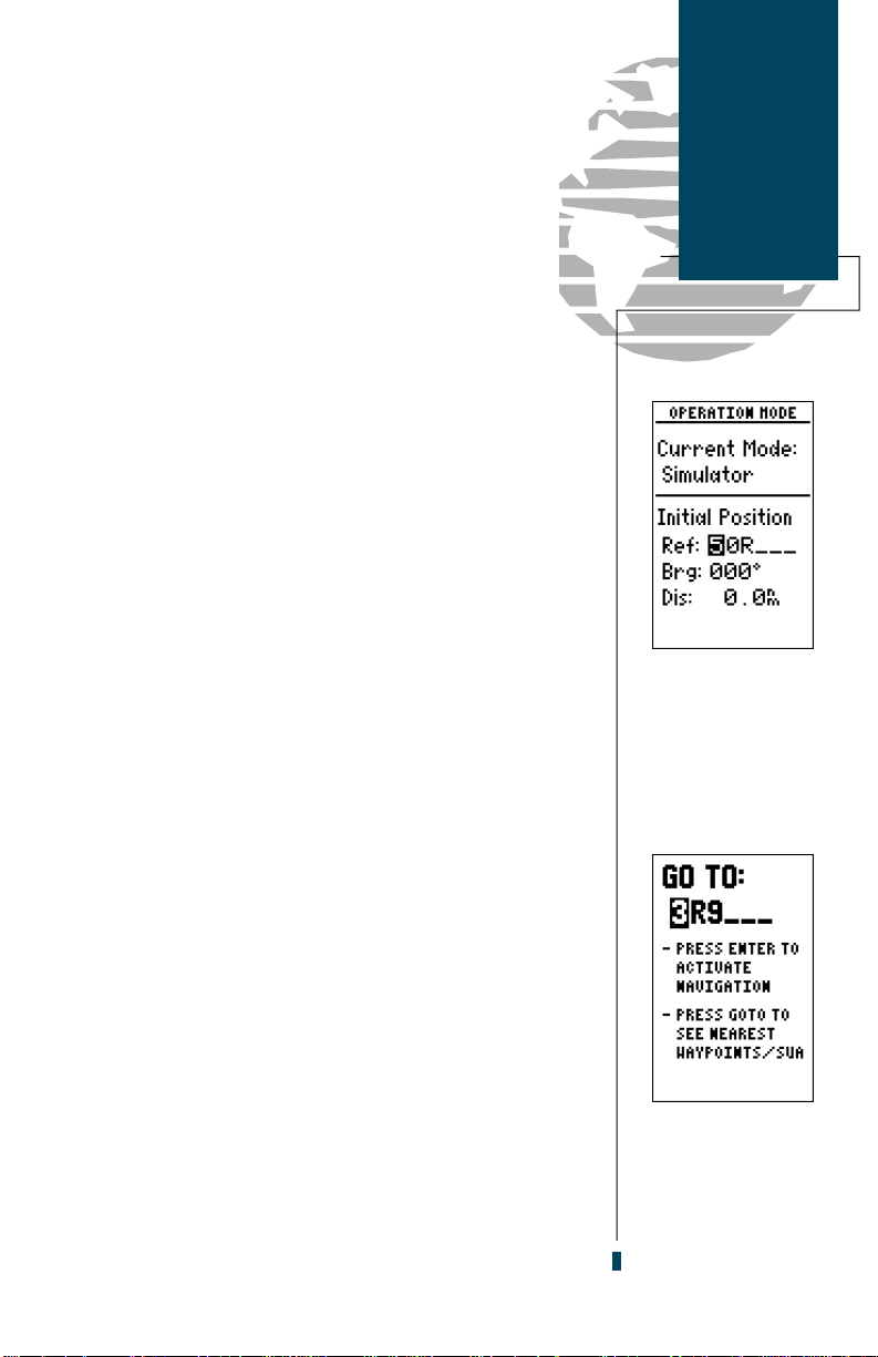
The field highlight will move to the Initial Position
field, where we can now enter the starting position of
our flight, Lockhart Municipal Airport (50R, the ICAO
identifier), in Lockhart, Texas:
1. Press Eto begin initial position entry.
2. Use theDkey to scroll through and select ‘5’,
the first number of the identifier.
3. Press the Rkey to move the field highlight to the next
character position.
4. Repeat steps 2 and 3 until you have spelled out ‘50R’ in the
waypoint identifier field.
5. Press Eto confirm your selection.
Since we’ll be taking off from the airport, keep the
position and bearing values at zero to keep our position
right on the airport. To return to the Main Menu Page:
1. Press the Qkey twice.
Once you have entered the starting position of your
flight, the next step is to select our GOTO destination,
Lakeway Airport (3R9) in Austin, Texas:
Takeoff
Tour
Going to a
Waypoint
Entering an initial
position from the
operation mode
setup page.
1. Press the Gkey.
2. The GOTO Page will appear with the waypoint identifier
field ready to accept changes.
3. Use theUand Dkeypad to enter the identifier of the
destination waypoint (3R9).
4. Press the Ekey to confirm your destination.
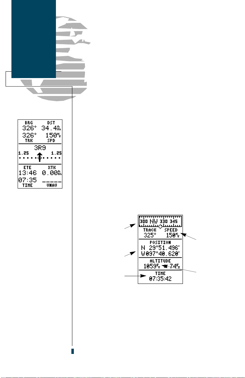
Once a GOTO is activated, the Navigation Page will
display the bearing (BRG) and distance (DST) to the
destination, along with your present speed (SPD) and
track over ground (TRK). The GOTO destination is listed above the course deviation indicator, with your estimated time enroute (ETE), cross track error (XTK) and
time displayed at the bottom of the page. A re l a t i v e
bearing pointer, located above the CDI scale, points to
the direction of your destination.
Confirm the GOTO
destination by pressing the ENTER key.
7
Page 16
Takeoff
Tour
Navigation &
Position Pages
Now we’ll need to enter a speed for the aircraft:
1. Use the arrow keypad to highlight to the ‘SPD’ field.
2. Press the Ekey to begin ground speed entry.
3. Use the arrow keypad to enter a speed of 150 knots.
4. Press Eto confirm the speed entry.
Once a speed has been entered, the Nav page will continuously update as we make our way to the destination
airport. We now need to enter the cruising altitude of our
flight, which can be entered from the Position page:
1. Press the Pkey until the Position page appears.
2. Press theUkey to move the field highlight to the altitude
field and press E.
3. Use the arrow keypad to enter an altitude of 2,500 feet (leave
the first altitude digit at zero, or you’ll be at 25,000 feet).
The Navigation page
displays your present
speed and course over
the ground, along
with the distance and
bearing to your destination. The CDI scale
and relative bearing
indicator help keep
you on course, while
your ETE and cross
track error are shown
at the bottom of the
Nav page.
8
4. Press Eto confirm the altitude.
Graphic heading
indicator
Present position
Time of day
(local or Zulu)
Present speed
over ground
Current GPS
altitude
The GPS 90 Position page displays your present latitude, longitude and altitude, along with your curre n t
track and speed over the ground. The top of the page also
features a graphic heading indicator, which displays your
cardinal heading as you’re moving. The time of day, displayed in UTC or local time, is indicated at the bottom of
the page. To enter a local time offset, see page 46.
Page 17
Most of your in-flight navigation with the GPS 90 will
center around the Navigation and Moving Map pages.
Now that we’re on our way, let’s move on to the Map page:
1. Press the Pkey.
The GPS 90’s Moving Map page provides extensive
capabilities and information on your present position,
nearby facilities and waypoints, special use airspace and
your active route. Before we go through a few of the basic
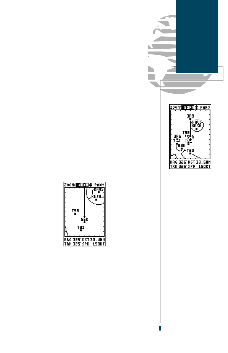
features, let’s zoom in for a closer look at our progress:
1. Verify that the map scale field, located at the top of the page,
is highlighted. If it isn’t highlighted, press theUkey repeatedly until it is highlighted.
2. Press the Ekey.
3. Press theDkey once to change the scale to the 40nm
setting, and Eto return the cursor to the default position.
Once you’ve zoomed in to the 40 nm scale, you’ll be
able to see a clear presentation of your plane, nearby airp o rts and the speci al use airspace around Mue ller
Municipal Airport (KAUS). The line between 50R and 3R9
re p resents the track-up route from our starting point to
the destination airport, with your present position indicated by the plane icon. Notice that the plane icon remains
centered on the map, while nearby airports and airspace
move by relative to your present speed and track.
Takeoff
Tour
Moving
Map Page
The Map page shows
your present position
as a plane icon in
track up mode, with
nearby airports and
special use airspace
boundaries indicated
right on the map.
To reduce map clutter
at higher scales, you
can turn off the waypoint identifiers (and
other features) from
the map configuration
setup described on
page 51.
9
Page 18

Takeoff
Tour
Moving Map
Basics
Selecting an onscreen waypoint.
Zoom and pan-
ning controls
Moving
map field
(8 x 10 grid)
Speed, distance &
angle fields
The Moving Map page can be broken down into three
parts: the zoom and pan fields, located at the top of the
page; the moving map field; and speed distance and
angle fields, located at the bottom of the page. The
zoom and pan fields provide access to the map scale and
scrolling cursor functions, while the map field lets you
highlight on-screen airports and waypoints for immediate review. The speed, distance and angle fields are display fields only, and do not provide access to other functions.
The default placement of the cursor highlight is on
the zoom field. To move the cursor to the pan field or
through the on-screen waypoints, simply use the arrow
keypad to move in the desired direction, and press
E
to activate the function or review the selected waypoint.
Try selecting KAUS, located just to the right of your
current route, to practice:
Review any highlighted waypoint by pressing the ENTER key.
10
1. With the field cursor on the zoom field, press the Dkey
repeatedly until the KAUS identifier is highlighted.
2. Press the Ekey to review the waypoint page for KAUS.
The waypoint location page for KAUS will appear,
p roviding you with the facility’s name and location
(city/state/region), with the elevation, latitude and longitude of the field indicated on the bottom half of the
page. The fuel available (AV, jet or MOGAS) at the
facility is also displayed.
Page 19
Available
frequencies
Airport page prompts
Identifier
field
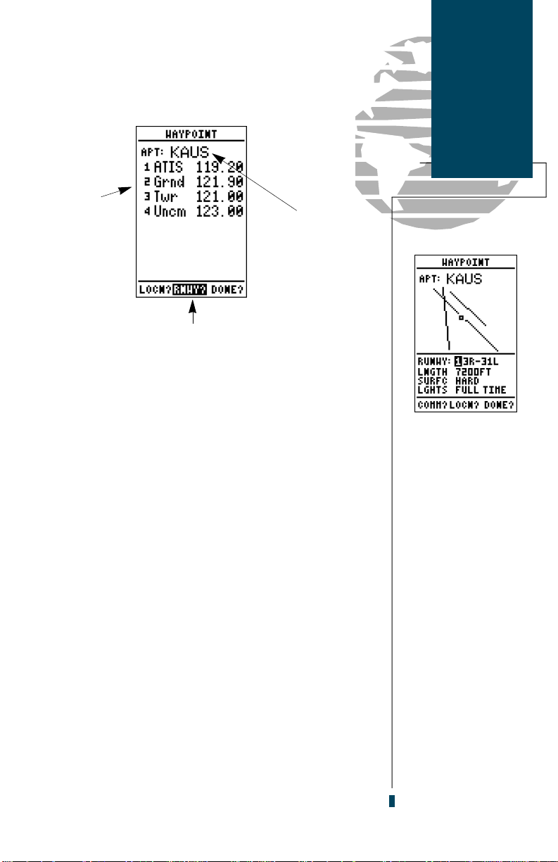
In addition to the location page, each airport in the
GPS 90’s database feature separate communication and
runway pages, which are accessible from the pro m p t s
located in the bottom field of any airport page.
To view the Airport Communication page:
1. Press L to move the field highlight to the ‘COMM’ prompt.
2. Press E.
All of the available frequencies for the selected airport
will be displayed, with the designation indicated at the
left of each frequency. If there are more than 8 frequencies for a selected airport, use the down arrow key to
view additional frequencies.
Once you have moved from the initial page of an airp o rt re v i e w, the prompt highlight will automatically
move forward to the next available prompt. This allows
you to continuously scroll through airport inform a t i o n
pages by simply pressing the Ekey repeatedly.
To view the runway information page:
Takeoff
Tour
Airport Pages
The airport runway
page shows a NorthUp display of all
available runways,
with the designation,
length, surface and
lighting conditions
available for each
runway.
To view additional
runways, highlight
the ‘RUNWY’ field
and press ENTER,
then use the arrow
keypad to toggle
between the various
runways.
1. Press E.
11
Page 20

Takeoff
Tour
Special Use
Airspace
The GPS 90’s sectorized SUA boundaries
let you watch your
proximity right on
the moving map.
The runway information page features a diagram of
available runways, along with runway length, surf a c e
type and lighting for each ru n w a y. To re t u r n to the
Moving Map page:
1. Move the field highlight to the ‘DONE?’ prompt.
2. Press E.
Once you’re back on the Moving Map Page, you’ll
notice that our plane is getting close to the special use
airspace surrounding KAUS. Whenever you are within 2
nm of an SUA, projected to enter an SUA or inside an
SUA, the GPS 90 will notify you with a message and
supply detailed information on each SUA you are being
alerted to. By looking closely at the map display, you’ll
notice that we will come very close to the KAUS SUA,
but not actually enter it. Once our flight takes us within
2 nm of the SUA, we’ll be alerted with a ‘Near SUA
< 2nm’ message (you may have to wait a minute or so to
get the message, depending on how fast you’ve made
your way through the Takeoff Tour).
To view the SUA message:
1. Press the Pkey.
The nearest SUA
page provides information about special
use airspaces you are
being alerted to.
12
2. To return to the Map page, press Pagain.
Additional information, including the name, class,
c o n t rolling agency and altitudes, is available from the
key. To view additional SUA information:
G
1. Press the Gkey twice. The nearest SUA alarm page will
appear, listing up to 9 SUA warnings you are being alerted
to. Each listing will display the type of warning and your ETE
to intrusion, if applicable.
2. To view specific information on any listed SUA, highlight the
desired SUA name and press E. The SUA page will
appear, providing additional information on floor and
ceiling altitudes for the selected SUA.
3. To return to the Nearest SUA list, press the Ekey.
4. To return to the Map Page from the SUA list, press Q.
Page 21
SUA alert messages for class B, class C, MOAs,
restricted and other areas may be turned off to avoid
nuisance alerts, and may also be removed from the map
to avoid excess clutter at higher map scales. For complete information and definitions on SUAs, see page 52.
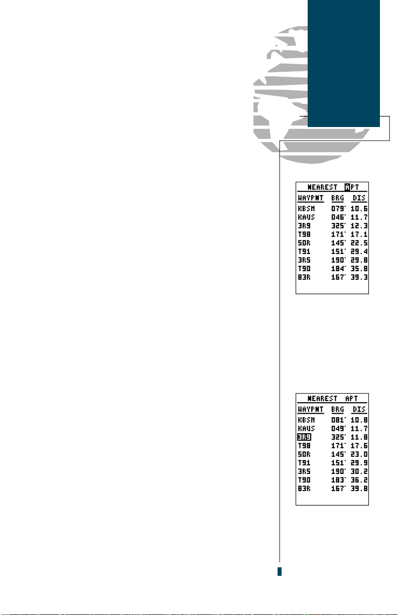
The GPS 90’s nearest function will also provide you
with a list of the nine nearest airports, VORs, NDBs,
intersections and user waypoints to your present position. The internal Jeppesen database used in the GPS 90
contains information about thousands of waypoints,
which are divided into specific categories for your convenience. For more on waypoint categories and the
internal database, please see page 17-27 after completing
the takeoff tour.
To view the nearest waypoints of a particular category
(airports, VORs, NDBs, intersections or user waypoints),
you need to select the desired category from the category
field at the top of the nearest page. Let’s practice by
viewing the nearest airports to our present position:
1. Press the Gkey twice to display the nearest page.
2. Press Eto begin selection of the desired category.
3. Press theDkey repeatedly to scroll through the waypoint
categories until ‘APT’ appears in the category field.
Takeoff
Tour
Nearest
Waypoints
The GPS 90 displays
the nine nearest airports, VORs, NDBs,
intersections or user
waypoints to your
present position.
4. Press Eto confirm the category. The field highlight will
move to the first facility on the list.
Once you’ve selected and confirmed a category, the
GPS 90 will display the nine nearest facilities and provide the distance and bearing to each waypoint in the
list. To scroll and review the nearest waypoints list:
1. Press theDkey to highlight to the desired waypoint.
2. Press Eto review the waypoint page(s).
3. Press Eagain to return to the nearest list. The field
highlight will sequence to the next waypoint on the list.
4. Press Qto exit the nearest function and return to the
previously viewed page.
To review a nearest
waypoint, highlight
the identifier and
press ENTER.
13
Page 22
Takeoff
Tour
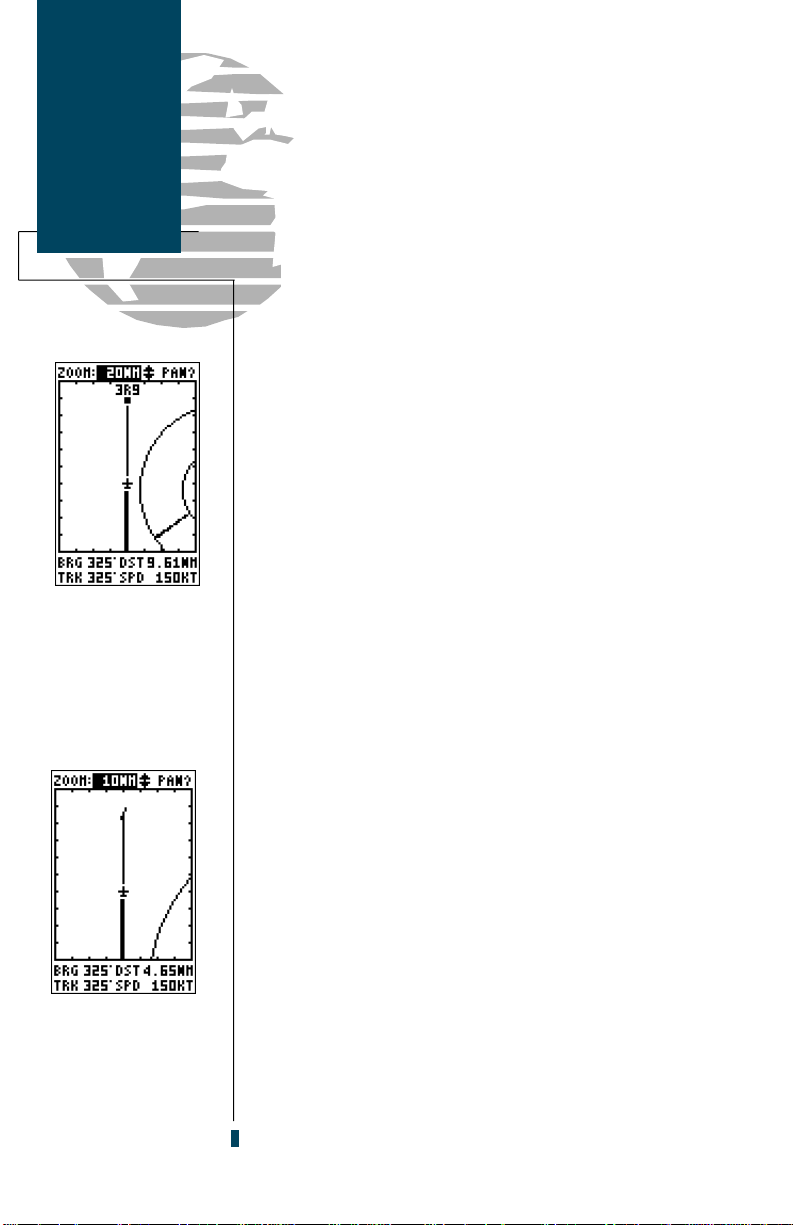
AutoZoom
AutoZoom at 20 nm
map scale.
Now let’s return to the Map page to finish the tour. If
you’re not already on the Map page:
1. Press Prepeatedly until the Map page appears.
You may have noticed that a s we make our way
towards the destination airport, the map scale has automatically zoomed in to provide a closer look of the airp o r t. What you’re actu all y s ee ing is the GPS 90’s
AutoZoom feature. Whenever you select a GOTO destination, the Map Page will default to the 80 nm setting, and
gradually zoom down the map scale to the 1 nm setting.
The map scale will zoom to the next lowest setting
(i.e., from 80 nm to 40 nm) whenever the map can fit
both your present position and your destination on the
screen. If you manually zoom in the map scale before this
point, the AutoZoom feature will resume once it catches
up to the map scale you have selected (down to
2 nm). If the map is manually zoomed out beyond the
AutoZoom scale, the Autozoom will be cancelled, and the
GPS 90 will assume you want to stay at the scale you
have manually selected. For more information on the
AutoZoom feature, please see page 41.
By now, our plane should be approaching 3R9, the destination airport. As the map zooms in to the 10 nm range,
you’ll be able to see the runway appear right on the
screen. Let’s move back to the Navigation page and finish
up our tour:
AutoZoom at 10 nm
map scale.
14
1. Press the Pkey to display the Navigation Page.
As we fly past the airport, notice that the GPS 90 continues to provide navigation to 3R9, with the re l a t i v e
bearing pointer and ETE fields indicating we are past our
destination. The GOTO destination may be cancelled by
activating another GOTO or cancelling the current GOTO
destination. To cancel the current GOTO:
1. Press the Gkey.
2. Press Lonce to clear the destination field (pressing
clears a selected field)
3. Press Eto confirm the cancellation.
L
Page 23

Congratulations! You’ve now mastered some of the
basic features of the GPS 90, and are ready to take to the
skies with a powerful tool that can help make all your
flights a little smoother and a lot more efficient. Be sure
to carefully review the sections on initialization, installation and the internal database so you can get the most
out of your new GPS. The rest of the manual is organized
as a topical reference, so you may quickly find instructions and explanations on the GPS 90’s powerful features.
To turn the GPS 90 off:
1. Press and hold the Bkey for 3 seconds.
Thank you for choosing the GARMIN GPS 90. We
hope that it will be a valuable navigation tool for you,
wherever your course may take you.
Takeoff
Tour
Power Off
The power off countdown he lp s pr e v e n t
the GPS 90 from being
powered down accidentally.
15
Page 24

16
Page 25

The GPS 90 uses an internal Jeppesen®database to
provide position and facility information for thousands of
airports, VORs, NDBs and intersections. Each facility in
the database is stored as a waypoint, with its own latitude/longitude, identifier (up to six letters and/or numbers) and other pertinent information. Up to 250 user
waypoints may also be created and stored in memory.
Waypoint information is available through the GPS 90’s
WPT key. Waypoints are divided into five categories for
your convenience. Each category provides different types
of detailed information for a selected facility:
• A i r p o rt s — I d e n t i f i e r, city/state, country, facility
name, position (lat/lon), elevation, fuel serv i c e s ,
runways, and communications frequencies.
• VORs— Identifier, city/state, country, facility name,
position (lat/lon), frequency and co-located DME or
TACAN availability.
• NDBs— Identifier, city/state, country, facility name,
position (lat/lon) and frequency.
• I n t e r s e c t i o n s — I d e n t i fie r, re g i o n / c o u n t ry, position
(lat/lon) and range/bearing to nearest VOR.
• U s e r — Identifier (name), position (lat/lon), user
comments and reference waypoint.
To view the waypoint information for a desired waypoint, select the waypoint category from the category
field, located at the top left of the waypoint page, next to
the identifier field.
To choose a waypoint category:
1. Press Mto display the waypoint page.
2. Use the arrow keypad to highlight the category field.
3. Press Eto begin selection of the waypoint category.
Waypoints
& Database
Waypoint
Categories
The GPS 90’s internal
Jeppesen database
is available with an
Americas (North,
Central & S. America)
or International database (Europe, Africa,
Asia, Australia &
Greenland). Hawaii is
included in both database versions.
The database cycle is
displayed on the
Database Information
page. Information on
updating the database
is included with your
GPS 90 package.
4. Use the Uor Dkeys to select the desired category.
5. Press Eto confirm the category selection.
17
Page 26

Waypoints
& Database
Viewing
Waypoint Data
Entering a waypoint
identifier.
After a waypoint category is selected, information for a
waypoint can be viewed by entering the identifier or
name of the desired waypoint. Airports, VORs, and NDBs
may be entered by either the identifier, name, or the location (city) of the facility. Intersections and user waypoints
must be entered by the identifier.
To enter a waypoint identifier:
1. Use the arrow keypad to highlight the identifier field.
2. Press E.
3. Use the Uand Dkeys to spell out the desired identifier,
using the Rkey to move to the next character position.
As the identifier is entered, the GPS 90’s Spell’N’Find
feature will scroll through the available database, displaying any waypoints with the same identifier letters you
have entered to that point. When the desired waypoint is
displayed, press E.
Once you’ve selected a waypoint category, waypoint
information can also be retrieved by entering the facility
name of the airport, the name of the VOR or NDB, or
their city name (intersections and user waypoints cannot
be retrieved by facility or city name).
To select a waypoint by facility or city name:
Entering a waypoint
by facility name.
18
1. Select the desired waypoint category (APT, VOR or NDB).
2. Use the arrow keypad to highlight the facility name or city
name field.
3. Press Eto begin entry of the facility or city name.
4. Enter the name of the facility or city with the arrow keypad.
5. The GPS 90’s Spell’N Find feature will scroll through the
available database, displaying any waypoints with the same
letters you have entered to that point.
6. When the desired waypoint appears, press E.
Page 27
Once a waypoint category and identifier have been
selected, the GPS 90 will provide extensive information
t h rough various waypoint review pages. The following
waypoint information is available:
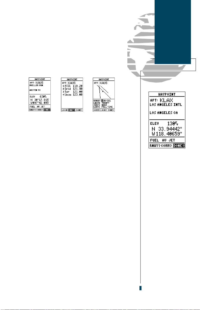
AIRPORT INFORMATION
The GPS 90 features three airport pages:
• Airport location— allows entry of desired airport
by identifier, facility name or city and displays latitude, longitude and elevation; and fuel availability.
• Airport communication— allows entry of desired
a i r p o rt by identifier and displays radio fre q u e n cies/usage.
• Airport runway— allows entry of desired airport
by identifier, displays runway designations, length,
surface and lighting information; and/or pilot controlled lighting frequencies.
To scroll through the airport pages:
1. Select the airport category and enter the desired airport
identifier. The airport page initially displayed will be the
same as the last airport page viewed.
2. Use the Lkey to move the field highlight to the desired
page prompt and press E.
Once you have moved from the initial airport page
displayed, the page prompt will automatically move forw a rd to the next available prompt. This allows you to
continuously cycle through the airport pages by simply
pressing the Ekey repeatedly.
To exit the airport pages and return to the previously
viewed page:
Waypoints
& Database
Airport
Information
The internal database
uses ICAO identifiers
for all airport names.
All U. S. airports which
contain only letters use
the prefix ‘K’. For
example, Los Angeles
International is KLAX
under the ICAO
standard.
Other airports, such as
Otten Memorial (3VS),
that contain numbers
in the identifier, do not
require the ‘K’ prefix.
Many countries outside
the U. S. use two letter
prefixes. For more
information, contact
the
International
Aviation Organization.
Civil
1. Press the Qkey.
19
Page 28

Waypoints
& Database
Location &
Comm Pages
In some instances, all
available frequencies
for a selected airport
may not fit on the
communication page.
To view additional
frequencies, use the
DOWN ARROW key
to scroll through and
view any additional
frequencies.
Facility Name
(selectable)
City/State
(selectable)
Available fuel types
Identifier field
(selectable)
Location field
The GPS 90’s airport location page displays the latitude,
longitude and elevation of the selected airport, as well as
fuel availability. From the airport location page, you can
enter a desired airport by identifier, facility name or city as
described on page 18. The following descriptions and
abbreviations are used on the airport position page:
Elev— Elevation in feet or meters.
Position— In the position format you have curre n t l y
selected from the setup page.
Fuel— Lists the types of fuel available on the airport:
• AV gas— 80-87 octane, 100 LL, 100-130 octane
• JET— Jet A, Jet A-1 or Jet A+
• MOGAS— 87 octane unleaded
The airport communication page (shown in the left
margin) displays radio frequencies and their usage for the
selected airport, and allows entry of a desired airport by
identifier only (see page 18). The following fre q u e n c i e s
are displayed if available:
• ATIS— Automatic terminal information service
• Grnd— Ground
• Twr— Tower
• Uncm— Unicom/Multicom
20
Page 29

The last airport page is the runway page, which features a diagram of available runways, along with designations, length, surface and lighting information for the
selected airport.
Identifier field
Runway
Diagrams
(selectable)
Waypoints
& Database
Airport
Runway Page
Runway
Designator Field
(selectable)
Runway Data
The runway diagram provides a north-up graphic of
available runways, with length, surface and lighting data
listed below the runway designation. The ‘SURFC’ field
will display one of the following surface types: hard ,
t u rf, sealed, gravel, dirt, soft, unknown or water. The
‘LGHTS’ field will indicate one of five lighting schemes:
part time, full time, pilot controlled (with frequency), no
lighting or unknown.
If a selected airport has more than one runway, additional runways can be viewed by selecting another runway from the designation field.
To view additional runways:
1. Highlight the runway designation field.
2. Press the Ekey.
3. Use the arrow keypad to toggle through and select the
desired runway.
4. Press Eto return the cursor to the ‘DONE?’ prompt.
Additional runways
are accessed through
the runway designator field
Pilot controlled
lighting with
frequency listed.
21
Page 30

Waypoint
& Database
Intersections
and NDBs
GPS 90 intersection
waypoint page.
INTERSECTION INFORMATION
The GPS 90’s intersection waypoint page allows entry
of a desired intersection by identifier and displays position and nearest VOR data for a selected intersection.
To view waypoint information on an intersection:
1. Select the intersection category from any waypoint field.
2. Enter the identifier of the desired intersection and press
the Ekey.
The GPS 90 will display the intersection’s latitude and
longitude below the identifier field, and calculate the
bearing and distance to the nearest VOR facility. Note that
the VOR displayed may not necessarily be the facility
used to define the intersection. The region and country of
the intersection will also be displayed at the bottom of the
page to help you confirm the location in the event of
duplicate identifiers.
NDB waypoint page.
22
NDB INFORMATION
The next waypoint category in the GPS 90’s intern a l
database is NDB facilities. The NDB waypoint page allows
you to select a desired NDB by entering the identifier,
facility name or city (see page 18). In addition to displaying the identifier, facility name and city/state of the NDB,
the NDB page will show the latitude and longitude of the
facility, the region/country, & the transmitting frequency.
To view waypoint information on a NDB:
1. Select the NDB category from any waypoint category field.
2. Enter the identifier, facility name (on the second line) or city
(on the third line) of the desired NDB.
3. Press the Ekey.
Page 31

VOR INFORMATION
The GPS 90’s VOR waypoint page allows you to enter
a desired VOR by identifier, facility name, or city name
and displays the selected facility’s position, fre q u e n c y
and other information.
To view waypoint information for a VOR:
1. Select the VOR category from any waypoint category field.
2. Enter the identifier, facility name or city of the desired VOR.
3. Press the Ekey.
The VOR page lists the identifier, facility name and
city/state of at the top of the page, with the transmitting
frequency of the facility listed below. If DME or TACAN
equipment is co-located at the site, it will be indicated
next to the transmitting frequency of the VOR. The latitude and longitude is also displayed, with the region and
country indicated at the bottom of the page.
Waypoints
& Database
VORs and
User Waypoints
VOR waypoint page.
USER WAYPOINT INFORMATION
The last waypoint category available from the GPS 90’s
WPT key is user waypoints. The user waypoint page
allows entry of a desired waypoint by name/identifier
and displays the waypoint’s position, user comments and
a reference waypoint field to calculate the distance and
bearing to any other waypoint in the database. The user
waypoint page can also be used to create up to 250 waypoints by manually entering a position or defining a
range and bearing from an existing waypoint.
To view waypoint information for a user waypoint:
1. Select the USR category from any waypoint category field.
2. Enter the identifier/name of the desired user waypoint.
3. Press the Ekey.
User Waypoint page.
23
Page 32

Waypoints
& Database
Creating User
Waypoints
Entering a new user
waypoint’s name.
The user waypoint page allows you to create new way-
points three ways:
• Enter the exact position of the new waypoint
• Reference a waypoint already in the database
• Enter a range and bearing from your present position
To first step in creating a new waypoint (regardless of
what method you’re using) is to assign a name/identifier
for the new waypoint.
To create a new waypoint from the user waypoint page:
1. Select the ‘USR’ category from any waypoint category field
and press E. The highlight will advance to the name field.
2. Press the Ekey to begin entry of your waypoint name.
3. Use the arrow keypad to enter the waypoint name.
4. Press Eto accept the waypoint name.
Once the name has been accepted, the field highlight
will move to the position field, where you can manually
enter the position of the new waypoint:
Entering a new user
waypoint’s position.
24
1. Press Eto begin entry of the waypoint position.
2. Use the arrow keypad to enter the lat/lon. The Land Rkeys
will advance the cursor to the desired character position.
3. After the latitude and longitude entry is complete, press
to save the new waypoint.
E
If you are defining the new waypoint position by referencing (entering a distance and bearing from) a known
waypoint or your present position:
1. Use theDkey to highlight the ‘REF’ field.
2. If you are referencing a waypoint, press Eand use the
arrow keypad to enter the identifier of the reference waypoint
(If you want to reference your present position, leave the
‘REF’ field blank).
3. Press the Ekey.
(continued on page 25)
Page 33

The field highlight will automatically advance to the
bearing field. To enter a bearing and range from the
reference position:
1. Press Eto begin entry of the compass bearing.
2. Use the arrow keypad to enter the bearing of the new waypoint from the reference position.
3. Press Eto confirm the bearing. The field highlight will
automatically move to the distance field.
4. Press Eto begin entry of the distance.
5. Use the arrow keypad to enter the distance of the new waypoint from the reference position.
6. Press Eto confirm the distance. The GPS 90 will calculate the coordinates of the waypoint and store it in memory.
Once a new user waypoint is saved, the GPS 90 will
assign a default user comment (the date and time of creation) to the new waypoint. You can change the default
comment to a custom comment at any time, right from
the user waypoint page.
To enter a user comment:
Waypoints
& Database
User
Waypoints
Entering a range and
bearing from a reference waypoint.
1. Use the arrow keypad to highlight the comment field.
2. Press the Ekey.
3. To clear the default comment, press the Lkey.
4. Use the arrow keypad to enter the comment. Press E.
The delete and rename prompts, located at the bottom
of the user waypoint page, allow you to quickly remove
a waypoint from memory or change the name of an
existing waypoint.
To delete a user waypoint:
1. Use the Lkey to move the field highlight from the ‘DONE’
prompt to the ‘DELETE’ prompt and press E.
2. Use the Lkey to highlight the ‘Yes’ prompt and press E.
Deleting a User
Waypoint
25
Page 34

Waypoints
& Database
User Waypoints
& AutoStore
The user waypoint page also allows you to rename any
user waypoint in memory.
To rename a user waypoint:
1. Use the arrow keypad to highlight the ‘RENAME’ prompt.
2. Press the Ekey. The rename waypoint page will appear.
3. Use the arrow keypad to enter the new waypoint name.
4. Press E. The highlight will advance to the ‘Yes’ prompt.
5. Press Eto accept the new name, or Qto cancel.
The WPT key is also used to save new waypoints using
the GPS 90’s AutoStoreTMfunction. AutoStore allows you
to quickly store your present position and add the new
waypoint to a selected route if desired.
To save your present position using AutoStore:
Renaming a user
waypoint.
Marking an
AutoStore position.
26
1. Press the Mkey twice to capture your position
(if you’re already on a waypoint page, you’ll only need to
press the Mkey once).
The AutoStore page will appear, showing the captured
position and a default 3-digit waypoint name. To change
the default position name :
1. Use the arrow keypad to highlight to the name field.
2. Press Eto begin entry of your waypoint name.
3. Use the arrow keypad to enter the name.
4. Press E. The field highlight will move to the ‘route’ field.
If you’d like to add the waypoint to a route:
1. Press the Ekey.
2. Enter the desired route number and press E.
3. Press the Ekey to confirm the route number.
To save the AutoStore waypoint:
1. Highlight the ‘save’ field and press E.
Page 35

One of the many benefits of GPS navigation is the
ability to fly directly to a waypoint or fly a chain of waypoints without relying totally on ground based navigation aids. To take advantage of the convenience and efficiency of point-to-point GPS navigation, the GPS 90
provides two methods of selecting a destination for your
flight: GOTO and route navigation. The GOTO function provides a fast way to set a course to a destination
f rom your present position, while the route function
allows you to create a chain of waypoints to fly in
sequence towards a selected destination.
Routes
Overview
Whether you’re flying a GOTO course or a ro u t e ,
there are a few basic concepts and terms that apply to all
point-to-point GPS navigation. Routes are broken down
and navigated in smaller segments called ‘legs’. The dia-
gram above shows a basic route consisting of five waypoints and four legs. The waypoint you are going to in a
leg is called the ‘active to’ waypoint (MAP), and the
waypoint immediately behind you is called the ‘ a c t i v e
f ro m ’ waypoint (SGF). The line between the ‘active to’
and the ‘active from’ waypoint is called the ‘active leg’.
When you activate a route with the GPS 90, it will
automatically select the route leg closest to your position
as the active leg, and provide navigation guidance directly to the ‘active to’ waypoint of that leg. As you pass a
waypoint in your route, the unit will select the next waypoint as the ‘active to’ waypoint.
27
Page 36

Routes
GOTO function
Selecting a GOTO
destination.
The GPS 90’s GOTO function lets you choose any
stored waypoint as a destination and quickly set a course
from your present position. Once a GOTO has been activated, the Navigation Page will provide you with steering
guidance to your destination.
To activate the GOTO function:
1. Press the Gkey.
2. The GOTO Page will appear with the waypoint field ready to
select a destination. Enter your destination waypoint.
3. Press the Ekey to confirm the waypoint.
You can also quickly activate the GOTO function from
any other page by simply highlighting a waypoint, pressing the Gkey and confirming the GOTO page.
Another time-saving feature of the GPS 90 that you
may have noticed when entering waypoint names is the
Spell’N’Find feature. As you enter waypoint characters,
the screen will automatically display the first numerical or
alphabetical match of the character you have entered.
To use the Spell’N Find feature:
Use the LEFT
ARROW key to clear
the GOTO field and
cancel navigation.
28
1. Press the Lkey to clear the name field.
2. Use the Uand Dkeys to scroll through waypoints.
3. If you have more than one waypoint that begins with the
same letter or number, use the Rkey to move to the next
character positions as needed. Only the first character
match is listed for each character set.
4. Once you’ve found the desired waypoint, press E.
Once a GOTO is activated, the GPS 90 will pro v i d e
navigation guidance to the selected waypoint until the
GOTO is cancelled. To cancel a GOTO:
1. Press the Gkey.
2. Press the Lkey to clear the destination field.
3. Press Eto complete the cancellation.
Page 37

The GPS 90 lets you create and store up to 20 routes
of 30 waypoints each. Routes are created, copied and
edited through the route definition page, which is
accessed through the Main Menu Page.
To select the route definition page:
1. Press Puntil the Main Menu page appears.
2. Use the arrow keypad to highlight the ‘routes’ option.
3. Press the Ekey to display the routes page.
4. To return to the Main Menu page, press Q.
Routes
Route
Definition
Page
Comments
field
Route waypoint
field
Route
action
prompts
Route number
field
Desired track
& distance
fields
Route copy
field
The route number field is displayed at the top of the
page, with a 16 character comment below. If no user
comment is entered, the field will display the first and
last waypoint in the route. The waypoint list accepts up
to 30 waypoints for each route, with fields for desire d
track and distance between legs (if the leg distance
exceeds 999 nm, the field will remain blank).
Below the waypoint list are the route page function
fields which let you copy, clear, invert or activate the displayed route. Routes 1-19 are used as storage ro u t e s ,
with route 0 always serving as the active route you are
navigating. If you want to save a route currently in route
0, be sure to copy it to another open route, as it will be
overwritten by the next route activation.
Each route can be
given a 16 character
custom comment.
Highlight the ‘CLR’
prompt and press
ENTER to clear the
active route.
29
Page 38

Routes
Creating &
Copying Routes
Creating a route.
To create a route in the GPS 90:
1. Press Eto begin route number selection.
2. Use the Uor Dkey to enter a route number.
3. Press the Ekey to confirm the route number.
4. Press Eto begin entry of a route comment.
(Note that the default (first and last waypoint) comment
will only appear if the comment field is blank).
5. Enter your comment and press the Ekey.
6. Highlight the No. 1 waypoint field and press E.
7. Enter the name of the first route waypoint and press E.
8. Continue entering the rest of your waypoints in order, using
the Ekey to start and confirm each field entry. The list
will scroll down as needed to enter up to 30 waypoints.
9. After you have finished entering all your waypoints, press
to return to the Menu page.
P
The route definition page is also used to copy a route to
another route number. This feature is useful when you
make changes to the active route (route 0) and want to
save the new route and the original route.
Highlight the ‘COPY’
prompt and press
ENTER to copy a
route to another
storage position.
30
To copy a route:
1. Press Eto begin route number selection.
2. Enter the route number to be copied and press E.
3. Move the field highlight to the ‘COPY TO ROUTE’ field and
press the Ekey.
4. Use the arrow keypad to scroll through the available routes
and select a destination route number. Only open routes will
be available as choices.
5. Press the Ekey to copy the route.
6. Press the Pkey to return to the Menu page.
Page 39

The route action fields, located at the bottom of the
route definition page, allow you to clear, invert and activate the routes stored in the GPS 90.
To clear a route:
1. Press Eto begin entry of the route number.
2. Enter the route number and press E.
3. Select the ‘CLR’ field and press E.
A warning page will appear, asking you to confirm
that you want to remove all waypoints from the route.
1. Highlight the ‘Yes’ field with the Lkey and press E.
2. Press Pto return to the Menu page.
After a route has been entered in the GPS 90, it can be
activated in its defined sequence or inverted (in reverse
o rder). The process of activating or inverting a store d
route takes a storage route (routes 1-19) and copies it
into the active route (route 0) for navigation. The storage
route is now no longer needed and will be retained in its
original format under its existing route number.
This system allows you to have an active route that
you may edit during navigation and save as an entirely
new route from the original. You will have to copy the
active route to an unused storage route to save it, since
new route activation overwrites route 0.
Routes
Clearing &
Activating
Routes
Clearing a route will
delete all waypoints
from a route.
To activate a route:
1. Select the route definition page and press the Ekey to
activate the route number field.
2. Enter the route number to be activated and press E.
3. Highlight the ‘ACT’ field and press E.
Inverting a route allows you to navigate route legs in
reverse order, without editing the original route.
To activate a route in inverted order:
1. Follow the same steps as above, but select the ‘inv’ command field and press the Ekey.
To activate a route,
highlight the ‘ACT?’
prompt and press
the ENTER key
31
Page 40

Routes
Active
Route Page
Once a route has been activated, the Active Route Page
will appear, displaying the waypoint sequence of your
route with the estimated time enroute (ETE) at your present speed and distance to each waypoint. As long as you
are navigating an active route, the Active Route Page will
become part of the main page sequence of the unit.
The Active Route Page will also allow you to change
the ETE field to display desired track (DTK) or estimated
time of arrival (ETA) for each leg. You can also clear or
invert the active route.
To display DTK or ETA for each leg:
1. Highlight the ‘ETE’ field and press the Ekey.
The ETE field may be
changed to display
ETA or desired track.
The on-screen editing
menu lets you review,
insert, delete or
change any route’s
waypoints.
32
2. Use the Uor Dto select ‘
To invert a route from the Active Route Page:
1. Press the Ukey once to move the field highlight to the
‘invert’ field.
2. Press the Ekey to invert the route.
To clear the active route from the Active Route Page
and stop route navigation:
1. Use the Uand Lkeys to select the ‘clear’ field.
2. Press E. Highlight the ‘Yes’ prompt on the warning page
and press Eto complete.
D T K
’ or ‘
E T A
’ and press E.
Once a route has been created and stored in the
GPS 90, it can be edited at any time, even if it is the
active route.
To edit a route from the Active Route Page or the route
submenu page:
1. Use the Uand Dkeys to select the waypoint you want to
edit.
2. Press E.
An on-screen menu of editing choices will appear, with
options for reviewing, inserting, deleting or changing the
waypoint field highlighted. Use the Uand Da rro w
keys to select among the editing choices.
Page 41

Once you’ve selected a waypoint from the route list,
choose a menu function:
1. To review the definition page for the waypoint, highlight the
‘review’ field and press E.
2. To add a new waypoint that precedes the selected waypoint, highlight the ‘insert’ field and press E.
3. To remove the selected waypoint, highlight the ‘remove’
field and press the Ekey.
4. To replace the selected waypoint with a new
waypoint, highlight the ‘change’ field and press E.
Use the waypoint editing instructions described earlier
(see page 30) for creating a route to complete your
changes. If you’re editing the active route (route 0), copy
the new route version to an empty route to save it, as it
will be overwritten by a new route activation. If you add,
delete or change the first or last waypoint of a route, the
default comment (first and last waypoint) will automatically be updated after your changes.
At the beginning of the route section, we mentioned
that the GPS 90 will automatically select the route leg
closest to your position as the active leg. This will give
you steering guidance to the ‘active to’ waypoint of that
leg, based on the desired track of the active leg. If you
would prefer to navigate directly towards the ‘active
f rom’ waypoint, you can perf o rm an ‘on-route GOTO’
right from the active route page.
Routes
Editing Routes
On-Route
GOTOs
Inserting a new route
waypoint.
To perform an on-route GOTO:
1. Use the Uand Dkeys to highlight the desired route
waypoint and press the Gkey.
2. Once the GOTO Page appears, press Eto confirm the
on-route GOTO waypoint.
Once you reach the GOTO waypoint, the GPS 90 will
resume navigation of the rest of the active route in
sequence.
Select the route waypoint you want to
navigate to and press
the GOTO key.
33
Page 42

Status Page
Overview
The satellite sky view
shows a bird’s eye
view of the position of
each satellite relative
to the receiver’s last
known position.
The outer circle represents the horizon
(north up); the inner
circle 45º above the
horizon; and the center point a position
directly over your
head. Use the sky
view to help determine if there are
obstructions shading
your reception of
satellite signals.
34
Estimated
Operating
mode
Battery level
indicator
Satellite numbers
position error
Satellite
sky view
Signal strength
indicator bars
The GPS 90 Status page displays the status of various
receiver functions. The status information will help you
understand what the GPS is doing at any given time.
The sky view and signal strength bars give you an
indication of what satellites are visible to the re c e i v e r,
whether or not they are being tracked, and the signal
quality. When a satellite is visible but not being tracked,
the signal strength bar will remain blank and the sky
view indicator will remain highlighted in reverse video.
⌃
If you are losing coverage or having trouble acquiring a
position, use the sky view and signal strength bars to ver-
ify proper antenna and receiver installation. If you have
lost coverage and the unit has trouble reacquiring satellites, try shutting the unit off momentarily to reset the unit.
For more information on installation, acquiring satellites
and using the GPS 90 in other applications (hunting, fishing, hiking, etc.), please see Appendix A & D.
Receiv er status is indi cated at the top left of
the screen, with the current horizontal accuracy (in feet
or meters) at the top right. The status will show one of
the following conditions:
Acquiring— the first status you’ll see in normal oper-
ation. The GPS 90 is looking for
satellites to track
based on its last known p o s i t i o n .
Page 43

2D NAV — at least 3 satellites with good geometry
have been locked onto and a 2 dimensional position
fix (lat. & lon.) is being calculated. ‘2D DIFF’ will
appear when DGPS corrections are being received.
3D NAV— at least four satellites with good geometry
have been locked onto and your position is being calculated in latitude, longitude and altitude. ‘3D DIFF’
will appear when DGPS corrections are being received.
N E E D A LT— the receiver needs altitude to start
and/or continue 2D navigation. Enter your altitude on
the Position page (see page 36).
S E A R C H SKY— the GPS 90 is collecting new
almanac data or AutoLocateTMmode has been selected. This process can take 7.5-15 minutes.
POOR CVRG— the unit is no longer tracking enough
satellites to pro v i d e a 2D/3D position.
N O T USABLE— the receiver is unusable, possibly
due to incorrect initialization or abnormal satellite
conditions. Turn the unit off and back on.
SIMULATOR— the unit is in simulator mode.
Below the receiver status field and to the left of the
satellite sky view is the battery level indicator, which will
display the battery life level whenever the GPS 90 is
operating on internal batteries. If you’re operating off
external power, the battery indicator will not appear.
Status Page
Operating
Status
Searching the Sky
status indicates the
GPS 90 is collecting
new satellite data
before calculating a
GPS position.
The battery level indicator is calibrated for alkaline bat-
⌃
teries. Ni-Cad and lithium batteries will not show battery
level at full scale due to voltage differences. No other
functions are affected by using Ni-Cad or lithium batteries.
On the right side of the screen, just below the horizontal accuracy field is the screen backlight indicator.
To turn the screen backlighting on or off:
1. Press the Bkey.
2. To adjust the duration of screen backlighting, refer to the
operation setup section (page 46).
The bulb icon indicates that screen
backlighting is on.
35
Page 44

Position Page
Entering
Position
& Altitude
Entering a position
manually.
The GPS 90 Position page displays your current posi-
tion’s latitude, longitude, altitude and time numerically. It
also displays your track (compass direction) and speed
whenever you’re moving.
The Position page also lets you enter a position’s latitude and longitude manually. During satellite acquisition,
the position displayed is the last computed position
s t o red in memory. If the re c e i v e r ’s position has moved
several hundred miles with the power off or memory has
been lost due to battery failure, the unit may take 7 1/2 to
15 minutes to acquire satellite data.
To speed up the acquisition process, you can enter a
m o re accurate initial position or re f e rence airport (see
page 44. Be sure to accurately enter the latitude and longitude to the nearest degree. An incorrect lat/lon may prevent the receiver from tracking the correct set of satellites
for your position.
To manually enter a position:
1. Press theDkey until the position field is highlighted.
Entering an altitude
manually.
36
2. Press Eto begin entry of your position.
3 Use the arrow keypad to enter the new position.
4. Press the Ekey to confirm your changes.
When the GPS 90 is acquiring satellites or navigating
in the 2D mode, the last known altitude will be used to
compute your position. You may also manually enter an
altitude. Keep in mind that GPS altitudes may vary significantly from pre s s u re altimeters. Never use GPS altitude
for vertical navigation.
To enter an altitude manually:
1. Press theDkey until the altitude field is highlighted.
2. Press Eto begin entry of your altitude.
3. Use the arrow keypad to enter the altitude.
4. Press the Ekey to confirm the altitude.
Page 45

The GPS 90 features a powerful moving map display
that can do much more than just plot your course and
route. The Map page also provides you with a moving
map cursor that will let you pan ahead and review nearby
waypoints, determine the distance and bearing to any
map position and mark new waypoints.
Zoom and pan-
ning controls
Moving
map field
(8 x 10 grid)
Speed, distance &
angle fields
Map Page
Overview
The Map page can be broken down into three main
sections:
The zoom function and panning control fields are
located at the top of the screen. There are 12 selectable
zoom ranges from 0.2 to 320 miles or 0.5 to 600 km,
measured vertically.
The map port i o n of the page is bord e r ed by an
8 x 10 grid to help you estimate distances based on the
map scale you are using. Your present position is indicated by a plane icon (in track up mode), or a position dia-
mond (in other modes), with your track and/or route dis-
played as a solid line. Nearby waypoints are represented
as squares, with the waypoint name also listed. You may
select which of these features are shown through the map
setup submenu page (see page 51 for more information).
The speed, distance and angle fields, located directly below the map show your bearing and distance to one
of three selectable destinations: an active destination
waypoint; a highlighted on-screen waypoint; or to the
panning target cro s s h a i r. Your current track and speed
are displayed just below the bearing and distance fields.
The GPS 90 has onscreen range rings to
help you estimate dista n ces r ela tive t o
your present position.
The va lu e of each
ring is determined by
the curr ent zo o m
scale.
The distance value of
each ring is equal to
1/5th of the current
zoom range, with the
interval of each ring
noted below the first
range ring.
To tu rn the ra nge
ring display on or off
(the default setting is
off), se e the map
setup instructions on
page 51.
37
Page 46

Map Page
Zooming &
Panning
The GPS 90 has 12
map scales from 0.2
to 320 nm.
There are three main functions you can perform from
the Map page— zooming, pointing and panning. Each of
these functions has its own ‘field’, which may be selected
and activated for use.
Whenever the Map Page first appears, the zoom fie l d
(at the top left) is always selected. The Map Page has 12
map scales which are selected through the zoom function
field.
To select a zoom scale:
1. Press Lor Rto highlight the zoom field.
2. Press the Ekey to begin range selection.
3. Use the Uor Dkeys to scroll through and find the
desired range scale.
4. Press Eto confirm your selection.
The second function field on the Map page is the pan
field, located at the top right of the screen. The pan function allows you to move the map with the four arrow keys
to view areas outside the current map
To activate the pan function:
Whenever the pan
function is active, a
target crosshair will
appear. To stop panning, press QUIT.
38
1. From the zoom field, use the Rkey to highlight the pan field.
2. Press the Ekey to activate the pan function.
3. Use the arrow keys to move the map in any direction.
As you begin to move the map, a crosshair will appear.
This crosshair will now serve as a target marker for the
moving map. The distance and bearing to destination (at
the bottom of the page) will now be replaced by the dis-
tance and bearing from your present position to the target
crosshair.
As you pan around the moving map display, you’ll
notice that the target crosshair will ‘snap’ to on-scre e n
waypoints and highlight the waypoint name. Once a waypoint name is highlighted, you can review its waypoint
d e finition page or execute a GOTO function right fro m
the Map page.
Page 47

Map Page
To review the definition page for a waypoint
highlighted in the map field:
1. Press the Ekey.
2. To return to the Map Page, press E.
To GOTO a waypoint highlighted in the map field:
1. Press the Gkey.
2. Press the Ekey to confirm the destination.
3. To return to the Map Page, press the Qkey.
To stop the panning function and return to your
present position:
1. Press the Qkey.
The last field on the Map page is the map itself. From
the zoom or pan fields, the cursor highlight may be
moved into the map display by pressing the down arrow
key. The arrow keys will now move the highlight through
the map and ‘point’ at on-screen waypoints.
To point at a displayed waypoint:
1. Use the arrow keys to move the cursor highlight from the
zoom field into the map field.
Selecting
On-Screen
Waypoints
Whenever an onscreen waypoint is
selected, it will be
highlighted in
reverse video.
2. Once you are in the map field, use the four arrow keys to
scroll through on-screen waypoints. The arrow key you use
will determine the direction of your scroll.
3. When you have scrolled through all the on-screen waypoints, the cursor will move back to the zoom or pan
function field.
4. To return the field highlight to the zoom field, press Q.
Once a waypoint has been selected in the map field, its
distance and bearing from your present position will be
displayed in the destination field. You can also review its
waypoint definition page or select it as a GOTO destination by following the same steps outlined above for way-
points highlighted on the map field.
Once the waypoint is
highlighted, it can be
quickly reviewed by
pressing ENTER.
39
Page 48

Map Page
Advanced
Zooming
& Panning
Zooming out to a
higher map scale lets
you pan and review
large areas quickly.
One of the benefits of a moving map display is being
able to pan to diff e rent map areas and see what’s out
there. To get the most out of panning, you’ll need to be
able to zoom in and out while you’re panning. This lets
you move the map at a faster speed and zoom in for waypoint details. Once the pan function is activated, the cursor highlight moves back to the zoom field.
To adjust the zoom range while panning:
1. Press the Ekey to begin range selection.
2. Use theUand Dkeys to select the desired zoom range.
3. Press Eto return to normal panning mode.
During panning, the crosshair represents a target position on the map, with the range and bearing to the target
displayed at the bottom of the screen. You can also use
the target crosshair to mark a new waypoint position or as
a GOTO destination right from the map field.
To mark the target crosshair position as a new
waypoint:
1. Press the Mkey to capture the position.
Creating a new
waypoint as a GOTO
destination with the
target crosshair.
40
2. Enter a new name and route number if you wish.
3. Press the Ekey to return to the Map Page.
You can also use the target crosshair as an instant
GOTO destination. This function will AutoStore the position and set a course for a new waypoint called ‘MAP’.
To GOTO the target crosshair:
1. Press the Gkey to capture the position.
2. Press the Ekey to confirm the MAP GOTO.
3. Press Qto return to the Map Page.
If you want to save the MAP waypoint, be sure to
rename it, as it will be overwritten the next time a map
GOTO is executed.
Page 49

The GPS 90’s Map page also features an AutoZoom
mode that automatically changes the map scale to keep
your present position and destination on the display at
all times. Whenever a GOTO or route is activated,
AutoZoom will default to the largest map scale that will
fit your present position and ‘active to’ waypoint on the
map display (up to 80 nm). As you head towards the
destination, the scale will change to the next lower scale
when your present position and the destination can be
displayed on that particular scale. The AutoZoom feature
will stop when the scale has reached the 1nm setting.
The AutoZoom feature is designed to allow you to
manually change the map scale without turning the
automatic map scaling off. AutoZoom will determ i n e
whether or not to change the scale based upon the current status of the map page:
• If the map scale is manually zoomed in before an
AutoZoom takes place, the automatic scaling will
resume once it reaches the scale you have selected.
• If the map scale is manually changed to a setting
higher than the current AutoZoom setting, automatic map scaling will be cancelled unless the map scale
is manually re t u rned to the current or smaller
AutoZoom setting.
• If you leave the Map page and miss an automatic
scale adjustment, AutoZoom will assume you want
to keep the last selected map scale and cancel automatic map scaling.
• If the zoom field is active (it has been highlighted
and the Ekey has been pressed) when the map is
ready to scale down to the next level, the AutoZoom
feature will be cancelled.
The AutoZoom feature is designed to be most effective
when you are continuously navigating a GOTO or a
route from the Map page, and can be turned off through
the map configuration setup described on page 51.
Map Page
AutoZoom
AutoZoom at the
80 nm map scale.
AutoZoom at the
20 nm map scale.
41
Page 50

Main Menu Page
Overview
The GPS 90 Main Menu page provides access to submenus
and functions that are used to select and customize operation
and navigation setup. The listings are divided into categories
by function. The route management features are discussed
on pages 27-33. We’ll now address the rest of the listings in
the order they appear on the Main Menu page.
Main Menu
Setup
Menu
Op. Mode
Units/Datum
Audio/Display
Date/Time
Track Log
Input/Output
Nearest Apt.
Selecting a Main
Menu option.
Map
Config.
Map Display
SUA Display
Route Display
AutoZoom
Range Rings
Orientation
Alarms/
CDI
SUA Alarms
Altitude Buffer
Arrival Alarm
CDI Alarm
CDI Scale
E6-B
Menu
Density Alt.
Winds Aloft
Trip/Fuel Plan
Sunrise/Sunset
Vertical Nav
User Wpt.
List
Delete Wpts. Route Creation
Routes Messages
Route Copying
Route Review
Rte. Activation
Alert Messages
Static Messages
To select a submenu page from the Main Menu page:
1. Highlight the submenu/function you want to select.
2. Press the Ekey to display the submenu/function page.
3. To return to the Main Menu page, press the Qkey.
The first listing on the Main Menu page is the setup menu
option, which provides access to the setup submenu, where
you can select operating modes, display and other settings to
meet your specific preferences. To select a submenu from the
setup menu, simply highlight the desired listing and pre s s
the Ekey.
The first setup page is the operation mode page, which is
used to select the operating mode and set an initial position
reference for initialization or simulator use.
42
Page 51

The GPS 90 has four available operating modes:
Normal Mode operates the unit at maximum perf o rmance, and should provide a battery life of 15
hours on alkaline batteries.
Battery Saver Mode is suitable for most applications, and extends battery life to up to 20 hours on
alkaline batteries by reducing the unit’s update rate
when navigational conditions permit (e.g., you’re
travelling a steady course without constant speed
or heading variations).
Simulator Mode allows you to operate the unit
without acquiring satellites, and is ideal for practicing or entering waypoints and routes while at
home.
A u t o L o c a t e
T M
M o d e f o rces the receiver to ‘find
itself’, or search for a new set of satellites in situations where you have moved more than 300 miles
from the unit’s last known position.
To select an operating mode:
Setup Menu
Selecting an
Operating
Mode
Selecting an operating
mode.
1. Move the field highlight to the ‘mode’ field and press E.
2. Use the arrow keypad to choose a mode and press E.
The initial position field allows you to define a starting
point for simulated trips or name an initial position to
speed up the acquisition process if the unit has moved
m o re than several hundred miles with the power off .
When the GPS 90 is in simulator mode, you may select a
known waypoint as your starting position, or define a
distance and bearing from a known waypoint to calcu-
late your starting latitude and longitude.
When the unit is in not in simulator mode, the bearing and distance fields will not be available. Keep in
mind that while entering an initial position may speed
up acquisition, entering an incorrect initial position will
have an adverse effect on the receiver’s ability to find the
necessary satellites to calculate an accurate position.
Entering an initial
position reference.
43
Page 52

Setup Menu
Reference
Waypoints
& Position
Format
Entering a bearing
and distance from a
reference waypoint.
To enter an initial position reference:
1. Move the field highlight to the ‘Ref’ field and press E.
2. Use the arrow keypad to enter the identifier of the reference
position waypoint and press E.
If the GPS 90 is in simulator mode, the field highlight
will advance to the ‘Brg’ field, where you may define your
position in reference to the selected waypoint (the GPS 90
will calculate the position coordinates for you).
To enter a bearing:
1. With the field highlight on the ‘Brg’ field, press E.
2. Use the arrow keypad to enter the bearing and press E.
To enter a distance from the reference waypoint:
1. With the field highlight on the ‘’Dis’’ field, press E.
2. Use the arrow keypad to enter the distance and press E.
The next setup menu listing is the Units/Datum
submenu, where you can select preferences for position
format, nav units, heading calculations and map datum.
The default position setting is latitude and longitude in
d e g rees and minutes (hdddºmm.mmm’). You may also
select degrees, minutes and seconds (hdddºmm’s s . s ’’ ) ;
d e g rees only (hddd.dddddº); UTM/UPS coordinates; or
British, Irish, German, Swedish or Swiss Grid formats.
Selecting a position
format.
44
To select a format:
1. Highlight to the ‘position format’ field and press E.
2. Use the arrow keypad to select a format and press E.
The GPS 90 lets you select nautical (default), statute or
metric units of measure for all speed and distance fields.
To change the unit of measure:
1. Highlight the ‘units’ field and press the Ekey.
2. Use the arrow keypad to select the desired unit of measure.
3. Press the Ekey to confirm the selection.
Page 53

The GPS 90’s heading information can be displayed
referencing magnetic north (automatic or user-defined),
true north or calculated grid headings. The default set-
ting is automatic magnetic north, which is suitable for
most applications.
To select a heading preference:
1. Highlight the heading field and press E.
2. Use the arrow keypad to select a heading preference.
3. Press the Ekey to confirm the selection.
To enter a magnetic heading:
. 1. Select the ‘user mag’ heading and press E.
2. Enter the degrees of magnetic variation.
3. Press the Ekey to confirm the magnetic variation value.
The map datum field is located just below the posi-
tion format field, and comes with a WGS 84 default setting. Although 104 total map datums are available for
use (see the map datum listing on page 78-79), you
should only change the datum if you are using chart s
that specify a different datum than WGS 84.
To select a map datum:
1. Move the field highlight to the ‘datum’ field and press E.
2. Use the arrow keypad to toggle through and select the
desired setting. Confirm the setting by pressing E.
Setup Menu
Heading,
Datums &
Screen Contrast
The GPS 90 comes
with the latitude and
longitude position format a nd W GS 8 4
map datu m as the
default settings.
Only change the map
datum if the charts
you are using specify
a dif fere nt ma p
datum in the legend.
The next listing available from the setup menu is the
Audio/Display submenu, which provides access to
screen contrast, backlighting and tone settings. The GPS
90 features adjustable screen contrast for optimum viewing in any condition. The screen contrast is set by using
an on-screen bar scale.
To set the screen contrast:
1. Highlight the ‘Contrast’ field and press the Ekey.
2. Use the Land Rkeys to adjust the bar scale for the
desired contrast and press the Ekey.
WARNING!
Us in g the wr ong
datum can seriously
effect the accuracy of
your GPS. Always set
the GPS to the same
datum indicated on
the charts you are
currently using.
45
Page 54

Setup Menu
Backlighting,
Tones &
Time Offset
Selecting a tones
setting.
The screen backlight timer is adjustab le for
0, 15, 30, 60, 120 and 240 seconds. The ‘0’ setting will
keep the screen backlighting on as long as the unit is on.
Whenever screen backlighting is on, a bulb icon will
appear on the Status Page.
To set the backlight timer:
1. Highlight the ‘Backlight time’ field and press E.
2. Use the arrow keypad to toggle through and select the
desired setting. Confirm the setting by pressing E.
3. To turn backlighting on and off, press B.
The last field on the Audio/Display page is the t o n e s
field. This field lets you specify an audible tone for mes-
sage alerts and keystroke confirmation. The tone may be
set to sound for messages only, messages and keystrokes
(default) or no sound at all.
To select a tone setting:
1. Highlight the ‘Tones’ field and press the Ekey.
2. Use the arrow keypads to select the desired setting. Confirm
the setting by pressing the Ekey.
Entering a time offset.
46
The Date/Time menu provides access to the local time
o ffset and timer functions. The date and time field is
located at the top half of the Date/Time page. The date
and time are calculated from satellites and cannot be edited. Because the time shown is UTC time, you will need to
enter a time offset to display the correct local time for
your area. To determine the time offset for your area, refer
to the chart on page 77.
To enter the time offset:
1. Move the field highlight to the ‘offset’ field and press E.
2. Enter the time offset for your longitude and press E.
Remember to select a positive or negative indicator for your
offset (you’ll have to move the field highlight to the left of the
offset to enter a + or - for the offset).
3. Press the Ekey to confirm the offset.
Page 55

Setup Menu
The GPS 90 timer function will count down from an
entered interval and alert you with a message or keep a
running timer that will count up to 99:59:59 while the
unit is on.
To set the countdown timer:
1. Highlight the up/down field and press the Ekey.
2. Use the arrow keypad to select the ‘Down’ setting. The field
highlight will advance to the time field. Press the Ekey.
3. Enter the countdown time (hours, minutes & seconds).
4. Press Eto confirm the setting and begin the countdown.
When the timer has elapsed, you will be inform e d
with a message, and the timer will automatically transition to the count up mode, and display the time elapsed
since the timer expired. The count up timer will keep a
running clock until it is manually reset.
To reset the count up timer or enter a starting time:
1. With the timer field in the count ‘Up’ setting, highlight the
time field and press E.
2. Press the Lkey to reset the field, or use the arrow keypad
to enter a starting time for the timer. Press Eto finish
and restart the timer.
Timers &
Track Log
Setting the countdown
timer.
The fifth listing on the Main Menu page is the Track
Log submenu, which lets you manage and erase the
GPS 90’s tracking data. From the Track Log page, you
can select whether or not to re c o rd a track and defin e
how it is recorded.
To turn the track log on or off:
1. Highlight the ‘record track’ field and press E.
2. Select ‘yes’ or ‘no’ and press E.
The stored track criteria determines how often positions are stored in the track log. The default setting is
automatic, which stores track based on resolution. This
setting gives you the most efficient use of track memory.
A time interval setting is also available to re c o rd the
track log at a user-specified interval.
To reset the count up
timer, press the LEFT
ARROW key.
47
Page 56

Setup Menu
Track Log &
I/O Formats
Confirm the ‘Yes?’
prompt to clear the
track log.
To change the track criteria to the time interval setting:
1. Highlight the ‘criteria’ field and press E.
2. Use the Uor Dkey to select ‘Time Interval’ and
press E.
3. Press Eto begin entry of the interval.
4. Enter a value in hours, minutes and seconds in the field and
press the Ekey.
The rest of the track log setup page displays the percentage of available memory currently used to store track
log data and a function field to clear the track log memory. Stored track logs may also be downloaded to a PC with
the GPS 90’s optional PC Kit, available from your local
dealer or directly from GARMIN.
To clear the track log:
1. Highlight ‘clear track log?’ and press E.
2. A warning page will appear, asking you to confirm clearing the track log. Use the Lkey to move the field highlight to the ‘yes’ field.
Selecting an
Input/Output format.
48
3. Press Eto clear the track log.
The next listing available from the setup menu is the
Input/Output setup page, where you can specify the
i n t e rfacing formats for connecting external devices. Five
I/O options available: GRMN/GRMN , None/None,
None/NMEA, RTCM/None, & RTCM/NMEA. Each format
lists the input format first, followed by the output format.
To select I/O format:
1. Highlight the I/O field and press E.
2. Use the Uand Dkeys to toggle through and select the
desired setting and press E.
The GRMN/GRMN setting is a proprietary format that
lets you exchange user data between two GPS 90s or a PC
with an optional GARMIN PC kit. During data transfer,
the number of packets being exchanged will be displayed
on screen.
Page 57

Setup Menu
To select a transfer option:
1. Highlight the ‘host’ field and press E.
2. UseUandDto select the desired setting and pressE.
To disable all GPS 90 interfacing capabilities, select
the None/None setting. If you want to output NMEA
data to compatible external devices without any differential input capability, select the None/NMEA setting.
Once a NMEA output setting has been selected (with or
without RTCM input), the NMEA field will become
highlig hted. NMEA f o r mats 0180, 01 82 or 018 3
(version 1.5 or 2.0) are available.
To select an NMEA format:
1. Press Eto begin a NMEA selection.
2. Use the Uand Dkeys to select the desired setting.
3. Press the Ekey.
4. The baud rate will be selected automatically.
The last two format settings allo w th e GPS 90
to accept DGPS corrections in RTCM 104 version 2.0
format. The RTCM/NONE format will allow connection
to any manually tuned beacon receiver with the proper
interface, with the baud rate selectable from the GPS 90.
The RTCM/NMEA selection controls the GARMIN GBR21 beacon re c e i v e r. Once a RTCM setting has been
selected, the GPS 90 will automatically try to tune the
last frequency and bit rate you selected or will switch to
the default frequency of 304.0 kHz with a bit rate of 100
bps if no previous beacon has been tuned. You may also
enter your own frequency and bit rate if desired.
To enter a DGPS beacon frequency:
NMEA Formats
& DGPS
Selecting an NMEA
format.
1. Highlight the ‘freq’ field and press E.
2. Enter the desired frequency and press E.
3. Highlight the ‘rate’ field and press E.
4. Use Uand Dto select the rate and press E.
Receiving DGPS
corrections.
49
Page 58

Setup Menu
DGPS &
Nearest Airport
Setup
Selecting a nearest
airport surface type.
When the GPS 90 is receiving DGPS corrections, the
‘beacon receiver’ section of the I/O setup page will display
the frequency and signal strength, as well as the distance
from the transmitter to the beacon receiver. A status message will constantly keep you informed of DGPS activity:
• A ‘tuning’ message will be displayed while a beacon
signal is being tuned.
• Once the beacon signal has been tuned, the status
message will display a ‘receiving’ message.
• If a signal is tuned and no corrections are being
received, a ‘no data’ message will be displayed.
• If a beacon signal cannot be tuned, a ‘no status’
message will be displayed.
The last listing on the GPS 90’s setup menu is the near-
est airport function, which allows you to define the
type and minimum length of runway used to calculate the
nearest airports. The options for runway surfaces are:
• Any: (Default setting) any runway, regardless of sur-
face type, including water landing facilities.
• Hard O n l y : Only runways with a concrete, asphalt
or similar sealed surface.
• Hard or Soft: All runways except water landing.
• Water Only: Only water landing facilities.
To select a runway surface:
Entering a minimum
runway length.
50
1. Use the arrow keypad to highlight the runway surface field.
2. Press the Ekey.
3. Use the arrow keypad to select the surface and press E.
The bottom of the nearest airport page allows you to
designate a minimum runway length used to determ i n e
the nine nearest airports. The default setting is 0 feet.
To enter a minimum runway length:
1. Highlight the ‘Minimum Length’ field and press E.
2. Enter the desired runway length and press the Ekey.
Page 59

The second option available from the Main Menu is
the Map Configuration submenu, which lets you
select what features are displayed on the map, choose a
map orientation and control other map features.
To change the default configuration of the map:
1. Use the arrow keypad to highlight the desired map feature.
2. Press the Ekey.
3. Use Uand Dto select the ‘On’ or ‘Off’ and press E.
The top section of the page lists the five waypoint cat-
egories and an ‘ID’ field, which lets you designate what
types of waypoints will appear on the map and whether
or not the identifiers for a waypoint category are displayed.
The next section of the configuration page lets you
define what special use airspace boundaries are displayed on the map. The ‘Other ’ air space cate gory
includes alert, caution, danger, training and warn i n g
a reas. Prohibited airspaces are not selectable, and are
al ways displayed. Tu rning off an airspace simply
removes it from the map display, and DOES NOT turn
off the alert messages for an airspace category. For more
on SUAs, see pages 52-53.
The third section of the configuration page contro l s
the map’s route and track log features. The ‘ROUTES’
field lets you select whether or not the GPS 90 will display the straight leg lines between the waypoints of an
active route and display all route waypoint names. The
‘ T R A C K LOG’ sets the number of points the unit will
attempt to plot. The maximum number of points that
can be displayed is 999, with 2048 maximum points
recorded.
The last section of the configuration page lets you turn
the GPS 90’s AutoZoom (see page 41) and range ring
(see right) features on or off and define a map orientation. The ‘DISPLAY’ field lets you set the map to a north
up, track up (the direction of current travel) or a desired
track up (the direction of an active route leg) orientation.
Map Config
Menu
Turning Off
Map Features
The map configura-
tion page, with all
settings in the default
position. Turning off
unwanted features
will help declutter the
map presentation.
When the display is
not in track up mode,
the present position
will be indicated by a
diamond icon.
51
Page 60

Alarms/CDI
Menu
SUAs
The third option available on the GPS 90’s Main Menu
page is the Alarms/CDI submenu, which is used to control SUA alarms, set arrival and CDI alarms and define the
course deviation indicator scale.
You can see your
position relative to
nearby SUAs right on
the map page.
Information on SUAs
is only available from
the GOTO/NRST key
when you are actually being warned with
one of the four SUA
conditions (see right).
Keep in mind that
SUA warnings are
based on your current
GPS altitude, track
and speed.
SUA Alerts
3
1
2
(2 nm)
4
(2 nm)
The GPS 90’s special use airspace feature will inform
you if any restricted or controlled airspace is near or in
your flight path, according to the following conditions:
1. If your projected course will take you inside an SUA
within the next 10 minutes, a ‘SUA ahead < 10
min’ message will be displayed.
2. If you are within 2 nm of an SUA and your current
course will take you inside, a ‘SUA near & ahead’
message will be displayed.
3. If you have entered an SUA, a ‘Inside SUA’ message will be displayed.
4. If you are within 2 nm of an SUA and your current
course will not take you inside the airspace, a
‘Near SUA < 2nm’ will be displayed.
•
All SUA alerts are based on your present GPS altitude.
52
Page 61

The GPS 90’s SUA alarms for the following airspace
types may be turned on or off from the alarms/CDI page:
• Class B/CTA- ICAO control area
• Class C/TMA- ICAO Terminal Control Area
• MOA- Military Operations Area
• Restricted- Restricted areas
• O t h e r- Other airspaces, including alert, caution,
danger and warning areas
A l a r m warnings for prohibited areas may not be
t u rned off. Keep in mind that turning a warning ‘off’
from the alarms/CDI page will only prevent the you from
receiving a message alert for an airspace. SUA informa-
tion will still be displayed on the map page unless that
category is turned off from the map configuration page.
To turn an SUA category on or off:
1. Use the arrow keypad to highlight the desired SUA category.
2. Press the Ekey.
3. Use the arrow keypad to select the ‘on’ or ‘off’ position.
Alarms/CDI
Menu
Turning Off
SUA Alarms
Turning an SUA
alarms category off.
4. Press the Ekey.
The ‘ALT BUF’ field, located directly below the SUA
alarm settings, is an altitude buffer that allows you to set
a specific altitude range for triggering SUA alerts. This
helps add an extra margin of safety to your estimated
altitude error to ensure you receive SUA messages in
time to avoid unwanted SUA intrusions. The default alti-
tude buffer is 200 feet.
The value of the altitude buffer is added to an estimated altitude error calculated by the GPS 90. This value is
then added or subtracted from your present GPS alti-
tude. If the final adjusted altitude falls within an SUA,
you’ll receive a message. If the adjusted altitude does not
place you in an SUA, you won’t receive the message.
Setting an altitude
buffer.
53
Page 62

Alarms/CDI
Menu
To enter an altitude buffer:
Arrival &
CDI Alarms
Setting the arrival
alarm.
1. Highlight the ‘ALT BUF’ field and press E.
2.
Use the arrow keypad to enter a buffer value and pressE.
The next function available from the alarms/CDI page
is the waypoint arrival alarm, which will activate an
alarm message once you’ve come within a set distance to
a destination waypoint.
To set the arrival alarm:
1. Highlight the arrival field and press E.
2. Use the arrow keypad to select the ‘ON’ setting.
3. Press Eto begin entry of the alarm distance.
4. Use the arrow keypad to enter a distance (to 99.9 nm).
5. Press the Ekey.
The last section of the alarms/CDI page allows you to
set a CDI/crosstrack alarm and define the course deviation indicator scale. The CDI alarm will provide amessage
when your crosstrack error exceeds a specified distance.
To set the CDI alarm:
1. Highlight the ‘CDI ALARM’ field and press E.
Setting the CDI
alarm.
54
2. Use the arrow keypad to select the ‘ON’ setting.
3. Press Eto begin entry of the alarm distance.
4. Use the arrow keypad to enter a distance (to 99.9 nm).
5. Press the Ekey.
The CDI scale field lets you select the +/- range of the
CDI bar scale that appears on the Nav Page. Three scales
are available: +/- 0.25, 1.25 and 5.0 miles or kilometers,
with 1.25 being the default setting.
To select a CDI scale:
1. Highlight the ‘SCALE’ field and press E.
2. Use the arrow keypad to select a scale and press E.
Page 63

E6-B Menu
The Main Menu page also provides access to the GPS
9 0 ’s E6-B functions, which can be used to calculate
density altitude, winds aloft, fuel usage, sunrise & sunset
and vertical navigation profiles.
To calculate density altitude and true air speed:
1. Highlight the indicated altitude field (IAlt) and press E.
2. Enter the altitude from your altimeter and press E.
3. Press Eto begin entry of your calibrated airspeed
(CAS).
4. Enter the calibrated airspeed and press E.
5. Press Eto begin entry of your current altimeter setting.
6. Enter the altimeter pressure and press E.
7. Press Eto begin entry of the total air temperature (TAT).
8. Enter the TAT (standard outside air temperature gauge on
most piston aircraft) and press the Ekey.
The calculated density altitude and true airspeed will
be displayed at the bottom of the page.
The GPS 90 winds aloft function will calculate the
wind direction, speed and head/tail wind conditions for
you from by entering your true air speed and curre n t
heading.
To calculate winds aloft:
Density Altitude
& Winds Aloft
Calculating density
altitude and true
air speed.
1. Highlight the true airspeed field (TAS) and press E.
2. Enter the TAS (use the density altitude function if you do not
know TAS) and press E.
3. Press Eto begin entry of your current heading (Hdg).
4. Enter your heading and press E.
The wind direction, speed and the head/tail wind
conditions will be displayed at the bottom of the winds
aloft page.
Calculating winds
aloft.
55
Page 64

E6-B Menu
Waypoint &
Route Planning
The GPS 90’s trip and fuel planning function w i l l
calculate the desired track, distance, estimated time
e n route and fuel re q u i rements between any two waypoints or for any programmed route. The first field (at the
top left of the planning page) allows you to select between
waypoint or route planning.
To perform a waypoint to waypoint trip and fuel plan:
1.Highlight the Waypoint/Rte field and press E.
2. Use the arrow keypad to select the ‘Waypoint’ option and
press E. The field highlight will move to the ‘From’ field.
3. Press Eto begin selection of the ‘From’ waypoint.
4. Enter the starting waypoint for the trip, or leave the field
blank to start from your present position and press E.
The field highlight will advance to the ‘To’ field.
5. Press Eto begin selection of the ‘To’ waypoint.
Waypoint to waypoint trip and fuel
planning.
Selecting a route
for trip and fuel
planning.
56
6. Enter the destination waypoint and press E.
7. Press Eto begin entry of the trip speed.
8. Enter the trip speed and press E. The field highlight will
advance to the ‘Flow’ field.
9. Press Eto begin entry of the fuel flow.
10. Enter the fuel flow for the trip and press E.
The desired track (DTK), distance (DIS), fuel re q u i rement (REQ) and estimated time enroute (ETE) of the trip
will be displayed at the bottom of the planning page.
The GPS 9 0 ’s route planning function will calculate
the same trip information for any programmed route and
provide data on both the entire route and each individual
route leg.
To perform a route trip and fuel plan:
1.Highlight the Waypoint/Rte field and press E.
2. Use the arrow keypad to select the ‘Rte’ option and press
. The field highlight will move to the route number field.
E
Page 65

Once the route option has been selected, you’ll need
to select the route number you want to perform the trip
planning for.
3. Press Eto begin selection of the desired route.
4. Enter the route number and press E. The field highlight
will advance to the ‘Leg’ field, where you can select to
either ‘All’ or a specific route leg (Leg 1, etc.) to calculate.
5. Press the Ekey.
6. Press Eto begin entry of the route or leg speed.
7. Enter the trip speed and press E. The field highlight will
advance to the ‘Flow’ field.
8. Press Eto begin entry of the hourly fuel flow.
9. Enter the fuel flow for the route or leg and press E.
E6-B Menu
Route Planning
Sunrise/Sunset
The GPS 90 will display the distance, fuel requirement
and the estimated time enroute for the route or route leg,
and provide the desired track for each leg.
The next E6-B function available is the sunrise/sun-
set calculator, which will allow you to calculate the
sunrise and sunset for any known waypoint or your pre-
sent position for a specific date.
To calculate sunrise/sunset information:
1. Highlight the waypoint field and press E.
2. Use the arrow keypad to enter the desired waypoint, or
leave the waypoint field blank to calculate the sunrise/
sunset for your present position and press E. The field
highlight will automatically advance to the date field.
3. Press Eto begin entry of the date. The default date will
be the current date as calculated by the GPS satellites.
4. Use the arrow keypad to enter the desired date, month and
year (the last two digits).
5. Press E. The sunrise and sunset for the entered date
will be displayed at the bottom of the page.
Selecting the leg/all
mode for route planning calculations.
Entering a date
for sunrise/sunset
planning.
57
Page 66

E6-B Menu
VNAV
The last option featured on the GPS 90’s E6-B menu is
the v e r tical navigation (VNAV) function, which lets
you create a rate of descent profile from your pre s e n t
position and altitude to a final altitude at a specified location. To use the VNAV feature, your aircraft ground speed
must be greater than 35 knots, and you must be navigating an active GOTO or route.
Entering initial altitude for the VNAV
function.
Selecting a VNAV
waypoint reference.
58
To perform a VNAV calculation:
1. Highlight the ‘From’ field and press E.
2. Enter the initial altitude and press E.
3. Press Eto begin entry of the final (To) altitude.
4. Enter the desired final altitude and pressE.
5. Press Eto begin entry of the offset (the distance from the
waypoint you’ll be referencing for your final altitude).
6. Press Eand use the arrow keypad to select the ‘Before’
or ‘After’ option for the distance offset.
7. PressEto confirm.
8. Press Eand use the arrow keypad to enter the waypoint
you want to use as a reference for your final altitude. If you
are navigating an active route, the waypoint field will offer
the route waypoints for the reference waypoint.
9. Press Eto confirm the waypoint. The vertical speed for
the descent will appear in the ‘At’ field.
Page 67

To activate the VNAV function:
1. Review the calculated vertical speed. If the calculated
speed does not fit within the performance guidelines of your
aircraft, manually enter the appropriate speed in the ‘At’
field and press E.
2. Highlight the ‘Vnav’ field.
3. Press the Ekey.
4. Use the arrow keypad to select the’On’ setting.
5. Press E.
The VNAV status at the bottom of the page will
change from ‘Enter Profile’ to ‘Begin In _____’, indicating the time remaining to begin the descent. Once you
a re less than 15 seconds from the starting point of the
descent, you’ll be informed with a ‘Start Altitude
Change’ message. If the maneuver has already start e d ,
the status field will display a ‘Navigating’ status.
While the VNAV function is active, the vertical navigation page will provide a continuous display of the re commended altitude you should be at (the ‘From’ fie l d )
and vertical speed re q u i red (the ‘At’ field) to complete
the maneuver.
When the recommended altitude is within 1,000 feet
of the final altitude, you’ll be informed with a ‘Final
Altitude Alert’ message. The recommended altitude during any active VNAV maneuver is also displayed at the
bottom right of the Navigation Page.
The VNAV function will be cancelled automatically if
the active route or GOTO is changed in any way (e.g.,
performing an on-route GOTO or adding a waypoint to
a route). Whenever this happens, you’ll be inform e d
with a ‘VNAV Cancelled’ message. If your current speed
does not exceed 35 knots, or a route waypoint that has
already been past is selected, the status line will display
‘Invalid Profile’. If there is no active GOTO or route, the
status field will display ‘No Active Waypoint’.
E6-B Menu
VNAV
The ‘Begin In’ field
indicates the time
remaining before
you should begin
your descent.
Whenever the active
route is modified in
any way, the VNAV
will automatically
be cancelled.
59
Page 68

Main Menu
Page
Waypoint List
& Messages
The last three options available from the GPS 90’s Main
Menu Page are the user waypoint list, route manage-
ment function and messages page. The route management features are described in detail on pages 27-33. The
user waypoint list provides you with a complete list of
all user waypoints stored in the GPS 90. The total number
of used and free waypoints is indicated at the top of the
page. From the user waypoint list, you can quickly
GOTO a selected waypoint, review a selected waypoint’s
waypoint page or delete all user waypoints.
To select a waypoint as a GOTO destination:
1. Highlight the desired waypoint and press G.
2. Press Eto activate the GOTO.
To review the waypoint page of a listed waypoint:
1. Highlight the desired waypoint and press the Ekey.
User waypoint list.
To delete all user
waypoints, highlight
the ‘Yes’ prompt and
press ENTER.
60
2. To return to the waypoint list, press Eagain.
To delete all user waypoints:
1. Use the arrow keypad to highlight the ‘DELETE ALL WPTS?’
prompt and press E.
2. Use the Lkey to move the field highlight to the ‘Yes?’ prompt
on the delete waypoints confirmation page.
3. Press the Ekey.
The message page displays all current messages in the
GPS 90. There are two types of messages: temporary
a l e rts (eg. approaching a waypoint) and condition alert s
(eg. battery power is low). All messages are initially indicated by a flashing on-screen indicator. After a temporary
alert has been viewed, it is cleared form the message page.
Condition alerts are displayed on the messages page until
the condition has been resolved. For a complete list of
messages, see Appendix F.
To view the messages page:
1. Move the field highlight to the “Messages’ field and press
. To return to the Main Menu Page, press E.
E
Page 69

The GPS 90’s simulator mode lets you practice all
aspects of its operation without active satellite acquisition. You can also plan and practice trips, enter new
waypoints and routes and save them for use during normal operation. The simulator mode is activated from the
Menu page, with aircraft speed and heading contro l l e d
from the Position or Navigation pages.
To activate the simulator mode:
1. Press Prepeatedly until the Main Menu page appears.
2. Use Uor Dkey highlight to the ‘Setup Menu’ option.
3. Press the Ekey.
4. The setup menu will appear, with the ‘Operation Mode’
option highlighted. Press the Ekey.
5. Once the Operation Mode page appears, use the Dkey to
highlight the ‘Current Mode’ field.
Main Menu
Page
Simulator Mode
6. Press Eto begin selection of the operating mode.
7. Use the Uand Dkeys to toggle through and select the
‘Simulator’ option.
8. Press Eto confirm the simulator selection.
The initial position function may be used to define the
starting position for any simulated trip.
To enter an initial position:
1. Highlight the ‘Ref’ and press E.
2. Use the arrow keypad to enter the desired identifier of the
starting position.
3. Press Eto confirm your selection.
4. To define the starting position as a bearing and distance
from the reference waypoint:
• Highlight the ‘Brg’ or ‘Dis’ field and press E.
• Enter the desired bearing or distance.
• Press the Ekey to finish.
Selecting simulator
mode.
Entering an initial
position.
61
Page 70

Main Menu
Page
Simulator Mode
Entering track and
speed from the
Position page.
Once the simulator mode has been activated, use the
Position or Navigation Page to set your speed and track.
You may also enter a new position if you desire (only
from the Position Page).
To enter track, speed and position:
1. Highlight the ‘track’ field and press the Ekey.
2. Enter a track heading and press E.
3. Highlight the ‘speed’ field and press E.
4. Enter a speed and press E.
5. Highlight the ‘position’ field and press E.
6. Enter a position and press the Ekey.
The GPS 90 does not track satellites in simulator mode.
Although you can create and save waypoints and routes
⌃
while using the simulator mode, never attempt to use the
simulator mode for ac tual navigation. The GPS 90 will
always power up in the last selected satellite mode.
62
Page 71

Appendix A
The first time you power up your new GPS 90 is an
i m p o rtant step in getting the best possible GPS perf o r-
mance. The receiver must be given an opportunity to
collect satellite almanac data and establish its present
position. This initialization process can take 7 1/2 to 15
minutes and is only necessary for first time operation or
after memory loss. Once your GPS 90 has been properly
initialized, you should acquire satellites and obtain a
position within a few minutes each time you power up.
Your GPS 90 is shipped in AutoLocate mode, which is
designed to let the receiver ‘find itself’ without using its
last known position (you don’t need to worry about
what lat/lon is currently displayed on the Position Page,
as the unit is not using that information to calculate your
present position). AutoLocate works best when:
• The unit’s portable antenna is in the proper orientation (see page 65) and has a clear view of the sky
from horizon to horizon in all directions. Stay away
from all buildings, heavy tree cover and other structures that may block satellite signals.
• The unit is not moving during initialization. Let the
receiver find an initial position before you take off.
• You wait for an initial position to be computed. If
you turn the unit off before acquiring a position, it
may increase the time to first fix the next time you
power the unit up.
If you want to speed up the initialization process, you
can manually enter your present position through the
initial position reference (see page 44) or on the Position
Page (see page 36). Keep in mind that manually entering
a latitude and longitude or position re f e rence will take
the unit out of AutoLocate mode, and rely on your entry
to look for the proper set of satellites (make sure you
enter the coordinates accurately).
If you experience trouble acquiring satellites or
obtaining a position fix, refer to the troubleshooting section in Appendix D.
Initialization
Initializing Your
GPS 90
To initialize your unit
for first time use:
• Rotate the portable
antenna so it is perpendicular to the
ground (see page 64).
If you’re using the
suction cup mount,
position the antenna
so has the best possible view of the sky, as
perpendicular to the
ground as your windscreen will allow (see
page 65).
• Press and hold the
red power key for
two seconds.
• Remain in the same
location until the GPS
90 has calculated a
position (the Status
page will be replaced
by the Position page
if no other buttons
have been pressed
during acquisition).
63
Page 72

Appendix B
Installation
The GPS 90 includes an adjustable yoke mounting
bracket that may be attached to the control yoke for easy
access without blocking the view of the instrument panel.
The standard yoke clamp is designed to fit 90% of general
aviation aircraft. The mount will have to be reconfigured
to fit Bonanza, Baron and some other Beech models with
center column control.
For Bonanza, Baron &
other Beech center column controls, reconfigure the yoke mount
clamp by removing the
upper knob and reattaching the clamp from
the right side using the
hole provided.
64
To attach the yoke mount to the control yoke on most
aircraft:
1. Loosen the lower mounting knob.
2. Slide the clamp over the yoke shaft just behind the control
wheel and tighten the lower knob securely.
3. Make sure the clamp is as close as possible to the wheel and
check to ensure that yoke travel is not limited or hindered in
any way by the yoke mount.
Page 73

Appendix B
For Bonanza, Baron and other aircraft with Beech
center column control:
1. Unscrew and remove the upper mounting knob.
2. Reposition the C-clamp as shown in the inset on page 64
and reattach the bracket using the upper knob assembly.
3. Open the clamp as wide as possible by unscrewing the
lower mounting knob.
4. Slide the clamp over the horizontal member of the control
yoke, keeping the clamp as far towards the center column
as possible.
5. Tighten the lower mounting knob securely.
6. Check to make sure that yoke travel is not limited or hindered in any way by the yoke mount.
ANTENNA INSTALLATION
The GPS 90’s portable antenna should be used with
the suction cup adapter and extension cable and mount-
ed to the inside of your windscreen. Remember to attach
the antenna and cable where it does not block your
vision of primary instruments and does not interf e re
with yoke control in any way. Try to orient the antenna
so it has the best possible view of the sky, as perpendicu-
lar to the ground as the windshield slope allows.
Installation
Antenna Removal
The GPS 90’s antenna
may b e remo v e d to
attach to t h e air c raft
windscreen with the suction cup mount adapter.
To remove the antenna:
• Rot a te the knur le d
knob (located at the bottom left of the antenna)
toward the front of the
unit one-quarter turn.
• Pull the antenna gently away from the unit.
• To install the suction
cup cable leads, mate
the BN C co n n ect or
notches with the mounting posts and turn the
knurled knob one-quarter turn clockwise.
65
Page 74

Appendix C
Batteries
& Electrical
Wiring
The GPS 90 may be powered by four AA b a t t e r i e s ,
wired directly to 8-40 volt DC power, or by an optional
c i g a rette lighter plug adapter. The internal AA batteries
provide up to 15 hours of operation in normal mode and
up to 20 hours of operation in battery saver mode on 4
AA alkaline batteries. Rechargeable Ni-Cad or lithium batteries may also be used. Note that the battery level indicator is calibrated for alkaline batteries, and Ni-Cad and
lithium batteries will only show battery life at part i a l
scale. No other functions will be affected.
Battery Installation
66
To install batteries:
1. Remove the battery cover by turning the thumb loop 1/4
turn counter-clockwise.
2. Insert batteries into position. The battery pole you can
still see should match the symbol marked on the case
3. Replace the battery cover by turning the thumb loop 1/4
turn clockwise.
Never store your GPS 90 wi thout batter ies. A built-in
⌃
rechargeable lithium battery will save almanac and waypoint data while you are changing the batteries, but will
only save data for a few months. If you’re storing the unit
for the season, put in a fresh set of alkaline batteries to
help prevent loss of stored data.
Page 75

The GPS 90 Power/Data Cable allows you run the unit
off 8-40 volts DC power and connect to external devices.
Always use the power cable with a 2 amp fuse (included).
To connect the power/data cable:
1. Connect the red lead to the positive side of a 8-40 VDC source.
2. Connect the black lead to the negative side of the power source.
3. Connect the white lead to the output port of a connected device.
4. Connect the brown lead to the input port of a connected device.
The following interface formats are supported by the
GPS 90 for driving three NMEA devices:
• NMEA 0180 • NMEA 0182
• NMEA 0183 version 1.5
Approved sentences:
GPBWC, GPGLL, GPRMB, GPRMC, GPXTE, GPVTG,
GPWPL
Proprietary sentences:
PGRMM (map datum), PGRMZ (altitude), PSLIB
(beacon rec. control)
• NMEA 0183 version 2.0
Approved sentences:
GPGGA, GPGLL, GPGSA, GPGSV, GPRMB, GPRMC,
GPRTE, GPWPL
Proprietary sentences:
PGRME (estimated error), PGRMM (map datum), PGRMZ
(altitude), PSLIB (beacon receiver control)
Appendix C
Batteries
& Electrical
Wiring
If you are using the
power/data cable, make
sure the power/data con-
nector is properly
installed in the mounting
bracket before inserting
the unit in the bracket.
To connect to external
power, open the rubber
plug on the back of the
unit and snap the GPS
90 firmly into the
mounting bracket. Once
the unit is properly connected, the GPS 90 will
run off external power,
and the battery level
indicator will no longer
appear on the Satellite
Status page.
67
Page 76

Appendix D
Troubleshooting
The GPS 90 features a dry nitrogen-filled case and quality construction to
provide reliable navigation without user maintenance. These design benefits,
coupled with advanced self-test and AutoLocate modes, help the GPS 90
maintain the best possible performance over time. If you’re experiencing difficulty using your unit, read the following Q & A section for solutions to common problems and suggestions for getting the most from your GPS 90.
Why won’t my GPS 90 power up?
Make sure a fresh set of AA batteries are correctly installed (see page 66). If
y o u ’ re using external power, check the cable connection at the back of the
unit, the DC wiring and the fuse for the circuit you’re using. Last but not least,
make sure you’re holding the red power key down for two seconds to turn the
unit on. See pages 5, 66 and 67 for more information.
Why does my GPS 90 come on in Searching the Sky mode with an ‘All Stored
Data Lost’ message?
When a GPS 90 loses all waypoint and satellite data, a ‘Searching the Sky’
and ‘Stored Data Lost’ message will appear on the message page shortly after
the unit is turned on the first time after data loss. There are three ways this can
happen:
• The unit has been stored without batteries
• The POWER and MARK keys have been pressed simultaneously to turn
the unit on
• The GPS has failed internally
If all satellite and waypoint data has been lost, a master reset should be per-
formed to ensure that any possible data corruption is cleared (see page 71).
Once the reset is performed, it may take 7 1/2 to 30 minutes to obtain a posi-
tion fix, as satellite data needs to be collected for each satellite being used. See
the Battery & Antenna Installation sections for more information.
68
Page 77

Appendix D
Troubleshooting
It’s important to note that unless your GPS fails internally, you should
never experience complete loss of data. To avoid losing data by battery
failure or an inadvertent keystrokes, take the following precautions:
• Always store your unit with a fresh set of alkaline batteries installed to
preserve waypoint & satellite data. A rechargeable lithium battery will
retain memory while batteries are being changed for a few months.
• Always store your GPS 90 in a position where it’s not possible for multiple keys to be pressed simultaneously by accident.
My GPS 90 comes on in AutoLocate mode (Searching the Sky without
losing data). What does this mean?
The GPS 90’s AutoLocate mode is an advanced software feature that
allows the GPS to find itself anywhere in the world, without knowing its
present position or time. Even though the GPS may not know position or
time, the satellite data stored in memory can help the unit obtain a position fix without going through the satellite constellation sequentially.
Your unit is shipped in AutoLocate mode to help provide you with the
fastest initialization possible without entering your present position.
Once you’ve obtained an initial position, AutoLocate mode will only be
necessary when you’ve moved several hundred miles from the receiver’s
last known position. Because AutoLocate mode is a manual selection in
the GPS 90, you should only encounter it under the following conditions:
• When you’ve selected it from the operation setup page
• First time use initialization
• The POWER and PAGE keys have been pressed simultaneously
• After a master reset has been performed
If your unit has powered up in AutoLocate mode, you can cancel the
mode by manually entering your lat/lon (see page 36) or changing the
mode from the setup page (see page 43).
69
Page 78

Appendix D
Troubleshooting
Why does my GPS 90 take so long to acquire a position?
There are several variables that can effect how long the GPS 90 takes to calcu-
late a position fix. These variables can be placed into 3 categories:
• Current view of the sky
• Incorrect operating mode
• Antenna connections/internal failure
The c u rrent view of the sky d e t e rmines what satellites are ‘visible’ to the
GPS antenna. Because GPS signals are relatively low power, they do not travel
t h rough buildings or other significant stru c t u res (usually not a concern when
using your unit for flying). That means you need to give your GPS a clear view of
the sky in all directions. This is especially true when the unit is calculating an
initial fix. If you’re using the suction cup antenna, make sure the antenna has the
best view of the sky as possible. For portable use, make sure the antenna is oriented in the correct position, and there are no buildings or other significant
structures to block the satellite signals. Once the GPS has determined your position, it can usually provide accurate updates in less than ideal conditions.
Selecting the wrong operating mode can make it impossible for your GPS
to calculate a position. When the GPS 90 is powered up, it begins searching for a
set of satellites based upon the receiver’s last known position, the time of day,
and satellite almanac data stored in memory. An incorrect operating mode, inaccurate latitude and longitude or incorrect internal clock can cause your GPS to
look for satellites that may be on the other side of the earth. Generally speaking,
the GPS 90 should be used in normal or battery saver mode unless:
• The GPS 90 is being initialized for first time use
• You’ve moved several hundred miles from the re c e i v e r ’s last known
position with the unit off
• All satellite data has been lost due to battery failure
70
Page 79

Appendix D
Troubleshooting
Antenna connections and internal failures may also result in long acquisition
times, no position fix or intermittent reception:
• Check the GPS 90’s portable antenna connection by rotating the black
knob clockwise until it stops (see page 65 for instructions).
• Position the antenna so it’s perpendicular to the ground
If you’re using the suction cup antenna mount:
• Check the antenna connections at both ends
• Make sure the antenna has a clear view of the sky and as perpendicular to
the ground as your windscreen allows.
Is there any way to completely reset my unit?
The GPS 90 is designed to provide years of reliable service without any rou-
tine maintenance or adjustments. If the unit has been stored without batteries, or
you have encountered a problem that was not solved by the troubleshooting tips,
you may find it necessary to perform a master reset on your unit. A master reset
will clear any corrupt data (e.g., incorrect UTC time, etc.) and place the unit in
AutoLocate mode for re-initialization.
NOTE: Performing a master reset will also clear all user data, including user
waypoints, routes and track logs.
To perform a master reset:
1. Press the Band Mkeys simultaneously for 2 seconds.
Once the unit has been reset, allow the unit 15-30 minutes to acquire new
satellite data and calculate a position (see page 63).
71
Page 80

Appendix E
Glossary
Almanac Data—Satellite constellation information (including location and
health of satellites) that is transmitted to your receiver from every GPS satellite.
Almanac data must be acquired before GPS navigation can begin.
Bearing—The compass direction from your position to a destination.
Course Made Good (CMG)—The bearing from the ‘active from’ position (your
starting point) to your present position.
Crosstrack Error (XTE)—The distance you are off a desired course in either
direction.
Desired Track (DTK)—The compass course between the ‘from’ and ‘to’ way-
points.
D i ff e rential GPS (DGPS)—An extension of the GPS system that uses land-
based radio beacons to transmit position corrections to GPS receivers.
Estimated Time of Arrival (ETA)—The time of day of your arrival at a desti-
nation.
Estimated Time Enroute (ETE)—The time left to your destination at your pre-
sent speed.
Grid—A coordinate system that projects the earth on a flat surface, using square
zones for position measurements.
Ground Speed—The velocity you are travelling relative to a ground position.
Latitude—A north/south measurement of position perpendicular to the earth’s
polar axis.
L o n g i t u d e —An east/west measurement of position in relation to the Prime
Meridian, an imaginary circle that passes through the north and south poles.
Position—An exact, unique location based on a geographic coordinate system.
72
Page 81

Track (TRK)—The direction of movement relative to a
ground position.
Universal Transverse Merc a t o r- (UTM)— A grid
coordinate system that projects global sections onto a flat
surface to measure position in specific zones.
Velocity Made Good (VMG)—The speed you are clos-
ing in on a destination along a desired course.
Appendix E
Glossary
The diagram below illustrates some of
the basic navigation terms used with
the GPS 90.
73
Page 82

Appendix F
Messages
Accuracy has been Degraded—The accuracy of the GPS 90 has been degraded
beyond 500 meters due to poor satellite geometry or data quality. You should
check other navigational sources to verify the position indicated.
Already Exists—The waypoint name you are entering already exists in the GPS
90’s memory.
Approaching—You are less than one minute away from reaching a destination
waypoint.
Arrival At—You are within the arrival alarm circle of the indicated waypoint.
Battery Power is Low—The AA batteries are low and should be replaced.
Cannot Navigate Locked Route—You have attempted to navigate a route with
a locked waypoint. A waypoint can be ‘locked’ when the database is updated if
the waypoint does not exist in the new database.
C a n ’t change Active WPT—You have attempted to change the ‘active to’ or
‘active from’ waypoint. Clear the active route or GOTO before making your
changes.
C D I A l a rm —Your course deviation has exceeded the limit specified on the
alarms setup page.
Final Altitude Alert—The current altitude is within 1000 feet of the final altitude entered on the VNAV page.
Inside SUA—Your aircraft has entered the boundaries of a special use or controlled airspace.
Leg Not Smoothed—The upcoming route leg is too short for smooth waypoint
transitions.
The GPS 90 uses a flashing on-scre e n
message to alert you to important inform a t i o n .
Whenever the message indicator appears, pre s s
the Pkey to view the message page. There are
two types of messages: temporary alerts and condition alerts. Te m p o r a ry alerts are cleared fro m
the message page after viewing, while condition
alerts remain on the message page until the condition has been resolved. Pay careful attention to
all messages for your own safety.
74
Page 83

Appendix F
Messages
Near SUA < 2nm—Your present position is within 2 nm of an SUA boundary,
but you are not projected to enter it.
No Position—You have tried to save an AutoStore waypoint before a GPS position has been calculated.
No DGPS P o s i t i o n —Not enough data is being received to compute a DGPS
position.
No RTCM Input—Beacon receiver is not properly connected or baud rates do
not match.
Poor GPS C o v e r a g e — The GPS 90 cannot acquire the necessary number of
satellites to compute a position.
Power Down and Re-init—The GPS 90 is not able to calculate a position due
to abnormal satellite conditions. Tu rn the unit off and verify the last position
shown by other means.
Read Only Mem has Failed—The permanent memory has failed and the unit
is not operable. Take your unit to an authorized GARMIN dealer for repairs.
Received an Invalid WPT—A waypoint was received during upload transfer
that has an invalid identifier.
Receiver has Failed—A failure in receiver hardware has been detected. If this
message persists, do not use the unit and take it to an authorized dealer for
repair.
Route is Full—You have attempted to add more than 30 waypoints to a route.
Route is not Empty—You have attempted to copy into a route already in use.
Route Waypoint Can’t be Deleted—The waypoint you are trying to delete is
part of a route. You must first delete the waypoint from the route before striking
it from memory.
75
Page 84

Appendix F
Messages
Route Waypoint was Deleted—A route waypoint entered does not exist in
the database and has been deleted from the route.
RTCM Input has Failed—DGPS data being received has been lost. You are
no longer receiving the beacon signal.
Searching the Sky—The GPS 90 is in searching the sky for almanac data or
the unit is in AutoLocateTM mode.
S t a rt Altitude Change—The altitude change entered on the VNAV page is
about to begin.
Steep Turn Ahead—This message appears approximately one minute prior to
a turn that requires a bank angle in excess of 25 degrees in order to stay on
course.
Stored Data was Lost—All waypoints, routes and almanac data has been lost
due to battery failure.
SUA Ahead < 10 min—Your projected course and current altitude will place
you within an SUA within 10 minutes, based on your current ground track.
SUA Near & Ahead—Your present position is within 2 nm of an SUA and
you are projected to enter the SUA based upon your current course & altitude.
Timer has Expired—The countdown timer has expired.
Transfer has been Completed—The receiver is finished uploading or down-
loading information to the connected device.
Ve rtical Nav Cancelled—The VNAV function has been cancelled due to a
change in the active route.
WPT Memory is Full—You have used all 250 waypoints in the GPS 90.
Delete unwanted waypoints to make room for new entries.
76
Page 85

Appendix G
Time Offsets
The chart below gives the UTC time offset for the various longitudinal zones.
If you are in daylight savings time, add one hour to the offset.
Longitudinal Zone Offset
W180.0º to W172.5º -12
W172.5º to W157.5º -11
W157.5º to W142.5º -10
W142.5º to W127.5º -9
W127.5º to W112.5º -8
W112.5º to W097.5º -7
W097.5º to W082.5º -6
W082.5º to W067.5º -5
W067.5º to W052.5º -4
W052.5º to W037.5º -3
W037.5º to W022.5º -2
W022.5º to W007.5º -1
Longitudinal Zone Offset
W007.5º to E007.5º 0
E007.5º to E022.5º 1
E022.5º to E037.5º 2
E037.5º to E052.5º 3
E052.5º to E067.5º 4
E067.5º to E082.5º 5
E082.5º to E097.5º 6
E097.5º to E112.5º 7
E112.5º to E127.5º 8
E127.5º to E142.5º 9
E142.5º to E157.5º 10
E157.5º to E172.5º 11
E172.5º to E180.0º 12
77
Page 86

Appendix H
Map Datums
The fo llowing list shows the 104 map
datums available for the GPS 90. Menu Page
abbreviations are listed first, followed by the
corresponding map datum name and area.
Adindan Adind an- Et h i op ia, Mal i,
Senegal, Sudan
Afgooye Afgooye- Somalia
AIN EL ABD ‘70 AIN ELANBD 1970- Bahrain
Island, Saudi Arabia
Anna 1 Ast ‘65 Anna 1 Astro ‘65- Cocos Isl.
ARC 1950 AR C 1950 - Botswana,
Lesotho, Malawi, Swaziland,
Zaire, Zambia, Zimbabwe
ARC 1960 ARC 1960- Kenya, Tanzania
Ascnsn Isld ‘58 As cens io n Isl and ‘58-
Ascension Island
Astro B4 Sorol Astro B4 Sorol Atoll- Tern
Island
Astro Bcn “E” Astro Beacon “E”- Iwo Jima
Astro Dos 71/4 Astro Dos 71/4- St. Helena
Astr Stn ‘52 Astronomic S tn ‘52- Marcus
Island
Astrln Geod ‘66 Au st ral ian Ge od ‘66-
Australia, Tasmania Island
Astrln Geod ‘84 Aust ral ia n Ge od ‘84-
Australia, Tasmania Island
Bellevue (IGN) Efate and Erromango Islands
Bermuda 1957 Ber mud a 1957 - Berm uda
Islands
Bogata Observ Bogata Obsrvatry- Colombia
Campo Inchspe Campo Inchauspe- Argentina
Canton Ast ‘66 Canton Astro 1966- Phoenix
Islands
Cape Cape- South Africa
Cape Canavrl Ca p e Can aver al- Florida,
Bahama Islands
Carthage Carthage- Tunisia
CH-1903 CH 1903- Switzerland
Chatham 1971 C h ath am 197 1- Ch atham
Island (New Zealand)
Chua Astro Chua Astro- Paraguay
Corrego Alegr Corrego Alegre- Brazil
Djakarta Djakarta (Batavi a)- Sumatra
Island (Indonesia)
Dos 1968 Do s 19 68 - G i zo Islan d
(New Georgia Islands)
Easter Isld 67 Easter Island 1967
European 1950 European 19 50- Au s t ria ,
Belgium, Denmark, Finland,
France, Germany, Gibraltar,
Gree ce, Italy, Luxembo urg,
Ne the r lan ds, Nor way ,
Po rtugal, Spai n, Swe den ,
Switzerland
European 1979 Europe an 197 9- Aus t ria,
Fi nla nd, Nether lan ds,
No rway , Spa i n , Swede n,
Switzerland
Finland Hayfrd Finland Hayford- Finland
Gandajika Base Gandajika Base- Republic of
Maldives
Geod Datm ‘49 Ge odetic Datum ‘49-
New Zealand
Guam 1963 Guam 1963- Guam Island
Gux 1 Astro Gux 1 A stro- Guadal cana l
Island
Hjorsey 1955 Hjorsey 1955- Iceland
Hong Kong ‘63 Hong Kong ‘63- Hong Kong
Hu-Tzu-Shan Taiwan
Indian Bngldsh India n- Bangladesh , Indi a,
Nepal
Indian Thailand Indian- Thailand, Vietnam
Indonesia ‘74 Indonesia
Ireland 1965 Ireland 1965- Ireland
ISTS 073 Astro ISTS 0 7 3 AST RO ‘69-
Diego Garcia
Johnston Island Johnston Island Kandawala
Kandawala- Sri Lanka
Kerguelen Islnd Kerguelen Island
Kertau 1948 Kertau 1948- West Malaysia,
Singapore
L. C. 5 Astro Cayman Brac Island
Liberia 1964 Liberia 1964- Liberia
Luzon Mindanao Luzon- Mindanao Island
78
Page 87

Appendix H
Luzon Philippine Lu zon - Ph ilippine s
(excluding Mindanao Island)
Mahe 1971 Mahe 1971- Mahe Island
Marco Astro Marco Astro- Salvage Island
Massawa Massawa- Eritrea (Ethiopia)
Merchich Merchich- Morocco
Midway Ast ‘61 Midway Astro ‘61- Midway
Minna Minna- Nigeria
NAD27 Alaska North American 1927- Alaska
NAD27 Bahamas No rth Ame rica n 1 927-
Bahama s ( exclud i ng San
Salvador Island)
NAD27 Canada North American 1927- Canada
and Newfoundland
NAD27 Canal Zone North Am. 1927- Canal Zone
NAD27 Caribbn No rth Amer ican 192 7-
Caribbean (Barbados, Caicos
Is l and s, Cu ba, D o m. Rep .,
Gr a n d Ca yma n , Jam aica ,
Leeward and Turks Islands)
NAD27 Central North American 1927- Central
Ameri ca (Beli ze, Costa Rica ,
El Salvad or , Guate m ala ,
Honduras, Nicaragua)
NAD27 CONUS North Am. 1927- Mean Value
(CONUS)
NAD27 Cuba North American 1927- Cuba
NAD27 Grnland No rth Americ an 19 27-
Greenland (Hayes Peninsula)
NAD27 Mexico N. American 1927- Mexico
NAD27 San Sal Nor th Ameri can 192 7- San
Salvador Island
NAD83 North American 1983- Alaska,
Ca n ada , Ce ntra l Amer i ca,
CONUS, Mexico
Nhrwn Masirah Nahr wn- Mas ira h Is land
(Oman)
Nhrwn Saudi A Nahrwn- Saudi Arabia
Nhrwn United A Nahrwn- United Arab Emirates
Naparima BWI Naparima BWI- Trinidad and
Tobago
Obsrvtorio ‘66 Ob servato r io 196 6- Corv o
and Flores Islands (Azores)
Old Egyptian Old Egyptian- Egypt
Old Hawaiian Old Hawaiian- Mean Value
Oman Oman- Oman
Ord Srvy GB Old Survey Grt Britn- England,
Isle of Man, Scotland, Shetland
Isl., Wales
Pico De Las Nv Canary Islands
Ptcairn Ast ‘67 Pitcairn Astro ‘67- Pitcairn Isl.
Prov S Am ‘56 Prov So Amr icn ‘56- Bolivia,
Ch ile,Colomb i a, Ecuad or,
Guyana, Peru, Venezuela
Map Datums
Prov S Chln ‘63 Prov So Chilean ‘63- S. Chile
Puerto Rico Puerto Rico & Virgin Islands
Qatar National Qatar National- Qatar
Qornoq Qornoq- South Greenland
Reunion Reunion- Mascarene Island
Rome 1940 Rome 1940- Sardinia Island
RT 90 Sweden
Santo (Dos) Sant o ( Do s)- Espir it o Santo
Island
Sao Braz S ao Braz- Sao Migu el, Santa
Maria Islands (Azores)
Sapper Hill ‘43 S appe r Hill 19 43- East
Falkland Island
Schwarzeck Schwarzeck- Namibia
Sth Amrcn ‘69 Sout h American ‘69-
Argen tina, Boliv ia, Br azi l,
Ch ile , Col ombia , Ecu ad or,
Gu yana, Pa rag uay , P eru ,
Ve n ezu ela, Tri nidad a nd
Tobago
South Asia South Asia- Singapore
SE Base South ea st Base- Porto Santo
and Madiera Islands
SW Base So uthwes t B ase - Faia l,
Graciosa, Pico, Sao Jorge and
Terceira Islands (Azores)
Timbalai 1948 Timbalai 1948- Brunei and E.
Malaysia (Sarawak and Sabah)
Tokyo Tokyo- Japan, Korea, Okinawa
Tristan Ast ‘68 Tristan Astro 1968- Tristan da
Cunha
Viti Levu 1916 Viti Levu 1916- Viti Levu/ Fiji
Islands
Wake-Eniwetok Wake-Eniwetok- Marshall Isl.
WGS 72 World Geodetic System 1972
WGS 84 World Geodetic System 1984
Zanderij Zanderij- Surinam
79
Page 88

Page 89

Appendix I
A
Active Waypoints ..............................................27
Active Route ................................................27,29
Active Route Page ..............................................32
Airport Information......................................17-21
Alarms, Arrival & CDI.......................................54
Alarms, SUA.................................................52-54
Altitude Entry....................................................36
Antenna Installation ..........................................65
AutoLocateTMMode.....................................43,69
AutoStoreTM.......................................................26
AutoZoom .........................................................41
B
Backlighting On/Off......................................35,46
Backlight Timer .................................................46
Battery Installation.............................................66
Battery Saver Mode............................................43
Beacon Receiver Setup..................................49-50
Bearing ...........................................................3,72
C
Capabilities.........................................................iv
CDI Scale Setup.................................................54
Communication Page.........................................20
Contrast Setting.................................................45
Course Made Good (CMG)................................72
Cross Track Error ...........................................8,72
D
Database.......................................................17-26
Data Entry ...........................................................4
Definitions ................................................3,72-73
Density Altitude.................................................55
Desired Track (DTK) .........................................72
DGPS Setup..................................................49-50
E
E6-B Menu...................................................55-59
Estimated Time of Arrival (ETA)........................72
Estimated Time Enroute (ETE) ..........................72
G
Glossary .......................................................72-73
GOTO Function ................................................28
GPS Overview .....................................................2
Ground Speed ...................................................72
H
Heading Reference.............................................45
Index
I
Initialization ......................................................63
Initial Position Reference ...................................44
Installation (wiring)...........................................67
Installation (bracket) ....................................64-65
Interface Formats...............................................67
Intersection Information....................................22
I/O Page .......................................................48-49
Interval, track storage...................................47-48
K
Keypad Usage......................................................4
Keypad Tone .....................................................46
L
Local Time Offset ..............................................77
Location Page, Airport..................................19-20
Losing Satellite Coverage.........................35,68-71
M
Magnetic Variation.............................................45
Main Menu Page................................................42
Maintenance ......................................................68
Map Datum List ...........................................78-79
Map Datum Selection ........................................45
Map Orientation................................................51
Map Page...........................................................37
Map Functions.........................................37-41
Map Panning and GOTOs .............................40
Map Zooming and Scales ..............................38
Messages............................................................60
Message Descriptions ...................................74-76
N
Navigation ...........................................................3
Navigation Page..............................................8,28
Navigation Units................................................44
81
Page 90

Appendix I
Index
N (continued)
Nearest Airport Setup........................................50
Nearest Waypoint Page......................................13
NMEA Selection ................................................49
NMEA Output Formats .....................................67
Normal Mode ....................................................43
S
Satellite Status Page ......................................34-35
Searching the Sky ..............................................35
Simulator Mode............................................61-62
Sky View Display...............................................35
Spell’N’Find.......................................................28
Sunrise/Sunset Calculation ................................57
T
Time Setup ...................................................46,77
Tone Setup ........................................................46
Track.................................................................73
Track Log Setup ................................................48
Track Recording...........................................47-48
Trip & Fuel Planning ...................................56-57
U
Units of Measure................................................44
User Waypoints............................................23-26
UTC time .....................................................47-48
UTM Coordinates ..............................................44
O
Offset, local time ..........................................46,77
Operating Mode Setup.......................................43
Output Setup ...............................................48-49
P
Packing List .........................................................v
Page Sequence .....................................................6
Panning ........................................................38,40
Position Entry...............................................36,44
Position Page .....................................................36
Power Off ..........................................................15
Power On ............................................................5
R
Range Rings ..................................................37,51
Reference Waypoints....................................24-25
Relative Bearing Pointer.......................................7
Resolution, track storing....................................51
Routes ..........................................................27-33
Active Route Page..........................................32
Creating and Copying ...................................30
Clearing and Activating............................31-32
Inverting Routes............................................32
Editing Routes...............................................32
On-Route GOTOs.........................................33
Runway Page, Airport........................................21
V
VNAV...........................................................58-59
VOR Information...............................................23
W
Waypoints....................................................17-26
User Waypoint List .......................................60
Nearest Waypoints........................................13
Marking Waypoints ......................................26
Creating Waypoints .................................24-25
Naming Waypoints .......................................24
Deleting Waypoints..................................25,60
Renaming Waypoints ....................................26
User Waypoint Comments ............................25
Welcome Page .....................................................5
Winds Aloft.......................................................55
Wiring Installation .......................................66-67
Y
Yoke Mount Installation ...............................64-65
Z
Zooming ............................................37-38,40-41
82
Page 91

Page 92

© 1995 GARMIN INTERNATIONAL
9875 Widmer Road, Lenexa, KS 66215, USA
GARMIN/Europe LTD
Robert House, Station Approach Romsey, Hampshire SO51 8DU UK
Part Number 190-00084-00 Rev. A
 Loading...