

Page 1
GPS 65
Personal Navigator
PORT
©BRIDGE
.©POINT
FISH
Owner's Manual
Page 2

€ GflRNIN
GPS 65
Personal Navigator™
OWNER'S MANUAL
(Software Version 2.20 or above)
Page 3

&
1992-1993 CARMIN, 9875 Widmer Road, Lenexa, KS 66215, USA
Printed in Taiwan.
All rights reserved. No part of this maniial may be reproduced or
transmitted in any form or by any means, electronic or mechanical,
including photocopyit^ and recording, for any purpose without the
ej^ress written permission of CARMIN.
Information in this document is subject to change without notice.
CARMIN reserves the right to change or improve their products and to
make changes in the content without obligation to notify any person or
organization of such chaises or improvements.
November, 1993
190-00038-00 Rev. C
Page 4

PREFACE
GARMIN thanks you for selecting our high performance, full featured
E^rsonalNavigator™. TheGPSeSrepresentsoiircontinuedcommitment
to provide you with a portable navigation unit that is versatile,
extremely accurate, and еащг to use. We are confident you will eiyoy
using your unit for many years to come.
The GPS 65's nigged construction and quality components offer the
reliability demanded by the harshestoperatii^ environments. It maybe
fixed mounted in marine and land vehicles. The unit may be operated
from a 5-40 volt DC external power source. You can also use a 115- or
230-volt AC adaptor for planning trips at home.
This manual and accompanying quick reference guide provide complete
information on safely operating the GPS 65 to its full potential. A
practice voyage has been planned for you to practice your navigation
skills using the built-in simulator. Afterwards, try a trip of your own to
realize the value of the GPS 65 as your Personal Navigator™. If you
have any questions or comments, our Product Support Department is
eager to serve you. GARMIN is frilly committed to your satisfaction as
a customer.
GARMIN International, Inc.
9875 Widmer Road
Lenexa, KS 66215
1-800-800-1020
(913)599-1515
Page 5

CAUTION
llie GPS system is operated by the government of the United States
which is solely responsible for its accuracy and maintenance. The
system is under development and is subject to changes which could
affect the accuracy and performance of all GPS equipment. Although
the GPS 65 is a precision electronic NAVigation AID (NAVAID), any
NAVAID can be misused or misinterpreted, and therefore become
unsafe. Use the GPS 65 at your own risk. To reduce the risk, carefully
review and understand all aspects of this Owner's Manual and thorou^ily
practice operation using the simulator mode prior to actual use. ^^en
in actual use, carefully compare indications from the GPS 66 to all
available navigation sources including the information from other
NAVAIDs, visual sightings, charts, etc. For safety, always resolve any
discrepancies before continiiing navigation.
NOTE: This equipment has been tested and found to comply with the
limits for a Class B digital device, ptnrsuant to part 15 of the FUC Rules.
These limits are designed to provide reasonable protecrion against
harmfulinterferencein anormal installation. This equipmentgenerates,
uses and can radiate radio frequency energy and, if not installed and
used in accordance with the instructions, may cause harmful interference
to radio communications. However, there is no guarantee that
interference will not occur in apartdcular installation. Ifthiseqmpment
does cause harmful interference to radio or television reception, which
can be determined by turnii^ the equipment off and on, the user is
encouraged to correct tiie interference by one or more of the following
measures:
• Relocate the receiving antenna.
> Increase the separation between the equipment and the receiver.
■ Connect the equipment to a different circuit from that which the
receiver is connected.
• Consult the dealer or an experienced radio/TV technician for help.
Page 6

TABLE OF CONTENTS
n PAGE
INTRODUCING THE GABMIN GPS 65 H
1.1 Capabilities 1-1
1.2 Operatiims 1-2
GETTING STARTED 2-1
2.1 Front Panel 2-1
2.2 Softkey Operation 2-1
Cursor and Fields
2.3
Keypad Operation
2.4
Entering Data 2-4
2.5
Viewing Messages 2-4
2.6
Operating Modes
2.7
3
BASIC OPERATION 3-1
Power On 3-1
3.1
3.2 Satellite Status Pages 3-2
3.3 Present Position 3-3
3.4 Waypoints 3-5
3.5 Waypoint list 3-6
Autostore™ 3-6
3.6
3.7 Getting There Fast-GOTO 3-7
3.8 Navigating To A Waypoint 3-8
3.9 Man Overboard 3-11
3.10 Sample Trip 3-11
2-2
2-2
2-5
ROUTES
Navigatii^ Using Routes
4.1
4.2 Creating and Copyii^ A Route 4-2
4.3 Activating Routra 4-3
4.4 Editing Routes 4-4
Deletii^ Routes 4-4
4.5
4.6 Active Route
4.7 Route list 4-5
4-1
4-1
4-5
iii
Page 7

6
ADVANCED WAYPOINT FEATURES
5-1
5.1 Nearest Waypoints
5.2
Proziniity Waypoints
5.3 Reference Waypoints 5-2
5.4 Waypoint Scanning
6
AUXILIARY FUNCTIONS
6.1
Operating Mode and Filters
6.2
Plotting Setup 6-2
6.3 Units/Heading Setup
6.4 Alarms and GDI Setup
6.5 Date/Time
6.6 Audio and Display Setup
6.7 Interface Setup 6-6
Map Datum Selection
6.8
Beacon Receiver Setup
6.9
6.10 Siiniise/Sunset Planning
6.11 Trip and Fuel Planning
6.12 Messages
APPENDICES
A MESSAGES
5-1
5-1
5-3
6-1
6-1
6-3
6-4
6-5
6-6
6-7
6-8
6-9
6-10
6-11
A-1
B GLOSSARY AND NAVIGATION TERMS
B.l Definitions
B. 2 Course To Steer (CTS)
C INSTALLATION AND MAINTENANCE
C. l Specifications
C.2 Electrical Wiring
C.3 Installation
C.4 Maintenance
C.5 Product Support
D MAP DATUMS
E UTC TIME TO LOCAL TIME OFFSET
IV
B-1
B-1
B-3
C-l
C-1
03
05
08
08
D-1
E-1
Page 8

CHAPTER 1
INTRODUCmG THE GARMIN GPS 65
1.1 CAPABILITIES
The GPS 65 provides a host of powerful capabilities which were
previously foimd only in much lai^r systems:
• Performance: MultiTrac''''receivertracksandusesuptoeight
satellites with high sensitivity, fast first fix, and continuous
nav^tion updates.
• Ease of Use: Graphic screens and intuitive guidance from tiie
display offer ease of operation.
• Navigation: Stores 250 alphanumeric waypoints; 10 reversible
routes of 20 waypoints each, GOTO function sets instantaneous
course to waypoint of your choice. AutoStore''** function builds
routes as you go. A flashing message amnmciator updates
navigation status.
’ Personalized: Customize your unit by selecting distance and
speed units. Course Deviation Indicator(CDI) sensitivity, keypad
and display features, map datums, and interface options.
• Man Overboard: This function sets an instantaneous course to
the captured position for rapid response to an emergen<^ situation.
■ Trip Planning: Analyze distance, time, and fuel requirements
for your trip. Compute timeofsunrise/simsetat your destination.
■ Alarms: An alarm clock and timer allow the GPS 65 to watch the
clock for you. Arrival and anchor drag alerts help you safely
navigate your craft.
• Interfaces; Interface with marine autopilots and graphic plotters
using NMEA 0180/0182/0183 outputs.
• Differential Ready; Differential input installed to accept
future GARMIN DGPS components.
1-1
Page 9

1^ OPERATIONS The GPS 65 is deseed for fixed operations only. The unit may be
operated from external 5-40 volt DC power using the power/data cable
or cigarette lighter adapter, or external AC power using an AC adapter.
The unit may be operated using vehicle power supplied throij^h the
power/data cable. In addition to supplying power to the unit, the power/
data cable allows you to interface your GPS 65 with other marine
electronic devices such as plotters or autopilots.
The Marine/RV remote antenna should be mounted in a position that
provides an unobstructed view of the sky. Situate the antenna upright
where it will not be blocked by objects or people (signal reception
through thin fabric such as canvas may be adequate, but wOl be
degraded). This weather-proof antenna includes 30 feet of low-toss
antenna cable. The antenna has been constructed to thread onto a
standiudl" Eintenna mount, which is readily available from your locsd
marine accessories dealer.
A magnetic mount antenna is also available. This weather-proof
antenna includes 10 feet of low-loss antenna cable. A cigarette lighter
adapter cable may be used to power the unit in vehicle applications.
1-2
Page 10
2.1 FRONT PANEL
CHAPTER 2
GETTING STARTED
The firont panel consists of a 20-key keypad with a 85 x 64-pixeI LCD
display. Both the display and keypad may be illuminated for nighttime
operation.
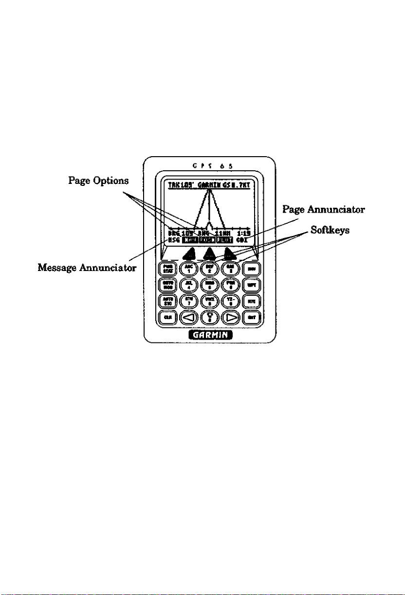
2.2 SOFTKEY OPERATION Information displayed on the LCD is commonly referred to as a “page.’'
The GPS 65 works with softkey operation. At the bottom of the screen
is a list of page options. To select a different page, press the appropriate
softkey below the desired menu option. Please note that the menu
options must be highlighted in order to use the softkeys. On the bottom
line, extreme right, is the page eunnunciator, which indicates the current
p^e you are viewing.
2-1
Page 11

2^ CURSOR AND FIELDS
Cyclic Field
Confirmation Field
Bar Field
Rté^0 ►flctiviite'?
GflRMIN
_ __♦_____
KVflP 178* 1.83
Tone H1S6 and Key
Change Contrast?
CLIFF 263^ 3.51
HftRBCK 330* 5.05
MIDRMR 0^2* 5.00
ftTE
The area of the page which is highlighted in reverse video is called the
cursor. The cursor may be moved to locations on the page called Reids
which allow you to enter data or change options. You will encounter five
types of fields.
- Numeric Reids accept numbers only,
* Alphanumeric fields accept numbers as well as letters.
* Cyclic Reids allow selection from several available options. A
^clic field is preceded by a prompt!^). You may cycle through the
choices by pushing CLR.
* Confirmation fields allow you to indicate your approved. For
example, you will be asked to confirm that you want to delete a
wa3rpoint. Confirmation fields always end with a character.
Press ENT to approve the confirmation field.
Backlight Timeout:
30 seconds
* Bar fields allow an adjustable scale entry with the length of the
bar representing the minimum to maximum setting. Use your
arrow keys to make adjustments in bгu■ fields.
2.4 KEYPAD OPERATION
PWR
STAT
2-2
The PWR/STAT key is a dual function key that controls unit
power and system status. Pressir^ this when the unitis off will
turn the unit on. To turn the unit off, press and hold PWE/
STAT imtil the display is blank.
Pressir^PWR/STATmomentarity while Uie unit is on will take
you to the status pages (see Section 3.2). If the message
annunciator is flashing and the tone sounds, you may push
PWR/STAT to view the message.
Page 12

"go t o
Hoe
Pressing GOTO/MOB once allows you to initiate the GOTO
function, setting an instantaneous course to any waypoint
(see Section 3.7). Pressii^ GOTO/MOB twice allows you to
initiate the Man Overboard function, setting an immediate
course to the captured position (see Section 3.9).
AUTO
STO
KAV
&
@
©
V * V alphanumeric field allows you to change the backlight level.
Pressing AUTOSTORE allows you to capture your present
position instantaneously (see Section 3.6).
Pressing NAV selects the Navigation Pages which allow you
to view navigation information and the Plot Page (see Section
3.8).
Pressing WPT selects the Waypoint Pages which allow you to
create, edit, delete, and rename wa3rpoints. In addition, you
may view nearest waypoints or proximity waypoints (see
Sections 3.4,3.5 and Chapter 5).
Pressii^ RTE selects the Route Pages which allow you to edit,
review, activate, and delete routes (see Chapter 4).
Pressing either of the arrow keys allows you to move
the cursor, scroll through information lists, and enter
letters of the alphabet.
/'yz^ The alphanumeric keys allow you to enter letters and
numbers. Use the arrow keys to select the desired
letter or number.
Pressing this key while the cursor is not on a numeric or
There are two backlighting levels.
J Pressing CLR erases information in the cursor field. If the
CLR
cursor is over a cyclic field, pressing CLR will toggle through
severed aveiilable options.
Pressing ENT confirms an entry or selection.
2-3
Page 13

2.5 ENTERING DATA
To enter data you must first move the cursor under the desired field by
pressii^ the ri^t or left arrow key.
To eater a number»
‘ Press the key that is labeled with the desired number. The
numbers will fill in from the riiditside of the field andmove to the
left as each new nvimber is entered. For example, if you wish to
enter “51” in a three space field, you must press the 5 and 1 ke^
in that order. NOTE: To enter a number into an alphanumeric
field, press the desired key followed by two presses of either the
right or left arrow key.
- Press CLR if you enter an incorrect number.
■ Press ENT when you have filled all significant digits of the field
with numbers.
To enter a letter»
* Press Üie key that is labeled with the desired letter.
- Press the right or left arrow key until the desired letter is
displayed.
• Press CLR if you enter an incorrect letter.
■ Press ENT when all the characters are entered.
The GPS 65 features a keypad feedback tone which will sound each time
you press a key. If you enter data which is not appropriate for the field,
the feedback tone will quickly sound three times indicating an error.
The keypad feedback tone can be turned offifyou wish (see Section 6.6).
2.6 VIEWING MESSAGES
From time to time, the GPS 65 will use a message to tell you of conditions
needing attention. When the GPS 65 has a new message, the MSG
annunciator will flash. When this occurs, press PWR/STAT to view the
new mess£^e(s). Press PWR/STAT again to see the page you were
viewing prior to reading your message.
While the MSG annunciator is flгlshmg, the GPS 65 will also generate
a tone to alert you of the message. (If your unit is connected to an
external alfum, it will also be activated.) Messages that demand
2-4
Page 14

iimnediate attention such as an arrival alarm generate a quick tone Uiat
will not stop until you view the message. All other messages generate
a slow tone that will cease after 15 seconds. The messi^ tone may be
turned off if you wish (see Section 6.6).
Important messf^es will remain on the Messeige Page after being
viewed. If this occurs, the MSG annunciator will be in view but will not
flash (if no messages exist, ftie MSG anmmciator will not be visible). To
review these messages, press PWR^TAT to reveal the status menu
options. Then press flie key underneath the "AUX” page option. With
the arrow keys, scroll to ‘Idessages* and press ENT.
Refer to Appendix A for a complete Ust of GPS 65 messages.
2.7 OPERATING MODES
Three modes are avmlable which will allow you to operate your GPS 65
in the way which best suits your needs (see Section 6.1).
Normal mode should be selected for most appUcations, especially high
dynamics operations.
Battery Saver mode is available for applications where vehicle battery
life or current drain is critical.
Simulator mode allows you to simulate the operation of the GPS 65
while on board (and moored), parked in your vehicle, or at home using
the optional AC adaptor. The simulator mode can be tised while
leamii^ to operate your GPS 65 and is ideal for plannii^ routes and
entering waypoints. Keep in mind that the GPS 65 is not tracking
satellites in the simulator mode. YOU SHOULD NEVER ATTEMPT
TO USE THE SIMULATOR MODE FOR ACTUAL NAVIGATION.
If you are using your GPS 65 for the first time, you are encouraged to
review Chapter 3 which introduces the GPS 65's basic features, and
Chapter 6 on custom setups. Afterward, you may want to read through
the rest of this manual and make further use of the built-in simulator
to practice with the advanced features.
2-5
Page 15

CHAPTERS
BASIC OPERATION
3.1 POWER ON
After you turn your GPS 65 on. It will conduct a series of self tests and
display the following notice:
Welcome to GHRnXN's
GPS 65
Globali HciMÌgcitor
SOFTHARE UER$I«H1.24
COmiGHT 1992
CftRHIM OORF
Following completion of the tests, the Satellite Bar Graph Page (see
Section 3.2) will be displayed, and the GPS 65 will begin acquiring
satellites.
After a position is found (and if no keys have been pressed), the Position
Page (see Section 3.3) will be displayed, and the unit is ready for normal
operation.
When four or more satellites with good geometry are available, the GPS
65 will automatically operate in the 3D mode in which latitude,
longitude, and altitude are computed. If only three satellites are
available, the unit will operate in 2D mode in which only latitude and
longitude are computed. When operating in the 2D mode, the emit will
use the last computed altitude or your last entered altitude. (Section 3.3
describes how you may enter the altitude.)
Your GPS 65 will automatically update satellite orbital data as it
operates. If you have not operated your unit for a period of six months
or longer, it vrill take approximately 15 minutes to search Uie sky and
collect new orbital data. You will be informed when your unit is
searchii^ the sliy with the message “Searching (he Sky." Once satellite
orbital data is collected, it will be stored in memory. The memory is
maintained by an internal battery, therefore the data will not be lost
when you turn your GPS 65 off.
3-1
Page 16

3^ SATELLITE STATUS PAGES
There are four statue pages available by pressing PWR^TAT, Three
pages display satellite tracking status, and the fourth is a menu of
auxiliaiy functions (messages, setups, and utilities). The softkeys at the
bottom of each page allow selecting pages: BAR (bar graph), STAT
(status), SKY (skyview), and AUX(auxUiary menu). You may also cycle
throu^ these pages by repeatedly pressing PWR/STAT.
simuiciting NciMigcitioii
ÏÏ3 12 17 21 23 2G 2B —
LTTrtT
* To view the
Sateilite Statue
Page,preee
eoi№ey
underneath the
STAT banner.
Simulating Nat;jgcition
DOP 2.e EPE
D3 17B' 25' 5
12 127* ID' 1
17 113' 73*
21 252' 3D' 5
E:hF; L'KV
* PrewSrgySo/ifay
7b
Satellite Sl^iew.
23 332* EB' a
2G D4B' 2G' 4
2B 3DD' 2B* 4
I STAT
jjUL
Satellite Bar Graph
The Satellite Bar Graph shows the
signal qtiality of each visible satellite
graphically. The receiver status is
also shown at the top of the screen.
In this example, the unit is
simulatingnavigation. The satellite
numbers (1-32) are represented
alongthe bottom ofthegr£q>h; signal
quality (1) weakest to 9, strongest)
is represented along the side. If a
satellite is visible but not tracked,
the signal quality will be blank. If
differential corrections are available
for a satellite, a “D* will appear at
the bottom of the signal strei^th
bar for that satellite. (See Section
6.7 for DGPS setup instructions.)
Satellite Status Pi^
The Satellite Status Page shows tiie
ID, azimuth, elevation, and signal
quality of each visible satellite in a
table format. The receiver status,
again, is displayed at the top of the
screen, as well as the dilution of
precision (DOP) and estimated
position error (EPE). (For more
information about unfamiliar terms,
see Appendix B.)
3-2
Page 17

•PrtwAUX
St^ikey to
dispto^ the
Auxiliary Menu
Page.
Op Mode Plotting
UnitsiHdg nictrinlCDI
Date ¡Time Audio !D$p)
Intrtace Map Datm
Bon Rcvr Sun Plan
Trip Pian Messages
nux
Satellite Skyview
The Satellite Skyview Page shows
the azimuth and elevation of each
visible satellite in a graphicslQ^ew
format. Additionally, the DOP and
EPE are displayed. The azimuth
and elevation are useful in
determining whether a satellite
signal is blocked by buildings,
mountains, or other obstructions. If
a satellite is not currently being
tracked, it will be displayed in
reverse video on the screen
Auxiliary Menu
The Auxiliary Menu Page enables
the selection of various setup and
utUify functions by moving the
cursor to an item with the arrow
keys and pressing ENT. Each setup
aiulutility page is described in detaU
in Chapter 6.
3,3 PRESENT POSITION
irkSSO'^gs 10^
N 38^53.329’
H094°40.582’
»nititude 108Pt
___
USDBaEEgiiiijL
Posititm Page
As mentioned earlier, the Position
Pf^ is automatically displayed once
a position is obtained. This page
displays track, ground speed,
latitude and loi^tude relative to
the selectedmap datum (see Section
6.8), as well as a choice of altitude
above mean sea level (MSL) or time
(cyclic field). (Note: Time
information will not be displayed
when the GPS 65 is acquiring
satellites.)
3-3
Page 18

When the GPS 65 is performing 2D navigation, the last known altitude
will be used in the latitude/loi^tude computation. If the altitude is not
accurate within a few hundred feet, you should manually enter your
altitude.
To enter the altitude (2D only)».
• Use an arrow key to move the ciursor under the altitude.
• Enter the altitude. If your antenna is mounted on a high mast,
make sure you add the mast he^ht. (Remember to complete the
data entry by pressing ENT.)
During initial satellite acquisition, the displayed position is the last
computed position stored in the GPS 65. If your position has moved
several hundred miles or more with the power off, tiie unit may go into
the AutoLocate™ mode. This process can take up to ten minutes.
Alternatively, you may enter a more accurate initial position to speed up
the acquisition process. (You may also chEinge the position at any time
while you are in simulator mode.)
To enter the latitude/loiigitude.»
■ Use Em arrow key to place the cursor on the latitude hemispheric
designation (far left).
• Check the hemispheric designation (“N” or “S") of the latitude. If
it is correct, go to the next step. If it is incorrect, press CLR until
the correct hemispheric designation is displayed.
- Place the cursor on the latitude field Emd enter the latitude.
Depending on the position format selected (see Section 6.3), you
will enter the latitude in one field (degrees only), two fields
(degrees/minutes), or tiu*ee fields (degrees/minutes/seconds or
UTM). You must press ENT for each field to confirm the data
entry.
• Check the hemispheric designation (“E” or “W”) of the longitude
in the same manner as above for latitude.
• Enter the loi^tude (remember to complete the data entry by
pressing ENT).
3A
Page 19

3.4 WAYPOINTS
The GPS 65 allows you to create, store, and use 250 alphanumeric
waypoints. A waypoint consists of a name (up to six letters and/or
ntimbers), its latitude/longitude location, last time/date ofmodification,
and a one-line comment. There are four waypoint pages. The softkeys
at the bottom of each page allow the selection of each page: Wl^
(waypoint definition), NRST (nearest waypoints), PROX (proximity
waypoints), and LIST (waypoint list). To start the waypoint pages,
press WPT. The Nearest and Proximity Waypoint pEiges are covered in
Chapter 5.
Waypoint Definition
If you are not already on this page,
HPT:G№MIH
N 38*56.995*
W094*44.782*
»DATEv^TIHE
31-DEC-S9 ee:ee
HPT
press the WPT softkey. It allows
you to review, create and modify
waypoints. The cyclic field allows
you to display one of the following;
1) the date and time the waypoint
location was last modified, 2) a oneline comment of the waypoint (up to
20 characters), or 3) range and
bearing from a reference waypoint
To create, modify or review a waypoint
* Move the cursor to the waypoint name field, then enter the
desired waypoint name.
- To create or modify position, enter the waypoint latitude and
longitude as describe in Section 3.3 on the previous page.
(NOTE: If a waypoint is being used for navigation, its position
cannot be modified. An attempt to modify the position of such a
waypoint will result in the message “Can't Chg Activ WFT.’')
3-5
Page 20

3,5 WAYPOINT UST
The Waypoint List Page allows viewii^ of the stored waypoints in the
unit, liie list may be scrolled, with the arrow to view all the
waypoints. FVom this page, waypoints may be selected for deletion,
renaming, or to activate a direct GOTO. (See Section 3.7.)
CLIFF GARMIN
To delete a waypoint,..
KRULL KVAP
MIDAMR MOB
RZRBCK WIDMER
* With the arrow keys, place the
cursor on the desired waypoint.
- Press CLR and ENT.
WLDCAT WPTl
WPT2
__
amvmawMLisj
NOTE: If you attempt to delete a proximity or route waypoint, a
message will be displayed. You must delete the proximity alarm or the
route before you can delete the waypoint.
To rename a waypoint.«
* With the arrow keys, place the cursor on the desired waypoint.
- Type in a new name for the waypoint and press ENT.
• The Confirmation Page is displayed. Press ENT to confirm the
name change or CLR to cancel.
3,6 AUTOSTORE
The AutoStore function allows you to capture your position at Uie
touch of a button for future reference. This function saves your current
position in a waypoint. Additionally, you may record your navigation
path by inserting the captured waypoints into a route (see Section 4.6).
- The Confirmation Page is
displayed. Press ENT to confirm
or CLR to cancel.
The AutoStore'''*' Pг^ displays the waypoint name, captured position,
and optional stors^ route. An AutoStore waypoint name is pre
assigned as a three digit number. You may change this to any name you
desire. Autostore''“ waypoints may be used for any waypoint operation
and wiU be part of the 250 available waypoints.
3-6
Page 21

The AutoStore™ Page displays the waypoint name, captured position,
and optional storage route. An AutoStore waypoint name is pre>
assigned as a three digit niimber. Youmaydiai^thistoanynameyou
desire. Autostore™ wajfpoints may be used for any waypoint operation
and will be part of the 250 available waypoints.
AUTOSTORE
/^aypoint Name
MPT:BBB
H 39°BB.
Append to Route
To capture present position.»
* Press AUTOSTO. The pre-assigned waypoint name is on line 1.
NOTE; The AutoStore™ location is captured as soon as you press
AUTOSTO. This allows you all the time you need to change the
waypoint name and/or confirm the Autostore.
* If you wish to give the waypoint a different name, move the cursor
to the waypoint name field and enter the name of your choice.
Press ENT. If you enter a waypoint name already used, you will
be informed with the message, *YVTT Exists fnameL* Enter a
different name if this occurs.
* Press ENT on a blank route storage number field to save the
waypoint. If tiie route storage number field is not blank, the
waypoint will be added to the route shown. (In Chapter 4, we will
discuss building a route with AutoStore.)
-Longitude
-Latitude
^Route StoTEige
Number
3.7 GETTING THERE FAST-GOTO
The GOTO fimction allows you to quickly set a course finm your position
to any waypoint.
GO TO:
HIDMER
-Tmp«* woppoint name ta
chans« 4«itinati«n.
-Vftss IfDO ta reset man
euerboard position.
-Press ЕИТ to actiuate
GOTO naoisation.
_____
3-7
Page 22

To activate the GOTO function...
• Press GOTO. The above page will be displayed with the cursor on
the GOTO waypoint field. If the GPS 65 is currently navigating
to a waypoint, that waypoint will be offered as the default GOTO
waypoint. If the waypoint field is blank or the waypoint shown is
not the desired destination, type the new name ri^t over the old
name. NOTE: If a non-existent waypoint name is entered, the
Waypoint Definition Page will appear to give you the opportunity
to create the waypoint (see Section 3.4).
■ Confirm the default GOTO waypoint by pressing the ENT key.
The NAV Page will be displayed. (The D-Bar on the GDI will be
re-centered at this point, see Section 3.8 below.)
Alternatively, the GOTO function may be quickly activated from many
pages (e.g. the Nearest Waypoint Page or the Waypoint List) by placing
the cursor over the desired waypoint name and pressing the GOTO key.
The GOTO Page will be displayed with the cursor on the GOTO
waypoint name. The (X)TO fimction will be activated when the ENT
key is pressed.
To cancel the GOTO fimcti<m.»
■ E*ressGOTO.
' Press CLR. The (JOTO waypoint name will become blank.
‘ Press ENT. The GPS 65 will start to navigate using the active
route, if it has been programmed (see Chapter 4). Otherwise, the
GPS 65 will stop computing waypoint navigation data.
3.8 NAVIGATING TO A WAYPOINT
There are four nav^tion pages available fiem the NAV key. You may
cycle throng the following with softkeys at the bottom of each page:
NAV (navigation summary), CDI (graphic course deviation indicator),
PLOT (graphic plotter), and POSN (l4esent Position Page).
—■^-isoTO-esRHiH
Cychc Fields
D-Bar
Relative
Bearing Pointer
3-8
>BR«107MtNC 10.5
A.0 _ A- l.D
■
MHimiMIglil MRU
Cychc Fields
10.0^
' Scale Setting
Course Deviation
Indicator (CDI)
Page 23

Navigation Summary
The Navigation Summary Page displays direction, distance and speed
information to direct you along a route or a GOTO destination. The
active leg(route) waypoints or GOTO waypoint is shown at the topof the
screen. The GDI is at the bottom of the page. Current CDl scale setting
is shown at each end of the scale. This is replaced by the cross track
distance if the D-Bгtr goes off the scale. A relative bearing pointer at the
center of the CDI indicates Gie bearing to the waypoint relative to the
current track (TRK).
Notice that this pa^ has four cyclic
GO TO GARMIH
.ш1в7»>«10.5
fields available. The field options
are as follows:
Field #1 (top left) provides a choice
of: (a) bearing to destination
>ткк126>с: IB.8
l.D Jt 1-0
■ ■ • e • « • «
1дм;ндта1ка1 ым
* Prêts the softkty
under CDI.
waypoint (BRG), (b) course to steer
(CTS), (c) desired track (DTK),
ground track (TRK), or (e) turn
(TRN).
Field #2 (top right) provides a choice
of: (a) range todestination waypoint
(RNG), (b) cross track error (XTK),
(c) aloi^ track distance (ATD), or
(d) distance made good, back to
starting point (DMG).
id)
Field #3 (bottom left) provides a choice of: (a) ground track (TRK), (b)
course made good (CMG), or (c) ground speed (GS).
Field #4 (bottom right) provides a choice of: (a) ground speed (GS), (b)
estimated time enroute (ETE), (c) estimated time of arrival (ETA), or (d)
velocity made good (VMG). (See Appendix B for a description of
navigation terms.)
TRKISE' CARHINCf IflKT
Course Deviation Indicator
The CDI Page shows a graphic
“highway” display. The active
waypoint is shown at the top of the
screen. Navigationvalues for Track
BRG oar RM Б.7МИ 45:85
1пш1Д1м;|1яю11 CDI
* Press the softkey
under PLOT.
(TRK), Ground Speed (GS), Bearing
(BRG), Range(RNG), and Estimated
Time Enroute (bottom right) are
shown. The center-line of the
highway represents the desired
3-9
Page 24

track. The outer lines give a perspective view of the distance to a
waypoint. As the waypoint conies into range, it will be displayed and the
outer lines will become parallel.
Tnn
*
llNtl
_______cu.
Press the POSN
softkey .
waypoint name by scrollii^ to the point with the arrow keys. A GOTO
may be performed by pressing GOTO while the cursor is on the
waypoint.
The scale distance for the screen (distance represented by height of
screen) is at the lower left comer of the screen. The scEile number
(directly above the scale distance) may be changed by moving the cursor
to the scale number and pressii^ CLR, or by entering a new number (0-
9). Finally, the Plot Pagecan be oriented as a “North up”, “Groimd Track
Up”, or “Desired Track Up” display (see Section 6.2).
MftU PA^M PLOT
A
Plot Pi^e
The Plot Page shows a graphic top
view of your course. The destination
waypoint is shown at the top ri^t of
the screen. Your present position is
shown as a plus sign in the
middle of the page. The track history
and/or the active route are shown as
a solid Une. (Plotting of ground
track and active route is userselectable, see Section 6.2.) Nearby
waypoints are displayed as
diamonds. You may view the
trk128°gs
N 38'58.257
H094°57.4EG’
»nititude lB8Pt
3-10
Position Pi^e
The Position Psige is described in
Section 3.3. Please refer to that
section for further information.
fOSH
Page 25

3^ MAN OVERBOARD
The Man Overboard function allows you to set an instantaneous course
to a captured position, providing rapid response to an emeigency
situation.
GO TO:MOB
-Tppe woppoint Mttit to
chongedf-stiROtion.
-fetes not to ctstt mon
ovorboord pOfitlOR.
-fetes EMT to octiuott
GO TO ROUiSOtiOn.
To activate the Man Overboard function...
- Press MOB twice. The above page will be displayed and the
present position will be captured in a waypoint named, “MOB.”
• Press ENT to nav^ate to the Man Overboard waypoint. A
navigation page will be displayed; select the desired page with the
softkeys.
3.10 SAMPLE TRIP
Now that you have gained a basic understanding of the GPS 65, you are
ready to етЬгигк on a sample trip.
Your GPS 65 is factory initialized with a position of N39“, W095“. A
waypoint named GARMIN, located at GAKMIN's Lenexa, Kansas
facility, is also provided.
Just for fun, let's go to GARMINi Turn on your GPS 65. The power on
notices will be displayed followed by the Satellite Bar Graph. The GPS
65 is ready to accept your commands.
3-11
Page 26

Op node Plotting
UnitsIHdg flIcirmiCDI
Dote {Time RudiolDspI
Intrface Map Datm
Ben Revr Sun Plan
Trip Plan Messages
AUX
Select the simulator mode».
• PressPWR/STATtoselectaStatus
Page.
* If the Auxiliary Page is not
displayed, press the softkey
underneath the AUX banner to
select it.
Plotting
UnitsiHdg flIarmiCDI
Date ¡Time Audio ¡DspI
Intrface Map Datm
Bon Rovr Sun Plan
Trip Plan Messages
____
SKY STAT BAB
f
s
OPERATING HOPE
^Simulator
FILTERS
Position Pautomatio
Velocity Pautomatio
TRK 288° GS0. B t
N 39°Ba.BBe’
PTime 18=22=46
___
gwinCTirni POSN
3-12
Use the right arrow key to
highli^t *Op Mode”, press ENT,
If the operating mode field does
not already display “Simulator”,
move the cursor with the arrow
keys to that field, and press CLR
until it does, followed by ENT.
The unit is now ready to start the
simulation.
Check the present position.»
• Press NAVto display a navigation
page.
• Ifthe Present Position Page is not
displayed, press the POSN softkey
to select it. Note the present
position. We will cheinge the
position to N39" W95". (If the unit
is set to display UTM coordinates,
refer to Section 6.3 to change the
coordinates to latitude and
longitude.)
Page 27

• Move the cursor to the latitude hemispheric designator with the
arrow keys. PressCLRifyouneedtochai^thisdesignatorfrom
“S” to “TT. Press ENT.
' With the cursor on the latitude d^rees, press “3” and then
ENT. (You may need to enter for minutes and/or seconds to
dear these fields, if they are shown.)
- Move the cimsor to the longitude hemispheric designator. Follow
the same sequence as above to complete longitude entry.
NOTE: The sample illustrations in this section assume that the factory
default settii^, including the selection ofnautical units (knots, nautical
miles), have not been changed. If these settings have been changed, the
unit may display sightly different data than presented here. Charging
the unit set-ups is covered later in Chapter 6.
Check the GARMIN waypoint«.
To verify that the “GARMIN”
waypoint is in memory, press WPT
to select a waypoint page.
If the Waypoint list Page is not
displayed, press the LIST softkey
to select it. Verify that the
waypoint, “GARMIN”, is on the
list. If it is, you may skip the next
three steps. NOTE: If the
Waypoint List Рг^ is full, use the
arrow keys to scroll through the
rest of the list until you locate the
“GARMIN” waypoint.
If the “GARMIN” wa)rpomt is not
listed, you must add it to the GPS
65's memory before you can
activate the GOTO fimction. E*ress
the WPT softkey.
Move the cursor over the waypoint
name field with the arrow keys.
Enter “G”, “A”, “R”, “M”, “Г, “N”.
Press ENT. Remember to use tiie
arrow keys to select the letter you
3-13
Page 28

want(e.g,, to get the letter “G”, press the "3" key and then Uie left
arrow).
Enter the coordinates for the "GARMIN” waypoint using the Mnift
method described for setting the present position (see Swtion 3.3).
Note, however, that depending on the unit setups, Lat/Lon
coordinates will be entered in one (degrees only), two (degrees/
minutes) or three (degrees/minutes/seconds) fields. These setups
are covered later in Chapter 6. Refer to tiie table below for the
proper location numbers to enter;
Setup
D^^rees Oidy
D^rees/Minutes
D^^ees/Min/Sec
Latitude Longitude
N38.94992“
N38“ 56.995’
N38“ 56* 59.r
W94.74638*
W94“ 44.782*
W94“44’46.9“
With the coordinates entered, you are ready to proceed with the
GOTO function.
GOTOGARMIN,„
• Press GOTO/MOB. The GOTO
Page is displayed with the cursor
tmder the C5OT0 waypoint name.
• Enter the waypoint name,
‘GARMIN” with the alphanumeric
keys and the arrow keys. Press
ENT.
Enter 'GARMIN' with
atpbanumeric umI arrow keys.
t
*PUuNAVi^ait^ifmKded
- A navigation page is then
displayed.
• If the Navigation Summary Page
is not shown, select it with the
NAV softkey.
GO TO GflRMIN
»R« lB0>Kiio 12.2
»TRKÍ00kG$ 0,0
1.0
PúíHIF'LOT!
3-14
1.1
MflU
Page 29

A Faster GOTO«.
At this point, we will take a very brief detour. You may recall from
Section that there is an alternative to typing all those letters in. Let's
try it.
‘ First we must cancel the existing GOTO by pressingGOTO/MOB,
CLR, and ENT. This calls up the GOTO Page, clears the
destination and then confirms that no GOTO destinafion is
desired.
cLiff
KVAP
MOB
GARMIN
MIDAMR
R2RBCK
WLDCAT WPTl
WPT2
liinglLKT
CLIFF
KVAP
MOB
iGhiRMINai
MIDAMR
R2RBCK
WLDCAT WPTl
WPT2
PROM Kits
GOTO:
-'Tjrpe woppoint name to
change deftination.
-Press not to reset mat
everboard position.
-Press EHT to dctiyote
00 TO naui^ation.
T HPT LIST
GñRMIH
Select the Wa3rpoint list Page by
pressii^ WPT and then the LIST
softkey, if needed.
With the right arrow key, move
the cursor to the GARMIN
waypoint.
PressGOTO/MOB. Thewaypoint
“GARMIN” is automatically
carried over to the GOTO Page.
CYou can “import” waypoints to
the GOTO Page from several other
pages, including the Nearest
Waypoint Page and the Plot Page,
simply by highh^tmg the desired
waypoint.)
3-15
Page 30

TstnrnsñmFT
»»RG 100 »RMG 12.2
»trk189»gs B.B
l.D 1.0
■ ■ ■ « ■
HBHüiamwai oru
Press ENT. A navigation page is
then displayed.
Select Uie NAV Svimmary Page
with the NAV softkey. Now back
to our trip.
GO TO Gf^RMIN
>RRg1BB>RHG 12,2
^RK 100
l.D
ms
MSM PLOT epi MRU
1.0
•I 01
Set the Simulation Speed...
* Wilh the arrow keys move the
cursor to the ground speed field.
(If this field does not currently
indicate "GS’', for ground speed,
highlight that field with the left
arrow key and press CLR until it
does.)
GO TO GARMIN
lee »RHG 12.2
^trkIBB^c^ 15. B
1.0 1.0
t
F-LOT
HflU
Enter a ground speed of 15 knots
by pressing “l^ “5", and ENT.
(The GPS 65 will accept speeds of
up to 90 knots.) The simulation
speed is now set and the GPS 65 is
simulating a trip from coordinates
N39“ W95“ to the “GARMIN”
waypoint (our Lenexa, KS facQity).
Examine the Navigation Information.»
At this point, you can explore the capabilities of the GPS 65. While you
are on the Navigation Summary Pгlge, you may want to examine other
information not currently displayed (see Section 3.8).
• As Üie unit is nav^aüng, you will notice the Range (RNG) to
GARMIN decreasing. If you wish to see the distance back to where
you started from, highlight this field (top r^ht) vrith the arrow
keys, and press CLR until distance made good (DMG) is displayed.
3-16
Page 31

‘ Highlight the ground speed (GS) field (bottom right) and press
CLR until the estimated time enroute (ETE) is displayed.
• Highlight the ground track (TRK) field (bottom left) and press
CLR imtil groundspeed (GS) is displayed.
• Highlight the bearing (BRG) field (top left) and press CLR until
ground track (TRK) is displayed.
You now have eui entirely different Navigation Summary Page that
should look somethii^ like this:
eo TO GARMIN
dsbIBB^diig 1.58
ms IS ►ETE 42:35
^ 1.0
• A • « ■ • ■
I^OSIITLOT CDl »ftU
Move the cursor to the page
options with the arrow keys.
Select the Graphic GDI Page with
the GDI softkey, (the “3” key in
this case).
T
GO TO GARMIN
►TRK iee.Dnc3.48
Mis 15‘E’e34:55
• « a ■ « A a a a a a
l.a A 1.0
l.D
mum
Let's Look at a Different Navigation Page».
rgigiraoguCTi hau
TftKiao' coftHiii« isKT
88G iaO~ ftMGT.THH 30:57
mai^iHaBn cdi
The Graphic GDI Page shows the
“highway" display. Note the
ground track (TRK), destination
waypoint, and ground speed (GS),
on the top line. On the bottom
line, beaiing (BRG), range (RNG),
and estimated time enroute(ETE),
are displayed.
3-17
Page 32

TRK 100° GS
IS'-t
N 38°58.G62’
H094°53.200’
^lime 15:25:50
F LuT
1СШро$и
Our Next Stop, the Preseut
Position Page.»
* Select the Present Position Page
with the POSN softkey. Note that
ground track (TRK) and ground
speed (GS) are shown on the top
line, followed by the current
latitude and longitude on the next
two lines.
TRK 100'^ GS 151
N 38°58.202’
H094°50.875’
►HltituiiJi-
PLOT 001
TRKiee^GS 15^
108rt
HAU FOSM
N 38^57949’
H094^49.593’
FRItitude 1981^t
_ __
аавшшшш
Highlight the cyclic field at Gie
bottom of the page and to^e
between current time and altitude
withCLR.
The Plot Page (last one)».
• Move the cursor to the page
options with the arrow keys.
• SelecttheHotPagewiththePLGT
softkey.
The Plot Page will plot your ground
track and/or an active route. (The
setups for this page are covered in
Section 6.2.) The top left comer
indicates a “Track Up" display. A
“North Up” display would be shown
as “000” and a “Desired Track Up”
display is also available. The top
right comer shows the destination
waypoint.
3-18
Page 33

IDD GARtllN
♦
IS
S.BHIl
1
«DI NAU P«SHRL«T
1
IDD
GARHIHH
»E
IINII
CDIrHAUP4SN PLOT
S
Experiment with your GPS 65.
GARMIH
❖
+
The scale settii^ is shown in the
bottom left comer.
* Highlight the scale setting field
with the arrow kej^ and change
the scale setting with CLR. You
may also change the scale settings
with the number keys (0-9).
Finally, you may identify any
waypoint shown on the Plot Page.
- Select a scale setting that allows
you to see the destination waypoint
(GARMIN).
• With the arrow keys, h^hlight
the waypoint shown on the Plot
Map. Once highlighted, the
waypoint name is shown.
You are on your way to masterii^ the GPS 65. If you let the simulator
run, you will eventually get a message, “Approaidui^ GARMIN”, just
prior to reachii^ the waypoint. Press PWR/STAT to view the message;
and again to return to the Plot Page.
You may also want to:
- Press NAV, WPT, GOTO, or any other key to become more
familiar with the available pages.
‘ Practice using the softkeys and cyclic fields to display new
information.
* Change the simulation speed (faster or slower).
* Read Chapter 6 on Unit Customization and set up the unit to your
preference.
- Stop the simulation. You can stop the simulation by turning the
unit off (press and hold PWR/STAT), or go to the “OP Mode” set up
and chгmge to the “Normal” or “Battery Saver” modes (see Section
6.1).
3-19
Page 34

CHAPTER 4
ROUTES
4.1 NAVIGATING USING ROUTES
POINT
The GPS 65 offers a route navigation feature for you to navigate aloi^
a pre-defined sequence of waypoints.
The GPS 65 route capability allows you to create and store ten routes,
numbered 0 through 9, containii^ up to 20 waypoints each. Routes 1 to
9, the storage routes, can be activated to travel either in the order you
defined the waypoints or in reverse order. Route 0, the active route, is
the route you are navigating. The waypoint toward which you are
navigatii^is called Uie “active to” waypoint. The waypoint immediately
behind you is called the “active from” waypoint. The line that connects
the “active from” and “active to” waypoints is called the “active leg.”
BUOY2
The GPS 65 features automatic leg selection which will select the route
segment closest to your position as the active leg. The GPS 65 also
featiires automatic leg sequencing. As you pass a waypoint in the route,
the unit will automatically select the next waypoint as the “active to”
waypoint.
4-1
Page 35

There are 3 route pages in the GPS 65. The softkeys at the bottom of each
page allow cycling through each page: RTE (route definition), ACTV
(active route), and LIST (route list).
4.2 CREATING AND COPYING A ROUTE
The Route Definition page allows you to create, chainge, review, copy,
and activate routes. Remember that route 0 is always the active route.
If you create a route in route 0, you should copy itinto an empty storage
route (1-9). When you activate a storage route 1-9, it will be copied to
route 0 for activation.
Route Defimtiou
Waypoint List
Route # Field
GfiRMIN
KVflP 178* 1.83
Route Action Field
___
.Desired
Track
CUFF 263* 3.51
RZRBCK 330* 5.05
illDftMR 0-12* 5,00-
RTE
Press the RTE key. If you are not already on the Route Definition Page,
press the RTE softkey. On the route niunber field, you may choose
between routes 0 through 9 with CLR. Next to this is another cyclic field
which allows you to activate the route, clear the route, copy the route to
another location, or invert the order of the waypoints in a route and
activate it The arrow keys allow you to scroll through the list of
waypoints in a route.
‘ Move the cursor to the route
RteH ►Activate?
♦
♦
4-
■fr
LIST
flCTU RTE
number field and press CLR until
you find an empty route.
Scroll to the first blank waypoint
name field and type in a waypoint
you wish to put in the route.
Press ENT.
Repeat this process for each
waypoint you want to add, up to a
total of 20.
' Leg Distance
To Create a Route.»
4-2
Page 36

To copy a route...
Rte>0 HWBRIWiH
< Select the Route Definition Page
(RTE).
GBRUIN
KVfiP 178* 1.83
CLIFF 263* 3.51
RZRBCK330* 5.05
MIDRMR
____
LISL,
A third field now appears in the top right comer. Highlight this
field and select the destination route number with CLR.
Press ENT. The route is now copied.
4.3 ACTIVATING ROUTES
Routes are activated on the Route Definition Page also. You may
activate any route in the displayed order, or in reverse order. (NOTE:
Remember, when a new route is activated, the previous contents of
route 0 will be overwritten. If you wish to save route 0, be sure to copy
it to an empty route first.)
Rte^l
GflRMIN
KVflP
CLIFF
RZRBCK
MIDflMR
LIST
042* 5.00
fttm RTE
___*_____
178*
263*
330*
042*
1.83
3.51
5.05
5.00
ftCTU ME
* Highlight the route number field
and select the route number to
copy from with CLR.
* Highlight the route action field
with the arrow keys and press
CLR until “>Copy To>" is
displayed.
To activate a route...
' Select the Route Definition Page
(RTE).
• Highlight the route number field
and select the route number to
activate with CLR.
• Highlight the route action field,
and with CLR select “>Activate?”.
^ I n r t ?
GRRMIH
KVflP 173* i;S3
CLIFF
RZRBCK
263* 3,51
330* 5.05
MIDRMR 042* 5.00
LIST ACTU RTE
• Press ENT to activate the route.
To invert a route...
• Follow the same steps as above for
activating a route, but select,
“>Invert?” at the route action field.
• Press ENT to activate the route in
an inverted order.
4-3
Page 37

4.4 EDITING ROUTES
I RteH ►Activate? I
To Edit an Efxisting Route».
GARMIH
IKVAPH
178^ 1.83
CLIFF 263* 3.51
RZRBCK330* 5.05
mt^AMR 042* 5.00
____
_____
LIST
flCTU ItTE 1
1 RteH ►Activate? I
1 GARMIH
275* 83.0
KVAP 094*
CLIFF
263* 3.51
89.3
RZRBCK 330* 5.85
LIST ACTU RTE 1
• If you attempt to add a waypoint to a route that Eilready contains
20 waypoints, you will be informed with the message, "Route is
Fuir.
NOTE: You may also edit a route from the Active Route Page (see
Section 4.6).
• Select the Route Definition Page
(BTE).
• Hi^iUght the route number field
and select the route you wish to
edit.
• To insertawaypoint into the route,
highlight the waypoint you want
to place the new waypoint in firont
of. Type in the new waypoint
name. Press ENT. The new
waypoint is added to the route.
• To delete a waypoint from the
route, highlight the waypoint you
wish to delete. Press CLR and
ENT.
4.5 DELETING ROUTES
You may delete an unweinted route from the Route Definition Page.
To delete a route...
1 Rte^0 LU№U
GARMIH
4
KVAP 178* 1.83
CLIFF 263* 3.51
RZRBCK 330* 5.05
MIDAMR 042* 5.00
LIST
____
ACTU ATE
4A
__
Highlight the route number field
and select the route you wish to
delete with CLR.
Highlight the route action field
and select ">Clear?” with the CLR
key.
Press ENT to delete Hie route.
Page 38

4.6 ACTIVE ROUTE
Active Leg
_ _ _
■RZRBCK^MIDflMR
Range
RHG“^ETE-
Waypoint List-
MIDflMR 2.76 1:33
GRRMIN 8.20 4:38
The Active Route Page display the waypoints of the active route
starting with the “active from” and “active to” waypoints on the top line.
Press the ACTV softkey to select this page.
The Waypoint List displays route waypoints startingwith the “active to”
waypoint. For each waypoint, additional information is available. The
first column displays Range (RNG). The second column is a cyclic field
that displays Estimated Time Enroute (ETE, in hours/minutes or
minutes/seconds, as appropriate), Estimated Time of AnivEil (ETA), or
Desired Track (DTK). You may scroll through the waypoint list with the
arrow keys.
To edit the active route...
• To insert a waypoint, h^hlight the waypoint you want to place the
new waypoint in front of. Type in the new waypoint name. Press
ENT. The new waypoint is added to the route.
■ Cyclic Column:
- ETE
-ETA
-DTK
• To delete a waypoint, highlight the waypoint you wish to delete.
Press CLR and ENT.
4.7 ROUTE UST
The Route List Page displays a list of all routes currently stored in
memory. PresstheLISTsoftkeytoselectthispage. The Route List Page
displays the route numbers (far left), begimiing waypoint, and final
destination waypoint. You may гdso activate or delete a route from the
Route List Page.
4-5
Page 39

eGftRrilH/GflRIlIH
1маад1нвнадд|Ц|
2WPT1 /WPT2
3
_______/_______
4
_________/_________
5
_______/_______
____
ши_______КТЕ LIST
Highlight the route you wish to
activate with the arrow keys.
Press ENT. The Route Definition
Page is displayed with the
“>Activate?* action highlighted.
Press ENT to Activate the route.
To Activate a Route...
To Delete a Route.«
' HigiU^t the route you wish to delete with the arrow keys. Press
CLR. The Route Definition Page is displayed with the *SClear?”
action highlighted.
• Press ENT to delete the route.
Building Routes with AutoStore».
The GPS 65's AutoStore*™ feature is the quickest and easiest way to
build a route as you go. With autostore, each time you turn on a new
track, pass a significant landmark, or reach some location of interest,
you can save the location and create a route at the same time. Each
autostore wa3rpoint can be added to the same route as you are traveling.
AUTOSTORE
ирт:еве
H 39°ee.eee’
fltopend to Routel^H
Select an empty route to store the waypoint into by highlighting
the "Append to Route >_?” field and pressing CLR until the desired
route number is displayed.
Press ENT to add tbe waypoint to the selected route.
Repeat these steps each time you arrive at a location you wish to
add to the route, up to a total of 20 waypoints per route.
4-6
* With the unit operatili in 2D or
3D Navigation mode, press Üie
AUTOSTO key to save your
starting location.
• At this point, you may change the
AutoStore name, if you wish (see
Section 3.6).
Page 40

CHAPTERS
ADVANCED WAYPOINT FEATURES
5.1 NEAREST WAYPOINTS
An important feature of the GPS 65 is the ability to display up to nine
nearest waypoints, within 100 nautical miles of your present position.
In an emei^ncy, you may use the nearest waypoint featme to find the
closest point of safety in your area. As was discussed in Section 3.4, you
may access the waypoint pages by pressing the WPT key.
IMOB 277*0. SR.
2 RZRBCK
267*3.2R.
SMIDflMR 803*3.5R.
A
GRRMIN101*3.7R.
5 CLIFF 188* 4. GR.
GKVftP 14G*5.0R.
■lainfeHiaanBiiiitiT
To GOTO a Nearest Waypoint...
• Move the cursor to the desired waypoint name with the arrow
keys.
• Press GOTO and ENT.
5.2 PROXIMITY WAYPOINTS
The Proximity Waypoint Page allows you to define an aleirm circle
around a waypoint. This feature is useful in defining an area around a
rock, reef, or restricted waters. When you approach one of these
waypoints, the GPS 65 will notify you with an alarm tone and the
message, “Prox Alarm-[waypoint name],” if you enter the alarm circle.
If the Nearest Waypoint Page is not
currently displasred, press the NRST
softkey. This page displaj^ the
waypoint names including bearing
and range from present position.
You can scroll through the
waypoints listed by using the arrow
keys.
1 GARMIN 1.0R.
2 RZRBCK
3 WLDCfiT 20.0R.
A
______
5
G
0.5R.
...
——.
The GPS 65 allows you to define a
n
n
h
maximum of nine proximity
waypoints. Scroll through the
proximity waypoint list using the
arrow keys.
5-1
Page 41

To set a proximity waypoint.»
' Select the Proximity Waypoint Page with the PROX softkey.
’ Select a blank waypoint name field with the arrow keys.
‘ Enter the waypoint name, (NOTE: Ifneither the waypoint name
nor the location exists in memory, the Waypoint Definition Pгlge
will be displayed. Youmustthenenterthewaypointlocation. See
Section 3.4 to create a waypoint.)
• IVessENT.
- Enter the proximity alarm distance.
* Press ENT to enable proximity alarm.
If the newly created proximity alarm circle overlaps with an existing
proximity alarm circle, you will be informed of the overlap with the
message “Proximity Overlap”. As lon^ as the overlap remains, this
message will be displayed each time the GPS 65 is turned on. (WARNING:
If you enter the overlap area, the unit will only inform you of the neamst
waypoint.)
5.3 REFERENCE WAYPOINTS
In section 3.4, we discussed creation of waypoints by entering the
latitude and longitude position. Another way to create a waypoint is by
referencing an existit^ waypoint. By indicating the bearing and range
from a reference waypoint, the GPS 65 is able to compute a latitude and
longitude location for the new waypoint.
To create a waypoint by
HPT:KMCI
N 39M7.960*
W094M3.080'
►«F:6flRMIN
6M=000* RN<i= 21.0R.
hpt
Highlight the “>Ref:” field and enter the existing waypoint that
will be used as reference, (If the reference field is not currently
shown, highlight that cyclic field and press CLR until it is
displayed.)
Press ENT.
5-2
referencii^ another».
Select the Waypoint Definition
Page with the
Highlight the WPT mime field and
enter the new waypoint name.
Press ENT.
WPT
softkey.
Page 42

Enter the bearii^ and distance from the existing waypoint to the
new waypoint.
Egress ENT. Alatitude and loi^tude location for the new waypoint
should now be displayed.
5.4 WAYPOINT SCANNING
Throughout this manual, each time we have encountered a waypoint
name field, we have entered the waypoint name with the alphanumeric
keys. An alternative is to use the wa}rpomt scanning feature.
To Scan for a Waypoint.»
As an example, use the GOTO
GO TQ:|
-Tppe woppoint nome te
change destination.
-Press tlOi to reset man
overboard position.
-Press ENT to activate
GO TO navigation.
• Press WPT, A waypoint name is now displayed.
• Scan for the desired waypoint with the arrow keys. (NOTE; As
you are scanning, up to nine neEirest waypoints will be shown first;
followed by the entire list in numeric and alphabetical order.)
waypoint field. Press GOTO.
The waypoint name field is
highlighted and may be blank or
may already show a GOTO
destination. Ifthewaypointname
field is not blank, press CLR.
To limit the scaiming range, you may specify the first letter(s) or
number(s) of the waypoint name.
To Perform a Limited Scan.»
For this example, select the
HPT:
N
W.
►REF:
_________
SRQ:__* RNG:
___
LIST PROM NRST HPT
Enter the first character of the waypoint name. For this example,
enter the letter “G”,
Press WPT, Use the arrow keys to scan through all waypoints that
begin with the letter “G”.
_____
Waypoint Definition Pi^e with
WPT and the WPT softkey, if
needed.
Highlight the waypoint name field
with the arrow keys.
If this field is not blank, press
CLR.
5-3
Page 43

CHAPTER 6
AUXILIARY FUNCTIONS
Op Mode Plottin9
Units IHdg flIctrmICDI
Date ¡Time fludiolDspI
Intrtace Map Datm
Ben Revr Sun Plan
Trip Plan Messages
■aawaMiaiimjl nuM
The GPS 65's auxiliary pages allow you to do utility and setup functions
to customize your unit. The 11 audliaiy pages are accessible from the
auxiliary menu (see Section 3.2) by highlighting the page you want and
pressing ENT. The softkeys allow changing to previous (PREV) and
next (NEXT) pages. The AUX softkey takes you back to the Auxiliary
Menu Page.
0.1 OPERATING MODE AND FILTERS
---------
«»ftATIN« mi
--------------------
^Simulator
FILTERS
Position ^automatic
Velocity ^automatic
Also from this page, tiie position and velocity filters may he changed.
Changing the filter settings will alter the GE*S 6S's response time to
changes in track or groimd speed. To change the filter settings,
highlight the appropriate field and cycle throu^ the filter settings
(automatic, fast, me^um, and slow) with CLR. The “Fast” setting will
provide instantaneous response (three seconds maximum response
time) to changing conditions. The “Medium” (approximately 20 seconds)
OT “Slow” (approximately 120 seconds) settings may be more desirable
for slow speed operation where frequent ground track changes will
occur (e.g. sailing or hiking). It is highly recommended that you select
the “Automatic” setting for most applications.
From this page, you may change
between various operating modes
by h^hli^ting the “OPERATING
MODE^fieldandpressingCLR. You
may select simulator mode, normal
mode, or battery saver mode. (See
Section 2.7 for a description of each
mode.)
6-1
Page 44

GJZ PLOTTING SETUP
---------------
рсшш
------------------------
Orientation ►Horth up
^Route and Track
^Interval: вО^Ов^Зв
Track»-wrap Clear?
Memory Used Ox
___
ДЯД1И)И1:ыш
of a route (DTK Up). To select the desired option, highlight this field and
press CLR. Your present position and nearby waypoints are displayed
on the plot map at all Umes. The second cyclic fi^d determines what
additional information will be displayed on the plot map. You may
display the active route and a stored ground track showing where you
have been, only the active route, only the ground track, or neither.
The ground track is stored at a frequency that you can define either by:
Time Tnterval”, “Resolution’’, or’TKstance’’, Select the desired frequency
unit by highlighting this field and pressing CLR.
______
The Hotting Setup Page is used to
configure the Hot Page and select
the types of information that will be
displayed. The first cyclic field
defines the orientation of the plot
map. Thetopoftheplotmapmaybe
North (North Up), the direction of
your current ground track (TRK
Up), or the direction of the active leg
To store the Ground Track at selected time Intervals.»
■ Highli^t the storage frequency field (third line) and select
“Interval” with CLR.
• Press ENT.
' Enter the time interval between stored positions startii^ with
hours, then minutes, then seconds. Press ENT after entering data
in each numeric field.
To store the Ground Track by Distance».
• Hig^^ht the storage frequency field and select “Distance” with
CLR.
• Press ENT.
• Enter the distance, and press ENT, When your position moves
this distance in any direction, a new position is added to the stored
ground track. NOTE: “Distance” storj^ may be preferable to
“Resolution” stori^ if the ground track will include a lai^
number of turns.
6-2
Page 45

If the planned course will be primarily strai^t line travel, you shotUd
select ^‘Resolution” storage. In this application, considerably less
memory is used for the same distance traveled.
To store the Ground Track by Kesolutiw«,
• HighlifidttthestoragefrequencyfieIdandselect‘‘Resolution”with
CLR.
• Press ENT.
• Enter the resolution rai^, and press ENT. When your position
moves this defined range offaprojected courseline, anew position
is added to the stored ground track.
The track storingfunction may be turned on andofTby hi^dightingthe
‘Track>” field find pressing CLR. From this same field, the track may
be set to Vrap” around through available memory (deleting the oldest
track information and using the memory to store the new track
position). The amount of memory, used at any given moment, is shown
on the bottom line. When available memory is filled or the track is no
longer needed, it may be cleared by highlighting *‘Clefir?” and pressing
ENT.
6.3 UNTTS/HEADING SETUP
UHlTf / HEAD»«
Posn ^hddcl^min.inmm'
Hav ^nciutical
Hd9 ^tiuto mtig
degrees and minutes (hddd**mm.mmm*); degrees, minutes and seconds
(hddd'’mm’ss.s”); UTM/UPS; or various regional grid coordinates.
-------
The Units/Heading Page is used to
select the units to display for
position, distance, speed and
heading information. Select the
desired position units by
highhghting the ^SN” field and
pressing CLR You may choose
between d^reescnlyChddd.ddddd");
Select the desired distance and speed units by highli^ting the ^AV”
field and pressing CLR You may choose between nautical (nautical
milea/knots/feet), statute (statute miles/miles per hour/feet), or metric
(kilometers/kilometers per hour/meters) units.
Heading information can be displayed referencing magnetic north
(automatically calculated or user-defined), referendng true north or
referencing calculated grid headings. Select the desired heading
reference by highhghting the “HDG” field and pressing CLR When the
“Auto Mag Var[iation]” option is selected, headii^ information will
6-3
Page 46

reference the automatically calculated magnetic variation shown. For
mostapplications, the “Auto Mag” feature will provide accurate heading
information. If the auto-magnetic variation is not correct, you may
define the magnetic variation by selecting “User Mag Var”. If the “User
Mag Var” option is selected, the ms^etic variation is then entered.
To enter a user-defined magnetic variation«.
• Highlight the “HDG” field and select “User Mag Var” with CLR.
• Press ENT.
• The variation direction is h^hlighted. To change the direction,
press CLR.
• Press ENT.
• Ebiter the variation degrees and press ENT.
6.4 ALARMS AND CDl SETUP
---------
AlAftHf / m
Rnchor: 0. 10!ïk ^on
Arrival: 0.5^ »-on
Clock: 00:00
CDI Scale »1.00
Steer To ^center
-------------
From the Alarms/CDI Page,youmay
define three alarms (and turn them
on or off) and configure the graphic
GDI to your preference. Alarms are
available for anchor drift, arrival at
a deriination waypoint, and an alarm
clock.
To set the anchor alarm.
■ ffighlight the anchor alarm distance and enter the marimum
allowable drift. CAUTION: Setting the anchor alarm to its
smallest value (.01 unit) may result in a &lse alarm. Please note
that under certain circumstances (below average satellite
geometry, degraded reception, etc.) the position error of the GPS
65 may be greater than the lowest scale settings available for this
alarm.
• Press ENT.
• The on/off <yclic field is hi^ilighted. Ifthe alarm is not turned on,
press CLR.
To set the arrival alarm«.
• Highlit the arrival alarm distance and enter the distance from
a destination at which you want the alarm to sound.
6-4
Page 47

• Press ENT.
* The on/off cyclic field is highlighted. If the alarm is not turned on,
press CLR.
To set the alarm cIocIl...
* Hi^ili^t the alarm clock time and enter the desired alarm time.
NOTE: The alarm time may be either UTC or local tíme depending
on the setting on the Date/Time Page. (See Section €.5.)
■ Press ENT.
• The on and offcyclic field is highlighted. Ifthe alarm is not turned
on, press CLR.
The graphic CDI may be configured to the desired scale and steerii^
orientation. Scale settings of ±.10, .50, 1.00, 5.00, 10.0, or 50.0 units
(nautical miles, statute miles, or kilometers) are available. The scale
setting represents the distance from center of the CDI to either end. You
may change the scale setting by highlighting the *CDI Scale” field and
pressing CLR. The CDI “Steer To” orientation determines how you
interpret the “D-Bг^г” when it moves. You may select “Steer to >Center”
or “Steer to >D-Bar” by highlighting that field and pressing CLR. A
“Steer to Center” orientation, in effect, displays your position eis the *DBar” Eind the center of CDI is the desired track. Thus, when you are off
course, you would steer towards the center of the scale. A “Steer to D-
Bar” orientation is just the opposite. The “D-Bar” represents the desired
track and the center of the scale represents your position. When you are
off course, you then steer towards the “D-Bar”.
6.5 DATE/TIME
The Date/Time Page displays the
DATE z' TIHE
e9-DEC-92 07=52=42
Locdl Ofst= -6=00
0(S|Dl«y Hocfll time
TIHER
►couht up= 01=37=45
____
oasiia!Qcm_
The cyclic field for “Display” options determines which time, UTC or
Local, will be displayed on other GPS 65 pages. To change this option,
highlight this field and press CLR.
UTC (Coordinated Universal Time
or Greenwich Mean Time) date and
time. The local offset or time
difference is shown on the next line.
For time zones west of the UTC
zone, enter a negative offset. (The
minus sign is on the “9” key.)
Appendix E contains a list of time
offsets.
6-5
Page 48

The timer field can be selected as “Count Up" or “Count Down" by
hi^hli^ting and pressing CLR. To clear the count up timer, highlight
each time field, press CLR, then ENT.
To set the count down timer, enter the hours, minutes, then seconds to
count down from. The “Timer Expired" message will be displayed when
the timer reaches zero.
AUDIO AND DISPLAY SETUP
AUDIO / DISPLAY
Tone PMSG ond Key
Chcinge Contrast?
Backlight Timeout:
30 seconds
From the Audio and Display
you can turn the message and/or
keypad tones on and off, change the
display continst, and change the
timeoutfor the display backli^ting.
Select the desired tone option by
highl^ting the "Tone>” field and
pressing CLR.
To chaise the display contrast...
• H^hlight “Chai^ Contrast?” and press ENT.
• The contrast bar is h^hlig^ted. Press the left or right arrow key
to change the contrast level.
• When the desired contrast level is reached, press ENT.
The Backlightinglimeoutdetermines the length of time the display and
keypad backl^ting will remain on. If no keys are pressed for the
specified time, the baddi^ting will automatically shut off. Set the
timeout interval by highli^tii^ that field, entering the desired timeout
and pressing ENT.
6.7 INTERFACE SETUP
INTEAFACE
InpuVOutDut
PNONE/'NMEñ
PNllEñ 0183
From the Interface Page, you may
select the input or output format
needed to connect your GPS 65 to
other equipment: plotter, autopilot,
another GPS 65, a PC, etc. Youmay
select no input/output (NONW
NONE), NMEA output, 6ARMIN
input/output, or RTCM input by
h^ddififiting the cyclic field and
pressing CLR When the NMEA
6-6
Page 49

OTitputis selected, a second cyclic field appears. From this second field,
you may select the desired NMEA format: NMEA 0180, NMEA0182 or
NMSA0183.
A second (^clic field also appears when the GARMIN input/output is
selected. The GARMIN option allows you to exchange data si^ as
waypoints, routes, track logs and satellite almanac data with another
GI^ 65 or with a E*C-compatible computer. You may select between
acting as a HOST to data exchanges, REQUESTing data, or SENDing
data by highli^tii^ the cyclic field and pressing CLR. When the HOST
option is selected, all interface operations are controlled by another GPS
65 or PC-compatible computer. When the REQUEST or SEND options
are selected, the GPS 66 will control the data exchange. With the
REQUEST or SEND options, a third cyclic field appears where you may
define the type of data to be exchai^^ed: routes, track log, waypoints,
almanac, or proximity waypoints. Select the desired type of data by
highlighting this field and pressing CLR. Press ENT to begin the data
transfer. During the data transfer process, the number of data packets
being exchanged wiU be displayed. Note: When exchanging data
between two GPS 65s, one should be set to HOST and the second should
be set to the desired data transfer option {REQUEST or SEND).
The GPS 66 can use DifFerential GPS (DGPS) corrections in RTCM SC
UM version 2.0 format, DGPS corrections in this format can be received
from an external device (capable of output in 6 of 8 byte format as
specified by RTCM SC-104, version 2.0) by connecting the device to the
input port on the back of the GPS 65 and selecting an RTCM input
interface mode. Two RTCM input modes are available, one which allows
no output and another which allows NMEA ou^ut in 0180, 0182, or
0183 format.
6,8 MAP DATUM SELECTION
---------
НйГШШГ
►Pre-defined
UGS Sd
Chcinge?
specify a reference datum, you may select each datum applicable to your
r^on until you find the datum that provides the best positioning at a
known point. NOTE: The GPS 65 is shipped finm the factory with the
WGS 84 datum selected.
Select the desired map datum
reference fimn the Map Datum Page.
You may choose from 102 pre
defined map datums, or you may
define your own. If the map/chart
you are using specifies a reference
datum, select that datum on your
GPS 65. If the map/chart does not
6-7
Page 50

To change the pre-defined datum*.
• H^hlight the ^‘Change?* field and press ENT.
• With the arrow keys, find the desired datum and highlight it.
• Press ENT. The new datum is selected
nftP PATUn
►User-defined
dM 0^ dv
4Z 0Ft
dfl e.ee*;
dF e.eeeeee0ee-04
correspond to the chart you are using and you are unsure of the correct
entries required to correspond to that chart, contact the chart
manufacturer. Incorrect entries for a user-defined datum may result in
substantial position errors.
0*V
The user-defined datum option allows
you to custom-tailor a datum reference
fixim which all position coordinates are
calculated. All entries are defined as
differences finm the WGS 84 standard
datum. CAUTION; Selection and use of
the user datum fimction is for individuals
experienced in the use of map datums.
If the pre-defined map datums do not
6.9 BEACON RECEIVER SETUP
PEACON AEOEIUER
Tuned To: 304. 0k№
Bit Rote ^100
tistunce
_____________
bps
m
SHR_dP Tuning
View Beucon Log?
F-FiEti HUM ne;:t
interface mode is not selected, the GPS 65 will only display the message
*No RTCM/NMEA 0183 interface selected* on the Beacon Receiver
Setup Page. Once the correct interface is chosen, the Beacon Receiver
Setup Page will display as shown above.
The Beacon Receiver Setup Page allows
you to control a GARMIN Beacon
Receiver for Differential GPS (DGPS)
position corrections. Before the beacon
receiver can be controlled by the GPS
65, it must be connected to the I/O port
on the back of the unit and the "RTCM/
NMEA 0183” mode must be selected on
the Interface Setup Page. If this
The "Tuned To;” field is the frequency in kHz to which the beacon
receiver is currently tuned or is attempting to tune. Below this field is
a bit rate cyclic field which allows you to choose between bit rates of 25,
50,100, and200bps by pressing the *‘CLR”key which the "BitRate” field
is hi^di^ted. AVhen you first select the Beacon Receiver Setup Page
fi*om the Auxiliary Menu, (after selecting an RTCM/NMEA 0183 input/
output interface mode), the GPS 65 wiU automatically try to tune the
6-8
Page 51

last fi^uency and bit rate which you selected (or Uie default frequency
of 304.0 kHz and bit rate of 100 bps if no previous beacon has been
tuned). You may enter your own frequency (between 283.5 kHz and
325.0 kHz in 0.5 kHz increments) and bit rate if you desire. Amessage
of "Tuning” will then be displayed near the bottom of the page, directly
after the “SNR” field. If the “Tuned To:" firequency cannot be received
within the timeout period, the unitwill stop tryii^ to tune, the “Tuned
To:” field will display all blanks, and a status message of“No Status” will
display after the “SNR” (signal>to*noise) field. You must provide the
unit with another frequen<y and bit rate before it will attempt to tune
s^ain. The last field on the Beacon Receiver Setup Page is the “View
Beacon confirmation field. Pressii^ “ENT” on this field will
display the Beao>n Page.
Freq Stn ID Dist
Й"
eeei ^.8!
The Beacon Log Page displays the last
five frequencies tuned by the user, or
the default frequency if no user
frrequencies have been tuned. The most
n
.. —ГЛ
__
_m
_. _m
Freff OLR to cancel
recently tuned firequency is at the top of
n
the list. If the tuned firequency station
identifier and position were available
n
when the frequency was last tuned, the
list will also display the "Stn ID” number
and the distance to the transmitting beacnn. You can tune any
firequency in this list by pressing the left or right arrow key until the
desired frequency is hi^lighted and then press “ENT”. The display wilt
immediately return to the Beacon Receiver Setup Page with the selected
frequency from the Beacon Log Page as the “Tuned To:” firequency, and
the bit rate as the lastbit rate used with the selected firecpiency. If you
view the Beacon Log Page and decide that you do not want to tune any
of the frequencies in the log, simply press ^LR” on any field to return
to the Beacon Receiver Setup Page.
e.10 SllNRlSE/SUNSET PLANNING
SUNRISE / SUNSET
WPT= GRRMIH
Date: 10-DEC-32
Ris« 87:26:22
S«t 16:56:58
The Sunrise/SunsetPage allows you
to calculate the sunrise and sunset
times for a given waypoint location
on a selected date (from 1990
throi]^ 2089).
6-9
Page 52

To calculate the muuise/snnaet times for a waypoint.»
• Highli^tthewaypointnamefieldandenterihedesiredwaypoint
name.
• Press ENT
. The date field is hi^li^ted. Enter the day, then month, then
year to calculate the sunrise/simset times. Press ENT on each
alphanumeric field.
• Once the year is selected and ENT is pressed, the calculated
sunrise and sunset times will be shown. Please note that the times
shown wUl be either UTC or local depending on the selection made
on the Date/Kme Page. (See Section 6.5.)
6i.ll TRIP AND FUEL PLANNING
TRIP Zi FUEL PLANNINC
^RTE L«9 h
RZRBCK-^MIDANR
SPD¡ 0.0*tFIoW: 8
DTK 0^2^ REQ 0.9
RHG5.80R.ETE 8=08
_
_______________________ higdili^ting and pressing CLR. If
route planning is selected, you would tiien select the desired route
number and the portion of the route (a given 1^ or all of the route) to
calculate for.
The final step is to enter speed and fuel flow rates. The GPS 65 will then
calculate the desired track (DTIO, fuel requirements (REQ), range
(RNG), and estimated time enroute (ETE).
The Trip and Fuel Planning Page
allows you to calculate time and fuel
requirements between any two
waypoints or for any pri^rammed
route. On the first qrdic field, you
will choose between waypoint(WFD
or route (RTE) planning by
To perform a Trip and Fud Plan, wasrpoint to waypoint».
"TifiFsrTUETTPiinmre-
»RTE ^0 Le9 SID
Gf^RMINv^GFlRMIN
SPD*
DTK
RNG22.7Ü.ETE 5422
___
25*T
Flow: 7
___
♦ RE« 6.3
PREU RUM MEXT
The second w^point name field is now highlightad. Enter the
second waypoint name followed by ENT.
__
Highlight the first cyclic field (top
left), and press CLR to select
"WPTS:".
Hi^ilifht the waypointname field
(second line), and enter the first
waypoint name followed by ENT.
6-10
Page 53

• The speed (SPD) field is highlighted. Enter tiie intended speed,
and press ENT.
• The fuel flow (Flow) field is highlighted. Enter the estimated fuel
flow followed by ENT.
• The GPS 6S will now display the calculated figures.
To perform a Trip and Fuel Plan for a route»
TRIP «( FUEL PLANNING
Highlight the first cyclic field (top
left), and select *HTE’* with CLR.
►WPTSi_
IdhlddMa-pGARHiH
SPD: 10“, Flow: 7
DTK lie* RED
A.A
Highlight the next Qrdicfield and
select the desired route number
by pressing CLR.
RKGe.31S.ETE 37:53
___
PREU AUX NEXT
Hi^ight the *Leg>* field and select the desired leg, or select "All*
for the entire route, using CLR.
Hi^ili^t the field and enter the intended speed, followed
by ENT.
Hi^ili^t the *now:” field and enter the estimated fuel flow
followed by ENT.
The GPS 66 wiU now display the calculated figures.
6.12 MESSAGES
MESSAGES
Approaching GARMIH
Timer Expired
You may recall from Section 2.6
that some messages will remain on
the Message Page after being viewed.
When this occurs, the "MSG”
annunciatar remains on (but does
not flash) in the lower left comer.
To view these messages, select
"Messages” fiom the Auxiliary Page.
See Appendix A for a description of
available messages.
6-11
Page 54

APPENDIX A
MESSAGES
The GPS 65 uses the Message Page to communicate important
information to you. Some messages are advisory in nature, others are
warnings that may require your intervention. This appendix provides
a complete list of messages and their meanii^. Please pay careful
attention to all messages.
Alairm Clock - The alarm time for the alarm clock has been reached.
Anchor Dri^ Alarm - Your craft has drifted outside the anchor dr£^
radius set on the Alarm Page.
Approaching
indicated waypoint.
Arrival At
indicated destination waypoint.
Cant Chng Activ WPT - An attempt has been made to modify the
position of the “active to” or “active from” waypoint. The GPS 65 will not
allow the modifications.
Degraded Accuracy • The accuracy of the GPS 65 position is degraded
beyond500meters due to satellite geometry or data quality. Additional
cross checking should be performed by the user to verify the integrity
of the GPS position.
Memory Battery Low • The battery that sustains user memory is low
and should be replaced by an authorized GARMIN service center as soon
as possible. Failture to do so may result in loss of stored data, including
all waypoints and routes.
No DGPS Position - Not enough DGPS data is available to compute
a corrected position.
No RTCM Input - A beacon receiver is improperly connected to the
input port on the back of the GPS 65, a connected beacon receiver is not
transmitting in an RTCM SC-104 version 2.0 format, or the baud rates
do not match between the GPS 65 and the beacon receiver.
_____
_____
• You are less than one minute from readme the
- Your craft has entered the arrival alarm circle for the
A-1
Page 55

Ose Needs A4|ostnient - The GPS 65 has detected excessive drift in
its internal crystal oscUlator which may result in longer acquisition
time. The unit should be taken to an authorized GABMIN service center
as soon as possible.
Poor GPS Coverage - The GPS 65 cannot acqiiire sufficient satellites
necessary to provide navigation.
Pwr Down and Be*init - The GPS 65 is unable to compute a position
due to abnormal satellite conditions. Power down the unit and verify
that the position on the Position Page is within a few degrees of your
actual position.
Proximily Alarm • Your craft has penetrated the alarm circle of a
proximily waypoint
Proximity List Full - An attempt to upload more than nine proximity
waypoints has been made.
Proximity Overlap
_____ __
- The circles defined by two proximity
waypoints overlay. When entering the area of the overlap, the GPS 75
will alert you ofthedosest proximity waypoint, butnotbo^ Youshould
be certain this condition is desirable.
Proximity Waypoint - An attempt has been made to delete a waypoint
for which a proximity alarm has been defined. You must remove the
waypoint from the proximity list before the waypoint can be deleted.
Received Invalid Wpt • A waypoint was received in an upload/
transfer operation that has an invtffid identifier or position.
Receiver Failed - The GPS 65 has detected a failure in the receiver
hardware. If the message persists, the GPS 65 is imusable and should
be taken to an authorized GARMIN service center.
ROM Failed - The GPS 65 has detected a failure in its permanent
memory. If this message occurs, the unit is unusable and should be
taken to an authorized GARMIN service center.
Route is Full • An attempt has been made to add more than
20
waypoints to a route. The GPS 65 wiU not allow more than 20 waypoints
per route.
Route Not Empty - An attempt has been made to copy a route to a non
empty route. The GE*S 65 wül not allow you to copy a route to a non
empty route.
A-2
Page 56

Route Waypoint - An attempt has been made to delete a waypoint
which is a member of one or more routes. You must remove the waypoint
from all routes before the waypoint can be deleted.
Route Wpt Deleted - A waypoint in a transmitted route does not exist
in the database and has been deleted from the route.
RTCM Input Failed - RTCM data was beii^ received biit the connection
has been lost.
Searching tiie Sky - The GPS 6b is in the search-the-sky mode. Allow
the unit to complete its data collection before tumingit off. This process
takes approximately 15 minutes.
Stored Data Lost - Stored user data, including waypoints, routes, and
satellite orbital data has been lost due to a low memory battery.
Tinier Expired - The count down timer has expired.
Track Memory FuU - The track memory is full. Go to the Plotting
Setup Page and dear the memory.
WPT Exists
Page that already exists in memory. Ent^ a waypoint name that does
not exist.
WPTMemory Full - The waypoint memory is full. You should delete
unused waypoints to make room for new waypoints.
WPT/RTE RX Started - The GPS 65 has received the first data
transmission in a waypointfroute upload or transfer operation.
WPT/RTE TX Complete - The GPS 65 has fransmitted the last
information in a waypointfroute transfer operation.
____
-You have entered a waypoint name on the AutoStore*“
A-3
Page 57

APPENDIX B
GLOSSARY AND NAVIGATION TERMS
B.1 DEFDnnONS
This section provides an illustration of and definitions for the terms
used in this manual.
WPT 2
B-1
Page 58

Velodty/time terms:
GS Ground speed. GS is the speed measured relative to a ground
position; also known as velocity over ground (VOG).
VMG Velocity made good. VMG is velocity in the direction of the
desired course. It is the speed at which you are closii^ on the
“active to" waypoint.
ETA Estimated time of arrival. ETA is the estimated time 3rou will
reach the “active to" waypoint based on VMG. This time is
selectable as either UTC or local.
ETE Estimated time enroute. ETE is the time it will take to reach the
“active to” waypoint based on VMG.
EHrection terms:
DTK Desired track. DTK is the course between the “from” and “to”
waypoints.
BRG Bearing. BRG is the direction from your position to the “active
to” waypoint.
CTS Course to steer. CTS is the recommended direction to steer in
order to reduce cross brack error and stay on course {see Section
B.2 for an example using CTS).
CMG Course made good. CMG is the bearing from the “active from”
waypoint to your position.
TRK Track. TRK is the direction of movement relative to a ground
position.
TRN Turn instruction. TRN is the difference between BRG and TRK.
“L” indicates you should turn to the left, “R” indicate you should
turn to the right. The degrees indicate the angle you are off
course.
Distance terms:
RNG Range. RNG is the great circle distance from your position to the
“active to” waypoint.
DMG Distance made good. DMG is the distance from the “active from”
waypoint to your position.
XTK Crosstrack. XTK is the cross track error, or distance that you
are off course. If the crosslxack error exceeds the CDl scale
B-2
Page 59

setting, the XTK distance will also be displayed on the appropriate
side of the GDI.
ATD Along track distance. ATD is the along track distance to the
“active to* waypoint. It is measured from the point on the course
closest to your position.
Satellite terms:
DOP Dilution of precision. DOPisameasureofthesatellitegeometry
quality and hence the relative accuracy of your position (one
meaning the best and ten meaning poor).
EPE Estimated Position Error. EPE, which is computed using the
satellite geometry (DOP), signal and data quality, receiver
tracking status and other factors, is an overall measure of your
position accuracy.
B.2 COURSE TO STEER (CTS)
Course To Steer is a GARMIN exclusive that recommends an optimal
direction to steer that will guide you to the course and proceed ef&ciently
along your route.
HPT 2
B-3
Page 60

As an example, suppose you activate the route illustrated above. The
GPS 75 chooses the dosest leg with a desired track of 45 d^rees but your
position happens to be two nautical miles off course. Hie unit will
automatically compute the optimal course to steer (which is due north
in this example). Press the NAV key until the Nav Summary Page is
displayed, then select “GTS" on Une two. Usingthe CTS direction (ООО"),
turn so that the track (ТКЮ and CTS direction match.
—WPT1-^UPT2
-- -
»OTS00O»}{TK 1.99
>ш045>б! 18. в
г.В
4" ■
As you approach the course, CTS will slowly change and, once on course,
will be identical to the desired track.
» 1.0
мои
B-4
Page 61

APPENDIX C
INSTALLATION AND MAINTENANCE
CAUTION: 'nu8equipiaentcom[dieawith FCC requirements. OnlyGARMIN maim&ctur«d
accessories, which inchide the marine antenna and the power data cable, that couple to tiie
receiver, shaU be used. Changesormodifications not expressly approvedbyGABMIN could
void the user's authority to operate the equipment.
C.l SPECIFICATIONS
GPS 65 Specifications*
PHYSICAL
Case:
Size:
Weight;
POWER
Input
Consumption
ENVIRONMENTAL
Temperature:
Humidity:
PERFORMANCE
Receiver:
Acquisition Time;
(typical)
Waterproof
3.5Vx5.1"hxL8"d
(90mm X 129.5mm x 48mm)
13 otmces (0.4 kg)
12- or 24-volt DC with power cable (6-40 VDC)
115- or 230-volt AC with AC adaptor
1.3 wattsinNormalmode (without
backlighting)
-15’C to +70“C (+5*F to +158‘P ) operating
-40'C to +70*C (-40’P to +158“F) storage
95% non-condensing
MultiTrac™, tracking up to 8 satellites
2 minutes 2D
2.5 minutes 3D
15 seconds Warm Start (with ephemeiis)
Accuracy:
Dynamics:
Position; 15 meters (49 ft) RMS**
Velocity: 0.1 knots RMS steady state
90 knots velocity, 3g dynamics
C-1
Page 62

INTERFACES
NMEA0180
NMEA0182
NMEA 0183 (Version 1.5; Ilecember 1987)
Approved sentences:
GPBWC, GPGLL, GPRMB, GPRMC, GPROO, GPWPL, GPXTE
Proprietary sentences:
PGRMZ - Altitude Sentence
PGRMM • Datum Sentence
Transmission rate:
GPBWC, GPVTG, GPGLL, GPRMB, GPRMC, GPXTE, and
PGRMZ txansmitted once every two seconds.
GPROO transmitted once every (# of route waypoints + 1) * 2
seconds. e.g., if there are two route waypoints, this sentence
will be transmitted once every six seconds.
GPWPL transmits all route waypoints in (# of route waypoints
-I-1) 2 seconds. e.g., if there are two route waypoints, this
sentence will be transmitted twice every six seconds.
RTCM SC-104 (version 2.0; January 1990)
Decoded Messages:
Type 1, Type 2, Type 3, and Type 9
6 of 8 byte format reqxiired
Communication Parameters:
300,600,1200,2400,4800,9600Baud 1 start/l stop bit, 8 data
bits. No Parity (Except that RTCM/NMEA 0180 and RTCM/
NMEA 0182 interface selections require 1200 baud with odd
Parity and RTCM/NMEA 0183 requires 4800 Baud.)
NOTES:
*
All specifications are subject to change without notice.
C-2
Page 63

** Sdnjject to accuracy degradation to 100m 2DRMS imder the
United States Department of Defense imposed Selective
Availability program. (Due to satellite geometry, altitude error is
typically two to three times the horizontal position error.)
ELECTRICAL WIRING
The GPS 65 power/data cable allows you to connect the unit to vehicle
power systems, other marine electronics, remote alarm/beeper, or an
external DGPS device thatoutputsRTCMSC-104, version 2.0 data. The
harness will plug into the connector located on the rear panel of the GPS
65.
To connect to vehicle power systems...
* Connect the RED harness lead (with fuse) to the positive (-i-) side
of a 5-40 volt DC power source.
* Connect the BLACKhamess lead to the negative(-)side of the 5-40
volt DC power source.
The GPS 65 will drive a remote alarm or relay that requires no more than
100 milliamps of current. (WARNING; Devices which draw current in
excess of 100 milHamperes may damage your tinit and will void your
warranty. Consult the inslxuctions included with the remote alarm or
relay for current drain information.)
To connect to a remote alarm system...
' Connect the RED/BLACK harness lead to the negative side of a
transistor alarm or relay switch.
C-3
Page 64

• Connect the positive side of the alarm or relay to the positive side
of tile 5^0 volt DC power source.
The GPS 65 may be connected to other marine electronics such as an
autopilot or plotter which use an NMEA 0180, NMEA 0182 or NMEA
0183 data interface. The unit can provide data for up to three NMEA
'listeners’* simultaneously. Refer to installation instructions of these
devices for further information.
To connect the GPS 65 to an NMEA electronic device...
• Connect the BLUE harness lead to the NMEA “A” line of a two-
wire, shielded cable.
• Connect the BLACK harness lead to the NMEA “B" line of the
shielded cable.
• Connect the BLACK harness lead to the shield of the shielded
cable. (The opposite end of the shield should not be grounded.)
To connect the GPS 65 to an electronic device supplyii^ RTCM
SC-104 data...
- Connect the WHITE harness lead to the output pin of the RTCM
device.
- Connect the BLACK harness lead to the groimd pin of the RTCM
device
• If the GARMIN Beacon Receiver is used, the Beacon Receiver
page(BeeSection6,9)willtunethebeaconfrequen<y. Connectthe
BROWN harness lead to the input pin (RS-232 RXD) of the
GARMIN Beacon Receiver.
Refer to the GARMIN Beacon Receiver Operating Manual for connection
instructions.
C-4
Page 65

INSTALLATION
The GPS 65 is equipped with a gimbal bracket for fixed installations.
The GPS 65 can be mounted above dash, flush mounted, or overhead
mounted as shown below.
Although the GPS 65 is waterproof and is designed to withstand the
marine environment, it is recommended that it be mounted in a location
which provides protection from sun and spray. Before permanent
mounting, you may wish to apply power to the unit and look at the
display in the desired mounting location to ensure you have the desired
viewing ang^e.
C-5
Page 66

To install above dash or overhead»
The gimbal bracket can be mounted on a flat surface iising appropriate
screws (standard 3/16" or M6 screws are recommended; lei^fh must be
selected depending on panel thickness). The GPS 65 can quickly be
installed by sliding the threaded portion of the knobs into the slots in the
gimbal bracket and tightening the knobs. The GPS 65 can easily be
removed to prevent theft by loosening the knobs and sliding the unit out
of the gimbal bracket as shown below.
To flush mount.»
* Make a rectangular cutout in the panel that is 84mm (3.30 inches)
horizontally by 119.5mm (4.70 inches) vertically.
> Insert the GPS 65 into the cutout.
‘ Thread the knobs into the sides of the GPS 65 from behind the
panel (do not ftdly lighten knobs).
C-6
Page 67

Slide the gimbal bracket slots over the threaded portion of the
knobs so that the lobed section of the gimbal bracket faces
downward as shown dashed in the figure below.
• Pull the gimbal bracket downward, clamping the GPS 65 tightly
against the panel. Tighten the knobs securely.
* Connect the Power/Data Cable and the Antenna Cable.
The flush mount will accommodate panel thicknesses up to 7/16" thick.
Thicker panels may require customizing the gimbal bracket or the use
of standard M6 x 1mm x 12mm screws rather than the knobs supplied.
C-7
Page 68

C.4 MAINTENANCE
The GPS 65 is constructed of quaUly material and should not
require user maintenance. Please refer any repairs to an authorized
GARMIN service center. (The unit contains no user serviceable parts,
do not attempt repairs yourself.)
Never Eillow gasoline or strong solvents to come into contact with your
unit. Proloi^ed contact may damage the case and would not be covered
by your warranty.
The waypoints, routes, custom setting, and other data stored in the
GPS 65 are maintained by on internal battery. The internal memory
battery should typically last three to five years. If the GPS 65 detects
a low memory battery, you will be informed with the message “Memory
Battery Low’'. You should return your unit to an authorized GARMIN
service center as soon as possible for service. Failure to do so may result
in loss of data each time you turn your unit off (indicated by the message
“Stored Data Lost”).
Your GPS 65 contains a highly accurate crystal oscillator which should
provide many years of reliable operation. If the unit detects excessive
oscillator drift, you will be informed witii the message “OSC Needs
Adjustment”. You should return your unit to an authorized GARMIN
service center as soon as possible. Failure to do so may result in
degraded acquisition performance.
C.6 PRODUCT SUPPORT
Should you require additional assistance, please call our Product
Support Department Customers in the continental United States may
use our toll free number: 1-800-800-1020. Customers outside the
continental United States may call 1-913-599-1515.
C-8
Page 69

APPENDIX D
MAP DATUMS
The following is a list of the GPS 65 map datum selections and the corresponding map datum name (including the area of application):
Adindan
Aifoqye
AINELABD 1970
Anna 1 Astro 1965
ABC 1950
ABC 1960
Ascension Island '56
Astro B4 Sorol Atoll
Astro Beacon *E"
Astro Dos 71/4
Astronomic Stn '62
Australian Geod ‘66
Australian Geod '64
Bellevue GGN)
Bermuda 1957
Bogota Obsrvatiy
Campo Inchauspe
Canto Astro 1966
Cape
Cape Canaveral
Carthage
Chatham 1971
Chua Astro
Corrego Alegre
C^jakarta (Batavia)
Dos 1968
Easter Island 1967
European. 1960
European 1979
Finland Hayford
Gandajika Base
Adindan - Ethiopia, Mali, Senegal, Sudan
Afgooye - Somalia
AIN EL ABD1970 - Bahrain Island, Saudi Arabia
Anna 1 Astro 1965 • Cocos Islands
ABC 1960 • Botswana, Lesotho, Malawi, Swaziland, Zaire,
Zambia, Zimbabwe
ABC 1960' Kenya, Tanzania
Ascension Island '68 • Ascension Island
Astro B4 Sorol AtoU • Tern Mand
Astro Beacon *E” - Iwo Jima Island
Astro Dos 71/4 - St. Helena Island
Astronomic Stn ‘52 • Marcus Island
Australian Geod ‘66 • Australia, Tasmania Island
Australian Cleod ‘84 • Australia, Tasmania Island
Bellevue (IGN) - Elate and Erromango Islands
Bermuda 1957 • Bermuda Islands
Bogota ObsTvatry • Colombia
Campo Inchauspe - Argentina
Canto Astro 1966 - Phoenix Islands
Cape • South Afnca
Cape Canaveral * Florida, Bahama Islands
Carthage • Tunisia
Chatham 1971 • Chatham Island (New 21ealand)
Chua Astro - Paraguay
Corrego Alegre - Brazil
Djakarta (Batavia) - Sumatra Island (Indonesia)
Dos 1968 • Gizo Island (New Georgia Islands)
Easter Island 1967 - Easter Island
European 1960 - Austria, Belgium, Denmark, Finland,
France, Germany, Gibraltar, Greece, Italy, Luxembourg,
Netherlands, Norway, Port ugaLSpain, Sweden, Switzerland
European 1979 - Austria, Finland, Netherlands, Norway,
Spain, Sweden, Switzerland
Finland Ha3rford - Finland
Gandf^ika Base • Republic of Maldives
D-1
Page 70

Geodetic Datum ‘49
Guam 1963
Gux 1 Aatro
H)ors^ 19SS
Hong Kong 1963
Tiwiiftn Ban^ade^
TfiHian ThftilanH
Iceland 1965
ISTS073ASTBO‘69
Johnston Island
Kandawala
Kargulen Island
Kertau 1948
L.C. 5 Astro
Liberia 1964
Lcizon Mindanao
Lcizon Philippines
Maherni
Marco Astro
Massawa
Merchicb
Midway Astro 1961
Minna
NAD27 Alaska
NAD27 Bahamas
NAD27 Cuiada
NAD27 Canal Zone
NAD27 Caribbean
NAD27 Central
NAD27 CONUS
NAD27Cuba
NAD27 Greenland
NAD27 Mexico
NAD27 San Salvadr
NAD83
Nahrwn Masirah llnd
Geodetic Datum ‘49 - New Zealand
Guam 1963 - Guam Idand
Gux 1 Astro • Guadalcanal Island
Hjorsey 1955 ~ Iceland
Hong Kong 1963 - Hong Kong
Indian' Bangladesh, India, Nepal
Indian • Huuland, Vietnam
Ireland 1965 > Ireland
ISTS 073 ASTRO *69 - Diego Garcia
Johnston Island - Johnston Island
Kandawala ~ Sri Lanka
Kergulen Island • Kerguelen Island
Kertau 1948 - West Malaysia, Singapore
L.C. 5 Astro - Cayman Brae Island
Liberia 1964 - Liberia
Luzon • Mindanao Island
Luzon • Phillippines (excluding Mindanao Island)
Mahe 1971 - Mahe Island
Marco Astro - Salvage Islands
Massawa - Eritrea (Bthio[Ha)
Merchicb • Morocco
Midway Astro 1961 • Midway Island
Minna • Nigeria
NORTH AMERICAN 1927 - Alaska
NORTH AMERICAN 1927 * Bahamas (excluding San
Salvador Island)
NORTH AMERICAN 1927 -Canada (including
Newfoundland Island)
NORTH AMERICAN 1927 - Canal Zone
NORTH AMERICAN 1927 - Caribbean (Barbados, Caicos
Islands, Cuba, Dominican Republic, Grand Cayman,
Jamaica, Leeward Idands, Turks Islands)
NORTH AMERICAN 1927 - Central America (Belize,
Costa Rica, ElSalvador, Guatemala, Honduras, Nicaragua)
NORTH AMERICAN 1927 - Mean Value (CONUS)
NORTH AMERICAN 1927 - Cuba
NORTH AMERICAN 1927 - Greenland (Hayes Peninsula)
NORTH AMERICAN 1927 - Mexico
NORTH AMERICAN 1927 - San Salvador Island
NORTH AMERICAN 1983 - Alaska, Canada, Clentral
America, CONUS, Mexico
Nahrwn - Masirah Idand (Oman)
D-2
Page 71

Nahrwn Saudi Arbia
Kahrwn United Arab
Naparima BWt
Observatorio 1966
Old Egyptian
Old Hawaiian
Oman
Ord Srvy Grt Britn
Pieo De Las Nieves
Pitcairn Astro 1967
Prov So Amrien ‘56
Prov So Chilean ‘63
Puerto Rico
Qatar National
Qomoq
Reunion
Rome 1940
RT90
Santo (Dos)
Sao Rraz
Sapper Hill 1943
Schwarzeck
South American *69
South Asia
Southeast Base
Southwest Base
Timbalai 1948
Tokyo
Tristan Astro 1968
ViU Levu 1916
Wake-Eniwetok *60
WGS72
WGS84
Zanderij
Nahrwn ' Saudi Arabia
Nahrwn • United Arab Emirates
Naparima BWI • Trinidad and Tobago
Observatorio 1966 - Corvo and Flores Islands (Azores)
Old Egyptian • Egypt
Old Hawaiian • Mean Value
Oman ~ Oman
Ord Srvy Grt Britn ' En^and, Isle of Man, Scotland,
Shetland Islands, Wales
Pico De Las Nieves > Canary Islands
Pitcairn Astro 1967 • Htcaim Island
Prov So Amrien ‘56 - Bolivia, Chile,
Colombia, Ecuador, Guyana, Peru, Venezuela
Prov So Chilean ‘63 • South Chile
Puerto Rico - Puerto Rico, Virgin Islands
Qatar National - Qatar
Qomoq - Elouth Greenland
Reunion - Mascarene Island
Rome 1940 • Sardinia Island
SWEDEN
Santo (Dos) • Espirito Santo Island
Sao Braz - Sao Miguel, Santa Maria Mands (Azores)
Sapper Hill 1943 - Elaat Falkland Island
Schwarzeck • Namibia
South American *69 - Argentina, Bolivia, Brazil, Chile,
Colombia, Ecuador, Guyana, Paraguay, Peru, Venezuela,
Trinidad and Tobago
South Asia • Singapore
Southeast Base • Porto Santo and Madeira Islands
Southwest Base • Paial, Gradosa, Pico, Sao Jorge, and
Terceira Islands (Azores)
Timbalai 1948 - Brunei and East Malaysia (Sarawak and
Sabah)
Tokyo - Japan, Korea, Okinawa
Trhtan Astro 196S - 'Tri^an da Cunba
Viti Levu 1916 - Viti Levu Island (Fiji Islands)
Wake-Eniwetok ‘60 • Marshall Islands
WORLD GEODETIC SYSTEM 1972
WORLD GEODETIC SYSTEM 1984
Zanderij * Surinam
D-3
Page 72

APPENDIXE
UTC TIME TO LOCAL TIME OFFSET
Reference the chart below to find the UTC-to-local time offset for your
longitude zone. (Ifyou are in a daylight savir^ time zone, add one hour
to the offset.) For example, ifyou are at longitude W081“00.00* and UTC
time is 16:00, local time is standard time.
Longitude Zone Offset
W180.0"
W172.5" to W157.5"
W157.5* to W142.5"
W142.5* to
W127.5"
WU2.5"
W097.5"
W082.5“ to W067.5" - 5
W067.5“ to W052.5
W052.5’ to W037.5"
W037.5"
W022.5“
W007.5" to E007.5' 0
E007.5* to
E022.5’ to
E037.5*
E052.5“ to E067.5"
E067.5* to E082.5"
E082.5”
E097.5“ to El 12.5"
E112.5" to
E127.5“ to E142.5"
E142.5"
E 157.5"
E172.5"
to W172.5“
W127.5" - 9
to W112.5" - 8
to W097.5“ - 7
to W082.5" - 6
to W022.5" - 2
to W007.5"
E022.5" + 1
E037.5" + 2
to E052.5" + 3
to E097.5" + 6
E 127.5" + 8
to E157.5* +10
to E172.5" +11
to E180.0" +12
-12
-11
-10
- 4
- 3
- 1
+ 4
+ 5
+ 7
+ 9
NOTE: The time zone boundaries given above may be different
depending on your area. Consult your charts for more accurate
information concerning time zones.
E-1
Page 73

APPENDIX F
INDEX
Active from waypoint 4-1
Active route 4-1
Active Route Page 4-5
Active to waypoint 4-1
Alarm Clock 6-5
AlarmA^DI 6-4
Alarms
alarm dock 6-5
anchor drag 6-4
arrival 6-4
proximity 5-1
Along TVack Distance (ATD) B-3
Alphanumeric field 2-2
Altitude
GPS 3-1
manual entry 3-4
units 6-3
Anchor drag alarm 6-4
Arrival alarm 6-4
Audio/Display Setup Page 6-6
AutoLocate™ 3-4
Automaticmagneticvariation 6-3
Autostore™ 3-6
Auxiliary Page 6-1
CDI Page 69
GDI Scale 65
Clock, alarm 65
Confirmation field 2-2
Contrast, changing 66
Coordinate entry 3-4
Count down timer 65
Count up timer 65
Course made good (CMG) B-2
Course to steer (GTS) B-2
Crosstrack (XTK) B-2
Cursor 2-2
Cyclic field 2-2
Data entry 2-4
Date/Time Page 65
Desired Track (DTK) B-2
Differential GPS (DGPS) 67
Dilution of Precision (DOP) B-3
Display 2-1
Distance Made Good (DMG) B-2
Distance, track storing 62
E
Badd^hting
adiustii^ 2-3
timeout 6-6
Bar Graph, Satellite Status 3-2
Battery Saver mode 2-5
Beacon Log Page 68
Beacon Receiver Page 68
Bearing (BRG) B-2
Estimated Position Error
(EPE) B-3
Estimated Time Enroute
(ETE) B-2
Estimated Time of Arrival
(ETA) B-2
F-1
Page 74

Field
alphanumeric 2-2
bar 2-2
confirmation 2-2
cyclic 2-2
numeric 2-2
Filters
position
velocity
Fuel Planning
G
GOTO waypoint 3-7
Ground Speed (GS) B-2
H
Heading Selection (HDG) 6-3
I
Installation C-5
Interface format 6-6
Interface Page
Interval, track stoiii^ 6-2
K
Keypad
using 2-2
tone 6-6
L
6-1
6-1
6-10
6-6
Manual altitude entry 3-4
Map datum D-1
Map Datum Page 6-7
Message annunciator 2-4
Message Page 6-11
Messages, description A-1
Metric Units 6-3
N
Nautical units 6-3
Navigation
2D 3-1
3D 3-1
Navigation pages 3-8
Navigation Summary Page 3-9
Navigation units 6-3
Nearest Waypoint Page 5-1
NMEA output 6-6
Normal mode 2-6
Numeric field 2-2
Offset, local time 6-5
Operating mode 2-5
Operating Mode I^ige 6-1
Orientation
Plot 6-2
GDI 6-4
Output
NMEA 6-6
WPT/RTE Transfer 6-6
Local dateAdme 6-5
M
Mimetic variation
automatic 6-3
true north
user-defined
Maintenance
Man overboard (MOB)
6-3
6^
C-8
3-11
F-2
Page 2-1
Plot Page 3-10
Plot Page Scale 3-10
Plot Page Setup 6-2
Position entry 3-4
Power off operation 2-2
Power on operation 3-1
Present Position Page 3-3
Product Support C-8
Page 75

Proximity alarm 5-1 count up 6-5
Proximity Waypoint Page 5-1 Track (TRK) B-2
n
1C
Range (RNG)
Relative Bearing Pointer
Resolution, trach storing
Route Definition Page
Route List Ps^ 4-5
Routes
activating
building with AutoStore™ 4-6
clearing 4-6
copying
creating 4-2
deleting 4-6
editii^ active routes
editing storage routes
navigating 4-1 W
Track storing 6-2
Trip planning
True heading
B-2
Tum(TRN) B-2
3-9
6-3
U
4-2
Units/Heading Page 6-3
Units, selecting 6-3
4-3
User-defined magnetic
variation
UTC time 65
4-3
UTM coordinates
V
4-5
Velocity Made Good (VMG) B-2
4-4
6-10
6-3
6-4
63
S
Satellite Status
bar graph 3-2
table 3-2
Satellite Status Page 3-2
Scale, Plot Page 3-10
Searching the sky 3-1
Self test 3-1
Setup operations 6-1
Simulator mode 2-5
Skyview Display 3-3
Statute units 6-3
Steer to, GDI 6-4
SiuiriseASiinset Plannii^ 6-9
Time
local
UTC
Timers
countdown
Waypoint Definition Page 65
Waypoint List
Waypoints
creating
deleting
modifying
nearest
proximity
renamii^
scanning
Wiring
WPT/RTE Transfer
6-5
6-5
6-5
3-6
3-5
3-6
3-5
5-1
5-1
3-6
5- 3
C-3
6- 6
F-3
Page 76

conm/MCAr/cws AMWS4r/av
GARMIN International, Inc.
9875 Widmer Road
Lenexa, Kansas 66215, USA
1-800-800-1020
(913) 599-1515
190-00038-00 Rev. D
 Loading...