

Garmin A-33, A33W Installation Manual
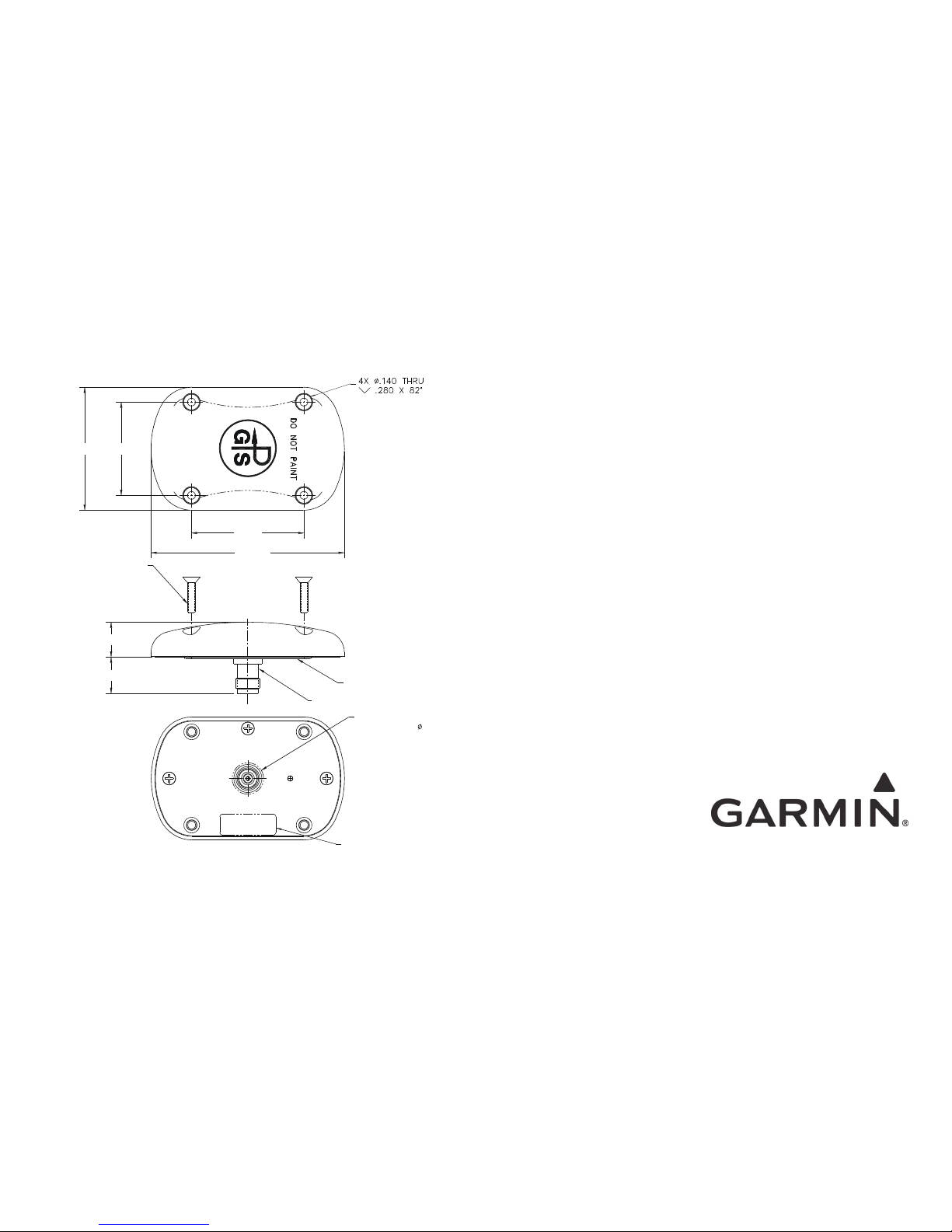
4X MOUNTING SCREW
6-32 UNC-2A
CROSS RECESSED
FLAT HEAD, SST
WIDTH
1.66
2.00
LENGTH
HEIGHT
.65
GASKET
TNCF CONNECTOR
CONNECTOR CLEARANCE
HOLE:
.63
TSO LABEL
Garmin A-33 and A33W
GPS Antenna
Installation Manual
August 2008
560-0949-01 Rev E
©2003 - 2008 by Garmin AT, Inc. Printed in the USA All Rights Reserved
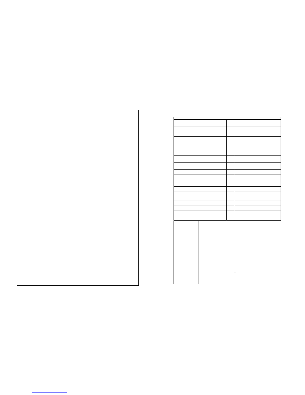
Environmental Qualifications
The A-33 and A33W antennas have been tested in the following environmental categories per
procedures defined in RTCA DO-160D.
Environmental Qualification Form
Nomenclature: Patch Antenna
Model No.: A-33 A33W
Part No.: 575-9 (590-1104) 575-33 2G (013- 00261-00 )
Manufacturer:
Aero Antenna Technology
Chatsworth, CA USA
Conditions Section Description of Conducted Tests
Temperature and Altitude
In-flight Loss of Cooling
4.0
4.5.4
Equipment tested to Category F2
No cooling required
Temperature Variation 5.0 Equipment tested to Category A
Humidity 6.0 Equipment tested to Category B severe humidity
environment, (more stringent than Category C)
Shock
Operational
Crash Safety
7.0
7.2
7.3
Equipment tested to Category B and D
Vibration 8.0 Equipment tested without shock mounts to
Categories S (Curves C, L, M, and Y) and
U (Curves F and F1)
Explosion Proofness 9.0 Equipment tested to Category E
Waterproofness 10.0 Equipment tested to Category S
(Also DO-160E Category Y)
Fluids Susceptibility 11.0 Equipment spray tested to Category F, with
Trichloroethane (cleaning solvent), and Ethylene
Glycol (de-icing fluid)
Sand and Dust 12.0 Equipment identified as Category D, Blowing sand
and dust (Also DO-160E Category S)
Fungus Resistance 13.0 Equipment tested to Category F, severe fungus
resistance
Salt Spray 14.0 Equipment tested to Category S, normal salt
atmosphere
Magnetic Effect 15.0 Equipment is Class Z
Power Input 16.0 E quipmen t tested t o Catego ry A. Antenna power
supplied directly from GPS receiver
Voltage Spike 17.0 Equipment tested to Category A. Antenna power
supplied directly from GPS receiver
Audio Frequency Conducted Susceptibility- Power Input 18.0 Equipment tested to Category Z. Antenna power
supplied directly from GPS receiver
Induced Signal Susceptibility 19.0 Equipment tested to Category Z and C
Radio Frequency Susceptibility 20.0 Equipment tested to Category YYP
Emission of Radio Freq. Energy 21.0 Equipment is Category H
Lightning Induced Transient Susceptibility 22.0 Equipment tested to Category A4ZZ
Lightning Direct Effects 23.0 Equipment tested to Category 2A.
Icing 24.0 Equipment tested to Category C with an ice
thickness of 0.50 inch.
Electrostatic Discharge 25.0 Equipment tested to Category A
Specifications A-33 Both A33W
Frequency: 1575 MHz ±10MHz
Polarization: Right Hand Circular
Axial Ratio: 3 dB Max at bore site
Radiation Coverage:
Elevation Angle: Minimum Gain Minimum Gain
>15º -2.0 dBic -2.0 dBic
10º -3.0 dBic -3.0 dBic
5° -4.5 dBic -3.5 dBic
0° -7.5 dBic -7.5 dBic
Weight: 3.9 oz. (0.11 kg) 7.5 oz. (0.22 kg)
Height: 0.62 inches (1.55 cm) 0.85 Inches (2.16 cm)
Length: 3.44 inches (8.74 cm) 3.80 inches (9.65 cm)
Width: 2.19 inches (5.57 cm) 2.97 inches (7.54 cm)
Finish: Polyurethane Enamel
Operating Temperature: 55°C to +85°C
Operating Altitude: 55,000 feet (16,764m) max
Amplifier:
Noise Figure: 2.5 dB Max
Impedance: 50 ohms
VSWR (Dry):
∠
1.5:1
VSWR (Rain):
∠
2.0:1
Band Rejection: 35 dB
Power Handling: 1 Watt
Voltage: 5 VDC ±10%
Current: 35 mA nom., 40 max 40 mA nominal, 60 max.
TSO: TSO-C144, C129a TSO-C144
1. Antenna Installation Considerations:
a. GPS signals are received by line of sight. The location chosen on the aircraft for placement of the
GPS antenna will have a lot to do with the overall performance of the GPS sensor. The antenna
MUST be located on the top of the aircraft. Typically, the best location is centerline as high and far
forward as possible, just aft the windscreen.
b. Any ‘shadowing’ or signal shading from the aircraft will degrade the performance of the GPS
receiver. Ideally, the antenna should have an unobstructed view of the sky from the horizon up.
However, some shading is inevitable in most installations.
c. Choose a location to minimize the length of coax. Shorter coax length provides better signal
strength available to the receiver.
d. Avoid locations that would subject the antenna to build up of contamination from exhaust.
e. Install the antenna symmetrically on the airframe. This is especially important on metallic aircraft,
as this affects the gain pattern of the antenna.
f. Select location to minimize effect from other antennas. Mount at least 2 feet from VHF Com
transmitter antennas, at least 6 inches from other antennas emitting less than 25 watts, and at
least 2 feet from higher power radio transmitting antennas. Follow installation spacing guidelines
from other near by antennas.
g. Installation on helicopters can present unique installation problems. When selecting antenna
placement, avoid exhaust areas, consider shadowing. One method to select antenna location is to
compare signal strength between various locations by temporarily attaching antenna to various
locations and compare signal strength. It is important to check with the rotors turning, as they can
be a source of shadowing.
2. Coax Cable Selection Considerations
a. Because of high frequency and sensitivity to cable losses, use high quality coax and coax
connectors, and minimize quantity of connectors and splices.
b. The type of coaxial cable may be dependent on the length required for installation. Long runs may
require lower loss cable to meet the cable loss requirements (see receiver install manual).
3. Installation Procedures:
a. Follow good avionics installation practices per FAA Advisory Circulars AC 43.13-1B, AC 43.13-2A,
and AC 20-138, or later FAA approved revisions of these documents.
b. Supplies required for installation, but not provided:
(4) #6 flat washer
(4) #6-32 locking nuts (may be part of doubler plate or backing plate)
Silicone sealer or other aviation type sealer
c. Provide a stable mounting base for the antenna and provide clearance for the connector. Use a
backing plate or doubler plate as required by the installation.
d. Insure a continuous contact between the antenna O ring seal and aircraft skin.
e. Use silicone sealer between the antenna and the aircraft skin. Use supplied four #6 stainless
screws to secure antenna to aircraft, using silicone sealer to seal the screws.
f. When routing the coax, avoid sharp bends, kinking or placement near aircraft control, power DME,
transponder or radio communications cables. Careful attention must be given when securing the
coax to the airframe. Do not allow cable ties to crimp or crush the coax.
g. Check the antenna installation using the GPS receiver to insure adequate signal strength. Refer to
GPS receiver installation manual.
4. Maintenance and Cleaning:
a. Occasionally clean and inspect the antenna. No other maintenance is required. Use mild detergent
and water to clean antenna. Never use abrasive materials or harsh chemicals.
b. Do not apply paint to the antenna.
c. Occasionally inspect the antenna to ensure that the installation remains well sealed against
moisture and the TNC connector remains free of corrosion.
d. If antenna should sustain damage, it cannot be repaired. Replace the antenna.
5. Limitations:
The conditions and test required for TSO approval of this article are minimum performance standards. It is
the responsibility of those desiring to install this article either on or within a specific type or class of aircraft
to determine that the article, when installed, performs in accordance with the design specifications that
meet this TSO. The article may be installed only if further evaluation by the applicant documents an
acceptable installation and is approved by the Administrator.
 Loading...