

Page 1
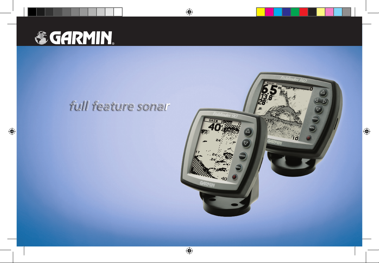
Fishfinder 90/140
full feature sonar
Owner’s Manual
190-00582-10_0A.indd 1 12/2/2011 3:08:54 PM
Page 2
© 2008 Garmin Ltd. or its subsidiaries
Garmin International, Inc.
1200 East 151st Street,
Olathe, Kansas 66062, USA
Tel. (913) 397.8200 or (800) 800.1020
Fax (913) 397.8282
Garmin (Europe) Ltd.
Liberty House
Hounsdown Business Park,
Southampton, Hampshire, SO40 9RB UK
Tel. +44 (0) 870.8501241 (outside the UK)
Garmin Corporation
No. 68, Jangshu 2nd Road,
Shijr, Taipei County, Taiwan
Tel. 886/2.2642.9199
Fax 886/2.2642.9099
0808 2380000 (within the UK)
Fax +44 (0) 870.8501251
All rights reserved. Except as expressly provided herein, no part of this manual may be reproduced, copied, transmitted, disseminated, downloaded or
stored in any storage medium, for any purpose without the express prior written consent of Garmin. Garmin hereby grants permission to download a
single copy of this manual onto a hard drive or other electronic storage medium to be viewed and to print one copy of this manual or of any revision
hereto, provided that such electronic or printed copy of this manual must contain the complete text of this copyright notice and provided further that any
unauthorized commercial distribution of this manual or any revision hereto is strictly prohibited.
Information in this document is subject to change without notice. Garmin reserves the right to change or improve its products and to make changes in
the content without obligation to notify any person or organization of such changes or improvements. Visit the Garmin Web site (www.garmin.com) for
current updates and supplemental information concerning the use and operation of this and other Garmin products.
Garmin® is a trademark of Garmin Ltd. or its subsidiaries, registered in the USA and other countries. This trademark may not be used without the
express permission of Garmin.
December 2008 Part Number 190-00582-10 Rev. A Printed in Taiwan
190-00582-10_0A.indd 2 12/2/2011 3:08:54 PM
Page 3
Introduction
Introduction
This manual covers the features and operation of the
Fishnder 90/140.
About This Manual
To get the most out of your Fishnder 90/140, take time to
read this manual and learn the operating procedures for your
unit in detail. This manual is organized into the following
sections.
The Introduction sections contains the Table of Contents,
Product Registration, and Product Support Information.
The Getting Started sections contain information about
sonar and the Fishnder.
The Installing Your Fishnder section provides instruction
on installing the Fishnder and the Transducer. If you
experience difculty installing the Fishnder, contact
Garmin Product Support or an installation professional in
your area.
Fishnder 90/140 Owner’s Manual iii
The Operating Your Fishnder section describes the
features and operation of the Fishnder 90/140.
The Appendix contains unit specications ,optional
accessories, and care information. You can also nd
warranty information, the Software License Agreement and
European Licensing Requirements in the Appendix.
An Index is provided at the end of the manual for reference.
Manual Conventions
This manual uses the term Warning to indicate a potentially
hazardous situation, which, if not avoided, could result in
death or serious injury.
This manual uses the term Caution to indicate a potentially
hazardous situation, which, if not avoided, may result
in minor injury or property damage. It may also be used
without the symbol to alert you to avoid unsafe practices.
190-00582-10_0A.indd 3 12/2/2011 3:08:54 PM
Page 4
Introduction
Table of Contents
Introduction ............................................................. iii
About This Manual ...........................................................iii
Manual Conventions ........................................................iii
Product Registration ........................................................ v
Contact Garmin ................................................................ v
Warning ........................................................................... vi
Getting Started ......................................................... 1
Understanding the Fishnder ...........................................1
Using Simulator Mode ...................................................... 4
Appendix ................................................................ 19
Specications .................................................................19
Optional Accessories .....................................................19
Caring for the Fishnder ................................................19
Software License Agreement .........................................21
Limited Warranty ............................................................21
Declaration of Conformity (DoC) ....................................23
Index ....................................................................... 24
Installing Your Fishnder ....................................... 5
Installing the Transducer .................................................. 6
Installing the Fishnder Unit ........................................... 10
Installing the Wiring Harness .........................................12
Testing the Transom Mount Installation .........................13
Operating Your Fishnder .................................... 14
Understanding Basic Functions .....................................14
Using the Main Menu ..................................................... 15
Using the Setup Menu ...................................................16
iv Fishnder 90/140 Owner’s Manual
190-00582-10_0A.indd 4 12/2/2011 3:08:55 PM
Page 5
Introduction
Product Registration
Help us better support you by completing our online
registration today. Go to http://my.garmin.com. Keep the
original sales receipt, or a photocopy, in a safe place.
Contact Garmin
Contact Garmin Product Support if you have any questions
while using your Fishnder 90/140. In the USA, go to
www.garmin.com/support, or contact Garmin USA by
phone at (913) 397.8200 or (800) 800.1020.
In the UK, contact Garmin (Europe) Ltd. by phone at 0808
2380000.
In Europe, go to www.garmin.com/support and click
Contact Support for in-country support information,
or contact Garmin (Europe) Ltd. by phone at +44 (0)
870.8501241.
Fishnder 90/140 Owner’s Manual v
190-00582-10_0A.indd 5 12/2/2011 3:08:55 PM
Page 6
Introduction
Warning
Failure to avoid the following potentially hazardous situations could result in an accident or collision resulting in death or serious
injury.
When navigating, carefully compare information displayed on the Fishnder 90/140 to all available navigation sources, including information
from visual sightings, and maps. For safety, always resolve any discrepancies or questions before continuing navigation.
vi Fishnder 90/140 Owner’s Manual
190-00582-10_0A.indd 6 12/2/2011 3:08:55 PM
Page 7
Getting Started
Getting Started
To get the most out of your new Fishnder:
• Before you install and use your Fishnder, read the
information in this manual.
• Assemble and install the hardware (page 5).
• Practice using your Fishnder in Simulator Mode
(page 4).
• Use the Fishnder (page 14).
Understanding the Fishnder
The Fishnder 90 or 140 is a fully automatic sonar unit
that allows you to go out on the water and nd sh without
having to congure a lot of settings; or, if from experience
you know exactly how you want your Fishnder screen to
look and function, you can customize each setting to your
specic needs.
If you have used a Fishnder before, and you know how
to interpret the sonar information on the screen, you can
skip this section. If you have not used a Fishnder before,
Fishnder 90/140 Owner’s Manual 1
you might want to learn a bit about sonar: what it is, how it
works, and what you might see on the Fishnder 90 or 140
screen. This manual does not go into technical detail about
sonar, but it can give you a general understanding of those
things that you need to know about sonar that can help you
interpret the screen and nd the sh.
Understanding Sonar
During installation, you connect your Fishnder 90 or 140
to a transducer. The transducer uses sound to determine
information about what is in the water beneath your boat.
Then the transducer sends the information to your Fishnder
to be displayed on the screen for you to view and interpret.
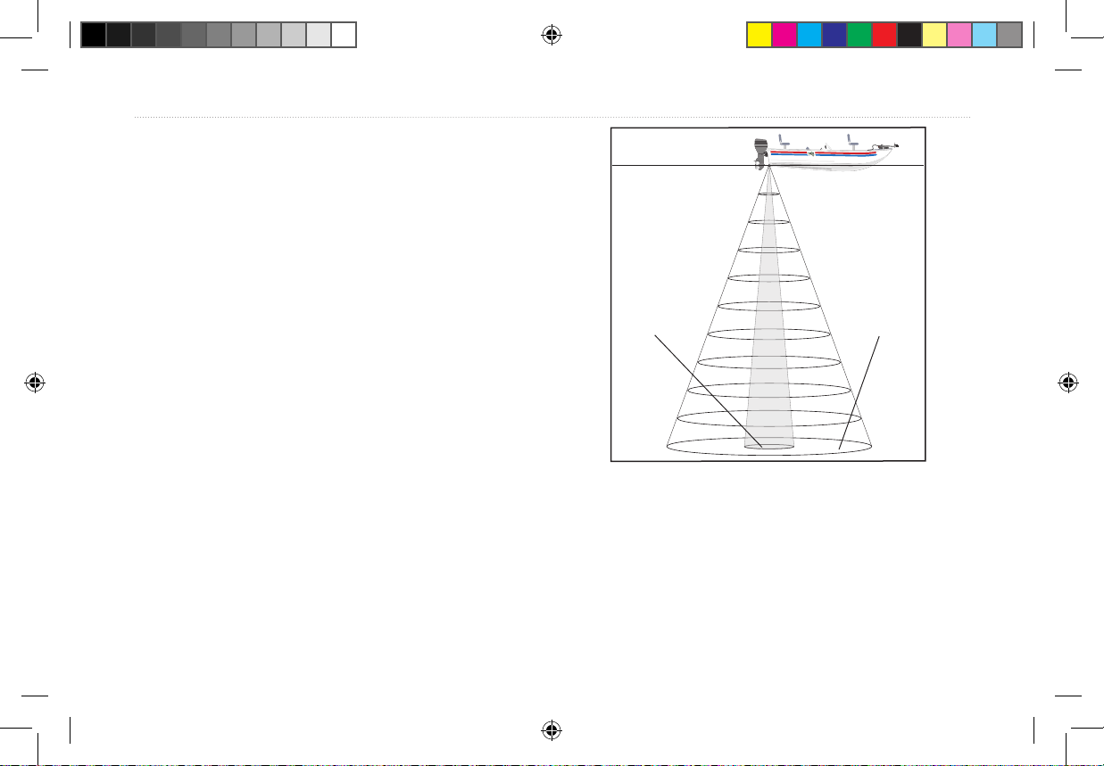
The transducer sends sound waves down into the water
in a cone shape, similar to a ashlight beam (covering a
smaller circular area at the top and angling out to a larger
circular area at the bottom). These sound waves reect off
of any object that they hit, and then the waves travel back
up to the transducer. These objects could be sh, branches,
the bottom, or any other object that has density that is
different from the water. The transducer receives the sound
190-00582-10_0A.indd 1 12/2/2011 3:08:55 PM
Page 8
Getting Started
wave information, and then sends the information to the
Fishnder. The Fishnder displays the information on the
screen for you to see and interpret. The type of transducer
and settings you choose determine how the information is
shown on the screen.
Understanding Dual Beam Transducer
Coverage
A dual beam transducer can transmit a narrow or a wide
beam. The water area covered by the transmitted sound
waves is determined by the beam width of the transducer
and the water depth. The narrow beam provides crisp detail
of what is under your boat, and is helpful if you are shing
in deeper water where the beam covers more area (for
example, at a 30-foot depth, the narrow beam covers the
area of about a 7-foot circle).
The wide beam is more helpful in shallow water, because
it gives you a much wider view of objects in the water,
including areas beyond the sides of your boat. At a 30-foot
depth, the wide beam covers the area of approximately a
20-foot circle.
Narrow
Beam
Wide
Beam
2 Fishnder 90/140 Owner’s Manual
190-00582-10_0A.indd 2 12/2/2011 3:08:55 PM
Page 9
Getting Started
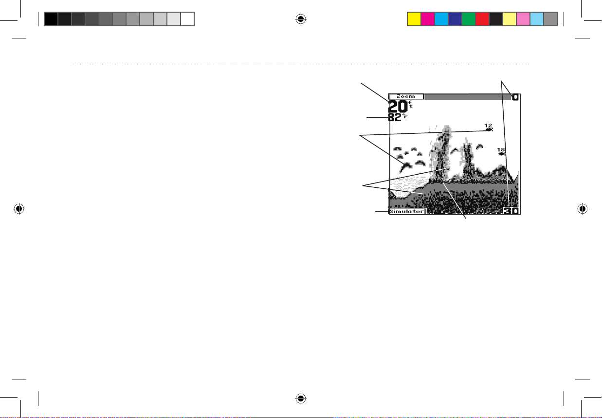
Understanding the Fishnder Screen
Experimentation and experience are the keys to successfully
interpreting your Fishnder screen. We recommend that you
take your Fishnder out on familiar water, and spend time
learning to interpret what you see on the Fishnder 90 or
140 screen.
Think of the Fishnder screen as if you took a picture
from the side of an aquarium in your home. You can see
how deep a sh is in the water (how close it is to the top
or bottom), but you cannot tell where the sh is located
horizontally in the water (whether it is near the front or the
back of the aquarium). Remember this when you are trying
Water
temperature at
the transducer
suspended targets
as arches or sh
Water depth
You see
symbols.
Structure
Simulator
mode
indicator
Bottom shape and type
Depth range
to locate exactly where something is in the water.
The strongest sonar returns appear on your screen as solid,
dark areas. The weakest returns appear less intense, less
solid. The bottom of the water body returns the strongest
signal, so you can identify the bottom as the continuous,
solid line running across the bottom of the screen. The
strength of the sonar return can also help you interpret the
hardness of the bottom. The thicker the bottom line, the
harder the bottom.
Fishnder 90/140 Owner’s Manual 3
190-00582-10_0A.indd 3 12/2/2011 3:08:55 PM
Page 10
Getting Started
The Fishnder 90 and 140 include the latest technology
instead of arches (page 17).
in interpreting bottom signals; they can see through sh,
structures, and thermoclines (shown in the weakest hues).
Even so, large schools of sh or dense structures close to
the bottom can affect water depth return readings.
NOTE: If the Fishnder is unable to track the bottom for
any reason, the digits which indicate depth ash on and off
to alert you that the Fishnder is not tracking the bottom.
Along the top of the screen, you might see a grouping of
intense hues. This area is surface clutter, which can be
caused by waves or any other sonar interference at the
surface of the water. Too much surface clutter can obscure
your view of sh. You can turn down the Gain setting to
Using Simulator Mode
Use Simulator Mode to practice and learn the operation of
the Fishnder. If the Fishnder does not detect a transducer
at startup, it automatically starts in Simulator Mode.
While in Simulator Mode, the Fishnder displays a bottom
scene, and you can control the Fishnder (except the Gain
and Auto Gain options) just as if it were on the water.
If no keys are pressed for two minutes, the Fishnder
automatically resets to default settings while in Simulator
Mode.
To exit Simulator Mode, turn off the Fishnder.
reduce this surface clutter (page 15).
You can see in the previous illustration how the sh are
indicated in a few different ways. By default, sh appear
as arches. Actual sh returns might not always appear as
perfect arches, due to the speed, sh orientation, or other
conditions. You can also turn on the Fish Symbols setting if
you want to see suspended targets indicated by a sh shape
4 Fishnder 90/140 Owner’s Manual
190-00582-10_0A.indd 4 12/2/2011 3:08:55 PM
Page 11
Installing Your Fishnder
A
Make sure you completely read and understand all
instructions before you install and use your Fishnder. If
you have problems, contact Garmin Product Support, or
seek other professional assistance.
You can install the Fishnder hardware on a transom or on
a trolling motor. Before installation, make sure the wiring
(Fishnder 90)
harness can reach the Fishnder and transducer locations.
Check the packing list below. If you are missing any items,
contact your Garmin dealer.
Installing Your Fishnder
E
F
B1
(Fishnder 140)
C
G
(Fishnder 90)
D
B2
S
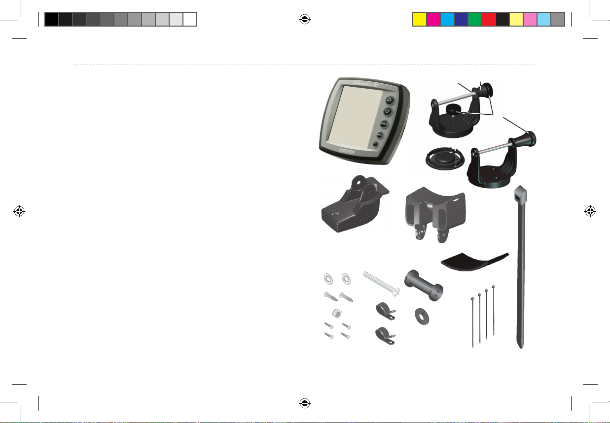
Packing List (one of each, unless otherwise noted):
A—Fishnder sonar unit
B1—Swivel mount bracket (Fishnder
140; optional for Fishnder 90); or
B2—Tilt mount bracket (Fishnder 90)
C—Swivel base (Fishnder 140)
D—Mounting knobs
E—Mounting knob spacer
F—Snap ring
G—Transducer with power cable
H—Transducer mount
Fishnder 90/140 Owner’s Manual 5
190-00582-10_0A.indd 5 12/2/2011 3:08:57 PM
I—Trolling motor mount gasket
J—5 mm Flat washers (2)
K—5 x 30 mm Screws (2)
L—10-32 Lock nut
M—4 x 12 mm Screws (4)
N—10-32 x 1.75 Screw
O—1/4" Cable clamps (2)
P—Plastic spacer
Q—1/4" Rubber washer
R—Cable tie, 5.6" (4)
S—Cable tie, 20”
(Cable not shown)
J
K
L
M
N
O
H
I
P
R
Q
Page 12
Installing Your Fishnder
Installing the Transducer
Assembling the Transducer
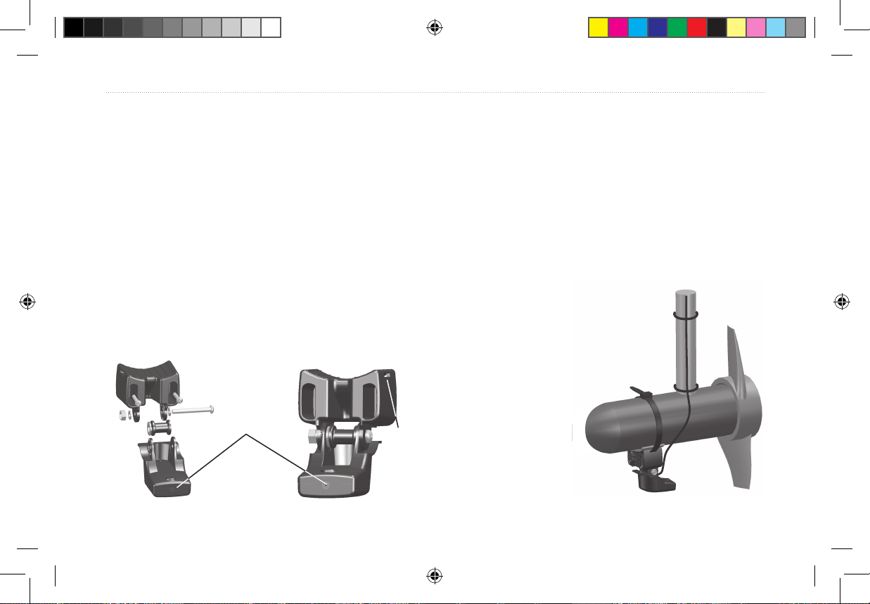
1. Insert the rubber washer (Q) and plastic spacer (P) into
the transducer (G) at the same time. DO NOT lubricate
the rubber washer.
2. Route the cable toward the back of the transducer. Slide
the transducer into the transducer mount (H).
3. Place a 5 mm at washer (J) on the 10-32 x 1.75" screw
(N), and insert the screw through the transducer mount,
spacer, and rubber washer.
4. Place the remaining 5 mm at washer on the exposed
end. Install the 10-32 lock nut (L) nger tight. You can
Mounting the Transducer on a
Trolling Motor
1. Slide the large cable tie (S) through the slot on the
transducer mount (H) with the ridges of the band facing
up until equal lengths extend on both sides of the mount.
(NOTE: For cold water, or heavy timber or debris areas,
a metal 4-5" worm gear clamp is recommended.)
2. Position the mount gasket (I) on the curved top of the
transducer mount.
3. Place the transducer assembly against the motor body of
the trolling motor, with the front of the
transducer pointed away from the
trolling motor propeller.
tighten the transducer further after installation on the
boat.
Back of the transducer
6 Fishnder 90/140 Owner’s Manual
Cable tie
slot
190-00582-10_0A.indd 6 12/2/2011 3:08:57 PM
Page 13
Installing Your Fishnder
4. Wrap the two ends of the cable tie around the motor
body. Place the pointed end of the cable tie through the
fastener hole on the opposite end and pull it through until
it is snug but not tight. (The cable tie clicks when you pull
it.)
5. Position the transducer so that it is parallel with the
bottom when in use, and make sure the gasket is aligned
properly. Pull the cable tie end until tight. Trim off the
excess, if necessary. Tighten the 10-32 locking nut until
it touches the mounting bracket and then tighten 1/4 turn
more. (Do not overtighten.)
6. Route the 20’ (6 m) transducer cable using the supplied
cable ties to secure the cable to the motor shaft. You
can ll the forward-facing portion (except the cable tie
pocket) of the transducer mount with sealant to avoid
accumulating debris.
Mounting the Transducer on a Transom
Tool List (not included)—drill, 3/8" wrench or socket,
5/32" and 1/8" drill bits, masking tape, #2 Phillips
screwdriver, and marine sealant.
When selecting a transom mount location, consider the
following for optimal performance:
• For your sonar to operate properly, the transducer must
be located in calm water. DO NOT mount the transducer
behind strakes, rivet lines, struts, ttings, water intake,
discharge ports, eroding paint, or anything that creates
turbulence.
• Mount the transducer as close to the center of the boat as
possible.
• DO NOT cut the transducer lead. (This voids your
warranty.)
• DO NOT mount the transducer in locations where it
might be jarred when launching, hauling, trailering, or
storage.
Fishnder 90/140 Owner’s Manual 7
190-00582-10_0A.indd 7 12/2/2011 3:08:57 PM
Page 14
Installing Your Fishnder
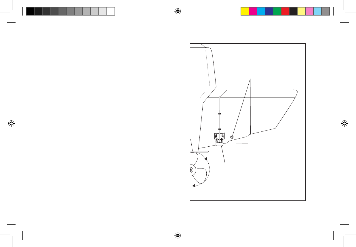
• DO NOT mount the transducer in the path of the prop on
single-drive boats. The transducer can cause cavitation
that can degrade the boat’s performance and damage the
prop. On twin-drive boats, mount the transducer between
the drives, if possible.
Do not mount the transducer behind
strakes, rivet lines, struts, ttings, water
intakes or discharge ports.
Mount the transducer
parallel with the water line.
Make sure the transducer is below
water level when the boat is on plane
at high speed.
Apply marine sealant to all screw threads to prevent
water from seeping into the transom.
8 Fishnder 90/140 Owner’s Manual
190-00582-10_0A.indd 8 12/2/2011 3:08:58 PM
Page 15
Installing Your Fishnder
To mount the transducer on a transom:
1. Position the transducer mount at the selected transom
location. Make sure the transducer is parallel with the
water line. Mark the center locations of each hole on the
transducer mount. (See the gures on the next page.)
2. Using a 5/32" bit, drill the pilot holes approximately 1"
(25 mm) deep at the marked locations. To avoid drilling
the holes too deep, wrap a piece of tape around the bit
at 1" from the point of the bit.
3. Apply marine sealant to the 5 x 30 mm screws. Attach
the transducer assembly to the transom using the 5 x 30
5. Place the rst cable clamp on the transducer cable
approximately one third of the distance between the
transducer and the top of the transom. Mark the location.
Using a 1/8" bit, drill a pilot hole approximately 3/8" (10
mm) deep.
6. Attach the cable clamp using a 4 x 12 mm screw. Coat
the screw with marine sealant before installation. Repeat
steps 5 and 6 using the other cable clamp.
7. Route the transducer cable, as needed, to the Fishnder.
DO NOT CUT THE CABLE. Avoid routing the cable with
electrical wires or other sources of electrical interference.
mm screws. Adjust the transducer assembly to extend
beyond the bottom of the transom approximately 1/8"
(3 mm) on berglass hulls or 3/8" (10 mm) on aluminum
hulls. Adjust the transducer assembly to be aligned
parallel with the water.
4. Tighten the 10-32 locking nut until it touches the
mounting bracket, and then tighten 1/4 turn more. (Do
not overtighten.)
Fishnder 90/140 Owner’s Manual 9
190-00582-10_0A.indd 9 12/2/2011 3:08:58 PM
Page 16
Installing Your Fishnder
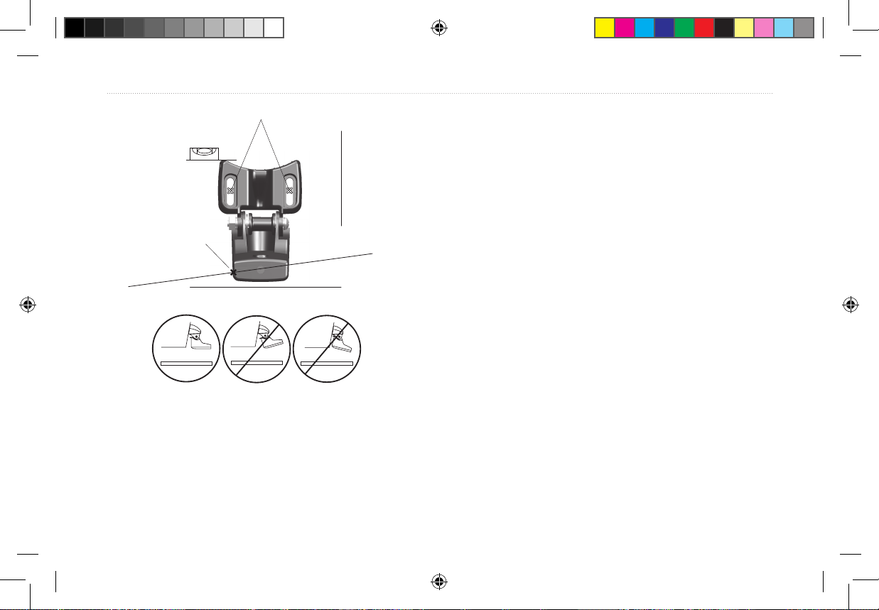
Drill pilot holes here.
Level
Installing the Fishnder Unit
Selecting a Fishnder installation Location
Select a Fishnder installation location that allows you to
Align with the
transom bottom. The
transducer should
extend 1/8" below
berglass hulls or
3/8" below aluminum
hulls.
Keep it parallel with the water line.
OK
Vertical
Bottom of the transom
view and operate it easily while operating the vessel. Select
a mounting surface strong enough to support the weight
of the Fishnder and protect it from excessive vibration or
shock. DO NOT mount the bracket in a location where the
Fishnder is exposed to extreme temperature conditions.
When installing the mounting bracket, be sure to allow
room to connect and rout the power cable.
Mounting the Bracket Assembly
Tool List (not included)—drill, screwdriver (Phillips or
standard), three #8 pan-head machine bolts with matching
nuts and washers, and a 5/32" drill bit; or three #8 pan-head,
self-tapping screws and a 1/16" drill bit.
10 Fishnder 90/140 Owner’s Manual
190-00582-10_0A.indd 10 12/2/2011 3:08:58 PM
Page 17
Installing Your Fishnder
To mount the bracket assembly:
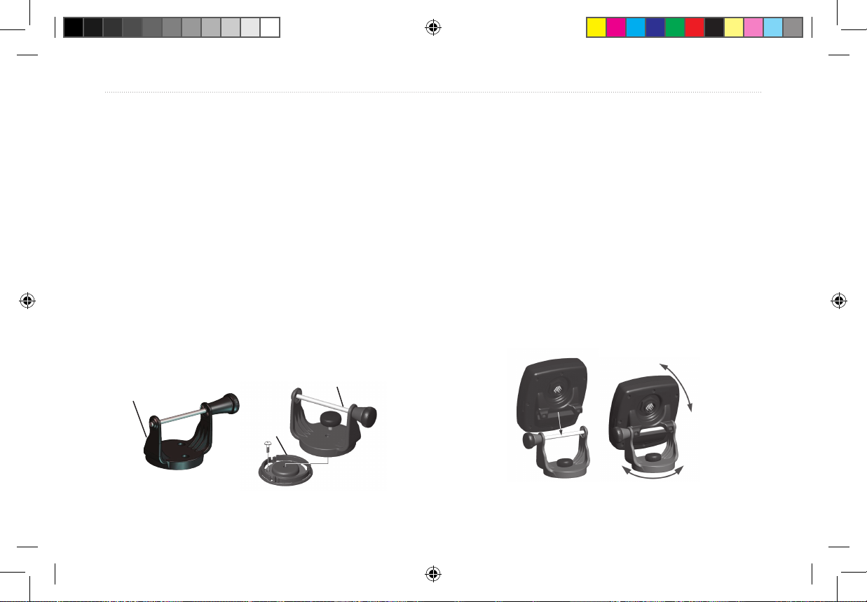
1. Using the tilt mount bracket (Fishnder 90) or the
swivel base (Fishnder 140; Fishnder 90 option) as a
template, mark the location of the three holes that you
use to secure the bracket to the mounting surface.
2. If securing the base with machine bolts, drill three 5/32"
holes at the locations you marked; or, if securing the
base using self-tapping screws, drill 1/16" starter holes
at the locations you marked. Drill starter holes no deeper
than half the screw length.
3. Secure the tilt mount bracket or swivel base with three
bolts or screws. DO NOT OVERTIGHTEN.
To install the Fishnder on the mount bracket:
1. Align the slot on the back of the Fishnder with the long
mounting knob, and slide the Fishnder into place. If
necessary, adjust the long knob to spread the bracket
arms apart. (Turn counter-clockwise to widen the bracket
arms and clockwise to tighten.)
2. Adjust the Fishnder angle, and tighten the long
mounting knob until snug.
3. For the Fishnder 140 (Fishnder 90 option), rotate
the swivel mount bracket by twisting it left or right. The
bracket clicks as you turn it. Select a good viewing
angle, and then tighten all knobs.
4. If you are using the swivel mount, place the swivel mount
bracket over the swivel base and secure it with the short
knob.
Swivel mount bracket
Tilt mount bracket
Swivel base
(Fishnder 90)
Fishnder 90/140 Owner’s Manual 11
(Fishnder 140;
Fishnder 90 option)
190-00582-10_0A.indd 11 12/2/2011 3:08:58 PM
Page 18
Installing Your Fishnder
Installing the Wiring Harness
The Fishnder comes with a wiring harness that connects
the Fishnder to power and the transducer with one
easy-to-remove connection. If it is necessary to extend the
power wires, use 22 AWG wire. DO NOT cut the transducer
cable, because this voids your warranty. If your boat has an
3. Install the black (-) wire on the negative fuse holder or
battery terminal.
4. Install a 2 Amp fuse in the fuse holder (fuse block only).
5. Align the notches on the cable plug and on the back of
the Fishnder. Insert the cable into the connector and
turn the lock ring counter-clockwise until it stops.
electrical system, you might be able to wire the Fishnder
directly to an unused holder on your current fuse block. If
you are using the boat’s fuse block, remove the in-line fuse
holder supplied with the Fishnder. You can also wire the
Fishnder directly to the battery.
CAUTION: The Fishnder input voltage is 10–18 volts
DC. Do not exceed this voltage, because this can damage
the Fishnder and void the warranty.
To install the wiring harness:
1. Determine the polarity of the power source using a test
light or volt meter.
2. Install the red (+) wire on the positive fuse holder or
battery terminal.
12 Fishnder 90/140 Owner’s Manual
190-00582-10_0A.indd 12 12/2/2011 3:08:58 PM
Page 19
Installing Your Fishnder
Testing the Transom Mount Installation
Perform this test after you install the Fishnder. Because
you need water to carry the sonar signal, the Fishnder
does not function properly with the transducer out of the
water. When you place your boat in the water, CHECK FOR
LEAKS around the screw holes that are below the water
line. DO NOT leave your boat in the water for an extended
period of time without checking for leaks.
Fishnder 90/140 Owner’s Manual 13
To test the transom mount installation:
1. Begin testing the installation at a slow speed. If the
sonar appears to be working properly gradually increase
the boat’s speed observing the sonar’s operation. If
the sonar signal suddenly is lost or the bottom return is
severely degraded, note the speed at which this occurs.
2. Return the boat to the speed at which the signal was
lost. Make moderate turns in both directions, and see if
the signal improves.
3. If the signal strength improves while turning, adjust the
transducer so that it extends another 1/8" below the
transom of the boat. It might take several adjustments to
eliminate the degradation.
4. If the signal does not improve, it might be necessary to
move the transducer to a different location.
190-00582-10_0A.indd 13 12/2/2011 3:08:58 PM
Page 20
Operating Your Fishnder
Operating Your Fishnder
Understanding Basic Functions
To turn on the Fishnder:
Press and release the Power key.
To turn off the Fishnder:
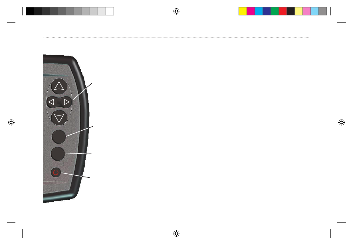
Arrow keys—the up and down Arrow
keys select an item on a menu. Only
the Fishnder 140 has the right and left
Arrow key that cycles through the Main
menu options.
Press and hold the Power key.
To change the backlight level:
Press the Power key repeatedly to cycle between off,
low, and high.
To view or change settings for your Fishnder, use the Main
menu and the Setup menu.
ENTER key—conrms a selection.
ENTER
MENU
14 Fishnder 90/140 Owner’s Manual
MENU key—shows or exits a menu.
Power key—turns the Fishnder on or
off and controls the screen backlight.
(Fishnder 140 is shown.)
To change a setting:
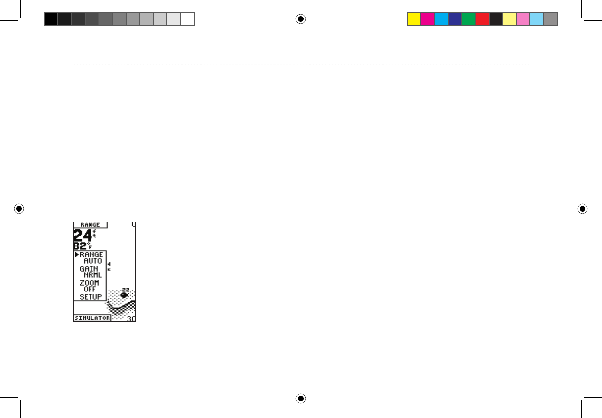
1. Press MENU. The Main menu appears.
2. Use the Arrow keys to move the selection arrow to an
option, and press ENTER. The settings appear.
If you select Setup, the Setup menu appears. See
“Using the Setup Menu” on page 16.
190-00582-10_0A.indd 14 12/2/2011 3:08:59 PM
Page 21
Operating Your Fishnder
3. To select a setting, use the Arrow keys to move the
selection arrow, and press ENTER. (When you reach
the end of a menu, the selection arrow wraps to the
beginning.) Press and hold an Arrow key to rapidly
advance the selection speed.
4. To close a setting or a menu, press MENU.
• To quickly change a setting for the current option
that appears in the upper-left corner of the screen (for
example, the Range option in the above screen), press an
Arrow key.
Options and Settings
The following settings reset to the system defaults each time
Using the Main Menu
From the Main menu, you can change the Range, Gain,
Scroll, Zoom, and View settings.
• To view the current menu settings, press MENU.
you turn on the Fishnder.
Range—sets the maximum depth that you want the
Fishnder to display. Auto (default) automatically tracks
the bottom, or you can set the range, 5–600 feet.
Gain—controls the sensitivity of the Fishnder’s sonar
receiver. Auto (default) automatically sets the sonar
sensitivity, or you can set the gain. To see more detail on the
screen, increase the receiver sensitivity by selecting a higher
gain. If there is too much detail or if the screen is cluttered,
lower the sensitivity (lower the gain) to increase the clarity
of the screen.
• To exit any window, press MENU.
Fishnder 90/140 Owner’s Manual 15
190-00582-10_0A.indd 15 12/2/2011 3:08:59 PM
Page 22
Operating Your Fishnder
Scroll—sets the rate that the graph scrolls from right to
left. If you are sitting still or the graph is moving too fast,
slowing or pausing the graph can help. The settings are
Ultra, Fast (default), Medium, Slow, and Paused.
Zoom—sets the zoom level for the screen. Off is the
default.
View—when you select a 2X or 4X Zoom setting, you
can select a specic area to view on the screen. You can
also allow the Fishnder to automatically select a zoomed
viewing area based on the bottom.
Using the Setup Menu
To access the Setup menu:
Press MENU. Use the Arrow keys to move the selection arrow to Setup, and
press ENTER. The options appear.
Options and Settings
Your changes to the following settings are used until you
set the System Defaults option to Yes.
Alarms
Battery—controls an alarm that sounds when the battery is
reaching a critical state of discharge. The settings are
Off (default) and 8.5–16.0 volts remaining.
Shallow—sets an alarm for a shallow water warning at a
specic depth. The settings are Off (default) and 1.0–600
feet.
Deep—sets an alarm for a deep water warning at a specic
depth. The settings are Off (default) and 1.0–600 feet.
Fish—turns on or off (default) an alarm that sounds when
the Fishnder detects what it determines to be a sh.
16 Fishnder 90/140 Owner’s Manual
190-00582-10_0A.indd 16 12/2/2011 3:08:59 PM
Page 23
Operating Your Fishnder
Graphs
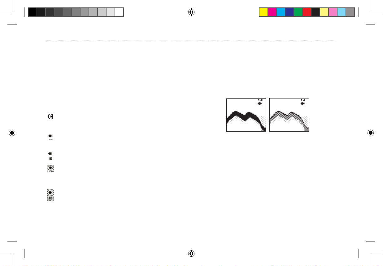
Fish ID—sets how the Fishnder shows underwater
targets and background information. If you select a
sh symbol, the screen shows only the information
the sides of the boat. You can also choose Narrow (default)
beam.
Whiteline—sets how the Fishnder shows information
about the bottom type.
related to that symbol (large, medium, and small sizes).
When using wide beam, sh symbols that are to the
• Off—the bottom return appears as solid black.
sides of the boat appear hollow. Those that are directly
below the boat appear as solid black sh symbols.
(default) the Fishnder does not interpret the sonar
return data. Fish appear as arches
Suspended targets appear as symbols. No background
information appears
Same as previous with the target depth shown.
Suspended targets appear as symbols. Background
information appears, making the distinction between
Whiteline Off
• On (default)—the bottom return appears as a grayscale
pattern and can help to determine bottom hardness.
A hard bottom displays a thicker bottom layer. A soft
bottom appears as a thinner bottom layer.
Whiteline On
sh and structure easier.
Same as previous with target depth shown.
Beam—controls the angle of the transducer beam. Wide
beam allows you to see more sh in shallow water, even off
Fishnder 90/140 Owner’s Manual 17
190-00582-10_0A.indd 17 12/2/2011 3:08:59 PM
Page 24
Operating Your Fishnder
Auto Gain—controls the aggressiveness of the Auto Gain.
The higher the setting, the greater the number of targets
appear on the screen. The lower the setting, the less clutter
on the screen. The settings are High, Medium (default), and
Low.
Numbers
Size—sets the appearance of depth, temperature, and battery
numbers. The settings are Small and Large (default).
Battery—sets whether the current battery voltage appears
on the screen. The settings are Hide (default) and Show
Water Temperature—sets whether the water temperature
appears on the screen. This appears only if you have a
temperature-capable transducer. The settings are Hide and
Auto (default).
Units
Depth—sets the measurements in Feet (default), Meters, or
Fathoms.
Temperature—sets the water temperature units. The
settings are Fahrenheit (default) and Celsius.
System
Simulator—controls the simulator mode. The settings are
Off and On (default). See page 4 for more information.
Language—sets your language choice.
Beeper—controls all Fishnder sounds. The settings are
Off and On (default).
Contrast—adjusts the contrast of the screen to compensate
for light levels or viewing angles. Use the Arrow keys to
increase or decrease the screen contrast.
Defaults—restores all default settings.
18 Fishnder 90/140 Owner’s Manual
190-00582-10_0A.indd 18 12/2/2011 3:08:59 PM
Page 25
Appendix
Appendix
Specications
Fishnder 90
Size: 4.7" W x 4.9" H x 2.43" D (11.9 x 12.4 x 6.1 cm)
Weight: 15.5 oz (.439 kg)
Display: 2.0" W x 3.3" H (5.0 x 8.4 cm), 3.9" (9.9 cm) diagonal,
64 x 128 pixels, black-and-white FSTN display
Usage: 3.5 watts maximum, Nominal: 12 VDC @ 0.15 Amps
Fishnder 140
Size: 6.1" W x 4.9" H x 2.6" D (15.5 x 12.5 x 6.6 cm)
Weight: 18.7 oz. (.530 kg)
Display: 3.2" W x 3.1" H (8.1 x 7.9 cm), 4.7" (9.9 cm) diagonal,
128 x 240 pixels, 4-level gray scale FSTN display
Usage: 8 watts maximum, Nominal: 12 VDC @ 0.5 Amps
Fishnder 90 and Fishnder 140
Case: Fully Gasketed, high-impact plastic alloy Waterproof: IEC 529,
level IPX-7 (submerged to 1 meter for 30 minutes)
Temperature Range: +5°F to 158°F (-15°C to 70°C)
Internal memory backup to retain user settings
Fishnder 90/140 Owner’s Manual 19
Input: 10 to 18 VDC with high voltage protection
Sonar Power Output: 100 watts (RMS), 800 watts (peak-to-peak)
Frequency: 80 kHz (wide) and 200 kHz (narrow)
Depth: 600 foot max depth. (Depth capacity is dependent on water
salinity, bottom type, and other water conditions.)
Specications are subject to change without notice.
Optional Accessories
Purchase the following optional accessories on the Garmin Web site:
Swivel mount for the Fishnder 90—allows your Fishnder 90 to tilt
and swivel on its mounting bracket.
Portable case with battery pack and suction mount transducer—
makes your Fishnder portable, so that it can go on any boat, with no
installation (requires eight D-cell batteries, not included).
Flush mounting kit—mounts your shnder ush on the bulkhead or
cabin wall. Press the side clips to release the Fishnder so you can take it
with you.
Protective cover—protects your product when you are not using it.
Caring for the Fishnder
The Fishnder case is constructed of high quality materials
and does not require user maintenance except cleaning.
190-00582-10_0A.indd 19 12/2/2011 3:08:59 PM
Page 26
Appendix
Cleaning the Case
Clean the Fishnder’s outer casing (except for the screen)
using a cloth dampened with a mild detergent solution, and
then wipe it dry. Avoid chemical cleaners and solvents that
may damage plastic components.
WARNING: The Fishnder screen is coated with a special
anti-reective coating which is very sensitive to skin oils,
waxes, and abrasive cleaners. CLEANERS CONTAINING
AMMONIA WILL HARM THE ANTI-REFLECTIVE
COATING. It is very important to clean the screen using
an eyeglass lens cleaner which is specied as safe for antireective coatings and a clean, lint-free cloth.
Cleaning the Screen
The Fishnder screen should be cleaned using a soft, clean,
lint-free cloth. Water or eyeglass cleaner can be used if
needed. If these are used, apply the liquid to the cloth and
then gently wipe the screen with the moistened cloth.
Storage
Do not store the Fishnder where prolonged exposure to
temperature extremes may occur (such as in the trunk of a
car), because permanent damage may result.
Water Immersion
The Fishnder is waterproof to IEC Standard 60529 IPX7.
It can withstand immersion in 1 meter of water for 30
minutes. Prolonged submersion can cause damage to the
Fishnder. After submersion, be certain to wipe and air dry
the Fishnder before reuse.
20 Fishnder 90/140 Owner’s Manual
190-00582-10_0A.indd 20 12/2/2011 3:08:59 PM
Page 27
Appendix
Software License Agreement
BY USING THE FISHFINDER YOU AGREE TO BE BOUND BY THE
TERMS AND CONDITIONS OF THE FOLLOWING SOFTWARE
LICENSE AGREEMENT. PLEASE READ THIS AGREEMENT
CAREFULLY.
Garmin grants you a limited license to use the software embedded in
this device (the “Software”) in binary executable form in the normal
operation of the product. Title, ownership rights, and intellectual property
rights in and to the Software remain in Garmin.
You acknowledge that the Software is the property of Garmin and
is protected under the United States of America copyright laws and
international copyright treaties. You further acknowledge that the
structure, organization, and code of the Software are valuable trade
secrets of Garmin and that the Software in source code form remains a
valuable trade secret of Garmin. You agree not to decompile, disassemble,
modify, reverse assemble, reverse engineer, or reduce to human readable
form the Software or any part thereof or create any derivative works
based on the Software. You agree not to export or re-export the Software
to any country in violation of the export control laws of the United States
of America.
Fishnder 90/140 Owner’s Manual 21
Limited Warranty
This Garmin product is warranted to be free from defects in materials or
workmanship for one year from the date of purchase. Within this period,
Garmin will, at its sole option, repair or replace any components that fail
in normal use. Such repairs or replacement will be made at no charge
to the customer for parts or labor, provided that the customer shall be
responsible for any transportation cost. This warranty does not cover
failures due to abuse, misuse, accident, or unauthorized alteration or
repairs.
This product is intended to be used only as a travel aid and must not
be used for any purpose requiring precise measurement of direction,
distance, location, or topography. Garmin makes no warranty as to the
accuracy or completeness of map data in this product.
THE WARRANTIES AND REMEDIES CONTAINED HEREIN
ARE EXCLUSIVE AND IN LIEU OF ALL OTHER WARRANTIES
EXPRESS, IMPLIED, OR STATUTORY, INCLUDING
ANY LIABILITY ARISING UNDER ANY WARRANTY OF
MERCHANTABILITY OR FITNESS FOR A PARTICULAR PURPOSE,
STATUTORY OR OTHERWISE. THIS WARRANTY GIVES YOU
SPECIFIC LEGAL RIGHTS, WHICH MAY VARY FROM STATE TO
STATE.
IN NO EVENT SHALL GARMIN BE LIABLE FOR ANY
INCIDENTAL, SPECIAL, INDIRECT, OR CONSEQUENTIAL
DAMAGES, WHETHER RESULTING FROM THE USE, MISUSE, OR
INABILITY TO USE THIS PRODUCT OR FROM DEFECTS IN THE
190-00582-10_0A.indd 21 12/2/2011 3:08:59 PM
Page 28
Appendix
PRODUCT. SOME STATES DO NOT ALLOW THE EXCLUSION OF
INCIDENTAL OR CONSEQUENTIAL DAMAGES, SO THE ABOVE
LIMITATIONS MAY NOT APPLY TO YOU.
Garmin retains the exclusive right to repair or replace the unit or software
or offer a full refund of the purchase price at its sole discretion. SUCH
REMEDY SHALL BE YOUR SOLE AND EXCLUSIVE REMEDY
FOR ANY BREACH OF WARRANTY.
To obtain warranty service, contact your local Garmin authorized dealer
or call Garmin Product Support for shipping instructions and an RMA
tracking number. Securely pack the unit and a copy of the original sales
receipt, which is required as the proof of purchase for warranty repairs.
Write the tracking number clearly on the outside of the package. Send the
unit, freight charges prepaid, to any Garmin warranty service station.
Online Auction Purchases: Products sold through online auctions
are not eligible for rebates or other special offers from Garmin. Online
auction conrmations are not accepted for warranty verication. To
obtain warranty service, an original or copy of the sales receipt from the
original retailer is required. Garmin will not replace missing components
from any package purchased through an online auction.
International Purchases: A separate warranty is provided by
international distributors for units purchased outside the United States.
This warranty is provided by the local in-country distributor and this
distributor provides local service for your unit. Distributor warranties
are only valid in the area of intended distribution. Units purchased in the
United States or Canada must be returned to the Garmin service center in
the United Kingdom, the United States, Canada, or Taiwan for service.
Garmin International, Inc. Garmin (Europe) Ltd.
1200 East 151st Street, Liberty House,
Olathe, Kansas 66062, USA Hounsdown Business Park,
Tel. (913) 397.8200 or Southampton, Hampshire, SO40
(800) 800.1020 9RB UK
Fax (913) 397.8282 Tel. +44 (0) 870.8501241 (outside
the UK)
0808.2380000 (within the UK)
Fax +44 (0) 870.8501251
Garmin Corporation
No. 68, Jangshu 2nd Road,
Shijr, Taipei County, Taiwan
Tel. 886/2.2642.9199
Fax 886/2.2642.9099
22 Fishnder 90/140 Owner’s Manual
190-00582-10_0A.indd 22 12/2/2011 3:08:59 PM
Page 29
Appendix
Declaration of Conformity (DoC)
Hereby, Garmin, declares that this Fishnder 90/140 is
in compliance with the essential requirements and other
relevant provisions of Directive 1999/5/EC.
To view the full Declaration of Conformity, see the Garmin
Web site for your Garmin product:
www.garmin.com.
Fishnder 90/140 Owner’s Manual 23
190-00582-10_0A.indd 23 12/2/2011 3:08:59 PM
Page 30
Index
Index
A
accessories 19
alarms 16
battery 16
deep 16
sh 17
shallow 16
Anti-reective coating 20
arches 4
assembling the transducer 6
B
backlight 14
battery alarm 16
battery number 18
Beam 2, 17
beeper setting 18
bottom of the water 3
bracket assembly 10
24 Fishnder 90/140 Owner’s Manual
C
cleaning the case and screen 20
clutter 4
contrast setting 18
D
defaults setting 18
depth units 18
dual beam 2
E
enter key 14
F
sh alarm 17
sh ID graph 17
sh symbols 4
G
gain 15
gain setting 4
graphs 17
auto gain 18
beam 17
sh ID 17
Whiteline 17
H
hardness of the bottom 3
I
installing
the Fishnder unit 10
the transducer 6
the unit on the
mount bracket 11
the wiring harness 12
your Fishnder 5
K
key
arrow 14
enter 14
menu 14
L
language setting 18
limited warranty 21
location, installation 10
M
menu
main 15
setup 16
menu key 14
mounting the bracket assembly
10
mounting the transducer on a
transom 9
mounting the transducer on a
trolling motor 6
N
narrow beam 2
numbers 18
battery 18
water temperature 18
O
optional accessories 19
P
packing list 5
product registration v
190-00582-10_0A.indd 24 12/2/2011 3:08:59 PM
Page 31
Index
R
range 15
S
scroll 16
selecting a transom mount
location 7
setting, changing a 14
setup menu 16
setup menu option 14
shallow alarm 16
simulator mode 4
simulator setting 18
size, number 18
software license agreement 21
Sonar 1
sound waves 1
specications 19
storage 20
strongest sonar returns 3
surface clutter 4
swivel mount bracket 11
Fishnder 90/140 Owner’s Manual 25
T
temperature number 18
temperature units 18
testing the transom mount
installation 13
transducer 1
assembling 6
installing 6
mounting on a transom 7
mounting on a trolling
motor 6
transom mount installation 13
U
units 18
depth 18
temperature 18
V
view 16
W
warning statement vi
warranty, limited 21
water immersion 20
water temperature number 18
weakest sonar returns 3
whiteline 17
wide beam 2
wiring harness 12
Z
zoom 16
190-00582-10_0A.indd 25 12/2/2011 3:08:59 PM
Page 32
For the latest free software updates (excluding map data) throughout the life of your Garmin products, visit
the Garmin Web site at www.garmin.com.
© 2008 Garmin Ltd. or its subsidiaries
Garmin International, Inc.
1200 East 151st Street, Olathe, Kansas 66062, USA
Garmin (Europe) Ltd.
Liberty House, Hounsdown Business Park, Southampton, Hampshire, SO40 9RB UK
Garmin Corporation
No. 68, Jangshu 2nd Road, Shijr, Taipei County, Taiwan
www.garmin.com
December 2008 Part Number 190-00582-10 Rev. A Printed in Taiwan
190-00582-10_0A.indd 26 12/2/2011 3:08:59 PM
 Loading...