

Page 1

GPS 35/36 T racPak
TM
GPS SMART ANTENNA
TECHNICAL SPECIFICA TION
GARMIN
· 1200 E. 151st Street · Olathe, Kansas
(913) 397-8200 · (913) 397-8282 FAX
66062 ·
Page 2

© 1999 GARMIN Corporation, 1200 E. 151st Street, Olathe,
KS 66062
All rights reserved. No part of this manual may be reproduced
or transmitted in any form or by any means, electronic or
mechanical, including photocopying and recording, for any
purpose without the express written permission of GARMIN.
Information in this document is subject to change without
notice. GARMIN reserves the right to change or improve
their products and to make changes in the content without
obligation to notify any person or organization of such
changes or improvements.
January, 1999 190-00104-00 Rev. D
Page 3

CAUTION
The GPS system is operated by the government of the
United States which is solely responsible for its accuracy
and maintenance. Although the GPS 35/36 is a precision
electronic NAVigation AID (NAVAID), any NAVAID can be
misused or misinterpreted, and therefore become unsafe.
Use the GPS 35/36 at your own risk. To reduce the risk,
carefully review and understand all aspects of this Technical
Manual before using the GPS 35/36. When in actual use,
carefully compare indications from the GPS 35/36 to all
available navigation sources including the information from
other NAVAIDs, visual sightings, charts, etc. For safety,
always resolve any discrepancies before continuing
navigation.
NOTE
This device has been tested and found to comply with the
limits for a Class B digital device, pursuant to Part 15 of the
FCC Rules. Operation is subject to the following two
conditions: (1) This device may not cause harmful
interference, and (2) this device must accept any interference
received, including interference that may cause undesired
operation.
This device generates, uses and can radiate radio frequency
energy and, if not installed and used in accordance with the
instructions, may cause harmful interference to radio
communications. However, there is no guarantee that
interference will not occur in a particular installation. If this
device does cause harmful interference to radio or television
reception, which can be determined by turning the device
off and on, you are encouraged to try to correct the
interference by one or more of the following measures:
· Reorient or relocate the receiving antenna.
· Increase the separation between this device and the
receiver.
Page 4

· Connect this device to an outlet on a different circuit
than that to which the receiver is connected.
· Consult the dealer or an experienced radio/TV
technician for help.
This device contains no user-serviceable parts. Repairs
should only be performed by an authorized GARMIN servi ce
center. Unauthorized repairs or modifications to this device
could void your warranty and your authority to operate this
device under Part 15 regulations.
Page 5

TABLE OF CONTENTS
1. Introduction 1
1.1 Overview 1
1.2 Features 2
1.3 Technical Specifications 2
1.4 Application 4
2. Operational Characteristics 5
2.1 Self Test 5
2.2 Initialization 5
2.3 Navigation 6
2.4 Satellite Data Collection 7
3. Hardware Interface 9
3.1 Mechanical Dimensions 9
3.2 Mounting Configurations and Options
11
3.3 Connection Wiring Description 15
4. Software Interface 17
4.1 NMEA Received Sentences 17
4.2 NMEA Transmitted Sentences 21
4.3 Baud Rate Selection 28
4.4 RTCM Received Data 29
A. Earth Datums A-1
Page 6

SECTION 1
INTRODUCTION
1.1 OVERVIEW
The GARMIN GPS 35/36 is a complete GPS receiver,
including an embedded antenna, designed for a broad
spectrum of OEM (Original Equipment Manufacturer) system
applications. Based on the proven technology found in
other GARMIN 12 channel GPS receivers, the GPS 35/36
will track up to 12 satellites at a time while providing fast
time-to-first-fix, one second navigation updates and low
power consumption. Its far reaching capability meets the
sensitivity requirements of land navigation as well as the
dynamics requirements of high performance aircraft.
The GPS 35/36 design utilizes the latest technology and
high level circuit integration to achieve superior performance
while minimizing space and power requirements. All critical
components of the system including the RF/IF receiver
hardware and the digital baseband are designed and
manufactured by GARMIN to ensure the quality and
capability of the GPS 35/36. This hardware capability
combined with software intelligence makes the GPS 35/36
easy to integrate and use.
The GPS 35/36 is designed to withstand rugged operating
conditions and is completely water resistant. The GPS 35/
36 is a complete GPS receiver that requires minimal
additional components be supplied by an OEM or system
integrator. A minimum system must provide the GPS 35/36
with a source of power and a clear view of the GPS
satellites. The system may communicate with the GPS 35/
36 via a choice of two RS-232 compatible full duplex
communication channels. Internal memory backup allows
the GPS 35/36 to retain critical data such as satellite orbital
parameters, last position, date and time. End user interfaces
1
Page 7

such as keyboards and displays are added by the application
designer.
1.2 FEATURES
The GPS 35/36 provides a host of features that make it easy
to integrate and use.
1) Full navigation accuracy provided by Standard
Positioning Service (SPS)
2) Compact design ideal for applications with minimal
space
3) High performance receiver tracks up to 12 satellites
while providing fast first fix and low power consumption
4) Differential capability utilizes real-time RTCM
corrections producing 3-10 meter position accuracy
5) Internal clock and memory are sustained by a memory
backup battery or optional external standby power
6) User initialization is not required
7) Navigation mode (2D or 3D) may be configured by
the user
8) Two communication channels and user selectable
baud rates allow maximum interface capability and
flexibility
1.3 TECHNICAL SPECIFICATIONS
Specifications are subject to change without notice.
1.3.1 Physical Characteristics
1) Single construction integrated antenna/receiver.
2) Weight: 4.4 oz, (124.5 g), not including cable
3) Size: 2.230" (w) x 3.796" (l) x 1.047" (h), (56.64 mm
x 96.42 mm x 26.60 mm)
2
Page 8

1.3.2 Environmental Characteristics
1) Operating temperature: -30°C to +85°C (internal
temperature)
2) Storage temperature: -40°C to +90°C
1.3.3 Electrical Characteristics
1) Input voltage: 10 to 30 VDC, unregulated.
2) Typically draws 150 mA @ 12 VDC
3) Backup power: Internal 3V Lithium coin cell battery,
up to 10 year life
1.3.4 Performance
1) Tracks up to 12 satellites
2) Update rate: 1 second
3) Acquisition time
- 15 seconds warm (all data known)
- 45 seconds cold (initial position, time and
almanac known, ephemeris unknown)
- 5.0 minutes AutoLocateTM (almanac known, initial
position and time unknown)
- 5 minutes search the sky (no data known)
4) Position accuracy:
Differential GPS (DGPS): 5 meters RMS
Non-differential GPS: 15 meters RMS (100 meters
with Selective Availability on)
5) Velocity accuracy: 0.2 m/s RMS steady state (subject
to Selective Availability)
6) Dynamics: 999 knots velocity, 6g dynamics
3
Page 9
1.3.5 Interfaces
1) Dual channel RS-232 compatible with user selectable
baud rate (1200, 2400, 4800, 9600)
2) NMEA 0183 Version 2.0 ASCII output (GPALM,
GPGGA, GPGSA, GPGSV, GPRMC, GPVTG,
PGRME, PGRMT, PGRMV, PGRMF, LCGLL,
LCVTG)
Inputs
- Initial position, date and time (not required)
- Earth datum and differential mode configuration
command, almanac.
Outputs
- Position, velocity and time
- Receiver and satellite status
- Differential Reference Station ID and RTCM Data
age
- Geometry and error estimates
3) Real-time Differential Correction input (RTCM format)
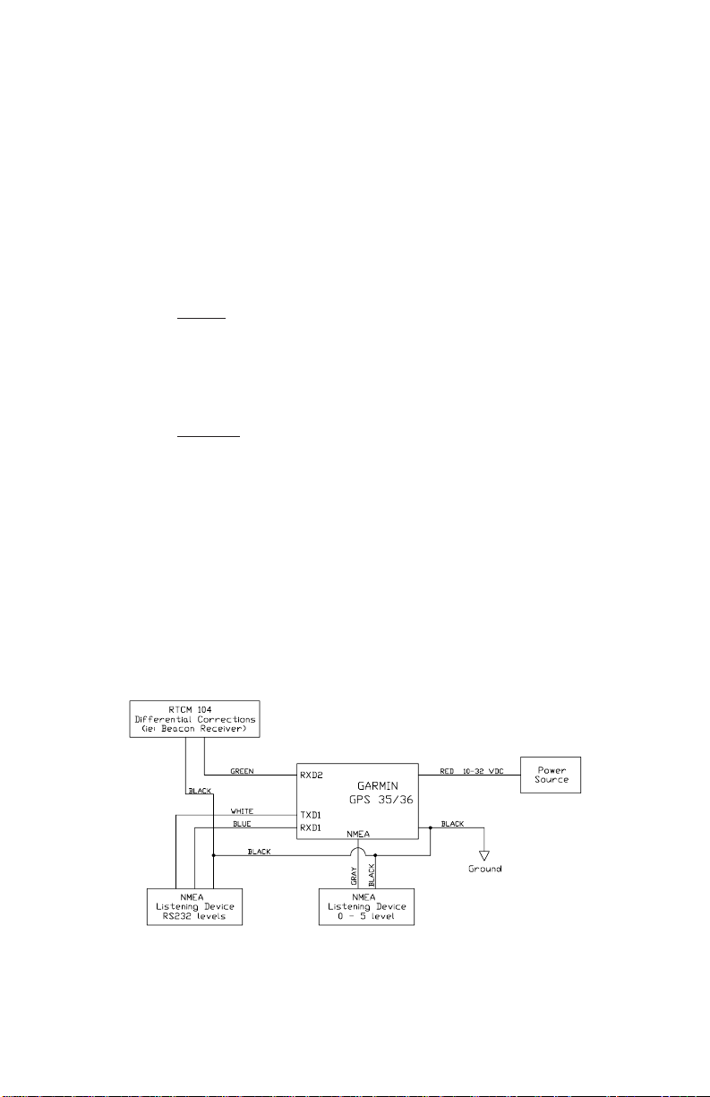
1.4 APPLICATION
TYPICAL APPLICATION ARCHITECTURE
4
Page 10

SECTION 2
OPERATIONAL CHARACTERISTICS
This section describes the basic operational characteristics
of the GPS 35/36. Additional information regarding input
and output specifications are contained in Section 4.
2.1 SELF TEST
After input power has been applied to the GPS 35/36 and
periodically thereafter, the unit will perform critical self test
functions and report the results over the output channel(s).
The following tests will be performed:
1) RAM check
2) ROM test
3) Receiver test
4) Real-time clock test
5) Oscillator check
In addition to the results of the above tests, the GPS 35/36
will report software version information.
2.2 INITIALIZATION
After the initial self test is complete, the GPS 35/36 will begin
the process of satellite acquisition and tracking. The
acquisition process is fully automatic and, under normal
circumstances, will take approximately 45 seconds to
achieve a position fix (15 seconds if ephemeris data is
known). After a position fix has been calculated, valid
position, velocity and time information will be transmitted
over the output channel(s).
5
Page 11

Like all GPS receivers, the GPS 35/36 utilizes initial data
such as last stored position, date and time as well as
satellite orbital data to achieve maximum acquisition
performance. If significant inaccuracy exists in the initial
data, or if the orbital data is obsolete, it may take 5.0 minutes
to achieve a navigation solution. The GPS 35/36 Autolocate
TM
feature is capable of automatically determining a navigation
solution without intervention from the host system. However,
acquisition performance can be improved if the host system
initializes the GPS 35/36 following the occurrence of one or
more of the following events:
1) Transportation over distances further than 1500
kilometers
2) Failure of the internal memory battery without system
standby power
3) Stored date/time off by more than 30 minutes
See Section 4 for more information on initializing the GPS
35/36.
2.3 NAVIGATION
After the acquisition process is complete, the GPS 35/36
will begin sending valid navigation information over its
output channels. These data include:
1) Latitude/longitude/altitude
2) Velocity
3) Date/time
4) Error estimates
5) Satellite and receiver status
Normally the GPS 35/36 will select the optimal navigation
mode (2D or 3D) based on available satellites and geometry
considerations. The host system, at its option, may command
6
Page 12

the GPS 35/36 to choose a specific mode of navigation,
such as 2D. The following modes are available:
1) 2D exclusively with altitude supplied by the host
system (altitude hold mode)
2) 3D exclusively with altitude computed by the GPS 35/
36
3) Automatic mode in which the board set determines
the desired mode based on satellite availability and
geometry considerations
When navigating in the 2D mode (either exclusive or
automatic), the GPS 35/36 utilizes the last computed altitude
or the last altitude supplied by the host system, whichever
is newer. The host system must ensure that the altitude
used for 2D navigation is accurate since the resulting
position error may be as large as the altitude error. See
Section 4 for more information on altitude control.
The GPS 35/36 will default to automatic differential
corrections, attempting to apply them to the satellite data, in
order to produce a differential (DGPS) solution. The host
system, at its option, may also command the GPS 35/36 to
choose differential only mode. When navigating in the
differential only mode, the GPS 35/36 will output a position
only when a differential solution is available.
2.4 SATELLITE DATA COLLECTION
The GPS 35/36 will automatically update satellite orbital
data as it operates. The intelligence of the GPS 35/36
combined with its hardware capability allows these data to
be collected and stored without intervention from the host
system. A few key points should be considered regarding
this process:
1) If the GPS 35/36 is not operated for a period of six (6)
months or more, the unit will “search the sky” in order
to collect satellite orbital information. This process is
7
Page 13

fully automatic and, under normal circumstances, will
take about 5 minutes to achieve a navigation solution.
However, the host system should allow the GPS 35/
36 to remain on for at least 12.5 minutes after the first
satellite is acquired (see Section 4 for more information
on status indications).
2) If the internal memory backup battery fails or is not
installed while the host system power is off and not
connected to standby power, the GPS 35/36 will
search the sky as described above. The system
designer should be aware of the availability of standby
power input to the GPS 35/36 to prevent this situation.
3) If the initial data is significantly inaccurate, the GPS
35/36 will perform an operation known as
AutoLocateTM. This procedure is fully automatic and,
under normal circumstances, will require about 5
minutes to calculate a navigation solution.
AutoLocateTM, unlike search the sky, does not require
that the GPS 35/36 continue to operate after a fix has
been obtained.
8
Page 14

SECTION 3
HARDWARE INTERFACE
3.1 MECHANICAL DIMENSIONS
The GPS 35 is a complete GPS receiver including antenna
in a uniquely styled waterproof package.
3.1.1 GPS 35 Dimensions (General Tolerance ±0.50 mm)
9
Page 15

3.1.2 GPS 36 Dimensions (General Tolerance ±0.50 mm)
10
Page 16

3.2 MOUNTING CONFIGURATIONS AND
OPTIONS
The following mounting options are available for the GPS
35. Mounting is user configurable.
3.2.1 Magnetic Mount
The magnetic mount provides a firm, removable mounting
attachment to any ferrous metal surface.
GPS 35 ONLY
11
Page 17

3.2.2 Trunk Lip Mount
The trunk lip mount provides a semi-permanent attachment
to the trunk lip of most automobiles.
GPS 35 ONLY
12
Page 18

3.2.3 Suction Cup Mount
The suction cup bracket provides a removable mounting
surface attached to the inside of a vehicle's windshield.
GPS 35 ONLY
13
Page 19

3.2.4 Flange Mount
The flange mount allows for a permanent installation on a
flat surface. This mounting configuration is ideal in
applications in which the far side of the mounting surface is
inaccessible.
GPS 35 ONLY
14
Page 20

3.3 CONNECTION WIRING DESCRIPTION
The GPS 35/36 features a stripped and pre-tinned cable
assembly for the greatest connection flexibility. The following
is a functional description of each wire in the cable assembly.
Red: VIN - Unregulated 10 - 30VDC 200 mA
(maximum). Typical operating current is
150 mA.
Black: GND - Power and Signal Ground
White: TXD1 - First Serial Asynchronous Output.
RS-232 compatible electrical specification.
This output normally provides serial data
which is formatted per
Version 2.0”
4800 and 9600 BAUD. This output functions
in parallel with the NMEA output.
Blue: RXD1 - First Serial Asynchronous input.
RS-232 compatible with maximum input
voltage range-25<V <25. This input may
be used to receive serial initialization/
configuration data, as specified in Section
4.1.
. Switchable to 1200, 2400,
“NMEA 0183,
Purple: TXD2 - Second Serial Asynchronous
Output. Electrically identical to TXD1.
Green: RXD2 - Second Serial Asynchronous Input.
Electrically identical to RXD1. This input
may be used to receive serial differential
GPS data formatted per
“RTCM
Recommended Standards For Differential
Navstar GPS Service, Version 2.0”
Section 4 for more details).
Gray: NMEA-NMEA0183, Version 1.5 electrical
specification compatible serial output.
This output is also CMOS compatible with
15
(see
Page 21

a no load voltage swing of 0.2Vdc to 4.8Vdc.
This output normally provides ASCII
sentences formatted per
Version 2.0”
. User selectable baud rates
“NMEA 0183,
of 1200, 2400, 4800, and 9600 are
available. The data output on this pin is
identical to the data output on TXD1.
Yellow: VAUX - Optional External Backup Power
Connection. This is an optional connection.
Internal battery capacity is 180 mA hour.
Typical current requirement is 65 uA @
5VDC. If used, a 4VDC to 30 VDC power
source is required.
16
Page 22

SECTION 4
SOFTWARE INTERFACE
The GPS 35/36 interface protocol design is based on the
National Marine Electronics Association’s NMEA 0183 ASCII
interface specification, which is fully defined in
0183, Version 2.0”
P.O. Box 50040, Mobile, AL, 36605, U.S.A.) and the Radio
Technical Commission for Maritime Services’
Recommended Standards For Differential Navstar GPS
Service, Version 2.0, RTCM Special Committee No. 104”
(copies may be obtained from RTCM, P.O. Box 19087,
Washington, D.C., 20036, U.S.A.). The GPS 35/36 interface
protocol, in addition to transmitting navigation information
as defined by NMEA 0183, transmits additional information
using the convention of GARMIN proprietary sentences.
The following sections describe the data format of each
sentence transmitted and received by the GPS 35/36. The
baud rate selection and RTCM differential GPS input are
also described.
(copies may be obtained from NMEA,
4.1 NMEA RECEIVED SENTENCES
“NMEA
“RTCM
The subsequent paragraphs define the sentences which
can be received on RXD1 by the GPS 35/36. These
sentences are echoed upon receipt to provide handshaking
that the appropriate information was received by the GPS
35/36.
hh = 1 byte checksum
4.1.1 Almanac Information (ALM)
$GPALM,<1>,<2>,<3>,<4>,<5>,<6>,<7>,<8>,<9>,<10>,<11>,
<12>,<13>,<14>,<15>*hh<CR><LF>
The $GPALM sentence can be used to initialize the sensor
17
Page 23

board's stored almanac information if battery back-up has
failed.
<1> Total number of ALM sentences to be transmitted
by the sensor board during almanac download.
This field can be null or any number when sending
almanac to the sensor board.
<2> Number of current ALM sentence. This field can be
null or any number when sending
almanac to the sensor board.
<3> Satellite PRN number, 01 to 32.
<4> GPS week number.
<5> SV health, bits 17-24 of each almanac page.
<6> Eccentricity
<7> Almanac reference time.
<8> Inclination angle.
<9> Rate of right ascension.
<10> Root of semi major axis.
<11> Omega, argument of perigee.
<12> Longitude of ascension node.
<13> Mean anomaly
<14> afo clock parameter
<15> af1 clock parameter
4.1.2 Initialization Information ($PGRMI GARMIN
proprietary format)
The $PGRMI sentence provides information used to initialize
the GPS 35/36 set position and time used for satellite
acquisition. Receipt of this sentence by the GPS 35/36
causes the software to restart the satellite acquisition
process. If there are no errors in the sentence, it will be
echoed upon receipt. If an error is detected, the echoed
PGRMI sentence will contain the current default values.
Current PGRMI defaults can also be obtained by sending
$PGRMIE, to the board.
$PGRMI,<1>,<2>,<3>,<4>,<5>,<6>,<7>*hh<CR><LF>
<1> Latitude, ddmm.mmm format (leading zeros must
be transmitted)
18
Page 24

<2> Latitude hemisphere, N or S
<3> Longitude, dddmm.mmm format (leading zeros
must be transmitted)
<4> Longitude hemisphere, E or W
<5> Current UTC date, ddmmyy format
<6> Current UTC time, hhmmss format
<7> Acquisition Reset, A = begin autolocate, R = restart
acquisition
4.1.3 Configuration Information ($PGRMC GARMIN
proprietary format)
The $PGRMC sentence provides information used to
configure the GPS 35/36 operation. Configuration
parameters are stored in non-volatile memory and retained
between power cycles. The GPS 35/36 will echo this
sentence upon its receipt if no errors are detected. If an
error is detected, the echoed PGRMC sentence will contain
the current default values. Current default values can also
be obtained by sending $PGRMCE, to the board.
$PGRMC,<1>,<2>,<3>,<4>,<5>,<6>,<7>,<8>,<9><10>,<11>
*hh<CR><LF>
<1> Fix mode, A=automatic, 2=2D exclusively (host
system must supply altitude), 3=3D exclusively
<2> Altitude above/below mean sea level, -1500.0 to
18000.0 meters
<3> Earth datum index. If the user datum index (96) is
specified, fields <4> through <8> must contain
valid values. Otherwise, fields <4> through <8>
must be null. Refer to Appendix A for a list of earth
datums and the corresponding earth datum index.
<4> User earth datum semi-major axis, 6360000.0 to
6380000.0 meters (.001 meters resolution)
<5> User earth datum inverse flattening factor, 285.0 to
310.0 (10-9 resolution)
<6> User earth datum delta x earth centered coordinate,
-5000.0 to 5000.0 meters (1 meter resolution)
19
Page 25

<7> User earth datum delta y earth centered coordinate,
-5000.0 to 5000.0 meters (1 meter resolution)
<8> User earth datum delta z earth centered coordinate,
-5000.0 to 5000.0 meters (1 meter resolution)
<9> Differential mode, A = automatic (output DGPS
data when available, non-DGPS otherwise),
D = differential exclusively (output only differential
fixes)
<10> NMEA Baud Rate, 1 = 1200, 2 = 2400, 3 = 4800, 4
= 9600
<11> Velocity filter, 1 = Automatic filter, 2-255 = Filter
time constant (10 = 10 second filter)
<12> Not used. Null field
All configuration changes take effect after receipt of a valid
value except baud rate which takes effect on the next power
cycle or external reset event. Null fields in the configuration
sentence indicate not change in the particular configuration
parameter.
4.1.4 Output Sentence Enable/Disable ($PGRMO
GARMIN proprietary format)
The $PGRMO sentence provides the ability to enable and
disable specific output sentences.
The following sentences are enabled at the factory: GPGSA,
GPGSV, GPRMC, PGRME, PGRMT and PGRMV.
$PGRMO,<1>,<2>*hh<CR><LF>
<1> Target sentence description (e.g., PGRMT,
GPGSV, etc.)
<2> Target sentence mode, where:
0 = disable specified sentence
1 = enable specified sentence
2 = disable all output sentences
3 = enable all output sentences (except
GPALM)
The following notes apply to the PGRMO input sentence:
20
Page 26

1) If the target sentence mode is ‘2’ (disable all) or ‘3’
(enable all), the target sentence description is not
checked for validity. In this case, an empty field is
allowed (e.g., $PGRMO,,3), or the mode field may
contain from 1 to 5 characters.
2) If the target sentence mode is ‘0’ (disable) or ‘1’
(enable), the target sentence description field must
be an identifier for one of the sentences being output
by the GPS 35/36.
3) If either the target sentence mode field or the target
sentence description field is not valid, the PGRMO
sentence will have no effect.
4) $PGRMO,GPLAM,1 will cause the sensor board to
transmit all stored almanac information. All other
NMEA sentence transmission will be temporarily
suspended.
4.2 NMEA TRANSMITTED SENTENCES
The subsequent paragraphs define the sentences which
can be transmitted on TXD1 by the GPS 35/36.
4.2.1 Sentence Transmission Rate
Sentences are transmitted with respect to the user selected
baud rate.
The GPS 35/36 will transmit each sentence (except where
noted in particular transmitted sentence descriptions) at a
periodic rate based on the user selected baud rate and user
selected output sentences. The GPS 35/36 will transmit the
selected sentences contiguously. The contiguous
transmission starts at a GPS second boundary. The length
of the transmission can be determined by the following
equation and tables:
21
Page 27

total characters to be transmitted
Length of transmission =
characters transmitted per sec
Baud characters_transmitted_per_sec
1200 120
2400 240
4800 480
9600 960
Sentence max_characters
GPGGA 72
GPGSA 73
GPGSV 210
GPRMC 70
GPVTG 34
PGRME 36
PGRMT 47
PGRMV 26
PGRMF 79
LCGLL 36
LCVTG 34
The factory set defaults will result in a once per second
transmission at the NMEA specification transmission rate of
4800 baud.
4.2.2 Transmitted Time
The GPS 35/36 outputs UTC (Coordinated Universal Time)
date and time of day in the transmitted sentences. Prior to
the initial position fix, the date and time of day are provided
by the on-board clock. After the initial position fix, the date
and time of day are calculated using GPS satellite
information.
The GPS 35/36 uses information obtained from the GPS
satellites to add or delete UTC leap seconds and correct the
transmitted date and time of day. The transmitted date and
time of day for leap second correction follow the guidelines
22
Page 28

in
“National Institute of Standards and Technology Special
Publication 432 (Revised 1990)”
(for sale by the
Superintendent of Documents, U.S. Government Printing
Office, Washington, D.C., 20402, U.S.A.).
When a positive leap second is required, the second is
inserted beginning at 23h 59m 60s of the last day of a month
and ending at 0h 0m 0s of the first day of the following
month. The minute containing the leap second is 61
seconds long. The GPS 35/36 would have transmitted this
information for the leap second added December 31, 1989
as follows:
Date Time
311289 235959
311289 235960
010190 000000
If a negative leap second should be required, one second
will be deleted at the end of some UTC month. The minute
containing the leap second will be only 59 seconds long. In
this case, the GPS 35/36 will not transmit the time of day 23h
59m 59s for the day from which the leap second is removed.
4.2.3 Global Positioning System Almanac Data
(ALM)
$GPALM,<1>,<2>,<3>,<4>,<5>,<6>,<7>,<8>,<9>,<10>,<11>,
<12>,<13>,<14>,<15>*hh<CR><LF>
Almanac sentences are not normally transmitted. Almanac
transmission can be initiated by sending the sensor board
a $PGRMO,GPALM,1 command. Upon receipt of this
command, the sensor board will transmit available almanac
information on GPALM sentences. During the transmission
of almanac sentences other NMEA data output will be
temporarily suspended.
<field information> can be found in section 4.1.1.
23
Page 29

4.2.4 Global Positioning System Fix Data (GGA)
$GPGGA,<1>,<2>,<3>,<4>,<5>,<6>,<7>,<8>,<9>,M,<10>,M,<11>,
<12>*hh<CR><LF>
<1> UTC time of position fix, hhmmss format
<2> Latitude, ddmm.mmmm format (leading zeros will
be transmitted)
<3> Latitude hemisphere, N or S
<4> Longitude, dddmm.mmmm format (leading zeros
will be transmitted)
<5> Longitude hemisphere, E or W
<6> GPS quality indication, 0 = fix not available, 1 =
Non-differential GPS fix available, 2 = Differential
GPS (DGPS) fix available
<7> Number of satellites in use, 00 to 12 (leading zeros
will be transmitted)
<8> Horizontal dilution of precision, 1.0 to 99.9
<9> Antenna height above/below mean sea level, -
9999.9 to 99999.9 meters
<10> Geoidal height, -999.9 to 9999.9 meters
<11> Differential GPS (RTCM-SC104) data age, number
of seconds since last valid RTCM transmission
(null if non-DGPS)
<12> Differential Reference Station ID, 0000 to 1023
(leading zeros will be transmitted, null if non-DGPS)
4.2.5 GPS DOP and Active Satellites (GSA)
$GPGSA,<1>,<2>,<3>,<3>,<3>,<3>,<3>,<3>,<3>,<3>,<3>,
<3>,<3>,<3>,<4>,<5>,<6>*hh<CR><LF>
<1> Mode, M = manual, A = automatic
<2> Fix type, 1 = not available, 2 = 2D, 3 = 3D
<3> PRN number, 01 to 32, of satellite used in solution,
up to 12 transmitted (leading zeros will be
transmitted)
<4> Position dilution of precision, 1.0 to 99.9
<5> Horizontal dilution of precision, 1.0 to 99.9
<6> Vertical dilution of precision, 1.0 to 99.9
24
Page 30

4.2.6 GPS Satellites in View (GSV)
$GPGSV,<1>,<2>,<3>,<4>,<5>,<6>,<7>,...<4>,<5>,<6>,
<7>*hh<CR><LF>
<1> Total number of GSV sentences to be transmitted
<2> Number of current GSV sentence
<3> Total number of satellites in view, 00 to 12 (leading
zeros will be transmitted)
<4> Satellite PRN number, 01 to 32 (leading zeros will
be transmitted)
<5> Satellite elevation, 00 to 90 degrees (leading zeros
will be transmitted)
<6> Satellite azimuth, 000 to 359 degrees, true (leading
zeros will be transmitted)
<7> Signal to noise ratio (C/No) 00 to 99 dB, null when
not tracking (leading zeros will be transmitted)
NOTE: Items <4>,<5>,<6> and <7> repeat for each satellite
in view to a maximum of four (4) satellites per
sentence. Additional satellites in view information
must be sent in subsequent sentences. These
fields will be null if unused.
4.2.7 Recommended Minimum Specific GPS/
TRANSIT Data (RMC)
$GPRMC,<1>,<2>,<3>,<4>,<5>,<6>,<7>,<8>,<9>,<10>,
<11>*hh<CR><LF>
<1> UTC time of position fix, hhmmss format
<2> Status, A = Valid position, V = NAV receiver warning
<3> Latitude, ddmm.mmmm format (leading zeros will
be transmitted)
<4> Latitude hemisphere, N or S
<5> Longitude, dddmm.mmmm format (leading zeros
will be transmitted)
<6> Longitude hemisphere, E or W
<7> Speed over ground, 0.0 to 999.9 knots
<8> Course over ground, 000.0 to 359.9 degrees, true
(leading zeros will be transmitted)
25
Page 31

<9> UTC date of position fix, ddmmyy format
<10> Magnetic variation, 000.0 to 180.0 degrees (leading
zeros will be transmitted)
<11> Magnetic variation direction, E or W (westerly
variation adds to true course)
4.2.8 Track Made Good and Ground Speed with GPS
Talker ID (GPVTG)
The GPVTG sentence reports track and velocity information
with a checksum:
$GPVTG,<1>,T,<2>,M,<3>,N,<4>,K*hh<CR><LF>
<1> True course over ground, 000 to 359 degrees
(leading zeros will be transmitted)
<2> Magnetic course over ground, 000 to 359 degrees
(leading zeros will be transmitted)
<3> Speed over ground, 00.0 to 99.9 knots (leading
zeros will be transmitted)
<4> Speed over ground, 00.0 to 99.9 kilometers per
hour (leading zeros will be transmitted)
4.2.9 Geographic Position with LORAN Talker ID
(LCGLL)
The LCGLL sentence reports position information.
$LCGLL,<1>,<2>,<3>,<4>,<5>,<CR><LF>
<1> Latitude, ddmm.mm format (leading zeros will be
transmitted)
<2> Latitude hemisphere, N or S
<3> Longitude, dddmm.mm format (leading zeros will be
transmitted)
<4> Longitude hemisphere, E or W
<5> UTC time of position fix, hhmmss format
4.2.10 Track Made Good and Ground Speed with
LORAN Talker ID (LCVTG)
The LCVTG sentence reports track and velocity information.
26
Page 32

$LCVTG,<1>,T,<2>,M,<3>,N,<4>,K<CR><LF>
<1> True course over ground, 000 to 359 degrees
(leading zeros will be transmitted)
<2> Magnetic course over ground, 000 to 359 degrees
(leading zeros will be transmitted)
<3> Speed over ground, 00.0 to 99.9 knots (leading
zeros will be transmitted)
<4> Speed over ground, 00.0 to 99.9 kilometers per
hour (leading zeros will be transmitted)
4.2.11 Estimated Error Information ($PGRME
GARMIN proprietary format)
The $PGRME sentence reports estimated position error
information.
$PGRME,<1>,M,<2>,M,<3>,M*hh<CR><LF>
<1> Estimated horizontal position error (HPE), 0.0 to
9999.9 meters
<2> Estimated vertical position error (VPE), 0.0 to 9999.9
meters
<3> Estimated position error (EPE), 0.0 to 9999.9 meters
4.2.12 GPS Fix Data Sentence ($PGRMF GARMIN
proprietary format)
$PGRMF,<1>,<2>,<3>,<4>,<5>,<6>,<7>,<8>,<9>,<10>,
<11>,<12>,<13>,<14>,<15>,*hh<CR><LF>
<1> GPS week number (0-1023)
<2> GPS seconds (0-604799)
<3> UTC date of position fix, ddmmyy format
<4> UTC time of position fix, hhmmss format
<5> GPS leap second count
<6> Latitude, ddmm.mmmm format (leading zeros will
be transmitted)
<7> Latitude hemisphere, N or S
27
Page 33

<8> Longitude, dddmm.mmmm format (leading zeros
will be transmitted)
<9> Longitude hemisphere, E or W
<10> Mode, M = manual, A = automatic
<11> Fix type, 0 = no fix, 1 = 2D fix, 2 = 3D fix
<12> Speed over ground, 0 to 999 kilometers/hour
<13> Course over ground, 0 to 359 degrees, true
<14) Position dilution of precision, 0 to 9 (rounded to
nearest integer value)
<15> Time dilution of precision, 0 to 9 (rounded to nearest
integer value)
4.2.13 Sensor Status Information ($PGRMT GARMIN
proprietary format)
The $PGRMT sentence gives information concerning the
status of the GPS 35/36. This sentence is transmitted once
per minute regardless of the selected baud rate.
$PGRMT,<1>,<2>,<3>,<4>,<5>,<6>,<7>,<8>*hh<CR><LF>
<1> Product, model and software version, this is a
variable length field. (NOTE: Since the GPS 35/36
utilizes a GPS 25 sensor board, the GPS 25 model
description will appear in this field.)
<2> Rom checksum test, P = pass, F = fail
<3> Receiver failure discrete, P = pass, F = fail
<4> Stored data lost, R = retained, L = lost
<5> Real time clock lost, R = retained, L = lost
<6> Oscillator drift discrete, P = pass, F = excessive
drift detected
<7> Data collection discrete, C = collecting almanac,
null if almanac is current
<8> Unit temperature in degrees C
<9> Board configuration data, R = retained, L = lost
4.2.14 3D velocity information ($PGRMV GARMIN
proprietary format)
The $PGRMV sentence reports three-dimensional velocity
information.
28
Page 34

$PGRMV,<1>,<2>,<3>,*hh<CR><LF>
<1> True east velocity, -999.9 to 9999.9 meters/second
<2> True north velocity, -999.9 to 9999.9 meters/second
<3> Up velocity, -999.9 to 9999.9 meters/second
4.3 BAUD RATE SELECTION
Baud rate selection can be performed by sending the
appropriate configuration sentence to the GPS 35/36 as
described in the NMEA Received Sentences Section,
sentence $PGRMC.
4.4 RTCM RECEIVED DATA
Position accuracy of 3-10 meters can be achieved with the
GPS 35/36 by using Differential GPS (DGPS) real-time
pseudo-range correction data in RTCM SC-104 format.
These corrections can be received by the GPS 35/36 on
RXD2. Correction data at speeds of 300, 600, 1200, 2400,
4800 or 9600 baud can be utilized, as the GPS 35/36
automatically detects the incoming baud rate. For details on
the SC-104 format, refer to
by the Radio Technical Commission for Maritime Services.
RTCM Paper 134-89/SC 104-68
29
Page 35

APPENDIX A
EARTH DATUMS
The following is a list of the GARMIN GPS 35/36 earth
datum indexes and the corresponding earth datum name
(including the area of application):
0 ADINDAN - Ethiopia, Mali, Senegal, Sudan
1 AFGOOYE - Somalia
2 AIN EL ABD 1970 - Bahrain Island, Saudi Arabia
3 ANNA 1 ASTRO 1965 - Cocos Island
4 ARC 1950 - Botswana, Lesotho, Malawi, Swaziland,
Zaire, Zambia, Zimbabwe
5 ARC 1960 - Kenya, Tanzania
6 ASCENSION ISLAND 1958 - Ascension Island
7 ASTRO BEACON ‘‘E’’ - Iwo Jima Island
8 AUSTRALIAN GEODETIC 1966 - Australia,
Tasmania Island
9 AUSTRALIAN GEODETIC 1984 - Australia,
Tasmania Island
10 ASTRO DOS 71/4 - St. Helena Island
11 ASTRONOMIC STATIO N 1952 - Marcus Island
12 ASTRO B4 SOROL ATOLL - Tern Island
13 BELLEVUE (IGN) - Efate and Erromango Islands
14 BERMUDA 1957 - Bermuda Islands
15 BOGOTA OBSERVATORY - Colombia
16 CAMPO INCHAUSPE - Argentina
17 CANTON ASTRO 1966 - Phoenix Islands
18 CAPE CANAVERAL - Florida, Bahama Islands
19 CAPE - South Africa
20 CARTHAGE - Tunisia
21 CHATHAM 1971 - Chatham Island (New Zealand)
22 CHUA ASTRO - Paraguay
23 CORREGO ALEGRE - Brazil
24 DJAKARTA (BATAVIA) - Sumatra Island
(Indonesia)
25 DOS 1968 - Gizo Island (New Georgia Islands)
A1
Page 36

26 EASTER ISLAND 1967 - Easter Island
27 EUROPEAN 1950 - Austria, Belgium, Denmark,
Finland, France, Germany, Gibraltar, Greece, Italy,
Luxembourg, Netherlands, Norway, Portugal,
Spain, Sweden, Switzerland
28 EUROPEAN 1979 - Austria, Finland, Netherlands,
Norway, Spain, Sweden, Switzerland
29 FINLAND HAYFORD 1910 - Finland
30 GANDAJIKA BASE - Republic of Maldives
31 GEODETIC DATUM 1949 - New Zealand
32 ORDNANCE SURVEY OF GREAT BRITAIN 1936
- England, Isle of Man, Scotland, Shetland Islands,
Wales
33 GUAM 1963 - Guam Island
34 GUX 1 ASTRO - Guadalcanal Island
35 HJORSEY 1955 - Iceland
36 HONG KONG 1963 - Hong Kong
37 INDIAN - Bangladesh, India, Nepal
38 INDIAN - Thailand, Vietnam
39 IRELAND 1965 - Ireland
40 ISTS O73 ASTRO 1969 - Diego Garcia
41 JOHNSTON ISLAND 1961 - Johnston Island
42 KANDAWALA - Sri Lanka
43 KERGUELEN ISLAND - Kerguelen Island
44 KERTAU 1948 - West Malaysia, Singapore
45 L.C. 5 ASTRO - Cayman Brac Island
46 LIBERIA 1964 - Liberia
47 LUZON - Mindanao Island
48 LUZON - Phillippines (excluding Mindanao Island)
49 MAHE 1971 - Mahe Island
50 MARCO ASTRO - Salvage Islands
51 MASSAWA - Eritrea (Ethiopia)
52 MERCHICH - Morocco
53 MIDWAY ASTRO 1961 - Midway Island
54 MINNA - Nigeria
55 NORTH AMERICAN 1927 - Alaska
56 NORTH AMERICAN 1927 - Bahamas (excluding
San Salvador Island)
A2
Page 37

57 NORTH AMERICAN 1927 - Central America
(Belize, Costa Rica, El Salvador, Guatemala,
Honduras, Nicaragua)
58 NORTH AMERICAN 1927 - Canal Zone
59 NORTH AMERICAN 1927 - Canada (including
Newfoundland Island)
60 NORTH AMERICAN 1927 - Caribbean (Barbados,
Caicos Islands, Cuba, Dominican Republic, Grand
Cayman, Jamaica, Leeward Islands, Turks Islands)
61 NORTH AMERICAN 1927 - Mean Value (CONUS)
62 NORTH AMERICAN 1927 - Cuba
63 NORTH AMERICAN 1927 - Greenland (Hayes
Peninsula)
64 NORTH AMERICAN 1927 - Mexico
65 NORTH AMERICAN 1927 - San Salvador Island
66 NORTH AMERICAN 1983 - Alaska, Canada,
Central America, CONUS, Mexico
67 NAPARIMA, BWI - Trinidad and Tobago
68 NAHRWAN - Masirah Island (Oman)
69 NAHRWAN - Saudi Arabia
70 NAHRWAN - United Arab Emirates
71 OBSERVATORIO 1966 - Corvo and Flores Islands
(Azores)
72 OLD EGYPTIAN - Egypt
73 OLD HAWAIIAN - Mean Value
74 OMAN - Oman
75 PICO DE LAS NIEVES - Canary Islands
76 PITCAIRN ASTRO 1967 - Pitcairn Island
77 PUERTO RICO - Puerto Rico, Virgin Islands
78 QATAR NATIONAL - Qatar
79 QORNOQ - South Greenland
80 REUNION - Mascar ene Island
81 ROME 1940 - Sardinia Island
82 RT 90 - Sweden
83 PROVISIONAL SOUTH AMERICAN 1956 - Bolivia,
Chile, Colombia, Ecuador, Guyana, Peru,
Venezuela
A3
Page 38

84 SOUTH AMERICAN 1969 - Argentina, Bolivia,
Brazil, Chile, Colombia, Ecuador, Guyana,
Paraguay, Peru, Venezuela, Trinidad and Tobago
85 SOUTH ASIA - Singapore
86 PROVISIONAL SOUTH CHILEAN 1963 - South
Chile
87 SANTO (DOS) - Espirito Santo Island
88 SAO BRAZ - Sao Miguel, Santa Maria Islands
(Azores)
89 SAPPER HILL 1943 - East Falkland Island
90 SCHWARZECK - Namibia
91 SOUTHEAST BASE - Porto Santo and Madeira
Islands
92 SOUTHWEST BASE - Faial, Graciosa, Pico, Sao
Jorge, and Terceira Islands (Azores)
93 TIMBALAI 1948 - Brunei and East Malaysia
(Sarawak and Sabah)
94 TOKYO - Japan, Korea, Okinawa
95 TRISTAN ASTRO 1968 - Tristan da Cunha
96 User defined earth datum
97 VITI LEVU 1916 - Viti Levu Island (Fiji Islands)
98 WAKE-ENIWETO K 1960 - Marshall Islands
99 WORLD GEODETIC SYSTEM 1972
100 WORLD GEODETIC SYSTEM 1984
101 ZANDERIJ - Surinam
102 CH-1903 - Switzerland
103 Hu-Tzu-Shan
104 Indonesia 74
GPS 35/36 Rev. 2.08 or later:
105 Austria
106 Potsdam
107 Taiwan (modified Hu-Tzu-Shan)
A4
Page 39

GARMIN Corporation
1200 E. 151st Street
Olathe, KS 66062
1-800-800-1020
(913)397-8200
190-00104-00 Rev. D
 Loading...