

Garmin Marine Network Cable Connector (RJ45, 2-pack, 20-pack, (RJ45 Installation Instructions Manual
Page 1
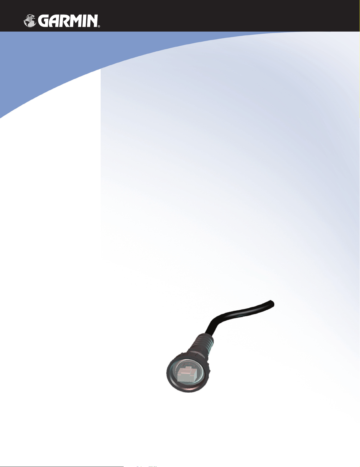
Marine
Ethernet
Connection
installation instructions
Page 2

© Copyright 2004, 2005 Garmin Ltd. or its subsidiaries
Garmin International, Inc.
1200 East 151st Street,
Olathe, Kansas 66062, U.S.A.
Tel. 913/397.8200 or 800/800.1020
Fax 913/397.8282
All rights reserved. Except as expressly provided herein, no part of this manual may be reproduced, copied, transmitted, disseminated, downloaded, or stored in any
storage medium, for any purpose without the express prior written consent of Garmin. Garmin hereby grants permission to download a single copy of this manual onto
a hard drive or other electronic storage medium to be viewed and to print one copy of this manual or of any revision hereto, provided that such electronic or printed
copy of this manual must contain the complete text of this copyright notice and provided further that any unauthorized commercial distribution of this manual or any
revision hereto is strictly prohibited.
Information in this document is subject to change without notice. Garmin reserves the right to change or improve its products and to make changes in the content
without obligation to notify any person or organization of such changes or improvements. Visit the Garmin Web site (
supplemental information concerning the use and operation of this and other Garmin products.
Garmin® is a registered trademark of Garmin Ltd. or its subsidiaries and may not be used without the express permission of Garmin.
Garmin (Europe) Ltd.
Unit 5, The Quadrangle,
Abbey Park Industrial Estate,
Romsey, SO51 9DL, U.K.
Tel. 44/0870.8501241
Fax 44/0870.8501251
Garmin Corporation
No. 68, Jangshu 2nd Road,
Shijr, Taipei County, Taiwan
Tel. 886/2.2642.9199
Fax 886/2.2642.9099
www.garmin.com) for current updates and
Safety Information
WARNING: This product, its packaging, and its components contain chemicals known to the State of California to cause cancer, birth defects, or reproductive harm.
This Notice is being provided in accordance with California’s Proposition 65. If you have any questions or would like additional information, please refer to our Web
site at http://www.garmin.com/prop65
Limited Warranty
This Garmin product is warranted to be free from defects in materials or workmanship for one year from the date of purchase. Within this period, Garmin will at
its sole option repair or replace any components that fail in normal use. Such repairs or replacement will be made at no charge to the customer for parts or labor,
provided that the customer shall be responsible for any transportation cost. This warranty does not cover failures due to installation errors, abuse, misuse, accident, or
unauthorized alteration or repairs.
THE WARRANTIES AND REMEDIES CONTAINED HEREIN ARE EXCLUSIVE AND IN LIEU OF ALL OTHER WARRANTIES EXPRESS OR IMPLIED OR
STATUTORY, INCLUDING ANY LIABILITY ARISING UNDER ANY WARRANTY OF MERCHANTABILITY OR FITNESS FOR A PARTICULAR PURPOSE,
STATUTORY OR OTHERWISE. THIS WARRANTY GIVES YOU SPECIFIC LEGAL RIGHTS, WHICH MAY VARY FROM STATE TO STATE.
IN NO EVENT SHALL GARMIN BE LIABLE FOR ANY INCIDENTAL, SPECIAL, INDIRECT OR CONSEQUENTIAL DAMAGES, WHETHER RESULTING
FROM THE USE, MISUSE, OR INABILITY TO USE THIS PRODUCT OR FROM DEFECTS IN THE PRODUCT. Some states do not allow the exclusion of
incidental or consequential damages, so the above limitations may not apply to you.
Garmin retains the exclusive right to repair or replace the product or offer a full refund of the purchase price at its sole discretion. SUCH REMEDY SHALL BE
YOUR SOLE AND EXCLUSIVE REMEDY FOR ANY BREACH OF WARRANTY.
Products sold through online auctions are not eligible for rebates or other special offers from Garmin. Online auction confirmations are not accepted for warranty
verification. To obtain warranty service, an original or copy of the sales receipt from the original retailer is required. Garmin will not replace missing components from
any package purchased through an online auction.
To obtain warranty service, contact your local Garmin authorized dealer or call Garmin Product Support for shipping instructions and an RMA tracking number. The
product should be securely packed with the tracking number clearly written on the outside of the package. The product should then be sent, freight charges prepaid, to
any Garmin warranty service station. A copy of the original sales receipt is required as the proof of purchase for warranty repairs.
March 2005 Part Number 190-00489-00 Rev. B Printed in Taiwan
Page 3
INTRODUCTION
INTRODUCTION
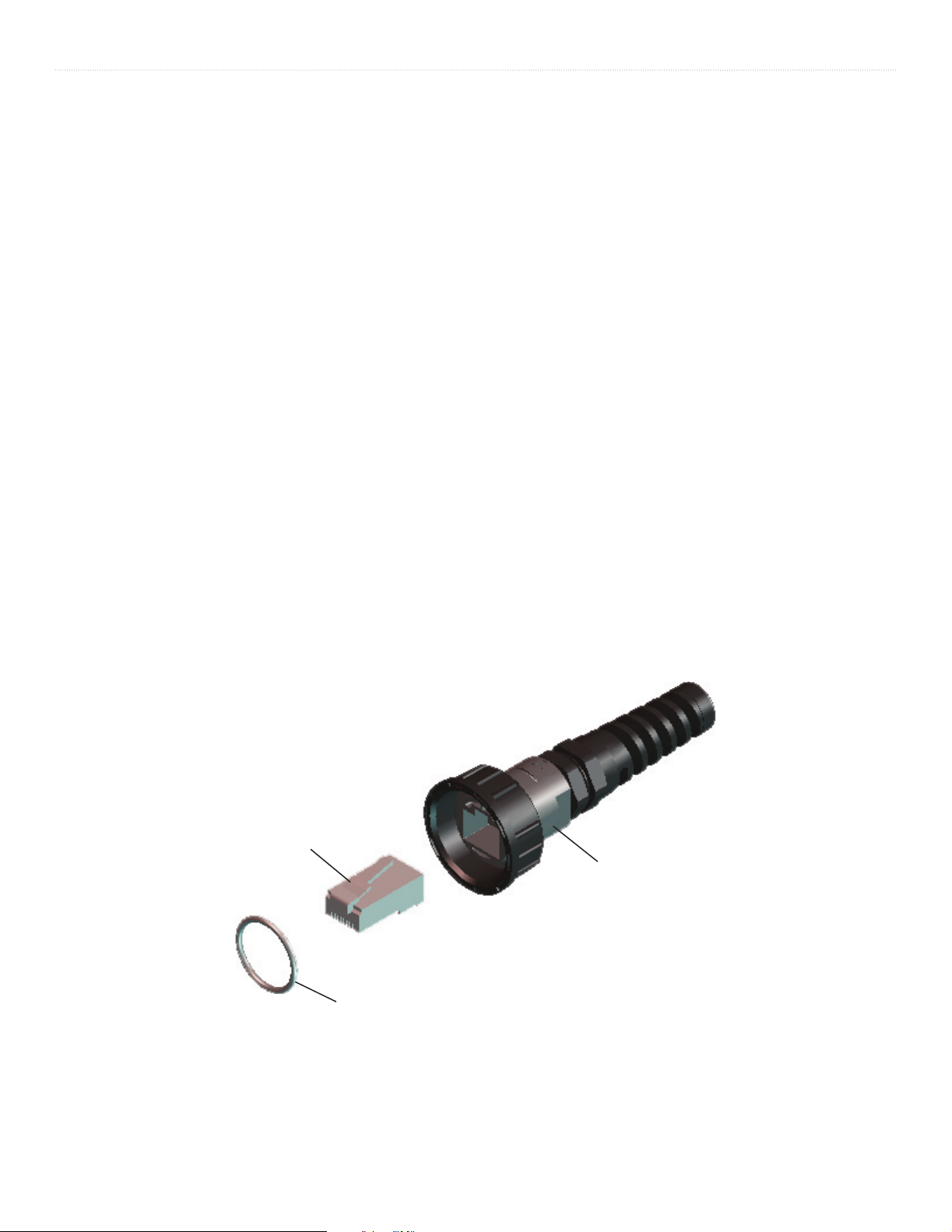
The Ethernet cable termination is designed for use with the Garmin Marine Network. It must be installed according to the following instructions
to get the best possible performance. To complete the installation, you need the appropriate equipment and tools. If you experience diffi culty
with the installation, contact Garmin Product Support.
Included Equipment:
1 - RJ-45 Modular Plug
1 - Ethernet cable termination
1 - O-Ring
1 - Copper Tape Strip
Tools Required:
Knife
Pliers
15 mm Wrench
AMP Modular Plug Hand Tool and Die Set or Compatible equivalent
RJ-45
Modular Plug
Cable
Termination
Marine Ethernet Connection
O-Ring
Figure 1
1
Page 4
INSTALLATION INSTRUCTIONS
INSTALLATION INSTRUCTIONS
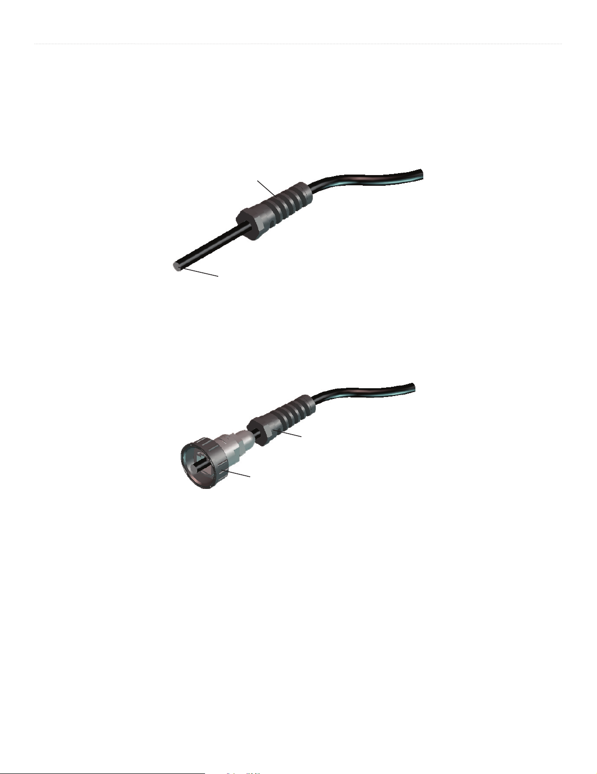
1. Cleanly cut your Ethernet cable to the desired length. Retain the cut connection for Step 4.
2. Remove strain relief nut from cable connection housing and slide onto cut end of the cable as shown in Figure 2.
Strain Relief
Cut End of
Cable
Figure 2
3. Feed the cable end through connection housing and threaded collar as shown in Figure 3.
Strain Relief
Connection
Housing
Figure 3
2 Marine Ethernet Connection
Page 5
INSTALLATION INSTRUCTIONS
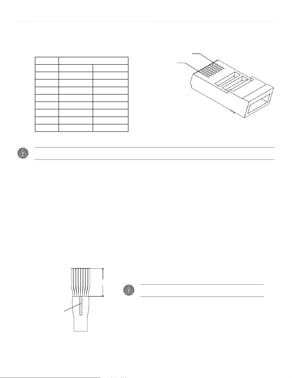
4. Examine the connection removed in Step 1 and compare to the wire positions table and Figure 4. Make note which cable side, A or B,
was removed in Step 1.
Position 8
Position Wire Color—Main/Stripe
Side A
Side B
Position 1
1 White/Orange White/Green
2 Orange Green
3 White/Green White/Orange
4 Blue Blue
5 White/Blue White/Blue
6 Green Orange
7 White/Brown White/Brown
8 Brown Brown
NOTE: The Garmin Marine Network requires cross over cables not exceeding 100 meters between devices. When constructing a custom cable
from bulk wire, you must create both a Side A and Side B.
Figure 4
5. Prepare cable for plug installation according to the following steps:
a. Using a sharp knife, insert blade between the cable shield and jacket. Slit the jacket 5/8" back from the trimmed end of the cable.
b. Peel the jacket back and remove the slit portion.
c. Trim the shield and Mylar fi lm away from wires. Be careful not to cut any of the wires.
d. Fold the drain wire back over the jacket and trim to approximately 5/16" in length.
e. Untwist the wire pairs enough to ensure a proper connection.
f. Arrange individual wires in proper order according to the table shown above. For example, if you have identifi ed the end of the cable
in Step 4 as Side A, arrange the wires for Side A. If you are constructing a custom cable from bulk wire, you need to make both a
Side A and a Side B connection.
g. Trim the wire ends to even length, leaving approximately 9/16" from the ends to the jacket edge as shown in Figure 5.
h. Place the drain wire on the jacket as shown in Figure 5. Wrap the supplied copper tape around cable as close to the edge of the
jacket as possible.
i. Using a pair of pliers, squeeze copper tape to pre-form the cable jacket end for easier insertion into the plug. Use caution to avoid
damaging the copper tape.
9/16"
NOTE: The wires are arranged in twisted pairs. To minimize electronic
interference, only untwist the wires enough to ensure a proper connection.
Drain Wire
Marine Ethernet Connection
Figure 5
3
Page 6
INSTALLATION INSTRUCTIONS
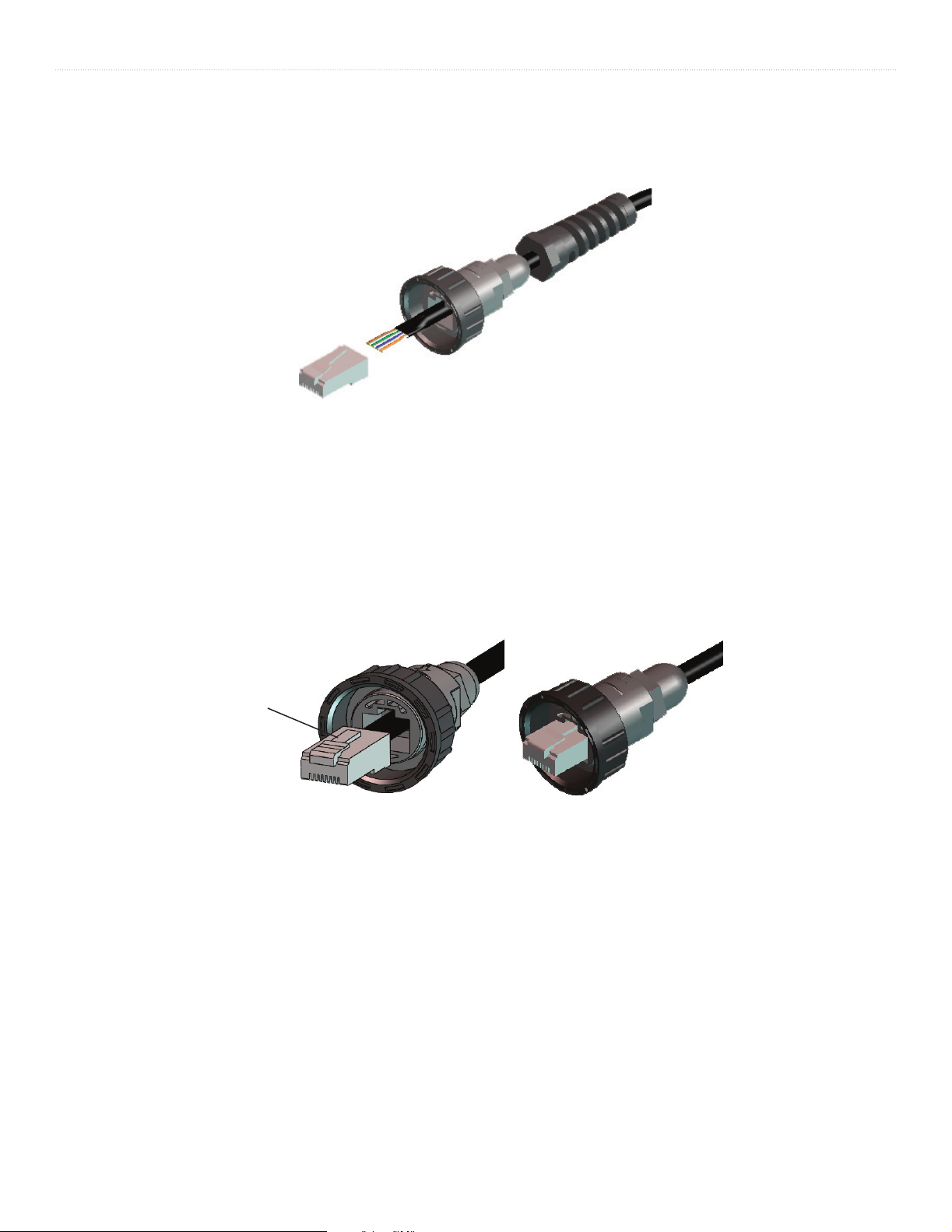
6. Keeping wires in proper sequence, insert them into the modular plug until the ends bottom out inside the plug. Visually inspect the wires
to verify proper order before continuing. If any wires are not in the correct position, remove plug and rearrange the wires.
Figure 6
7. Using AMP Modular Plug Hand Tool and Die Set (or compatible equivalent), crimp the plug onto wires following the crimp tool
manufacturer’s recommended procedure.
8. After the plug is crimped, align release tab on plug with corresponding notch in cable connection housing, refer to Figure 7. Depress the
tab and push cable through connection housing until the plug is securely seated in the plug cavity as shown in Figure 8.
Release Tab
Figure 7
Figure 8
4 Marine Ethernet Connection
Page 7
INSTALLATION INSTRUCTIONS
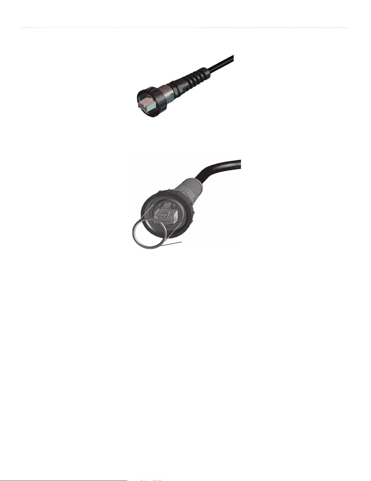
9. Screw strain relief nut onto the housing and tighten snugly with a 15 mm wrench. Be careful not to over tighten the nut.
Figure 9
10. Install the O-ring onto the housing as shown in Figure 10. The cable is now ready for service.
O-Ring
Figure 10
Marine Ethernet Connection
5
Page 8
© Copyright 2004, 2005 Garmin Ltd. or its subsidiaries
Garmin International, Inc.
1200 East 151st Street, Olathe, Kansas 66062, U.S.A.
Garmin (Europe) Ltd.
Unit 5, The Quadrangle, Abbey Park Industrial Estate, Romsey, SO51 9DL, U.K.
Garmin Corporation
No. 68, Jangshu 2nd Road, Shijr, Taipei County, Taiwan
www.garmin.com
Part Number 190-00489-00 Rev. B
 Loading...