

Page 1
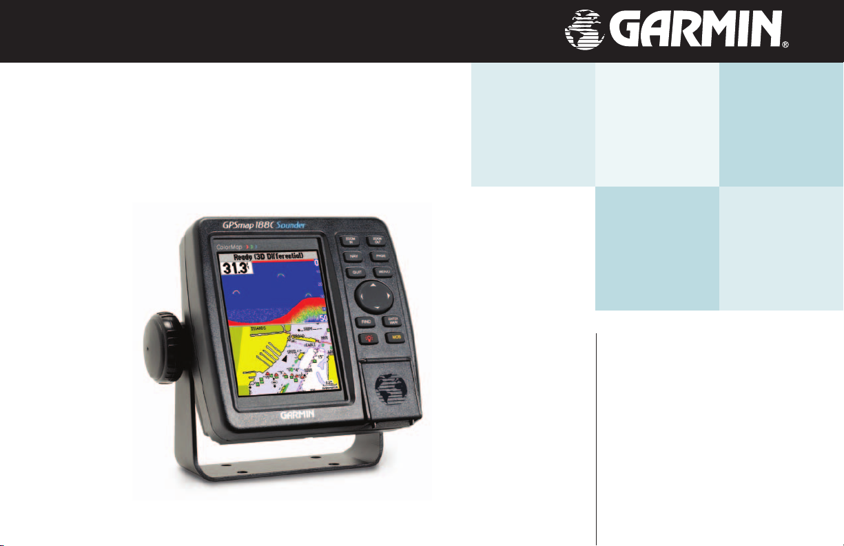
GPSMAP 188/188C/238 Sounder
chartplotting receiver
& depth-fi nder
owner’s
manual
and
reference
(GPSMAP 188C Shown)
guide
Page 2

© Copyright 2003 Garmin Ltd. or its subsidiaries
Garmin International, Inc.
1200 East 151st Street, Olathe, KS 66062, U.S.A.
Tel. 913/397.8200 or 800/800.1020 Fax 913/397.8282
Garmin (Europe) Ltd.
Unit 5, The Quadrangle, Abbey Park Industrial Estate, Romsey SO51 9DL, U.K.
Tel. 44/1794.519944 Fax 44/1794.519222
Garmin Corporation
No. 68, Jangshu 2nd Road, Shijr, Taipei County, Taiwan
Tel. 886/2.2642.9199 Fax 886/2.2642.9099
All Rights Reserved. Except as expressly provided herein, no part of this manual may be reproduced, copied, transmitted, disseminated, downloaded or
stored in any storage medium, for any purpose without prior written consent of Garmin. Garmin hereby grants permission to download a single copy of this
manual and of any revision of this manual onto a hard drive or other electronic storage medium to be viewed and to print one copy of this manual or any
revision hereto, provided that such electronic or printed copy of this manual or revision must contain the complete text of this copyright notice and provided
further that any unauthorized commercial distribution of this manual or any revision hereto is strictly prohibited.
Information in this manual is subject to change without notice. Garmin reserves the right to change or improve its products and to make changes in the content without obligation to notify any person or organization of such changes. Visit the Garmin web site (www.garmin.com) for current updates and supplemental information concerning the use and operation of this and other Garmin products.
GARMIN®, AutoLocate®, GPSMAP®, See-Thru®, DCG (Depth Control Gain)®, MapSource®, BlueChart®, and TracBack® are registered trademarks of Garmin
Ltd. or its subsidiaries and may not be used without the express permission of Garmin.
June 2003 Part Number 190-00216-10 Rev. A Printed in Taiwan
Page 3
Preface
Congratulations on choosing one of the most advanced marine navigation systems available! The
Garmin GPSMAP
tured mapping to create an unsurpassed marine navigation chartplotters.
This manual covers instructions for the GPSMAP 188, GPSMAP 188C (color), and GPSMAP 232.
Unit operation and specifi cations will be the same on all three models, unless otherwise specifi ed. To get the most out of your new navigation system, take the time to go through this owner’s manual
and learn the operating procedures for your unit. This manual is broken down into two parts for your
convenience.
Part One introduces you to the GPSMAP 188/188C/238 Sounder and provides a Getting Started tour
so that you may become more familiar with the unit. This section will provide you with a basic working
knowledge necessary to use the unit to its fullest potential.
Part Two is divided into sections that provide detailed references to the advanced features and operations of the GPSMAP 188/188C/238 Sounder. This allows you to concentrate on a specifi c topic quickly
and look up detailed information about the GPSMAP 188/188C/238 Sounder.
Customer Service Product Registration
Help us better support you by completing our on-line registration today!
Have the serial number of your GPSMAP 188/188C/238 handy and connect to our web site
(www.garmin.com). Look for the Product Registration link on the Home page. Also, be sure to record
your serial number in the area provided on page iv of this manual.
)
®
188/188C/238 Sounders utilize the proven performance of Garmin GPS and full fea-
NOTE: If you have previously registered a Garmin product purchase, we invite you to
re-register using our NEW on-line system. Many services provided by our new product
registration system are now being automated and re-registering your purchase ensures
you the best possible support from Garmin.
Introduction
Preface and
Registration
i
Page 4

Introduction
FCC Compliance
FCC Compliance
The GPSMAP 188/188C/238 Sounder complies with Part 15 of the FCC interference limits for Class
B digital devices FOR HOME OR OFFICE USE. These limits are designed to provide more reasonable protection against harmful interference in a residential installation, and are more stringent than
“outdoor” requirements.
Operation of this device is subject to the following conditions: (1) This device may not cause harmful
interference, and (2) this device must accept any interference received, including interference that may
cause undesired operation.
This equipment generates, uses and can radiate radio frequency energy and, if not installed and used in
accordance with the instructions, may cause harmful interference to radio communications. However,
there is no guarantee that interference will not occur in a particular installation. If this equipment does
cause harmful interference to radio or television reception, which can be determined by turning the
equipment off and on, the user is encouraged to try to correct the interference by one of the following
measures:
• Reorient or relocate the receiving antenna.
• Increase the separation between the equipment and the receiver.
• Connect the equipment into an outlet on a circuit different from that to which the receiver is
connected.
• Consult the dealer or and experienced radio/TV technician for help.
The GPS 188C Sounder does not contain any user-serviceable parts. Repairs should only be made by
an authorized Garmin service center. Unauthorized repairs or modifi cations could result in permanent
damage to the equipment, and void your warranty and your authority to operated this device under
Part 15 regulations.
ii
Page 5

The GPS system is operated by the United States government, which is solely responsible for its accuracy
and maintenance. The system is subject to changes which could affect the accuracy and performance of all GPS
equipment. Although the Garmin GPSMAP 188/188C/238 is a precision electronic NAVigation AID (NAVAID),
any NAVAID can be misused or misinterpreted and, therefore, become unsafe.
Introduction
Warnings and Cautions
The electronic chart is an aid to navigation and is designed to facilitate the use of authorized government
charts, not replace them. Only offi cial government charts and notices to mariners contain all information needed
for safe navigation – and, as always, the user is responsible for their prudent use.
Use the GPSMAP 188/188C/238 at your own risk. To reduce the risk of unsafe operation, carefully review
and understand all aspects of this Owner’s Manual—and thoroughly practice operation using the simulator
mode prior to actual use. When in actual use, carefully compare indications from the GPSMAP 188/188C/238 to
all available navigation sources, including the information from other NAVAIDs, visual sightings, charts, etc. For
safety, always resolve any discrepancies before continuing navigation.
FCC Compliance
,
MAP DATA INFORMATION: One of the goals of
Garmin is to provide customers with the most complete and
accurate cartography that is available to us at a reasonable
cost. We use a combination of governmental and private
data sources, which we identify (as required) in product literature and copyright messages displayed to the consumer.
Virtually all data sources contain inaccurate or incomplete
data to some degree. This is particularly true outside the
United States, where complete and accurate digital data is
either not available or prohibitively expensive.
The GPSMAP 188/188C/238 complies with Part 15 of the FCC interference limits for Class B digital devices
FOR HOME OR OFFICE USE. These limits are designed to provide reasonable protection against harmful
interference in a residential installation, and are more stringent than “outdoor” requirements. Operation of this
device is subject to the following conditions: (1) This device may not cause harmful interference, and (2) this
device must accept any interference received, including interference that may cause undesired operation. This
equipment generates, uses and can radiate radio frequency energy and, if not installed and used in accordance
with the instructions, may cause harmful interference to radio communications. However, there is no guarantee
CAUTION: IT IS THE USER’S RESPONSIBILITY TO
USE THIS PRODUCT PRUDENTLY. THIS PRODUCT IS
INTENDED TO BE USED ONLY AS A NAVIGATIONAL
AID AND MUST NOT BE USED FOR ANY PURPOSE
REQUIRING PRECISE MEASUREMENT OF DIRECTION, DISTANCE, LOCATION, OR TOPOGRAPHY.
that interference will not occur in a particular installation. If this equipment does cause harmful interference
to radio or television reception, which can be determined by turning the equipment off and on, the user is
encouraged to try to correct the interference by one or more of the following measures: Reorient or relocate the
receiving antenna. Increase the separation between the equipment and receiver. Connect the equipment into an
outlet on a circuit different from that to which the receiver is connected. Consult the dealer or an experienced
radio/TV technician for help.
The GPSMAP 188/188C/238 does not contain any user-serviceable parts. Repairs should only be made by
an authorized Garmin service center. Unauthorized repairs or modifi cations could result in permanent damage
WARNING: This product, its packaging, and its components contain chemicals known to the State of California
to cause cancer, birth defects, or reproductive harm. This
Notice is being provided in accordance with California’s
Proposition 65. If you have any questions or would like
additional information, please refer to our web site at http:
//www.garmin.com/prop65.
to the equipment, and void your warranty and your authority to operate this device under Part 15 regulations.
iii
Page 6

Introduction
Warranty and
Serial Number
Serial Number
Use this area to record the serial number (8-digit number
located on the back of the unit) in case it is lost, stolen, or
needs service. Be sure to keep your original sales receipt in a
safe place or attach a photocopy inside the manual.
Serial Number:
*
*
,
The GPSMAP 188/188C/238 Sounder is fastened shut with
screws. Any attempt to open the case to change or modify
the unit in any way will void your warranty and may result
in permanent damage to the equipment.
iv
LIMITED WARRANTY
This Garmin product is warranted to be free from defects in materials or workmanship for one year from
the date of purchase. Within this period, Garmin will at its sole option, repair or replace any components
that fail in normal use. Such repairs or replacement will be made at no charge to the customer for parts or
labor, provided that the customer shall be responsible for any transportation cost. This warranty does not
cover failures due to abuse, misuse, accident or unauthorized alteration or repairs.
THE WARRANTIES AND REMEDIES CONTAINED HEREIN ARE EXCLUSIVE AND IN LIEU OF ALL
OTHER WARRANTIES EXPRESS OR IMPLIED OR STATUTORY, INCLUDING ANY LIABILITY ARISING
UNDER ANY WARRANTY OF MERCHANTABILITY OR FITNESS FOR A PARTICULAR PURPOSE, STATUTORY OR OTHERWISE. THIS WARRANTY GIVES YOU SPECIFIC LEGAL RIGHTS, WHICH MAY VARY
FROM STATE TO STATE.
IN NO EVENT SHALL GARMIN BE LIABLE FOR ANY INCIDENTAL, SPECIAL, INDIRECT OR
CONSEQUENTIAL DAMAGES, WHETHER RESULTING FROM THE USE, MISUSE, OR INABILITY TO
USE THIS PRODUCT OR FROM DEFECTS IN THE PRODUCT. Some states do not allow the exclusion of
incidental or consequential damages, so the above limitations may not apply to you.
Garmin retains the exclusive right to repair or replace the unit or software or offer a full refund of the
purchase price at its sole discretion. SUCH REMEDY SHALL BE YOUR SOLE AND EXCLUSIVE REMEDY
FOR ANY BREACH OF WARRANTY.
To obtain warranty service, contact your local Garmin authorized dealer. Or call Garmin Customer Service at one of the numbers shown below, for shipping instructions and an RMA tracking number. The unit
should be securely packed with the tracking number clearly written on the outside of the package. The unit
should then be sent, freight charges prepaid, to any Garmin warranty service station. A copy of the original
sales receipt is required as the proof of purchase for warranty repairs.
Products sold through online auctions are not eligible for rebates or other special offers from Garmin.
Online auction confi rmations are not accepted for warranty verifi cation. To obtain warranty service, an
original or copy of the sales receipt from the original retailer is required. Garmin will not replace missing
components from any package purchased through an online auction.
Garmin International, Inc. Garmin (Europe) Ltd.
1200 East 151st Street Unit 4, The Quadrangle, Abbey Park Industrial Estate
Olathe, Kansas 66062, U.S.A. Romsey, SO51 9DL, U.K.
Phone: 913/397.8200 Phone: 44/1794.519944
USA Only: 800/800.1020 FAX: 44/1794.519222
FAX: 913/397.0836
Page 7

Software License Agreement
BY USING THE GPSMAP 188/188C/238, YOU AGREE TO BE BOUND BY THE TERMS AND CONDITIONS OF THE FOLLOWING SOFTWARE LICENSE AGREEMENT. PLEASE READ THIS AGREEMENT CAREFULLY.
Garmin grants you a limited license to use the software embedded in this device (the “Software”) in
binary executable form in the normal operation of the product. Title, ownership rights and intellectual
property rights in and to the Software remain in Garmin.
You acknowledge that the Software is the property of Garmin and is protected under the United
States of America copyright laws and international copyright treaties. You further acknowledge that the
structure, organization and code of the Software are valuable trade secrets of Garmin and that the Software
in source code form remains a valuable trade secret of Garmin. You agree not to decompile, disassemble,
modify, reverse assemble, reverse engineer or reduce to human readable form the Software or any part
thereof or create any derivative works based on the Software. You agree not to export or re-export the
Software to any country in violation of the export control laws of the United States of America.
Introduction
Software License Agreement
v
Page 8

Introduction
the following items. If any parts are missing, please contact your Garmin dealer immediately.
Packing List
,
GPSMAP 188/188C/238 Sounder
Standard and Optional Transducers
Unit part numbers 010-00268-01, 010-00239-02, 01000239-03, and 010-00250-11 include a 200/50kHz, 10/40
degree, plastic, depth and temp, transom mount transducer.
For a complete list of optional transducers, see page 96.
For the most recent list of available accessories for
your GPS unit, current user manuals and software
updates, visit our web site at www.garmin.com.
Before installing and getting started with your unit, please check to see that your package includes
Standard Package:
• GPSMAP 188/188C/238 Sounder Unit
• GA 29 External Antenna and 30’ cable
• Gimbal Mount and Knobs
• Power/Data Cable
• Owner’s Manual
• Quick Reference Card
• Protective Cover
Optional Accessories:
• US A/C PC Adapter
• EURO A/C PC Adapter
• Cigarette Lighter Adapter
• BlueChart Marine Data Cards, MapSource CDs, USB Data Card Programmer and Data Cards
• USB Data Card Programmer
• GBR21 Beacon Receiver for differential corrections; GA 22 H-Field Antenna
• 2nd Mounting Station
®
• Marine Swivel Mount, 1” RAM
Mount (GPSMAP 188 with external antenna only)
vi
Page 9

Designed for detailed electronic charting capability, the Garmin GPSMAP 188/188C/238 Sounder is
a powerful navigation device that can give you the information you need:
Precision Performance
• 188C: High-contrast, 16-color LCD screen with backlighting; 188/238: High-contrast, ten-level
gray, LCD screen with backlighting
• 12-channel parallel receiver tracks and uses up to 12 satellites for fast, accurate positioning
• WAAS Capable — receive signals from the additional set of WAAS (Wide Area Augmentation
System) satellites to give you better accuracy
• Differential-Ready — just add an optional Garmin beacon receiver for better than 5-meter accuracy
• Fully gasketed, high-impact plastic alloy case, waterproof to IEC 529 IPX7
Advanced Navigating and Plotting
• 3000 alphanumeric waypoints with selectable icons and comments
• Built-in Worldwide marine basemap to 20 miles includes detailed ocean, river and lake coastlines, cities, interstates, US state highways, and local thoroughfares
• 50 reversible routes with up to 254 (188C; 50 on 188/238) waypoints each
• Uploadable maps using Garmin’s MapSource™ PC products and BlueChart™ Data Cards
• Coordinates: Lat/Lon, UTM/UPS, Loran TD, plus over 20 grids, including Maidenhead
• TracBack route feature which allows you to quickly retrace your track log to a starting position
• Built-in simulator mode
• Built-in tide information from over 3,000 tide stations around the USA coastline, Alaska,
Hawaii, western Canada and several Caribbean Islands
Superior Fishfi nding Ability
• Whiteline feature provides a clear image of both bottom hardness and structure
• See-Thru
®
technology which helps separate fi sh returns from thermoclines and structure
• Four zoom levels with a moving view window
• Underwater waypoint marking
• Map/Sonar split screen combines navigation and fi shfi nding information
• Fish and depth alarms
Introduction
Capabilities
vii
Page 10

Introduction
Table of Contents
Introduction . . . . . . . . . . . . . . . . . . . . . . . . . . i-viii
Preface and Registration . . . . . . . . . . . . . . . . . . i
FCC Compliance . . . . . . . . . . . . . . . . . . . . . . .ii
Warnings and Cautions . . . . . . . . . . . . . . . . . iii
Warranty . . . . . . . . . . . . . . . . . . . . . . . . . . . . iv
Software License Agreement . . . . . . . . . . . . . . . v
Packing List . . . . . . . . . . . . . . . . . . . . . . . . . . vi
Capabilities . . . . . . . . . . . . . . . . . . . . . . . . . . vii
Table of Contents . . . . . . . . . . . . . . . . . . . . . viii
Section One: Getting Started . . . . . . . . . . . . 1-21
Keypad Usage . . . . . . . . . . . . . . . . . . . . . . . . . . 1
Initializing the Receiver . . . . . . . . . . . . . . . . . .2
Selecting Options & Entering Data . . . . . . . . . . 4
Backlighting . . . . . . . . . . . . . . . . . . . . . . . . . . .7
Simulator . . . . . . . . . . . . . . . . . . . . . . . . . . . . .7
Map Page . . . . . . . . . . . . . . . . . . . . . . . . . . . . .8
Going to a Destination . . . . . . . . . . . . . . . . . .11
Sonar Page . . . . . . . . . . . . . . . . . . . . . . . . . . .14
Compass Page . . . . . . . . . . . . . . . . . . . . . . . .16
Numbers Page . . . . . . . . . . . . . . . . . . . . . . . . 16
Highway Page . . . . . . . . . . . . . . . . . . . . . . . . .17
viii
Active Route Page . . . . . . . . . . . . . . . . . . . . . .19
Main Menu Page . . . . . . . . . . . . . . . . . . . . . . .20
Section Two: Reference . . . . . . . . . . . . . . . . 22-77
Map Page . . . . . . . . . . . . . . . . . . . . . . . . . . . .22
Using the Cursor . . . . . . . . . . . . . . . . . . .22
Selecting Map Scales . . . . . . . . . . . . . . . . .24
Map Page Options . . . . . . . . . . . . . . . . . .25
Sonar Page . . . . . . . . . . . . . . . . . . . . . . . . . . .33
Using the Adjustment Menu . . . . . . . . . . .33
Sonar Page Options . . . . . . . . . . . . . . . . .36
Compass Page . . . . . . . . . . . . . . . . . . . . . . . .41
Numbers Page . . . . . . . . . . . . . . . . . . . . . . . . 42
Highway Page . . . . . . . . . . . . . . . . . . . . . . . . .42
Waypoints . . . . . . . . . . . . . . . . . . . . . . . . . . .44
Creating . . . . . . . . . . . . . . . . . . . . . . . . . .44
Reviewing and Editing . . . . . . . . . . . . . . .48
Going to a Destination . . . . . . . . . . . . . . . . . .53
Go To . . . . . . . . . . . . . . . . . . . . . . . . . . . .53
TracBack . . . . . . . . . . . . . . . . . . . . . . . . . .54
MOB Key . . . . . . . . . . . . . . . . . . . . . . . . . . . .56
Routes . . . . . . . . . . . . . . . . . . . . . . . . . . . . . . 57
Creating . . . . . . . . . . . . . . . . . . . . . . . . . .57
Following . . . . . . . . . . . . . . . . . . . . . . . . .58
Route List Page . . . . . . . . . . . . . . . . . . . . .59
Route Review Page . . . . . . . . . . . . . . . . . .60
Active Route Page . . . . . . . . . . . . . . . . . . . . . .64
Find Key . . . . . . . . . . . . . . . . . . . . . . . . . . . . 65
Main Menu Page . . . . . . . . . . . . . . . . . . . . . . .67
GPS Tab . . . . . . . . . . . . . . . . . . . . . . . . . .68
Tide Tab . . . . . . . . . . . . . . . . . . . . . . . . . . 72
Trip Tab . . . . . . . . . . . . . . . . . . . . . . . . . .74
Celestial Tab . . . . . . . . . . . . . . . . . . . . . . .74
Track Tab . . . . . . . . . . . . . . . . . . . . . . . . .75
DSC Tab . . . . . . . . . . . . . . . . . . . . . . . . . .77
Card Tab . . . . . . . . . . . . . . . . . . . . . . . . . .82
Time Tab . . . . . . . . . . . . . . . . . . . . . . . . .82
Pages Tab . . . . . . . . . . . . . . . . . . . . . . . . .83
Temp Tab . . . . . . . . . . . . . . . . . . . . . . . . .84
System Tab . . . . . . . . . . . . . . . . . . . . . . . . 84
Units Tab . . . . . . . . . . . . . . . . . . . . . . . . .85
Communication Tab . . . . . . . . . . . . . . . . . 87
Alarm Tab . . . . . . . . . . . . . . . . . . . . . . . . . 90
Appendices . . . . . . . . . . . . . . . . . . . . . . . . 92-121
Appendix A: Installation . . . . . . . . . . . . . . . . . 92
Appendix B: Data Cards . . . . . . . . . . . . . . . .100
Appendix C: Maintenance . . . . . . . . . . . . . .101
Appendix D: Loran TD . . . . . . . . . . . . . . . . .102
Appendix E: Map Datum . . . . . . . . . . . . . . . 104
Appendix F: Messages . . . . . . . . . . . . . . . . .106
Appendix G: Navigation Terms . . . . . . . . . . .108
Appendix H: Time Offsets . . . . . . . . . . . . . .110
Appendix I: Understanding Sonar . . . . . . . .111
Appendix J: Specifi cations . . . . . . . . . . . . . .116
Appendix K: Index . . . . . . . . . . . . . . . . . . . .118
Page 11
Using the Keypad
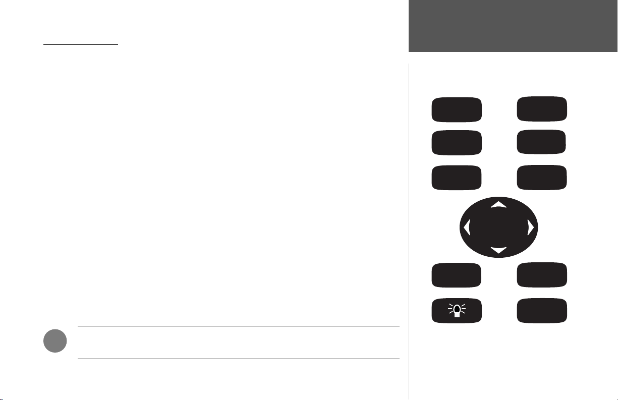
ZOOM IN Key— adjusts the map scale to display a smaller area with more detail (Zooms in).
ZOOM OUT Key— adjusts the map scale to display a larger area with less detail (Zooms out).
Getting Started
Keypad Usage
NAV Key— displays the Go To and Follow navigation menu.
PAGE Key— selects the main pages in sequence and returns display from a submenu page.
QUIT Key— returns the display to the previous page and, when entering data, it restores the previous
value (cancels data entry).
MENU Key— displays a menu of available options for the current page. Press twice to display the
Main Menu.
ARROW KEYPAD— used to select (Highlight) menu options and enter data. It also controls cursor
movement on the Map Page.
FIND Key— activates the fi nd function to search for nearby items and user waypoints.
ENTER/MARK Key— selects a highlighted menu option. When entering data, it allows you to initiate
entry, and then to accept the selected value(s). It also marks the current location as a waypoint when
pressed and held for more than one second.
MOB (Man OverBoard) Key— activates the Man OverBoard navigation feature when pressed.
POWER/BACKLIGHT/CONTRAST Key— turns the unit on/off and adjusts display illumination.
Also controls Contrast on monochrome units.
)
NOTE: Always press and release a key to perform its primary function. Pressing and
holding the ENTER/MARK key will activate its secondary function.
ZOOM
IN
NAV
QUIT
FIND
ZOOM
OUT
PAG E
MENU
ENTER
MARK
MOB
1
Page 12
Getting Started
Initializing the Receiver/
Power On
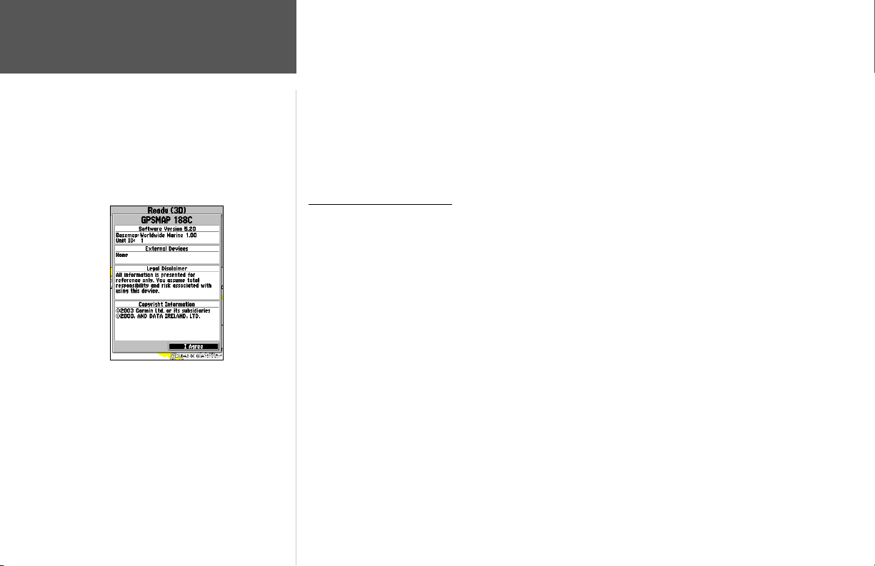
GPSMAP 188/188C/238 Sounder Warning Screen
The GPSMAP 188/188C/238 Sounder’s advanced keypad system is designed to allow for fast, convenient selection of navigation options and data entry. The Getting Started Tour will introduce you to
the keypad and provide a ‘hands-on’ lesson in using the GPSMAP 188/188C/238 Sounder. We strongly
encourage you to follow the Getting Started tour before using your unit for actual navigation.
The GPSMAP 188/188C/238 Sounder Quick Reference Guide contains helpful tips on using the
unit and performing various navigation tasks. It’s a good idea to keep the Quick Reference Guide
nearby whenever you’re operating your GPSMAP 188/188C/238 Sounder.
Initializing the Receiver
The fi rst time you power up your GPSMAP 188/188C/238 Sounder, the receiver must be given an
opportunity to collect satellite data and establish its present position. To ensure proper initialization,
the GPSMAP 188/188C/238 Sounder is shipped from the factory in AutoLocate mode, which allows
the receiver to “fi nd itself” anywhere in the world. To speed up the initialization process, we recommend using the graphic initialization process described on the next page, which usually provides a
position fi x within a few minutes.
Before you initialize, make sure the GPSMAP 188/188C/238 Sounder unit and antenna have been
correctly installed on your vessel according to the instructions in Appendix A. The antenna needs to be
in a location with a clear and unobstructed view of the sky to receive satellite signals.
To turn on the GPSMAP 188/188C/238 Sounder:
1. Press and hold the POWER key until the power tone sounds and the display comes on, then release
the POWER key. A warning page appears, asking you to read and acknowledge important information regarding the use of the unit.
2. After reading the warning, press ENTER to agree and move to the next display.
2
Page 13
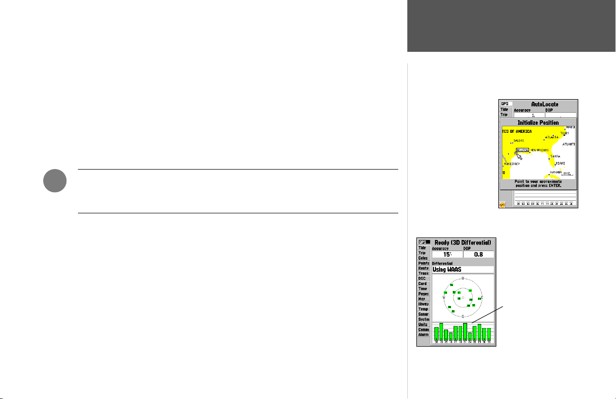
To graphically initialize the GPSMAP 188/188C/238 Sounder:
1. Press the MENU key twice for the Main Menu. Press Up or Down on the ARROW KEYPAD until
the ‘GPS’ tab is highlighted, then press the MENU key once.
2. Using the ARROW KEYPAD, highlight ‘Initialize Position’ and press ENTER to initialize the
receiver from the map. The Initialize Position Page appears, prompting you to select your
approximate location with the map cursor.
3. Use the ARROW KEYPAD to move the map cursor and point to your approximate location within
200 miles. If you have diffi culty identifying your position, press and release the IN key to see the
next lower map scale.
4. Once you have determined your approximate location on the map, press the ENTER key.
,
NOTE: This does not “calibrate” the unit in any way, but rather helps to speed up the
initial satellite acquisition. If the unit displays “Ready (2D) or (3D )” during this
process, it is not necessary to initialize the unit.
The GPSMAP 188/188C/238 Sounder will now begin searching for the appropriate satellites for
your region and should acquire a fi x within a few minutes. When viewing the ‘GPS’ tab on the Main
Menu, a signal strength bar for each satellite in view appears on the bottom of the page, with the
appropriate satellite number under each bar. The progress of satellite acquisition is shown in three
stages:
• No signal strength bars— the receiver is looking for the satellites indicated.
• Hollow signal strength bars— the receiver has found the indicated satellites and is collecting data.
• Solid signal strength bars— the receiver has collected the necessary data and the satellites are ready
for use.
Once the receiver has collected information from at least three satellites, the top of the screen
displays either “Ready (2D or 3D)”, and the GPSMAP 188/188C/238 Sounder is ready for use.
Getting Started
Initializing the Receiver
Point to your approximate
location and press
ENTER/MARK.
A satellite’s strength bars
turn green when it’s ready
for use.
3
Page 14
Getting Started
Selecting Options
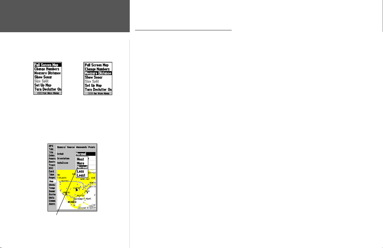
Options Menu with
highlighted option.
Use the ARROW
KEYPAD to highlight
the next option. Press
ENTER/MARK to
activate.
Selecting Options and Entering Data
Before moving ahead into the features of the GPSMAP 188/188C/238 Sounder, you will need to
learn basic operations. You can select and activate options and enter data to customize the GPSMAP
188/188C/238 Sounder to fi t your requirements. You can use the ENTER/MARK key and ARROW
KEYPAD to select options, enter names and numbers in data fi elds, and activate your selections.
To select and activate an optional feature:
1. With any page displayed, press the MENU key to pop-up the options menu. The options menu
displasy a list of optional features which are specifi c for that particular page. To select any feature
on the list of options requires movement of the cursor, which is identifi ed as highlighting, selecting
or choosing an item in a list or a fi eld (box) on a page.
2. Use the ARROW KEYPAD to move the cursor (highlight) up and down a list or up, down, and
sideways on menus.
3. Once you have moved to the selection desired, press the ENTER key to either activate the feature
or the MENU key to pop-up a sub-menu or list of yet more feature options. Just repeat this process
to select an option from the list or press the QUIT key to return to the previous setting.
The QUIT key will move backwards through these steps or when pressed, back to the main page
you started on.
To select and activate a function button:
1. When moving about a page with function buttons, like the ‘New Map Waypoint’ page, you will
observe functions such as ‘Delete’, ‘Show Map’ and ’OK’. To activate the function, highlight the
desired button and press the ENTER key.
Pop-up list of options for a highlighted fi eld.
4
Page 15
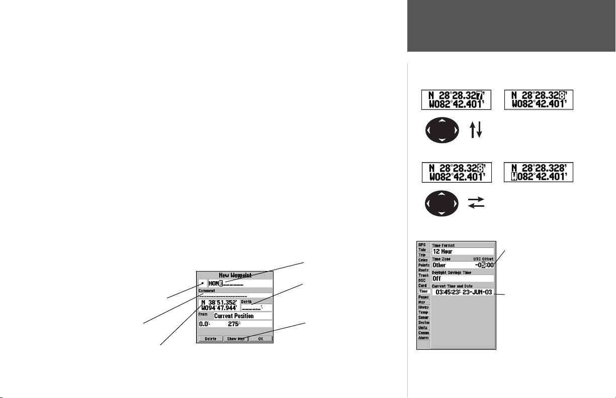
Naming a waypoint or placing any sort of data that has not been predefi ned requires the use of
both the ARROW KEYPAD and the ENTER/MARK key.
To enter a name or number in a data fi eld:
1. Once you have accessed a page with programmable data fi elds (i.e. ‘ Waypoint Edit’) you can use
the ARROW KEYPAD to move the cursor (Highlight) to fi elds on the page. Use the UP/DOWN
arrows to move up or down and the LEFT/RIGHT arrows to move sideways.
2. Pressing the ENTER key with the fi eld highlighted begins the process for entering data in the form
of alphanumeric characters.
3. Use the ARROW KEYPAD UP/DOWN arrows to cycle through numbers 0 to 9, plus/minus symbols,
blank space, and the alphabet. Pressing and releasing the keypad moves you character by character
through the list. Pressing and holding the keypad moves you rapidly through the list.
4. Use the ARROW KEYPAD LEFT/RIGHT arrows to move to the next character on the line or
backwards to edit characters. If there are more than two lines of data, keep pressing to the RIGHT
to drop down to the next line.
5. When data entry is completed press ENTER to accept data, then move to the next programmable
fi eld. Not all data fi elds are programmable, like the date and time. When moving about a page with
these type of fi elds, the cursor will skip over them.
Every fi eld and button on this page
can be programmed or activated.
A waypoint symbol can be selected
from a list of symbols.
The waypoint can be renamed.
A depth can be entered.
Getting Started
Entering Data
Pressing UP or DOWN
on the ARROW KEYPAD
changes numbers and
letters.
Pressing LEFT or RIGHT
on the ARROW KEYPAD
moves the cursor along the
line or to the next line.
Data Entry Field
Non-programable
data fi elds
A comment can be added.
The coordinates can be changed.
Option buttons can be activated.
5
Page 16
Getting Started
Tour/Backlighting
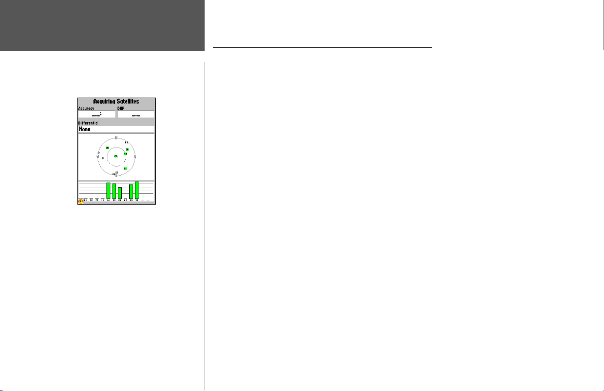
A full-screen GPS Information pop-up page is displayed
after you press the ENTER key to acknowledge the
Warning Page. The pop-up page will go away after the unit
gets a position fi x or you press either ENTER or QUIT.
The page can be disabled and enabled on the Pages Tab
(see page 83).
GPSMAP 188/188C/238 Sounder Getting Started Tour
The Garmin GPSMAP 188/188C/238 Sounder is a powerful electronic navigation system that provides detailed map coverage and convenient control of many advanced features right from the screen
display. This tour is designed to take you through the basic pages and functions of the system using the
simulator mode. Once you’re familiar with the main pages and functions of the unit, refer to the reference section for instructions on performing specifi c tasks and functions.
The Getting Started Tour assumes that the receiver has been properly installed and initialized, and
you have not changed any of the default unit settings. If you have changed any settings (position
formats, units of measure, etc.), the descriptions and pictures in the tour may not match your
confi guration.
After powering on the GPSMAP 188/188C/238 Sounder, the GPS Information Page appears as the
receiver begins acquiring satellites. From this or any other page, you may also adjust the backlighting.
The GPSMAP 188/188C/238 Sounder’s adjustable screen backlighting is controlled with the
POWER key, and may be adjusted at any time from any page. The backlight can cycle through off,
user-defi ned, and maximum backlight levels by repeatedly pressing the POWER key.
To turn on and adjust the backlighting:
1. Press POWER and the Light window appears.
2. Press POWER again and the user-defi ned level of backlighting activates. You may adjust this level
by pressing UP or DOWN on the ARROW KEYPAD. If you press POWER one more time, the back-
lighting will be at the maximum setting.
3. Press ENTER or QUIT when done.
The backlight will now cycle through off, the user-defi ned, and maximum backlight levels by
repeatedly pressing the POWER key.
6
Page 17
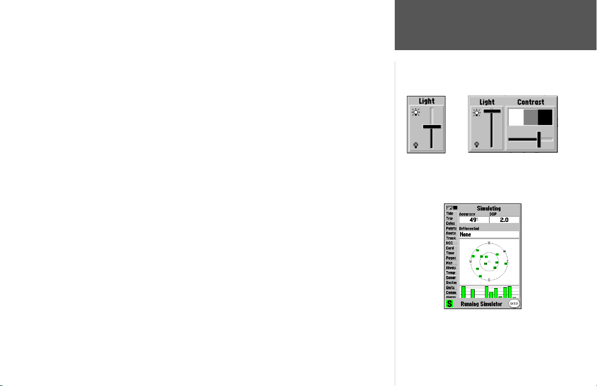
You may also adjust the screen contrast (GPSMAP 188/238 monochrome only).
To adjust the screen contrast:
1. Press POWER and the Light and Contrast window appears.
2. To decrease or increase the screen contrast, press left or right on the ARROW KEYPAD.
3. Press the ENTER/MARK key to fi nish.
Each page of the GPSMAP 188/188C/238 Sounder’s system also features an options page, which
gives you access to other functions and features that relate to the specifi c page you are viewing. To get a
feel for how the option pages work, let’s put the GPSMAP 188/188C/238 Sounder into simulator mode.
To activate the simulator mode:
1. Press the MENU key twice for the Main Menu. Press Up or Down on the ARROW KEYPAD until
the ‘GPS’ tab is highlighted, then press the MENU key once.
2. Use the UP or DOWN arrow of the ARROW KEYPAD to highlight the ‘Start Simulator’ option and
press ENTER. Choose ‘No’ to the retail demonstration and press the ENTER key.
3. Press the ENTER key to confi rm the ‘Running Simulator’ message that appears at the bottom of the
display. ‘Simulating’ appears at the top of the Main pages.
Use the ARROW KEYPAD to move the backlighting slider
UP for brighter or DOWN for dimmer backlighting. Monochrome units will have an additional Contrast adjustment.
While in Simulator mode, a ‘Running Simulator’ message appears after 2 minutes of inactivity..
Now you’re ready to continue the rest of the simulated tour. Keep in mind that the GPSMAP 188/
188C/238 Sounder does not track satellites in simulator mode, and this mode should never
be used for actual navigation. All the waypoint and route planning done in simulator mode is still
retained in memory for future use.
Getting Started
Simulator Mode
A “Running Simulator” message
appears after 2 minutes of
inactivity.
7
Page 18
Getting Started
Main Pages/
Map Page
Main Pages
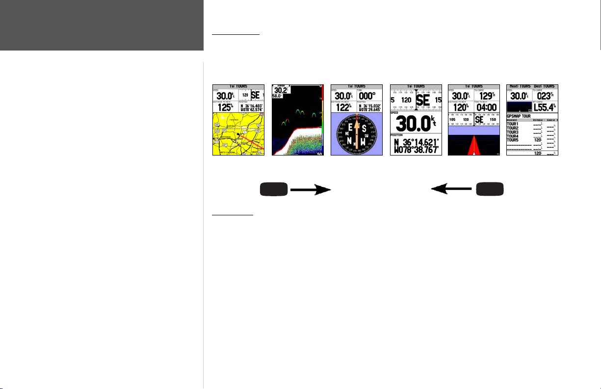
The Map Page is one of six main pages used in the GPSMAP 188/188C/238 Sounder’s system. The
six main pages are the Map Page, Sonar Page, Compass Page, Numbers Page, Highway Page, and Active
Route Page. All six pages are linked together in a simple chain, which allows you to scroll through the
pages in either direction using the PAGE and QUIT keys.
Map Page
Map Page
Sonar Page
PAG E
Compass Page
Numbers Page
Highway Page
QUIT
Active Route Page
The GPSMAP 188/188C/238 Sounder’s Map Page combines digital chartplotting with a user-selectable display of navigation data and a built-in worldwide database. It will also be the page you use most
to create and edit waypoints and routes. Before we take off on our practice route, let’s take a brief look
at its various features and displays.
The map display shows your “boat” as a triangle marker on an electronically generated chart.
Geographic names, roads, markers and buoys that are provided by the optional BlueChart or
MapSource data are also shown. It also displays your track, routes and nearby waypoints. An on-screen
cursor lets you pan to other map areas, determine the range and bearing to a position, and perform
various waypoint and route functions.
The data window, located at the top of the page, provides a user-selectable display of various navigation data, including speed over ground, distance to the next navigation point, compass ribbon, and
8
current position coordinates. The current map scale setting is located at the bottom right of the page.
Page 19
Using the Map Cursor
Working from the Map Page is a simple process that centers around the use of the cursor.
Controlled by the ARROW KEYPAD, the cursor is an important tool that can be used to pan to
other map locations, mark and edit waypoints and routes, and review position data of on-screen map
items and waypoints.
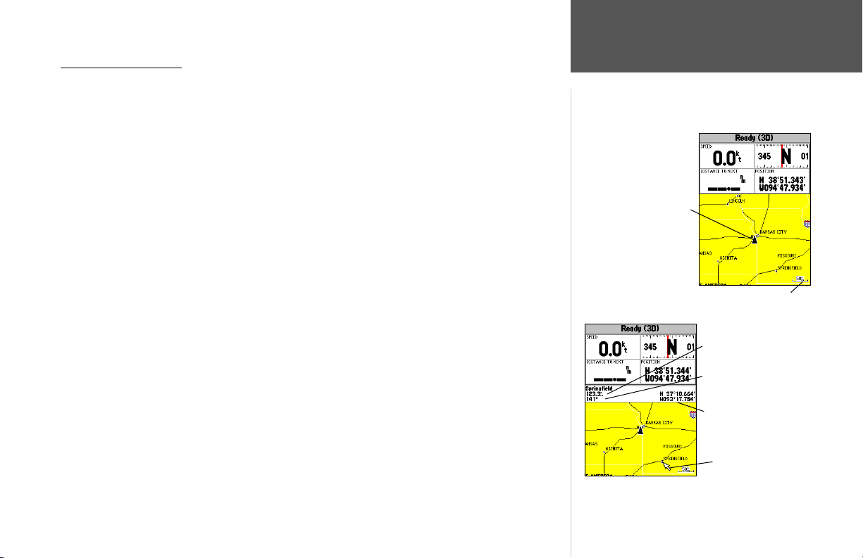
To get a feel for using the Map Page and using the cursor, try the following exercise:
1. Use the IN/OUT keys to set the map scale to the 50 nm setting. Your boat should be near the
center of the map, at the receiver’s last known position. (If your boat isn’t where it should be, make
sure that you have initialized the receiver and acquired a position as described on pages 4-5.)
2. Use the ARROW KEYPAD to move the cursor. Notice how another data fi eld appears, showing
the bearing and distance from your boat to the cursor, along with the latitude/longitude of the
cursor.
3. Press the QUIT key to remove the cursor and re-center your boat on the map display.
As you become more familiar with the cursor, you’ll see that the map display actively scrolls or
‘pans’, letting you explore areas around the world and create waypoints and routes. Wherever you
move the cursor, you’ll always be just one QUIT keystroke away from returning the map to your
present position.
Now that you’ve seen how the Map Page can be used to monitor your present location, let’s take a
minute to learn how to mark and store your present position as a waypoint. Since you’re in simulator
mode, the present position displayed will be the last position calculated by the receiver, which should
be the spot where you’ve initialized the unit. This will also give you an opportunity to see how the
GPSMAP 188/188C/238 Sounder’s keypad and ENTER/MARK key are used for data entry and changing the waypoint name and symbol.
Getting Started
Map Cursor
Current position
Map Scale
Distance
Bearing
Cursor Coordinates
Map Cursor
9
Page 20
Getting Started
Marking Waypoints
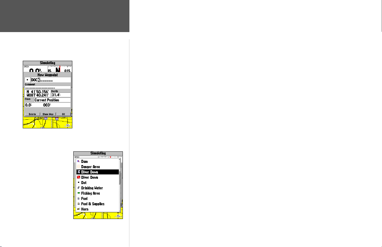
You can choose from a list
of useful symbols.
There are two Diver Down
waypoint symbols to select
from: the International and
U.S. versions.
10
Press ENTER/MARK
after entering the name.
To mark your present position:
1. Hold down the ENTER/MARK key until the ‘New Waypoint’ window appears then release the
key. The window will show a default three-digit waypoint name/number (001), symbol (dot), and
position. You can leave the name as the auto-assigned number, but for this exercise, lets change
the name to ‘DOCK’.
2. Use the ARROW KEYPAD to highlight the waypoint name fi eld (001) and press ENTER/MARK.
You will see that just the fi rst ‘0’ is now highlighted.
3. Press LEFT on the ARROW KEYPAD to clear the name fi eld.
4. Press UP or DOWN on of the ARROW KEYPAD until the letter ‘D’ appears, and then press RIGHT
to go to the next space to the right, then UP or DOWN again until ‘O’ appears. Repeat this until you
have entered the name ‘DOCK’. If you make a mistake and select an incorrect character, simply press
LEFT on the ARROW KEYPAD to backspace the cursor and then UP or DOWN to correct the entry.
(If you accidentally press ENTER/MARK before you are done, simply press ENTER/MARK again
and move the highlight to where you left off.)
5. After you have entered all the letters, press ENTER/MARK to confi rm the name.
6. To access the waypoint symbol page, highlight the waypoint symbol fi eld, which is to the left of the
waypoint’s name and press ENTER/MARK. The default symbol is a dot.
7. You will see an alphabetical list of available waypoint symbols to choose from. Press the ARROW
KEYPAD UP or DOWN until you highlight the ‘ANCHOR’ symbol. You will see a scroll bar on the
right of the window indicating your current position on the entire list of symbols.
8. Press ENTER/MARK to confi rm the ‘ANCHOR’ symbol.
9. Highlight ‘OK’ at the bottom of the window and press ENTER/MARK again to confi rm the ‘OK’
prompt and save the waypoint.
The waypoint is now stored in memory. Note that waypoints may also be created graphically from
the map display or by manually entering position coordinates. Each of these techniques is described in
the reference section of the manual and/or on your GPSMAP 188/188C/238 Sounder Quick Reference
Guide.
Page 21
Going to a Destination
GPS is all about marking positions as waypoints and navigating to them using the receiver’s
steering guidance and map displays. We’ve already seen how to use the ENTER/MARK key to store
your present position, so it’s time to move on to the fun part—going to a destination.
The NAV key, located on the keypad above the QUIT key, is the primary tool used to select a
destination waypoint, TracBack, or a route to navigate. The NAV key can be used in two primary ways:
• Pressing NAV once displays a list of options from which you can select ‘Go To Point’, ‘Follow Route’,
‘Follow Track’, or ‘Stop Navigation’.
• Highlighting an on-screen waypoint or map item as a destination directly from the Map Page and
pressing NAV allows you to graphically select points to “Go To”.
For our simulated trip, you’re going to select a pre-programmed tour route using the fi rst method.
This will also show how the MENU key is used throughout the GPSMAP 188/188C/238 Sounder
system to provide tab style options and functions. Let’s start by changing the position to where the
practice route is located.
To change the GPSMAP 188/188C/238 Sounder position in simulator mode:
1. Press the MENU key twice to display the list of Main Menu tab items.
2. Use the ARROW KEYPAD to highlight the ‘Systm’ tab.
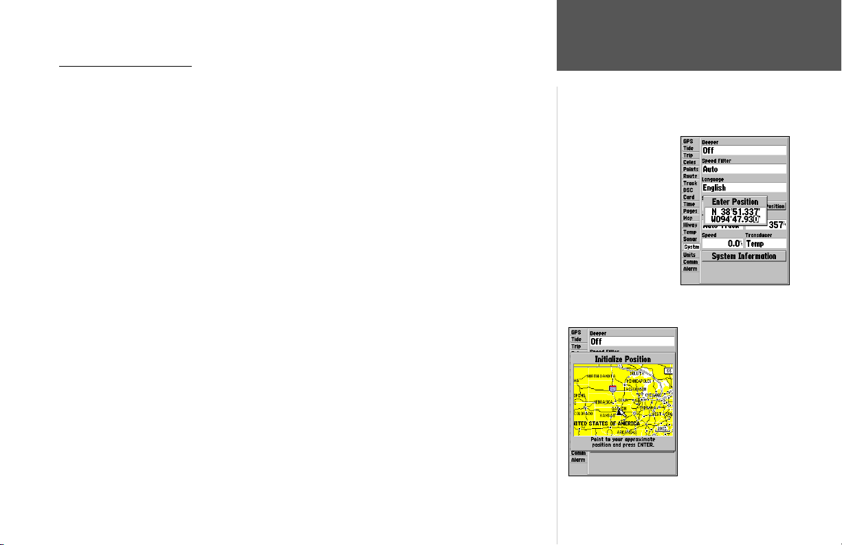
3. Highlight ‘Set Position’ in the simulator setup window and press ENTER.
4. From the Initialize Position page, press the MENU key. With ‘Enter As Text’ highlighted, press
ENTER.
5. On the Enter Position window, press ENTER then use the ARROW KEYPAD to enter N34°56.800’,
W076°24.066’ and press ENTER when done, then press QUIT to return to the Map Page.
Getting Started
Using the NAV Key
Text entry for
simulator position.
For future practice, you
may skip steps 3 through
5 and use the ARROW
KEYPAD to point to a
location from the Initialize
Position page.
11
Page 22
Getting Started
Simulated Tour
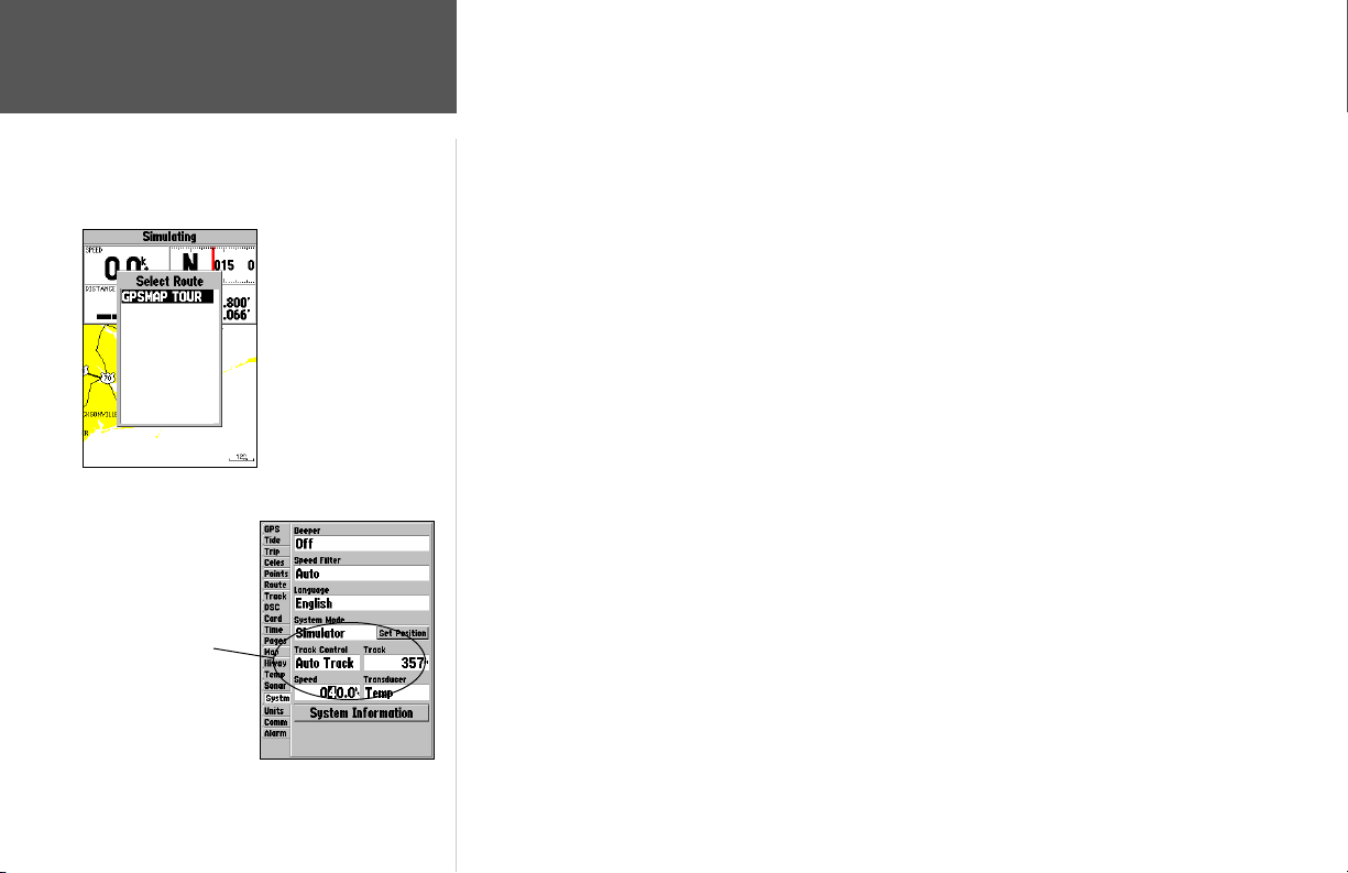
The Set Position, Track
Control, Track and Speed
fi elds will only show while
in simulator mode.
Select the practice route
and press ENTER/MARK.
To activate the practice route stored in memory for navigation:
1. Press NAV. A list of options appear.
2. Use the ARROW KEYPAD to highlight ‘Follow Route’ and press ENTER.
3. The Select Route page appears, with the ‘GPSMAP TOUR’ route highlighted.
4. Press ENTER, highlight ‘Activate’, and press ENTER again to activate the route.
To zoom in to a closer map scale:
1. Repeatedly press the ZOOM IN key until you select the 3 nm scale.
You may also hold the ZOOM IN or ZOOM OUT keys down to quickly scroll through the map
scales. The Map Page should now display fi ve waypoints chained together in a simple route, with your
boat at the fi rst route waypoint.
A data fi eld at the top of the page now displays the speed, distance to the second route waypoint,
your position coordinates and a compass ribbon which shows you which way to go. To get started, let’s
enter a speed for our vessel, which we can do from the Main Menu Page.
To enter a boat speed:
1. Press the MENU key twice to display the Main Menu Page.
2. Use the ARROW KEYPAD to highlight the ‘Systm’ tab, then press RIGHT then DOWN until the fi eld
below the word ‘Speed’ is highlighted and press ENTER.
3. Use the ARROW KEYPAD to enter a speed of 40 knots.
4. Press ENTER to fi nish, and QUIT until you return to the Map Page.
Once a speed has been entered, you’ll notice that the map automatically begins to move slowly,
keeping your boat centered on the display. The direction of movement, also called ‘track’, is controlled
by the simulator.
12
Page 23
You’ll now have a clearer picture of the route you are navigating. Keep in mind that when you
exceed the usable range of the built-in database or the optional MapSource or BlueChart data in use,
the range fi eld displays ‘overzoom’ to indicate that you should exercise extreme caution using the map
data. Press the ZOOM IN key to zoom into the 2 nm scale. Now that you’ve zoomed in a little closer to
your route, you can pan ahead of your vessel with the cursor to review map items and create on-screen
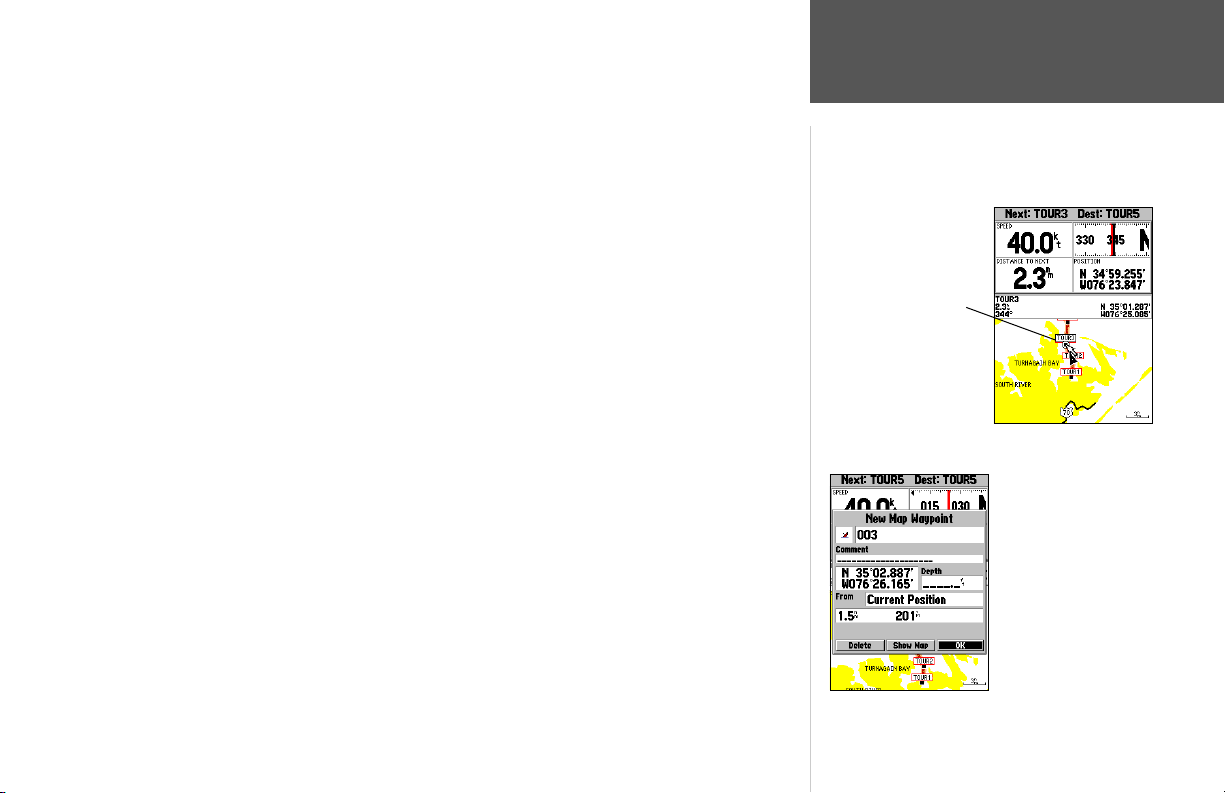
waypoints. Move the cursor to highlight the ‘TOUR3’ waypoint— just use the ARROW KEYPAD to
move the cursor as close as possible to the waypoint (To move the cursor in small increments, try a
series of short key presses).
Once the cursor is over the TOUR3 waypoint, you’ll notice that the waypoint symbol and name
are highlighted. The data fi eld at the top of the page displays the waypoint name, the range and bearing
from your present position, and the coordinates for the waypoint.
To review the waypoint page for a selected waypoint:
1. With the waypoint highlighted, press ENTER.
2. To return to the Map Page, press ENTER again or press QUIT.
The waypoint will ‘highlight’
when the cursor is moved
over it.
The cursor can also be used to create new waypoints right from the map display.
To create a new waypoint using the cursor:
1. Use the ARROW KEYPAD to move the cursor as close as possible to the following position:
N35º 02.914; W 076º 26.152’ (Use the data window to verify the cursor position.)
2. Press and release the ENTER/MARK key to capture the cursor position. Do not hold the button
down, as doing so will mark your present position, not the map position.
3. Use the ARROW KEYPAD to highlight the waypoint symbol fi eld to the left of the waypoint name/
number.
4. Press ENTER to access the symbol page.
5. Use the ARROW KEYPAD to select the ‘Shipwreck’ symbol and press ENTER to confi rm.
6. Highlight ‘OK’ and ENTER again to fi nish.
Getting Started
Reviewing/Creating
Map Waypoints
Creating a new waypoint
with the map cursor.
13
Page 24
Data Fields
Simulated
Fish Arch
Bottom
Whiteline
Thermocline
Outer edge
beam returns
Frequency
mode
14
Getting Started
Sonar Page
Sonar Page
Dual frequency returns
Adjustment
Menu
Depth
Scale
Center beam
return
Flasher
Sonar Page
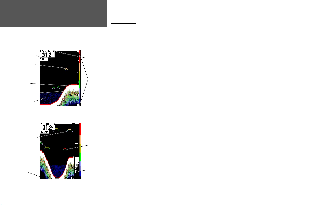
The Sonar Page is where your GPSMAP 188/188C/238 Sounder becomes a powerful fi shfi nder/
fl asher. The top left of the screen contains data fi elds, while the Adjustment Bar above the data fi elds
allows direct access to the settings most commonly changed while using the Sonar Page. The middle
of the page contains a right-to-left moving sonar image of the water beneath your boat (Items appear
as they pass under your transducer. Those items on the right side of the screen are closer to you than
those on the left.). Along the right side of the screen is an adjustable scale which refl ects the depth of
the area being displayed. If the unit does not detect a transducer attached to the unit, a “Sonar Turned
Off” message appears across the Sonar Page. You may also show a sonar fl asher and color bar on the
right side.
The sonar display may also be set to show a split screen view of a zoomed portion of the sonar,
bottom lock (display scaled from the bottom up), or a combination of these options (see pg. 34). For
example, you may choose to show dual frequency at a 2X zoom (Dual 2X) on one half and normal
range dual frequency (Dual) returns on the other half. The current display mode will be displayed at
the bottom of each sonar display.
On color models, sonar returns show as red (strongest), then oranges (strong), yellows (medium),
greens (weaker) and blues (weakest). On grayscale models, stronger returns appear darker and weaker
returns lighter. The ‘ Fish Symbols’ option (see page 38) allows you to view the actual sonar data, a fi sh
symbol, or a combination of both. ‘Fish Symbols’ appear as green. When the unit is set to ‘Dual’ (see
page 35), the appearance of the fi sh symbols (and simulated fi sh returns) will change. Fish symbols
from the narrower beam (200kHz) will be solid (or narrow returns), but the returns from the wider
beam (50kHz) will be hollow (or wide returns). Simulated fi sh icons are displayed in three different
sizes. Actual fi sh returns may not always appear as perfect arches, due to the speed, fi sh orientation,
and/or other conditions.
More on understanding the Sonar Page may be found on pages 111 and in Appendix I.
Page 25
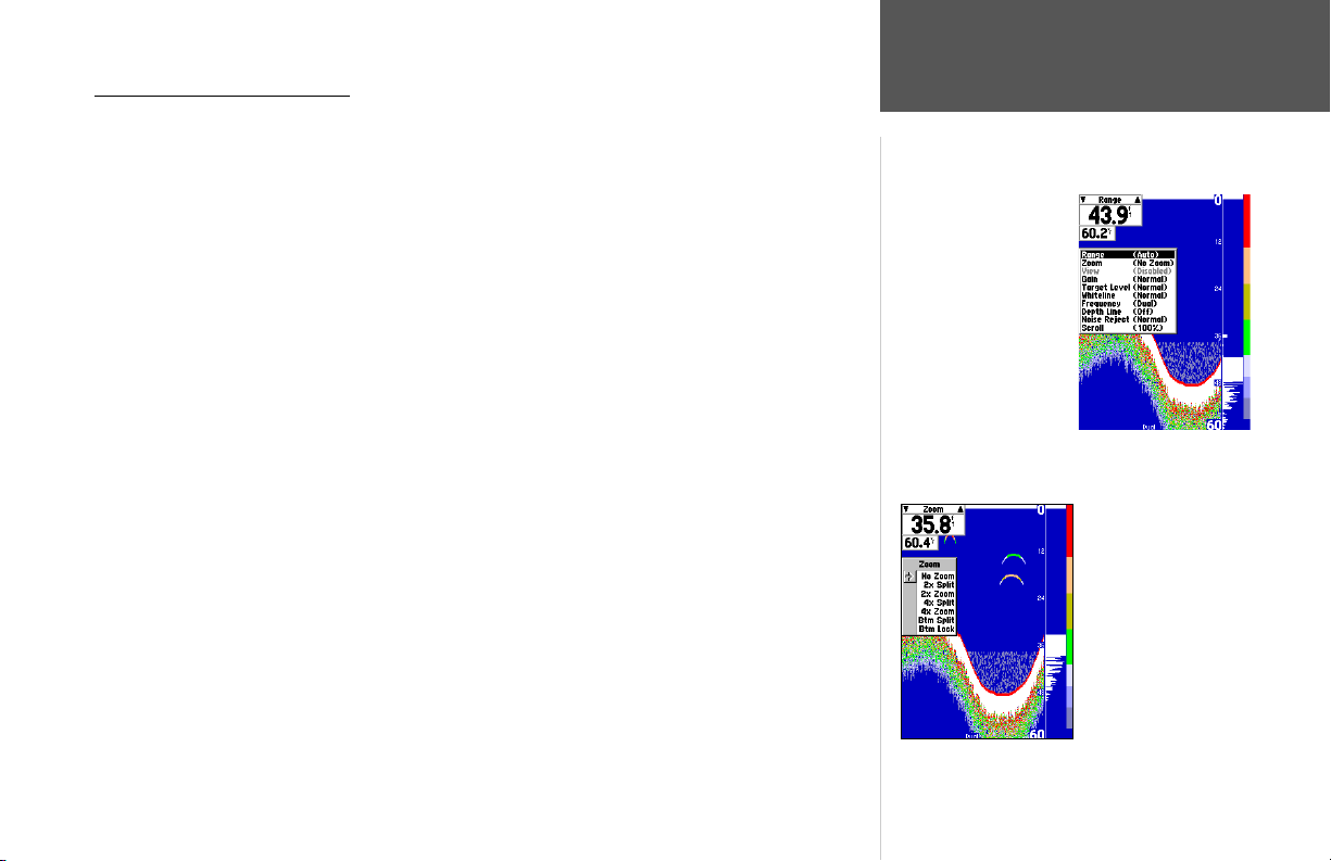
Using the Adjustment Menu
The Adjustment Menu allows direct access to the settings and features most commonly used on
the Sonar Page. There are 10 main adjustment options available: Range, Zoom, View/Span, Gain,
Target Level, Whiteline, Frequency, Depth Line, Noise Reject, and Scroll. The currently selected option
appears in the upper left of the display with up and down arrows on either side of the option name.
To select an adjustment option from the Sonar Page:
1. Press the ARROW KEYPAD LEFT/RIGHT to scroll through the options in the upper left of the
display, then press ENTER to access the desired option’s adjustment window.
OR:
1. Press MENU, highlight ‘Adjustments’ and press ENTER. A list of all options and their current settings appears, with the selected option highlighted. Press UP/DOWN on the ARROW KEYPAD to
select the desired option and press ENTER to access the adjustment window.
To easily exit any of the adjustment options, press the QUIT key.
To change an Adjustment Menu setting:
1. Select an adjustment option to change using one of the two methods described above. The adjustment window will automatically timeout and disappear when idle for 20 seconds.
2. Press the ARROW KEYPAD UP/DOWN to place the pointer or setting bar at the desired setting,
range or percentage (Off, 1-100%).
3. Press ENTER or QUIT to exit the adjustment window; or press LEFT/RIGHT on the ARROW
KEYPAD to view another adjustment window.
To change a setting back to ‘Normal’ or ‘Auto’:
1. On the adjustment window for the desired option, press MENU.
2. Select the desired setting and press ENTER.
For detailed information on the functions and options of the Sonar Page, see pages 33-39. To learn
more about how sonar works, see Appendix I.
Getting Started
Sonar Page
Press MENU, highlight
‘Adjustments’ and press
ENTER to see a list of all
options and their current
settings.
Zoom adjustment options
15
Page 26
Current
Destination
Data
Fields
Getting Started
Compass Page/
Numbers Page
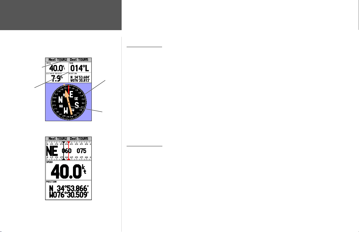
Compass Page
Compass
Ring
Pointer
Arrow
Now that we’re navigating to an actual destination, let’s move on to the GPSMAP 188/188C/238
Sounder’s navigation pages by pressing the PAGE key.
Compass Page
The Compass Page provides graphic steering guidance to a destination waypoint, with an emphasis
on the bearing to your destination and current direction of travel. The middle of the page features a
rotating ‘compass ring’ that shows your course over ground (track) while you’re moving, and a bearing
pointer that indicates the direction of the destination (bearing) relative to the course over ground.
The compass ring and pointer arrow work independently to show—at a glance—the direction of your
movement and the direction to your destination. For instance, if the arrow points up, you are going
directly to the waypoint. If the arrow points any direction other than up, turn toward the arrow until it
points up—then continue in that direction.
The current speed, distance to the next waypoint, turn angle, and current position are displayed at
the top of the screen. This page provides better steering guidance when travelling at slower speeds and/
or when making frequent directional changes. When you are not navigating to a waypoint, the compass
will show your direction of travel as you move but the arrow will not appear.
Numbers Page
Press PAGE to see the next page appearing in the main sequence, the Numbers Page. The
Numbers Page allows for precision navigation to 1 degree of steerage. The default page displays 3 large
numbers fi elds. You may customize the Numbers Page to display the size and number of fi elds along
with the type data you wish to see. (See pages 26-28 for changing the types of data.)
16
Numbers Page
Page 27
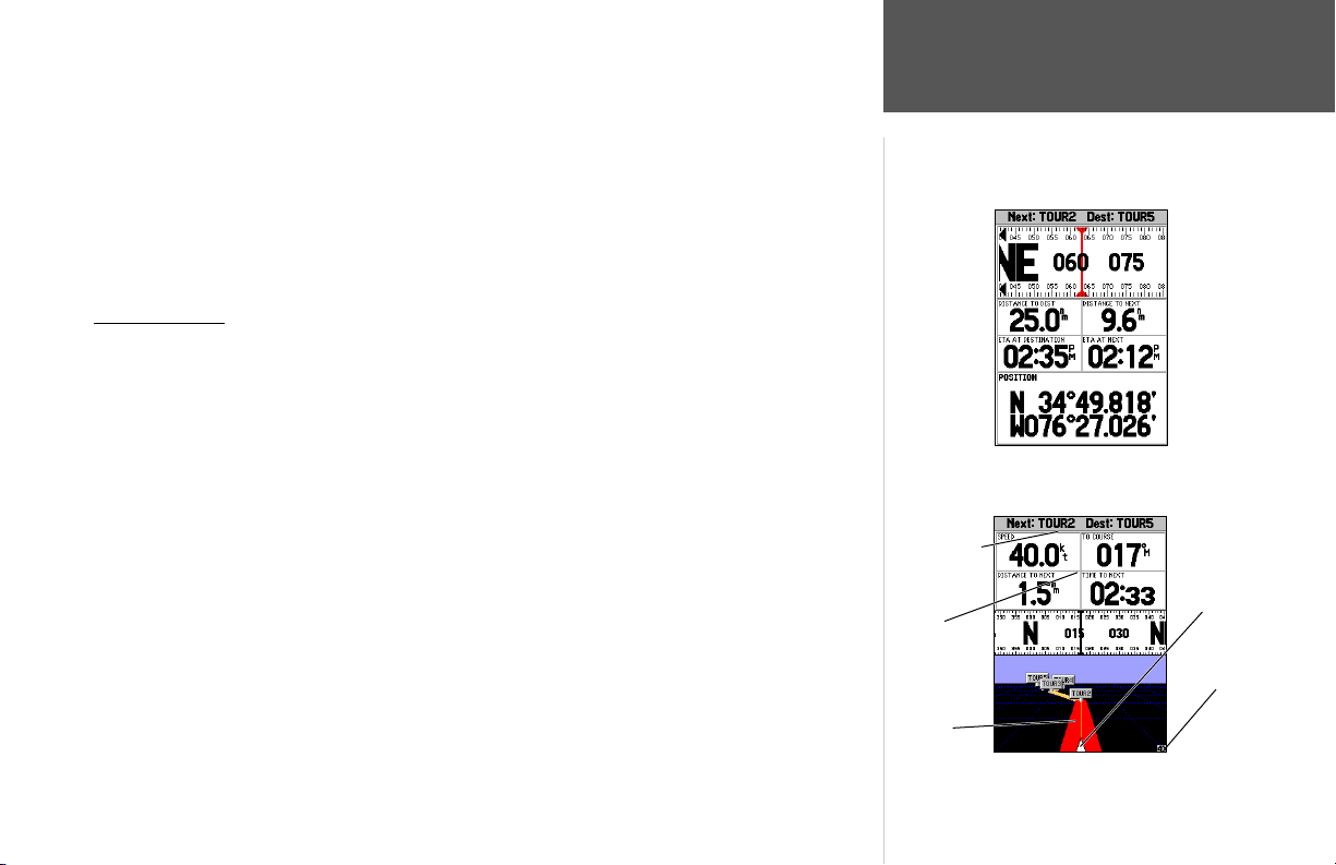
To split the data fi elds:
1. Press MENU, then press ENTER. Highlight the ‘SPEED’ data fi eld and press MENU.
2. Highlight ‘Split Numbers’, then press ENTER. You will now see four new data fi elds. Press QUIT
when done.
3. To return to the original confi guration, repeat the above steps, but instead of ‘Split Number’,
select either ‘Merge Numbers’ or ‘Defaults’. Press QUIT when done.
Let’s move on to the Highway Page by pressing the PAGE key.
Highway Page
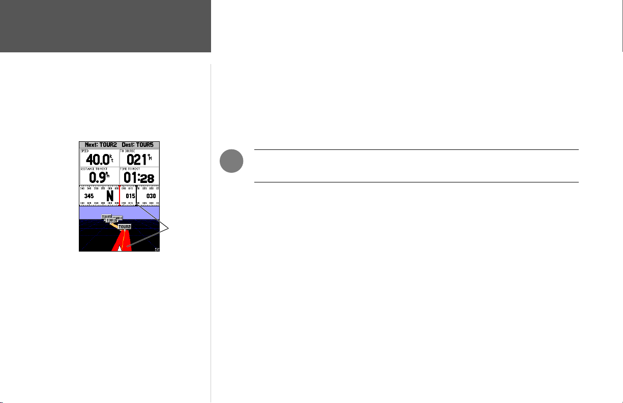
The GPSMAP 188/188C/238 Sounder’s Highway Page also provides graphic steering guidance to
a destination waypoint, placing greater emphasis on the straight-line desired course and the distance
and direction you are off course. As you head toward your destination, the middle of the screen
provides visual guidance to your waypoint on a moving graphic “highway.” Your present position
is at the bottom center of the highway display. The line down the middle of the highway represents
your desired course.
As you navigate toward a waypoint, the highway will actually move, indicating the direction
you’re off course. To stay on course, simply steer toward the center of the highway or “keep it on
the road”. The four default data fi elds at the top of the page indicate ‘Speed’ and ‘Distance To Next’
point, along with ‘To Course’ which shows the bearing to get you back on course and ‘Time To Next’
point. Additionally, a compass ribbon is displayed to show your current heading along with a dark,
vertical bar which will indicate the direct bearing to the navigation point. When the red, vertical
indicator lines up with the black bar in the middle, you are heading directly to the navigation point.
Use the Highway Page as your primary navigation page (in lieu of the Compass Page) when your
main concern is following a defi ned course.
Current
Destination
Data
Fields
Desired
Course
Getting Started
Numbers Page/
Highway Page
Numbers Page with split numbers
Present
Position
Zoom
Scale
Highway Page
17
Page 28
Getting Started
Highway Page
Whenever the GPSMAP 188/188C/238 Sounder is in simulator mode, you can also adjust your
speed and course from the Highway Page using the ARROW KEYPAD. As you head toward each
waypoint in the tour route, try adjusting your boat speed and course to get a feel for how the highway
works.
To adjust the simulated boat speed/heading from the Highway Page:
1. Press the UP arrow of the ARROW KEYPAD to increase the speed in 10 knot/kph/mph increments.
Press the DOWN arrow to decrease the speed in the same increments. Press the LEFT and RIGHT
arrows of the ARROW KEYPAD to steer the boat (adjust the heading).
Steer towards the center of the highway or towards
the black vertical bar on the compass ribbon to get
back on course.
18
)
on course. You can zoom in or out on the Highway display for a smaller or larger view. Five available
settings range from 1X to 16X, with a default setting of 8X. The current scale appears in the bottom
right of the display.
NOTE: In simulator mode, you may also change the simulated speed by pressing UP or
DOWN on the ARROW KEYPAD from the Compass page.
Notice that as you get off course, the highway will move to give you graphic guidance to get back
To zoom in or out on the highway display:
1. Press either the IN or OUT key to increase or decrease the zoom scale.
Page 29
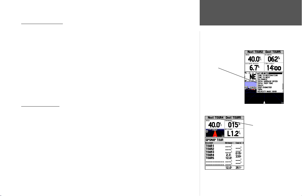
Changing Data Fields
The data fi elds on the main pages may also be confi gured to display several different information
categories (see pages 26-27 for the complete list). On the Highway Page, let’s change the ‘TIME TO
NEXT’ fi eld to ‘TIME OF DAY’.
To change a data fi eld:
1. Press the MENU key to display the Highway Page options.
2. With ‘Change Numbers’ highlighted, press ENTER.
3. Use the ARROW KEYPAD to highlight ‘TIME TO NEXT’, then press ENTER.
4. On the alphabetical list of options, use the ARROW KEYPAD to highlight ‘TIME OF DAY’ and press
ENTER. (You will see a scroll bar on the right side of the window indicating your current
position on the entire list of options.)
5. Press QUIT when fi nished.
Active Route Page
Press PAGE to see the last page appearing in the main sequence, which is the Active Route Page.
Whenever you have activated a route or Follow Track, this page lists the names of the route points
along with useful data for each point. As you navigate the route, the information will automatically
update to indicate the next point along the route. For more detailed information on the Active Route
Page, see page 64.
Getting Started
Changing Data Fields/
Active Route Page
You may choose from
several different types
of data
Current waypoint
Active Route Page
19
Page 30
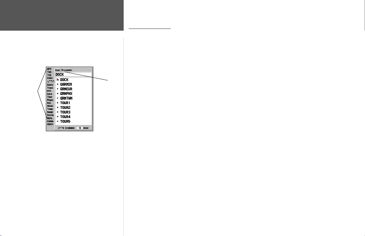
Main
Menu
Tabs
Getting Started
Main Menu Page/
Deleting Waypoints
Main Menu
Submenu
Tabs
Main Menu Page
As you’ve seen, the primary pages provide map and navigation information. The tour’s last page is
the Main Menu page, which allows access to the GPSMAP 188/188C/238 Sounder’s waypoint, route, and
planning functions, as well as various operational and navigation setup features, and celestial and tide
data.
The Main Menu is available from any page, and is accessed through the MENU key.
To access the main menu page:
1. Press the MENU key twice.
The Main Menu page lists 19 vertical ‘tabs’ that are divided into categories by function. You can
view a particular menu by simply highlighting the desired tab, which will then show any secondary
(horizontal) submenu tabs and options for that tab.
To get a basic feel for how the Main Menu page works, let’s delete the two waypoints you created
during the simulated tour. This will ensure that you have a clean slate once you start navigating in your
home waters.
To delete the practice waypoints:
1. Use the ARROW KEYPAD to highlight the ‘Points’ menu tab. You will see a list of stored waypoints
appear to the right of the Main Menu list.
2. Press RIGHT one time on the ARROW KEYPAD to highlight the ‘User’ tab.
3. Press DOWN on the ARROW KEYPAD and highlight waypoint ‘001’ with the shipwreck symbol.
4. You may delete the waypoint by either pressing MENU, then highlighting ‘Delete Waypoint’; or by
pressing ENTER and then highlighting ‘Delete’ from the Waypoint Edit page.
5. Press ENTER to delete the waypoint, then ENTER again to confi rm. Repeat the above steps to
delete the ‘Dock’ waypoint also.
20
Page 31

Congratulations! You’ve now gone through the basic operation of the Garmin GPSMAP 188/188C/
238 Sounder. Your new digital chartplotter is a powerful tool with many advanced features not covered
in the Getting Started tour. For detailed instructions on using these features or performing a specifi c
task, please refer to the Quick Reference Guide or the appropriate reference section of this manual. The
unit is still in Simulator mode for practice, but automatically returns to it’s ‘Normal’ operation mode
when you shut it off and turn it back on.
To turn the GPSMAP 188/188C/238 Sounder off:
1. Press and hold the POWER key for about 2 seconds, until the screen is blank.
2. When the screen is blank, release the POWER key.
The next section of the manual describes the pages and functions of the GPSMAP 188/188C/238
Sounder in detail. If you are unable to locate a specifi c option or function, please refer to the Index on
pages 118-120. Thank you for choosing the Garmin GPSMAP 188/188C/238 Sounder navigation unit.
We hope it will be a useful and fun tool for you wherever you go!
Getting Started
Powering Off Unit
21
Page 32
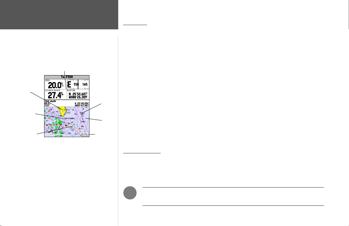
Reference
Map Page
Data Fields
Land
Geographic
Name
Navaids
Map Page (shown in cursor mode and using
optional MapSource data).
Cursor
Water
Map Scale
Map Page
The GPSMAP 188/188C/238 Sounder’s Map Page provides a comprehensive display of electronic
cartography, plotting and navigational data. When using the unit with the optional BlueChart data or
MapSource software, the map display shows your boat on a digital chart, complete with geographic
names, map items, navaids, and a host of other chart features. It also plots your track and displays
any routes and waypoints you create. An on-screen cursor lets you pan and scroll to other map areas,
determine the distance and bearing to a position, and perform various route and waypoint functions.
The ZOOM IN and ZOOM OUT keys, combined with the ARROW KEYPAD, let you select
zoom ranges and move the cursor. The map scale displays at the bottom right of the page.
Two basic map operating modes, position mode and cursor mode, determine what cartography is
shown on the map display. Position mode pans the cartography to keep the present position marker
(triangle) within the display area, while cursor mode pans the cartography to keep the cursor (arrow
pointer) within the display area. The GPSMAP system will always power up in position mode, with
your vessel centered on the map display. When the ARROW KEYPAD is pressed, the GPSMAP 188/
188C/238 Sounder will enter cursor mode.
When the cursor is active, an additional data window appears below the data fi elds to indicate the
position, range and bearing to the cursor or a selected waypoint or map item.
Using the Cursor
The cursor allows you to pan away from your present position and scroll to other map areas
around the world. As you pan past the edge of the current map display, the screen actively scrolls
forward to provide continuous map coverage Keep in mind that the boat icon (triangle marker) moves
with the scrolling map, and may not be visible on the display screen.
22
)
NOTE: When the cursor reaches the edge of the map, the unit map pause as it load
new data.
Page 33
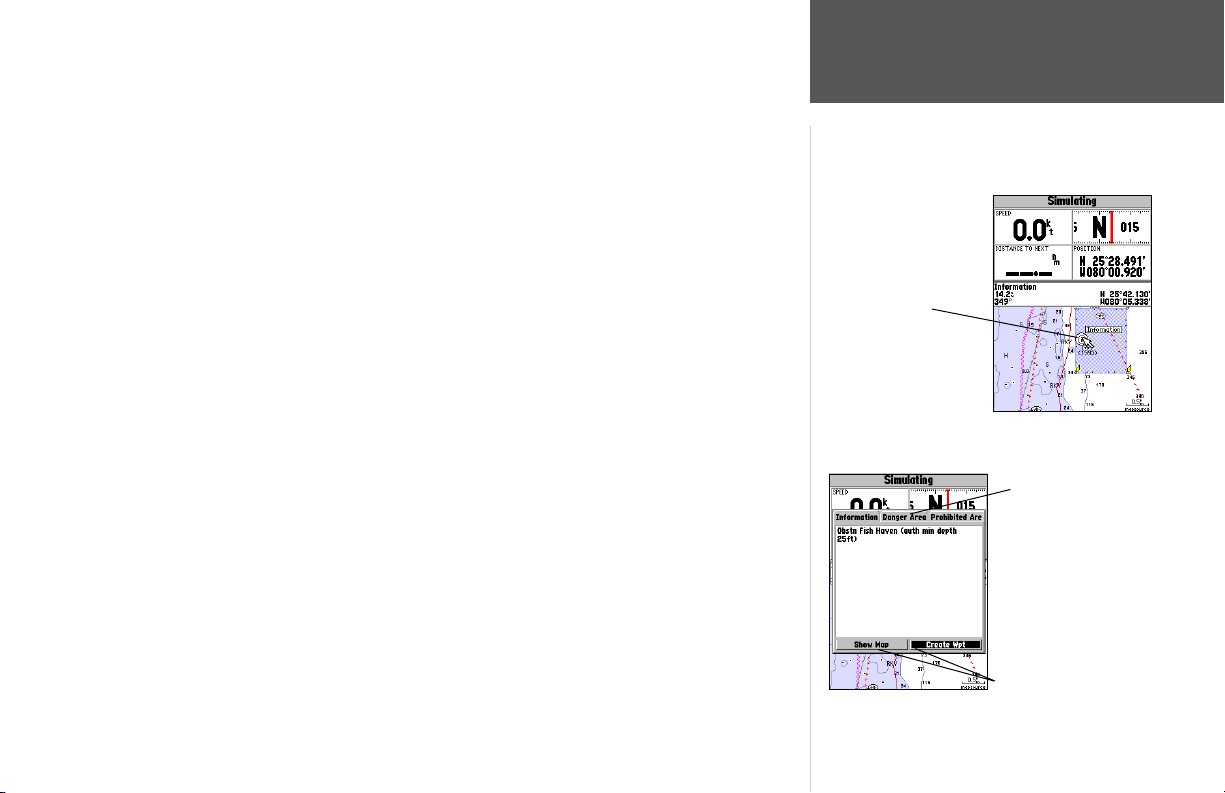
To activate and move the cursor:
1. Press the ARROW KEYPAD in an UP, DOWN, LEFT or RIGHT direction.
As you move the cursor, the distance and bearing from your present position to the cursor aredisplayed in the data window, along with the cursor’s position coordinates. When you zoom in cursor
mode, the cursor is centered on the screen. When the cursor is stationary, a fi xed coordinate position
appears in the position fi eld, and the distance and bearing from your present position changes as your
boat moves.
To eliminate the cursor and re-center your position on the screen:
1. Press the QUIT key. The GPSMAP 188/188C/238 returns to position mode.
The cursor may also be used to “snap-to” on-screen waypoints and map items, allowing you to
review details about a selected position directly from the map display.
To select an on-screen waypoint or map item with the cursor:
1. Use the ARROW KEYPAD to move the cursor to the desired waypoint or map item. If there are
several items grouped closely together, zoom IN closer for a better view.
2. When a waypoint or map item is selected, it is highlighted on the screen, with the name and position displayed.
To view additional details about an on-screen waypoint or map item:
1. With the desired item highlighted , press ENTER.
2. If the symbol is a waypoint, the Waypoint Review page appears, allowing you to review and edit the
properties of the selected waypoint (see pages 48-49 for more information on the Waypoint Review
page).
If the item is a map feature, an Information page appears, showing details about the map item.
With many map items, additional information tabs appears. Use the ARROW KEYPAD to highlight
the individual tabs to display additional details and options.
Reference
Map Page Cursor
Move the cursor over
an item on the map to
highlight it.
Additional information
tabs.
Pressing ENTER while
highlighting a map item
will bring up additional
details and options.
Option buttons
23
Page 34
Reference
Map Page: Cursor
and Zooming
Creating a New Map Waypoint
Using Built-In Basemap
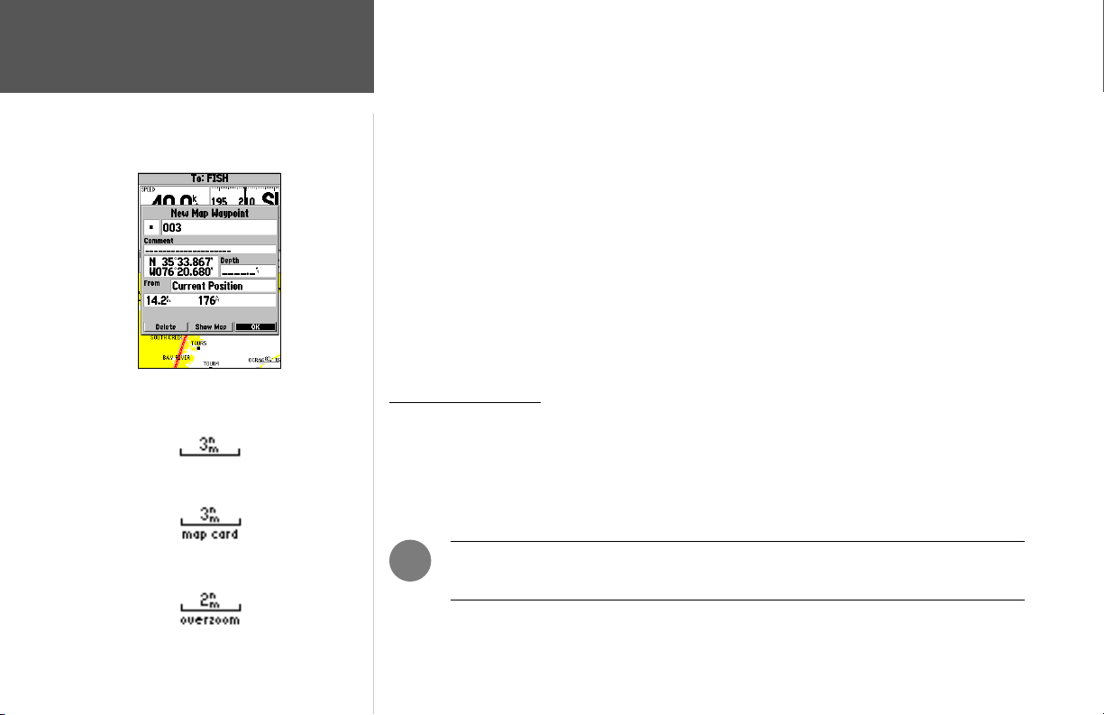
The cursor may also be used to create new waypoints directly from the map.
To create a waypoint with the cursor on an open map location:
1. Use the ARROW KEYPAD to move the cursor to the desired map position.
2. Press and quickly release the ENTER key to capture the cursor location (pressing and holding the
ENTER key captures the current location, not the cursor location).
3. The ‘New Map Waypoint’ window appears. With ‘OK’ highlighted, press ENTER to save the new
waypoint using the default 3-digit name and symbol.
To create a waypoint with the cursor on a map item:
1. Use the ARROW KEYPAD to move the cursor and highlight the desired map feature.
2. Press ENTER to capture the cursor location. The Information page for that feature appears. Use the
ARROW KEYPAD to highlight ‘Create Wpt’ and press ENTER.
3. The New Waypoint window appears. With ‘OK’ highlighted, press ENTER to confi rm the new
waypoint using the default name and symbol based on the map feature.
Selecting Map Scales
The map display has 28 available range scales from 20 ft. to 800 mi. (5 m to 1200 km). The map
scale is controlled by the IN and OUT keys, with the current scale displayed at the bottom right of the
data window.
To select a map scale:
1. Press the OUT key to zoom out and the IN key to zoom in.
24
Using BlueChart/MapSource Data
Overzoom, no additional data
)
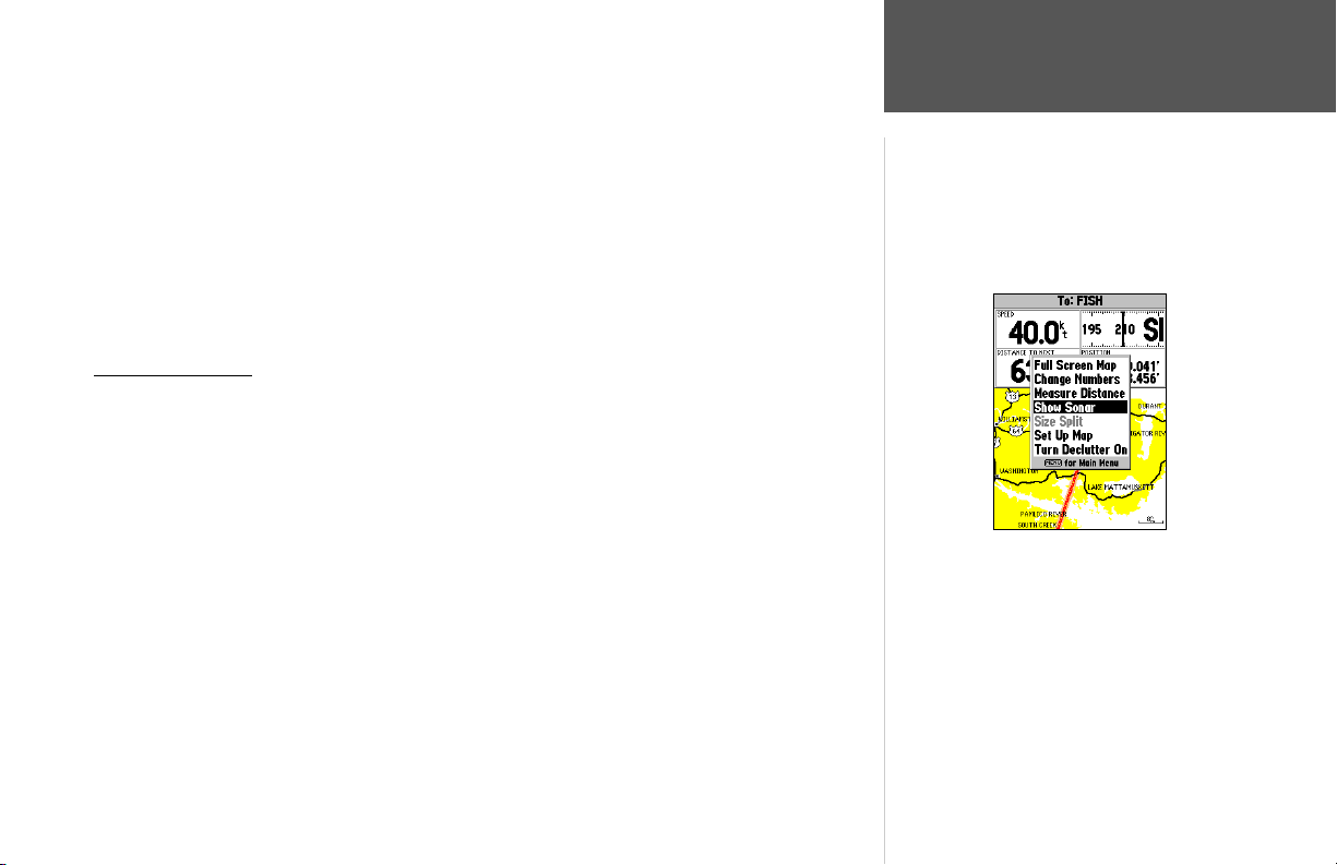
NOTE: The scale value represents the distance from one end of the scale bar to the
other.
Page 35
The GPSMAP 188/188C/238 Sounder’s system has a built-in worldwide database to 20 mi, with
more detailed coverage available through the use of the optional BlueChart or MapSource data. The
GPSMAP 188/188C/238 Sounder displays cartography as long as there is chart information available
for the range you’ve selected. Map coverage will conform to the following conditions:
• When the selected zoom range is covered by either the internal database, BlueChart, or MapSource
data, cartography will be displayed.
• When the selected zoom range is covered by both the internal database and BlueChart/MapSource
data, cartography will be displayed using the data with the best resolution.
• When the selected zoom range exceeds the resolution of the data in use, overzoom cartography will
be displayed and an ‘overzoom’ warning appears below the scale fi eld.
Map Page Options
Many features of the GPSMAP 188/188C/238 Sounder are menu driven. Each of the main pages
has an options menu, allowing you to custom tailor the corresponding page to your preferences and/or
select special features that specifi cally relate to that page. The data window, located at the top of the
main pages provides a user-selectable layout of various types of useful data or sonar information. Each
data fi eld may be confi gured to display any one of several data options. The data window layout may
also be changed to display additional data fi elds and change the actual size of the data displayed. The
GPSMAP 188/188C/238 Sounder’s Map Page provides access to functions and features relating to the
Map Page and the layout options.
To select an option on the Map Page:
1. Press MENU.
2. Use the ARROW KEYPAD to highlight the desired option and press ENTER.
The available options on the Map Page are: Full Screen Map/Show Data, Change Numbers,
Measure Distance, Show Sonar/Show Numbers, Size Split, Set Up Map, and Turn Declutter On/Turn
Declutter Off. Following are details on using each of these options.
Reference
Map Page Options
Map Page Options (with Numbers shown)
25
Page 36
Reference
Map Page Options
Full Screen Map (with BlueChart data)
26
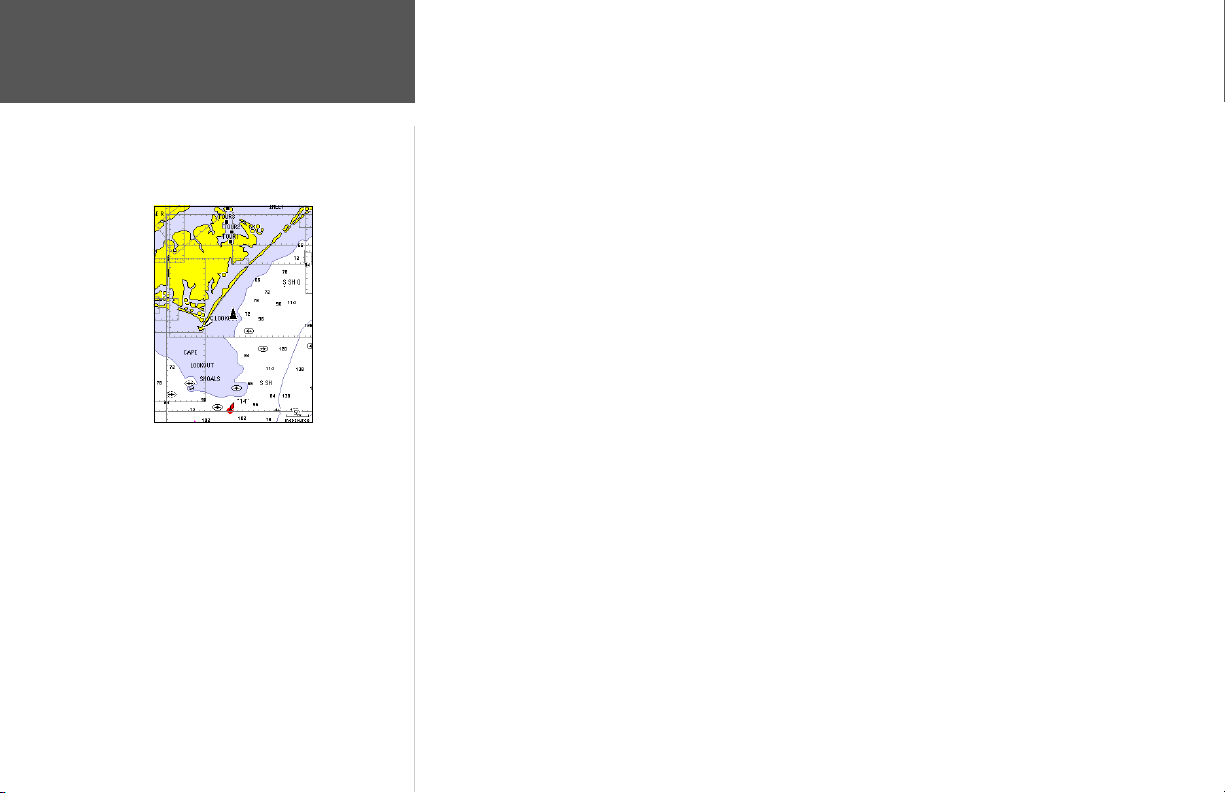
• Full Screen Map/Show Data — toggles between a full screen map or a map with sonar information
and/or data fi elds on the top half of the display. This allows for quick viewing of a full screen map.
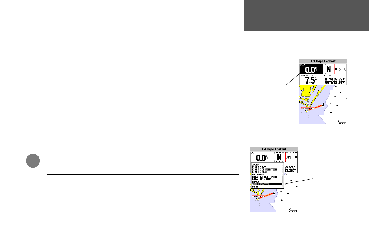
• Change Numbers — allows you to specify the type of data displayed in each data fi eld used on the
map display. This option is available from any of the main pages.
To change a data fi eld:
1. From the menu, use the ARROW KEYPAD to highlight the ‘Change Numbers’ option and press
ENTER.
2. Move the fi eld highlight to the data fi eld you want to change and press ENTER.
3. Move up or down on the list using the ARROW KEYPAD to highlight the data you want to display,
and press ENTER. To exit, press QUIT.
The following options are available for display in data fi elds on the main pages:
• BEARING – Compass direction from your position to destination
• COMPASS – Compass ribbon
• COURSE – Desired Track
• DEPTH – Depth below transducer
• DISTANCE TO DESTINATION – Distance to fi nal waypoint
• DISTANCE TO NEXT – Distance to next waypoint
• ELEVATION – Altitude above/below MSL (Mean Sea Level)
• ETA AT DESTINATION – Estimated Time of Arrival to fi nal waypoint
• ETA AT NEXT – Estimated Time of Arrival to next waypoint
• GPS ACCURACY – Shows estimated GPS accuracy
• HIGHWAY – Smaller version of the Highway Page
• MAXIMUM SPEED – Fastest speed the unit has traveled
• MOVE AVERAGE SPEED – Average moving speed
• MOVE TRIP TIME – Time unit has been moving for a trip
• OFF COURSE – Distance from desired track
Page 37
• POINTER – Arrow points to your destination
• POSITION – Current position coordinates
• SONAR – Compressed view of sonar data
• SPEED – Speed over ground
• TIME OF DAY – Current time
• TIME TO DESTINATION – Time to fi nal waypoint
• TIME TO NEXT – Time to next waypoint
• TO COURSE – Bearing to desired track
• TOTAL AVERAGE SPEED – Total average speed
• TOTAL TRIP TIME – Total travel time of trip, stopped and moving
• TRACK – Current compass direction of travel
• TRIP ODOMETER – Trip Odometer
• TURN – Directional amount of turn needed to match bearing
• VELOCITY MADE GOOD – Velocity Made Good to destination
• VOLTAGE – Current voltage reading being received by unit
• WATER SPEED – Speed through the water (if equipped with optional speed transducer/sensor)
• WATER TEMP. LOG – Smaller version of the Temperature Log (if equipped with temperature transducer/
sensor)
• WATER TEMPERATURE – Water temperature (if equipped with temperature transducer/sensor)
Reference
Map Page Options
Highlight the fi eld you
wish to change
)
NOTE: COMPASS, HIGHWAY and POSITION will only be available on medium and large
sized data fi elds.
Choose the type of data
you wish to display.
27
Page 38
Distance and
Bearing
Cursor
Coordinates
Map Cursor
28
Reference
Map Page Options
Single, large data fi eld
Default, medium fi elds
Split, small fi elds
Full screen map shown
(with BlueChart data)
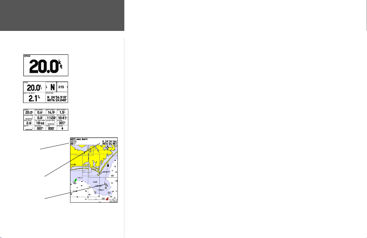
You may also choose to ‘merge’ the four medium, default data fi elds to a single, large fi eld for better
readability, or ‘split’ any or all of the default data fi elds to show 4 small data fi elds. This option is available from any of the main pages with the exception of the Numbers Page. One the Numbers Page, you
may split each of the 3 large data fi elds into 4 medium fi elds, for a total of 12 data fi elds.
To split or merge the Numbers fi elds:
1. While in ‘Change Numbers’ mode, highlight the data fi eld you want to change and press MENU.
2. Choose ‘Split Number’ or ‘Merge Numbers’, then press ENTER. You will now see four new data
fi elds or one large fi eld. Press QUIT when done.
3. To return to the factory confi guration, repeat the above steps, but instead choose ‘Defaults’, then
press ENTER. Press QUIT when done.
• Measure Distance — allows you to measure the bearing and distance between any two points on
the map display.
To measure the bearing/distance between two points:
1. Highlight the ‘Measure Distance’ option and press ENTER. An on-screen pointer appears on the
map display at your present position with ‘ENT REF’ below it.
2. Move the cursor to the desired reference point (the point that you want to start measuring from)
and press ENTER.
3. Mov
e the cursor to the point that you want to measure to. The bearing and distance from the
reference point, will be displayed in the data window below the data fi elds, along with the cursor’s
coordinates. Press the QUIT key to fi nish.
• Show Sonar/Show Numbers — toggles between a Map Page with Sonar information on the top
portion, or a Map Page with data fi elds on the top of the display.
To show sonar or show data fi elds:
1. Highlight either the ‘Show Sonar’ or ‘Show Numbers’ option and press ENTER. The Map Page will
now be split with sonar and depth information or data fi elds showing on the top.
Page 39
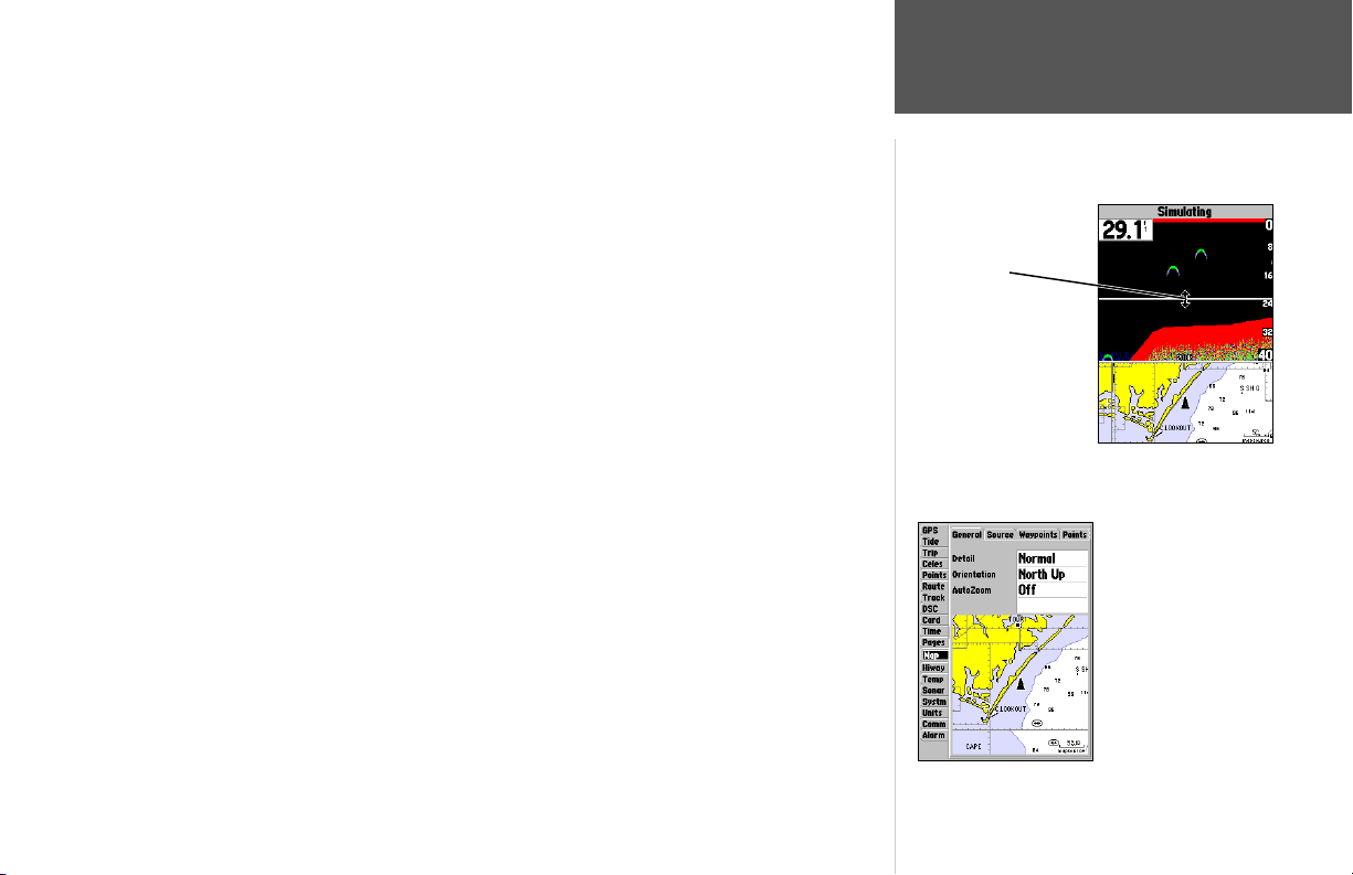
• Size Split — enables height adjustment of the Map Page sonar split screen. You may adjust the size
of the map/sonar split window anywhere from 1/3 to 2/3 height from the top of the screen. You must
be showing sonar information to use this option.
To resize the Map Page sonar split screen:
1. From the Map Page split screen, press MENU.
2. Highlight ‘Size Split’ and press ENTER.
3. Use the ARROW KEYPAD to move the vertical double-arrow UP or DOWN until the desired
horizontal height line shows, then press ENTER.
• Set Up Map — jumps to the Map tab of the Main Menu, allowing you to confi gure the map display
to your preferences, including map detail, map orientation, automatic zoom, and various map items
Double-Arrow
Adjusting the split map/
and points. The map set up option uses a ‘fi le tab’ feature, making it easier to organize the various
settings for ease of use. The following lists the settings available under each tab:
General Detail, Orientation, AutoZoom
Source Basemap, Data Card Maps
Waypoints Waypoints, Active Route
Points Spot Soundings, Tide Stations, Services
Navaids Symbol Set, Text Size, Light Sectors
Nav Line Heading Line, Bearing Line, Course Line
Track Saved Tracks, Track Log
Other Accuracy Circle, Lat/Lon Grid, Map Outlines
To change a map setup feature:
1. From the Map Page menu, highlight ‘Set Up Map’ and press ENTER.
2. Move LEFT or RIGHT on the ARROW KEYPAD to highlight the desired tab, then UP or DOWN on
the ARROW KEYPAD to highlight to the setting you want to change and press ENTER.
3. Move UP or DOWN on the ARROW KEYPAD to highlight to the desired setting and press ENTER.
To exit, press QUIT.
Reference
Map Page Options
sonar display
Main Menu—
Map Confi guration Tab
29
Page 40
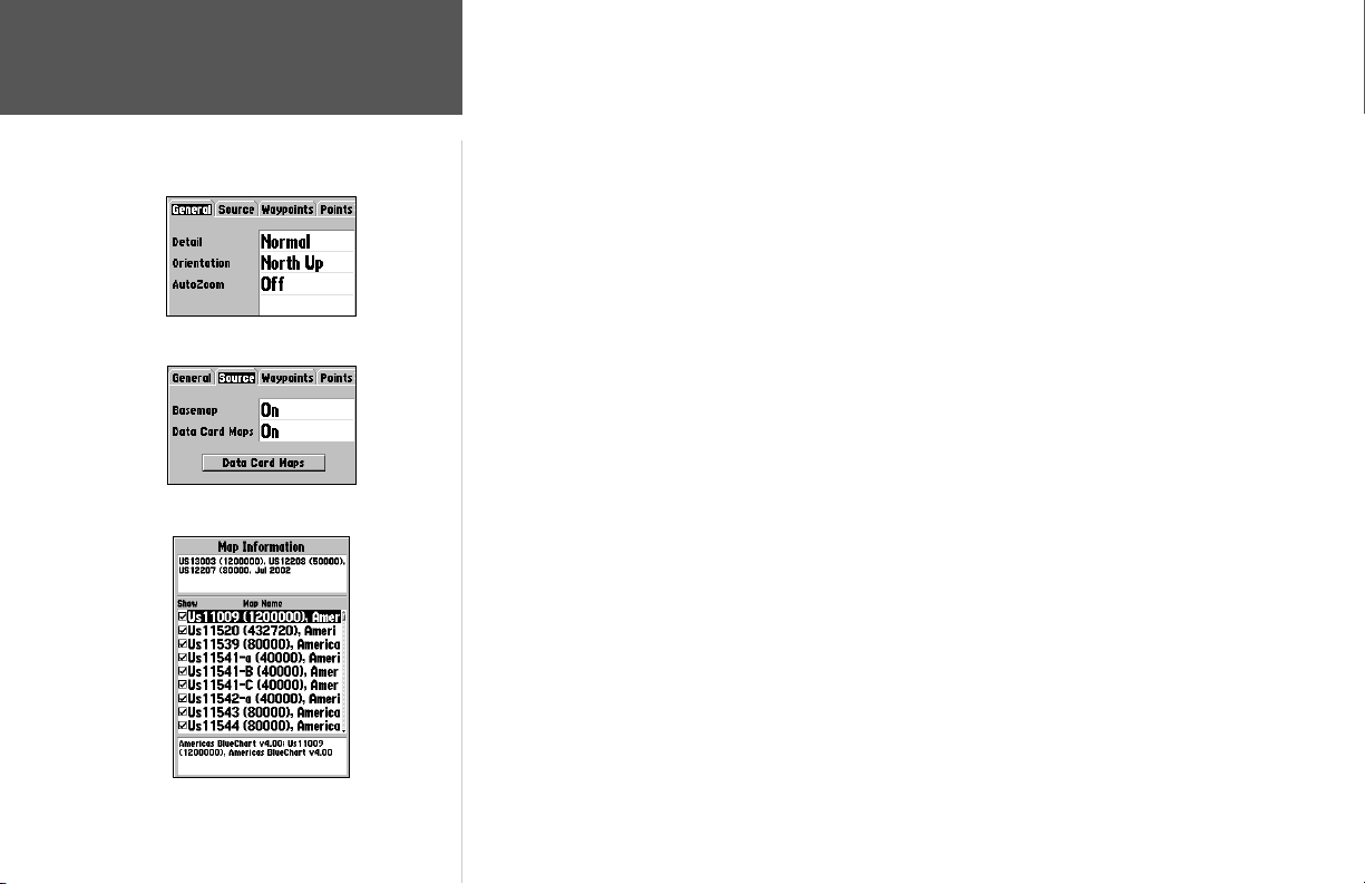
30
Reference
Map Page Options
General Tab
Source Tab
Data Card Information page
General Tab
Detail— Most, More, Normal, Less, Least: controls how much map detail you will see. This setting
only applies to any map feature set to “Auto”. Those features which have a specifi ed scale or turned
“Off” are unaffected by this setting.
Orientation— North Up: fi xes the top of the map display to a north heading; Track Up: fi xes the top
of the map display to the current track heading; Course Up: fi xes the map so the direction of navigation is always “up” and turns the navigation leg line vertical on the screen.
AutoZoom— On/Off: when “On” the map will automatically adjust the map scale to a lower scale as
you approach you destination point.
Source Tab
Basemap— On/Off: turns the built in basemap on or off.
Data Card Maps— On/Off: turns all optional BlueChart/MapSource data loaded on the data card
on or off. The ‘Data Card Maps’ option box shows a list of the optional BlueChart/MapSource data
loaded on the data card. Each area is described by name and may be deselected if you do not wish
to display the data on the Map Page.
To view data card map information:
1. Highlight the ‘Data Card Maps’ option box and press ENTER.
2. Use the ARROW KEYPAD to scroll through the list of maps.
3. To select/deselect a map, highlight the check box to the left of the name of the desired map. Press
ENTER to select/deselect the map. The map is selected and will be displayed on the Map Page
when an “9” appears in the box adjacent to that map. You may also press MENU and choose to
‘Show All’ or ‘Show None’ and press ENTER.
4. To display detailed information and notes for each area, highlight the desired name and press
ENTER. To view the notes for that area, choose ‘Show Notes’. To scroll through the notes, you may
either highlight the notes, press ENTER and press UP/DOWN on the ARROW KEYPAD; or press
MENU, choose the desired scroll option and press ENTER.
5. To exit the notes, highlight ‘Next’ to view the notes for the next map area, or highlight ‘Map List’ to
return to the map list and press ENTER. Press QUIT to exit.
Page 41
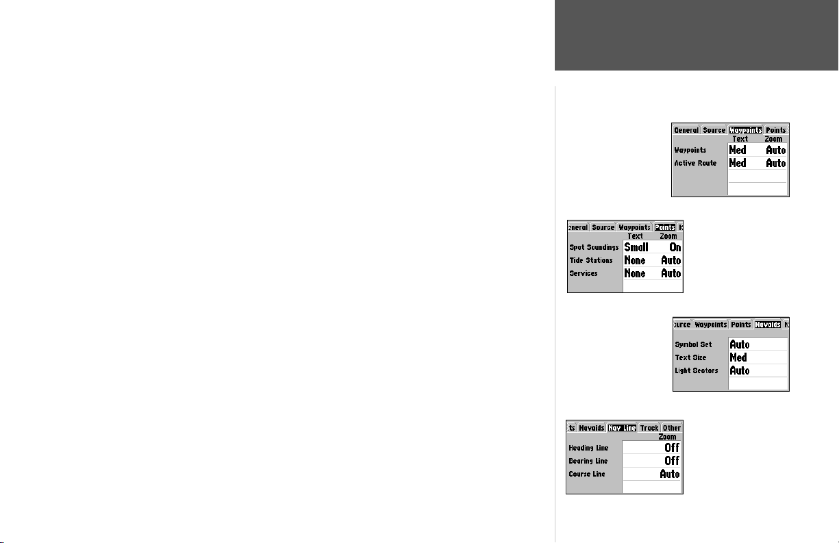
Waypoints Tab— Waypoints/Active Route
Text— None, Small, Medium, and Large: controls the screen size of the name.
Zoom— Auto, Off, 20 ft.–800 ft., 0.2 nm–800 nm: sets the maximum scale at which the feature
appears on the screen. Some types of data will only show up to certain zoom scales.
Points Tab
Text— None (except Spot Sound), Small, Medium, and Large: controls the screen size of the name.
Zoom— Auto, On (Spot Soundings only), Off, 20 ft.–800 ft., 0.2 nm–800 nm: sets the maximum
Navaids Tab
Symbol Set— controls the desired Navaid symbol set. Auto: BlueChart maps are drawn using
Text Size— None, Small, Medium and Large: controls the screen size of the name.
Light Sectors— Controls the drawing of light sectors on the map. When enabled, color units
Nav Line Tab
Heading Line— On/Off: draws an extension from the end of the boat icon in the direction of travel.
Bearing Line— Auto, Off, 20 ft.-800 ft., 0.2 nm-800 nm: sets the scale at which the Bearing Line
Course Line— Auto, Off, 20 ft.-800 ft., 0.2 nm-800 nm: sets the scale at which the Course Line
— Spot Soundings/Tide Stations/Services/Navaids
scale at which the feature appears on the screen. Some types of data will only show up to certain
zoom scales.
symbols similar to the NOAA/NIMA standard; non-BlueChart symbols are drawn using traditional
Garmin symbols. Garmin: All maps are drawn using traditional Garmin symbols. NOAA: All maps
are drawn using a symbol set similar to NOAA/NIMA. International: All maps are drawn using a
symbol set similar to the IALA symbol set.
indicate the actual color of each sector using the color of the light. Monochrome units draw white
and yellow sectors as white, and draw blue, red & green sectors as dark gray. Off: no light sectors
are ever drawn. Auto: Light sectors appear when you point to them with the map cursor. On: Light
sectors are drawn for all lights that have them.
appears on the screen. The Bearing line shows the bearing from your current location to a destination waypoint.
appears on the screen. The Course Line shows a direct navigation line from the point navigation was
initiated to a destination waypoint.
Reference
Map Page Options
Waypoints Tab
Points Tab
Navaids Tab
Nav LineTab
31
Page 42
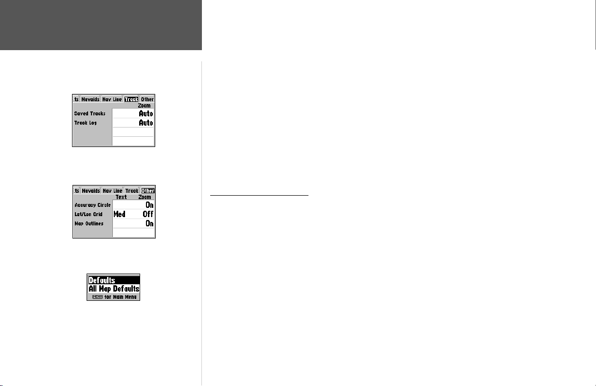
Reference
Map Page Options
Track Tab
Other Tab
Map Setup Menu Options
Track Tab— Saved Tracks/Track Log
Zoom— Auto, Off, 20 ft.–800 ft, 0.2 nm–800 nm.: sets the maximum scale at which the feature
appears on the screen. Some types of data will only show up to certain zoom scales.
Other Tab
Accuracy Circle— On/Off: toggles the circle “On” and “Off”. The circle represents the approximate
accuracy of the unit based on EPE, DOP, and basemap quality. You position will be within the circle.
Lat/Lon Grid— Text: None, Small, Medium, and Large; controls the screen size of the name.
Zoom— Auto, Off, 20 ft.–800 ft, 0.2 nm–800 nm.: sets the maximum scale at which the feature
appears on the screen.
Map Outlines— On/Off: toggles the coverage boxes for BlueChart/MapSource data “On” and “Off”.
• Turn Declutter On/Off — toggles between showing spot soundings and map outlines for easier
viewing.
Map Setup Menu Options
From the map setup page, you can access the following menu options:
• Defaults— restores settings back to factory settings for the tab highlighted.
• All Map Defaults— restores settings back to factory settings for all tabs.
To restore defaults for map settings:
1. From the Map tab in the Main Menu, highlight the tab you want to restore settings to and press
MENU.
2. Highlight ‘Defaults’ (highlight ‘All Map Defaults’ if you want all tabs restored) and press ENTER.
32
Page 43
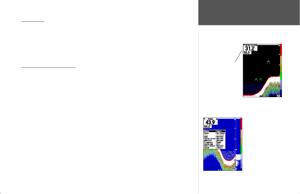
Sonar Page
The Sonar Page is where your GPSMAP 188/188C/238 Sounder becomes a powerful fi shfi nder/
fl asher. Fish are displayed as colored arches or as fi sh icons in three different sizes. Thermoclines are
shown as shades of blue. The area of strongest sonar return (or whiteline) is displayed as solid white.
Typically, the bottom will be the primary whiteline. A thin whiteline indicates a soft bottom while a
thick whiteline will follow the contour of the bottom and show any objects of reasonable size. For more
information on understanding sonar and the display, see page 14 and Appendix I.
Using the Adjustment Menu
The Adjustment Menu allows direct access to the settings and features most commonly used on the
Sonar Page. The currently selected option appears in the upper left of the display.
To select an adjustment option from the Sonar Page:
1. Press the ARROW KEYPAD LEFT/RIGHT to scroll through the options in the upper left of the
display, then press ENTER to access the desired option’s adjustment window.
OR:
1. Press MENU, highlight ‘Adjustments’ and press ENTER. A list of all options and their current settings appears, with the selected option highlighted. Press UP/DOWN on the ARROW KEYPAD to
select the desired option and press ENTER to access the adjustment window.
To easily exit any of the adjustment options, press the QUIT key.
To change an Adjustment Menu setting:
1. Select an adjustment option to change using one of the two methods described above. The adjustment window will automatically timeout and disappear when idle for 20 seconds.
2. Press the ARROW KEYPAD UP/DOWN to place the pointer or setting bar at the desired setting,
range or percentage (Off, 1-100%).
3. Press ENTER or QUIT to exit the adjustment window; or press LEFT/RIGHT on the ARROW
KEYPAD to view another adjustment window.
Reference
Sonar Page
Adjustment
Menu
Sonar Page
Press MENU and
highlight ‘Adjustments’
to see a list of all options
and their current settings.
33
Page 44
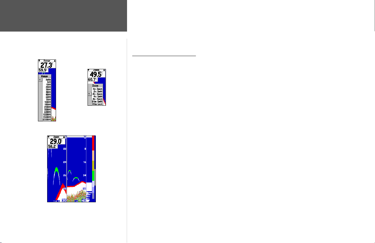
Reference
Sonar Page:
Adjustment Menu
Zoom Adjustment
Range Adjustment
4X Split Zoom Display (Dual Frequency Mode)
34
To change a setting back to ‘Normal’ or ‘Auto’:
1. On the adjustment window for the desired option, press MENU.
2. Select the desired setting and press ENTER.
Adjustment Menu Options
Range— sets the display depth range used for viewing. The unit can be set to automatically track
the bottom or set to a user-specifi ed depth range. Auto mode displays the most information possible while continuously showing the bottom.
Zoom— used to quickly select a display zoom scale or split the display. When a scale other than
‘No Zoom’ is selected, the Adjustment Menu displays a new selection labeled ‘View.’ The Zoom
setting is divided into six display levels:
• 2X Split: shows two reduced-size sonar pictures at the same time. The right half of the display
screen shows the complete sonar picture at its original scale. The left half shows a portion of the
original picture at 1/2 depth scale.
• 2X Zoom: displays the 2X zoomed picture on the full screen and does not show the original
depth scale.
• 4X Split: shows two reduced pictures; the right at the original depth scale and the left at 1/4 the
original depth scale.
• 4X Zoom: displays only the 4X zoomed picture on the full screen. However, if ‘Dual Frequency
Display’ is set to ‘Split’, then a 50/200kHz split screen will be displayed.
• Btm (Bottom) Split: shows two reduced pictures; the right at the original depth scale and the
left showing sonar returns from the bottom up. All target depths will read as a distance form the
bottom.
• Btm (Bottom) Lock: displays only the Bottom Lock picture (returns from the bottom up) on the
full screen. However, if ‘Dual Frequency Display’ is set to ‘Split’, then a 50/200kHz split screen
will be displayed.
Page 45
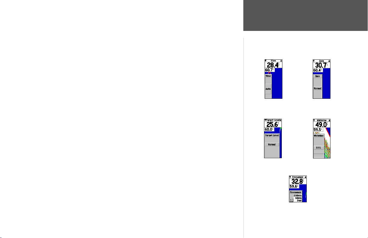
Once activated, the zoomed picture becomes the Sonar Page display. You may also cycle through
the sonar zoom display levels by pressing the IN or OUT keys. The Zoom function can be deactivated
by pressing the OUT key until the ‘No Zoom’ setting appears.
View/Span— available when a Zoom scale other than ‘No Zoom’ is selected. The ‘View’ or ‘Span’
setting is used to change the viewing range of a zoomed display. If the Zoom is set to 2X split or 4X
split, only the zoomed portion on the left side of the screen is affected by the change. If the Zoom
is set to Bottom Split or Bottom Lock, ‘Span’ adjusts how far off the bottom the unit displays data.
In Zoom mode, you can control the view of the left side of the split.
Gain— allows you to control the sensitivity of the unit’s receiver. This provides some fl exibility in
what is seen on the display. To see more detail, increase the receiver sensitivity by selecting a higher
gain percentage. If there is too much detail or if the screen is cluttered, lowering the sensitivity may
increase the clarity of the display.
Target Level— adjusts how dark/light a return (or target) is displayed on the screen. A Color Bar
(see also page 39) appears on the right side of the screen as you adjust this setting. The higher the
percentage, the darker the return appears. This setting does not increase/decrease the unit Gain.
Whiteline— controls how the unit displays information about the bottom type (hard or soft).
With the Whiteline ‘Off’, the bottom return displayss as red and contains no information on
bottom hardness. With Whiteline set at ‘Normal’ or 1-100%, the bottom return becomes white
with a red line indicating where the water meets the bottom. To turn the Whiteline Off, press the
ARROW KEYPAD DOWN until the setting bar is all the way at the bottom of the range and reads
“Off”. See page 114 for more detail on this feature.
Frequency— allows you to choose a transducer frequency. Frequency refers to the “pitch” of
the sound that the transducer sends and receives. You may choose ‘200kHz’, ‘50kHz’ or ‘Dual’
frequency.
Reference
Sonar Page:
Adjustment Menu
View Adjustment Gain Adjustment
Target Level Adjustment Whiteline Adjustment
Frequency Adjustment
35
Page 46
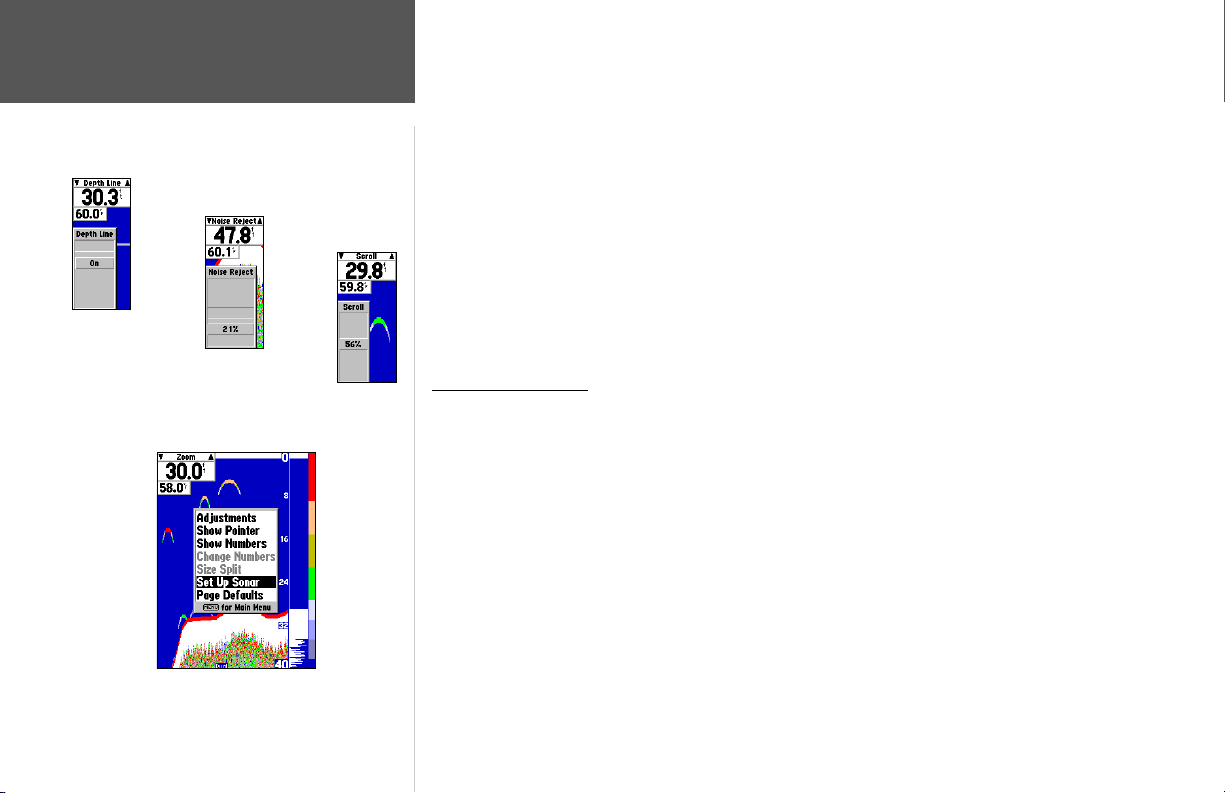
Depth Line
Adjustment
36
Reference
Sonar Page Options
Noise Reject
Adjustment
Sonar Page Menu Options
Scroll
Adjustment
Depth Line— adds a horizontal depth line across the display which is used to measure the depth
of underwater objects. The depth of the line appears in a box on the right side of the line. Press UP
or DOWN on the ARROW KEYPAD to control the position of the line on the graph. The depth is
displayed in a window on the right side of the line. To turn the Depth Line Off, press the ARROW
KEYPAD UP until the setting bar is all the way at the top of the range and reads “Off”.
Noise Reject— helps fi lter unwanted noise from the graph. The ‘Noise Reject’ tool can be turned
‘Off’, set to ‘Normal’ (automatically adjusts for optimum viewing) or to a fi xed 1-100% setting.
When setting the Noise Reject tool: the HIGHER the noise rejection setting, the unit is more likely
to NOT show fi sh or structure. To turn the Noise Reject Off, press the ARROW KEYPAD DOWN
until the setting bar is all the way at the bottom of the range and reads “Off”.
Scroll— adjusts the rate that the graph scrolls from right to left. If you are sitting still or the graph
is moving too fast, slowing the scroll rate or pausing it can be benefi cial.
Sonar Page Options
The GPSMAP 188/188C/238 Sounder’s Sonar Page features a menu page that provides access to
additional functions and to layout and data fi eld options.
To display the Sonar Page options:
1. Press MENU.
To select a menu option:
1. Use the ARROW KEYPAD to highlight the desired option and press ENTER.
The following options are available:
• Adjustments — lists the Adjustment Menu options and their current settings (see page 33-35).
To change an Adjustment setting:
1. On the Adjustment options list, use the ARROW KEYPAD to highlight the desired option and press
ENTER.
2. Use the ARROW KEYPAD to make the desired change and press ENTER.
Page 47
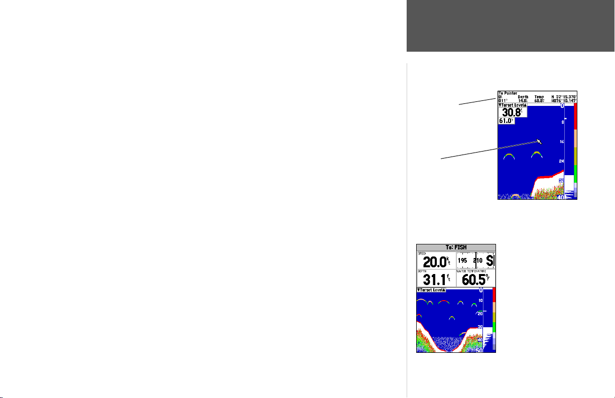
• Show/Hide Pointer — allows you to reference sonar items and mark underwater waypoints. This
makes it easier to fi nd and use an object such as a stump for a future fi shing location. When using
this feature, the Sonar Page pauses. The pointer does not move off the paused display and cannot
show an area that has scrolled off the screen. The depth is updated while the display is paused, but
the unit will not show any new sonar data until the standard Sonar Page is resumed. You may see a
discontinuity from where the sonar information stops to where it starts again.
To mark an underwater waypoint:
1. From the Sonar Page, press MENU, highlight ‘Show Pointer’ and press ENTER to pause the screen
movement.
2. Use the ARROW KEYPAD to move the cursor onto the target (underwater drop off, stump, etc.)
you want to mark. The data window at the top of the screen displays the cursor’s depth, coordinates, and bearing and distance from your current position.
3. Press ENTER/MARK. The New Waypoint page appears with the waypoint’s coordinates, default
three-digit name, and pointer depth automatically fi lled in.
4. To change the name, symbol or depth, highlight the appropriate fi eld and press ENTER. Make your
changes and press ENTER when done.
5. When done, move the fi eld highlight back to the ‘OK’ prompt and press ENTER.
6. To return to the standard Sonar Page, press QUIT; or press MENU, then highlight ‘Hide Pointer’
and press ENTER.
• Show/Hide Numbers — toggles showing/hiding the data fi elds on the sonar display.
• Change Numbers — allows you to specify the type of data displayed in each data fi eld. For detailed
instructions on changing the data fi elds on the Sonar Page, see pages 26-28.
Reference
Sonar Page Options
Data Window
Pointer
‘Show Pointer’ option enabled
‘Show Numbers’
option enabled
37
Page 48
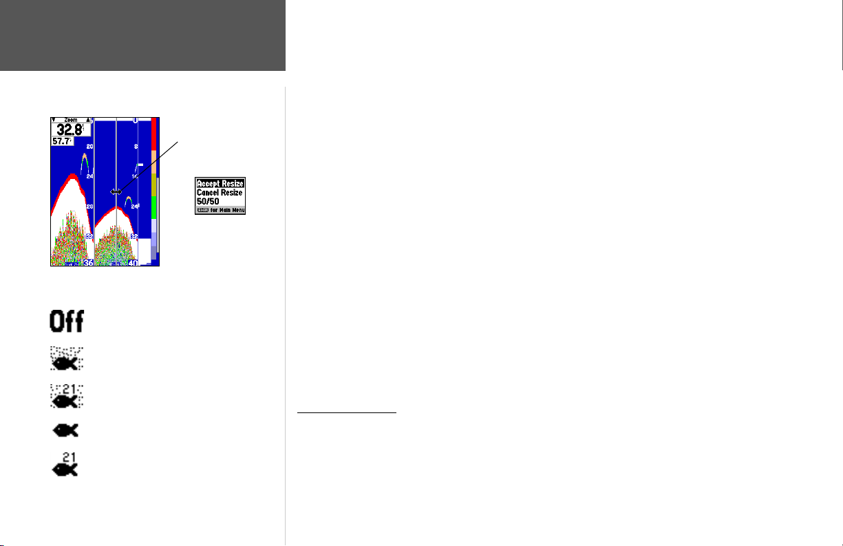
Reference
Sonar Page Options
‘Size Split’ Menu Options
Resizing the Split Sonar Display
Fish Symbols Off— All available information
will be displayed.
Suspended targets displays as fi sh symbols.
Background information will be displayed.
Same as above with the target depth attached.
Suspended targets display as fi sh symbols. No
background information will be displayed.
Same as above with target depth attached.
38
Double-Arrow
• Size Split — enables width adjustment of the Sonar Page split screen. This option is only available
when a split screen zoom scale is selected. You may adjust the size of the split window anywhere
from 1/4 to 3/4 width of the right half of the Sonar Page.
To resize the Sonar Page split screen:
1. From the Sonar Page split screen, press MENU.
2. Using the ARROW KEYPAD, highlight ‘Size Split’ and press ENTER.
3. Move the horizontal double-arrow LEFT or RIGHT using the ARROW KEYPAD until the desired
vertical width line shows, then press ENTER.
4. If you wish to cancel this operation, press QUIT or press MENU, highlight ‘Cancel Resize’ and press
ENTER.
• Set Up Sonar — jumps to the Sonar tab of the Main Menu, which contains sonar confi guration
settings that should not require frequent change. You may also press MENU twice from any screen,
then highlight the ‘Sonar’ tab using the ARROW KEYPAD. Press RIGHT on the ARROW KEYPAD
to access the selection fi elds. Each time the Setup Menu is accessed, the unit will return to the last
edited selection fi eld.
To change a setting on the Sonar tab:
1. Using the ARROW KEYPAD, highlight the desired fi eld and press ENTER and the available options
appears.
2. Highlight the desired setting and press ENTER.
3. Press QUIT to return to the Sonar Page or previous page.
Sonar Tab Options
Fish Symbols — allows you to determine how the graph displays underwater targets and background information. If Fish Symbols are set to ‘Off’, the unit displays all of the available information about the underwater environment. If a fi sh symbol is selected, the graph displays only the
information related to that symbol. Actual fi sh returns may not always appear as perfect arches
(like in simulator mode), due to the speed, fi sh orientation and/or other conditions.
Page 49
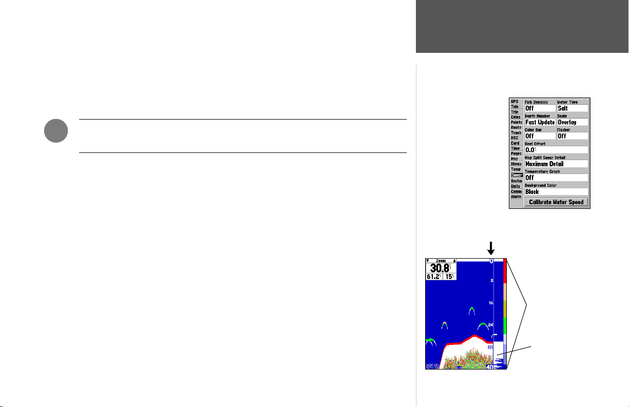
Water Type — since sound waves travel through ‘Fresh’ and ‘Salt’ water at different rates it is
necessary to select the ‘Water Type’ to ensure accurate readings on the unit.
Depth Number — controls the effi ciency of the digital depth update rate.’Fast Update’ will update
more quickly and is recommended for low-noise, deeper water (>50 ft.). ‘Auto’ is best for shallow
water or high noise areas, will have a slower screen update and is best used if you travel a wide
variety of depths.
Reference
Sonar Tab Options
,
If the unit is unable to track the bottom for any reason, the digits in the depth window
will fl ash on and off to alert you that the unit is not tracking the bottom.
Scale — controls the depth ‘Scale’ displayed vertically along the right side of the graph. The depth
‘Scale’ can be confi gured to display four different ways: as an ‘Overlay’, in the ‘Corners’, with ‘Basic’
or ‘No Scale’.
Color Bar — shows a gradient scale of the current Target Level setting (see page 35).
Flasher — with the ‘Flasher’ active, a graphic Flasher representation will be displayed on the far
right side of the graph. This graphic Flasher displays structure and bottom returns much the same
as a true Flasher. You may fi nd this feature particularly useful when using ‘Fish Symbols’.
Keel Offset — used to offset the surface reading for the depth of a keel. This makes it possible to
measure depth from the bottom of your keel instead of from the transducer’s location. Enter a positive number to offset for a keel, or enter a negative number to compensate for a large vessel that
may draw several feet of water. The ‘Keel Offset’ will be refl ected in the depth reading.
Map Split Sonar Detail — controls Map Page sonar split range scale. ‘Full Range’ will show
entire scale of 2X or 4X left side split of Sonar Page. ‘Maximum Detail’ displays what is shown on
the left side of a split sonar screen.
Background Color — (GPSMAP 188C only) sets the background color on the Sonar Page to
Black, Blue or White.
Main Menu—Sonar Tab
(GPSMAP 188C shown)
Depth Scale (Overlay)
Color Bar
Flasher
39
Page 50
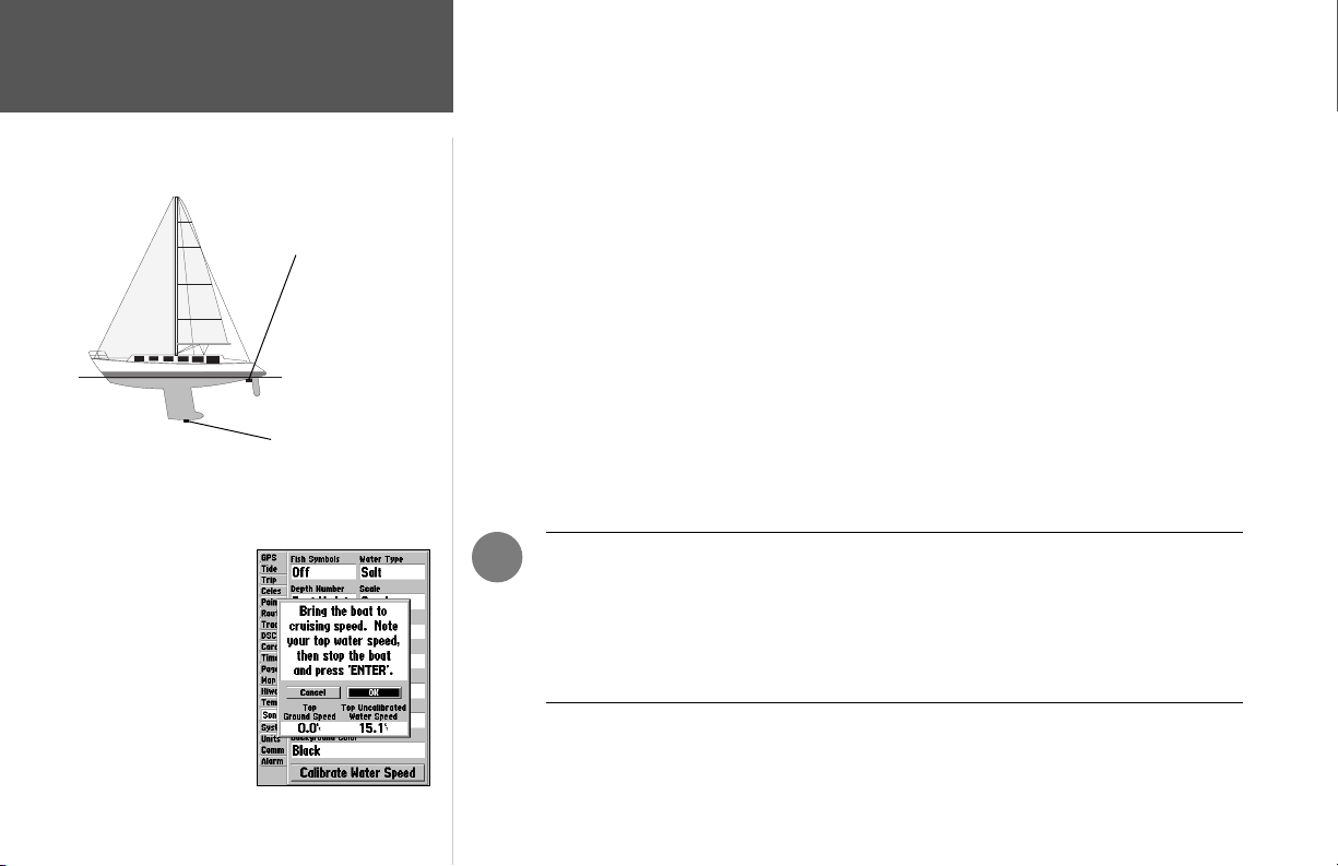
Reference
Sonar Page Options
Transducer at Surface
Enter (+) positive
number to show depth
from bottom of keel
Keel Offset: Transducer
at Bottom of Keel
Enter (-) negative number to
show depth from surface
Keel Offset:
Calibrate Water Speed — this is only available if you are using a speed-capable transducer/sensor.
Calibration is required to ensure that the Water Speed displayed on your unit will be accurate. The
unit will automatically use the GPS ground speed, if it is available, for comparison on the calibration. If a GPS ground speed is not available, use either your boat’s speedometer reading (not always
accurate) or a stopwatch to determine your speed over a certain distance (distance / time = speed).
It is recommended that the calibration take place in water having little or no current.
To calibrate the water speed:
1. On the Sonar tab, use the ARROW KEYPAD to highlight ‘Calibrate Water Speed’ and press
ENTER.
2. Bring the boat to a cruising speed. The top ground and uncalibrated water speeds will be shown
at the bottom of the calibration window. Note your top water speed, then stop the boat and press
ENTER.
3. By default, the top ground speed is automatically shown in the ‘What was your top water speed?’
fi eld. If a ground speed is not available, the top uncalibrated water speed is used instead. If the new
speed is correct, highlight ‘OK’ and press ENTER. If you wish to manually enter a calibration, press
ENTER on the speed fi eld, enter a new speed and press ENTER.
4. You may also press MENU from the calibration screen and choose ‘Use Top Ground Speed’ to
default back to ground speed or ‘Use No Calibration’ to use the speed sensor’s uncalibrated speed.
40
Calibrating the
Speed Sensor
,
NOTE: If the boat is not moving fast enough or the speed sensor is not outputting a
speed, you will see a “Boat Is Not Moving Fast Enough To Calibrate” message at the
bottom of the display. Check that the speed sensor wheel is moving or safely increase
boat speed. If there is a problem with the speed sensor/unit or if a speed senor is not
installed, a “Water Speed Sensor Is Not Working” message appears at the bottom of
the display. Check connections of speed sensor cables.
• Page Defaults — restores the Sonar Page settings to the original factory setup.
To restore default settings to the Sonar Tab:
1. Press MENU. With ‘Page Defaults’ highlighted, press ENTER.
Page 51
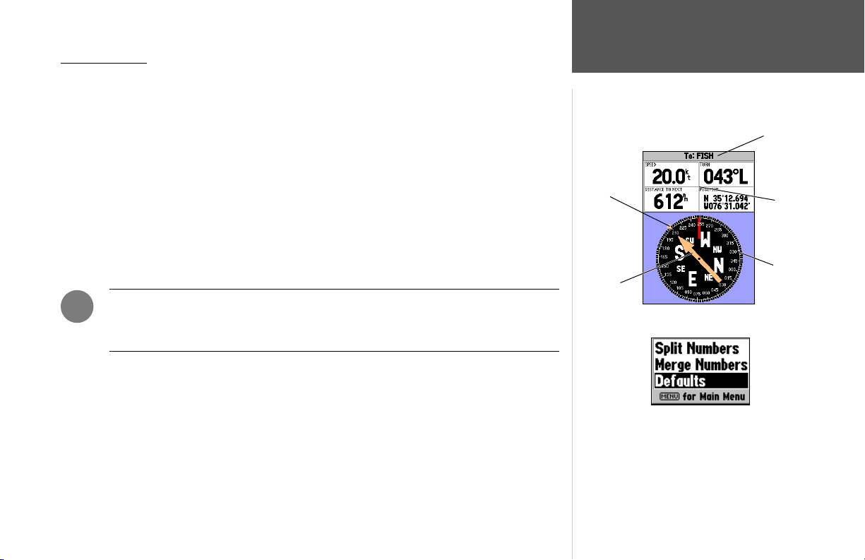
Compass Page
The GPSMAP 188/188C/238 Sounder features two different navigation pages: Compass and Highway. Whenever a NAV, Follow Track (TracBack), or Follow Route have been activated, the GPSMAP
188/188C/238 Sounder’s Compass Page will guide you to your destination with digital readouts and
a graphic compass display, which includes a bearing pointer. Use this page (instead of the Highway
Page) when travelling at slower speeds, when making frequent directional changes, or where straightline navigation is not possible due to obstructions or terrain. The middle of the page features a rotating
‘compass ring’ that shows your course over ground (track) while you’re moving. Your present course
over ground is indicated at the top of the compass ring. A bearing pointer arrow, in the middle of the
Bearing
‘Bug’
compass ring, and a bearing ‘bug’ indicator on the outside of the compass ring, indicate the direction of
the destination (bearing) relative to the course over ground. The compass ring and pointer arrow work
independently to show—at a glance—the direction of your movement and the direction to your destination. For instance, if the arrow points up, you are going directly to the waypoint. If the arrow points
any direction other than up, turn toward the arrow until it points up, then continue in that direction.
,
The bearing pointer, bearing bug and/or compass ring may point in various directions
when you are stationary or at very low speeds. Once you start moving, the pointer will
be correct.
Bearing
Pointer
The Compass Page features a menu page that provides access to layout and data fi eld options. The
data window, located at the top of the page, provides a user-selectable layout of various types of useful
data. Each data fi eld may be confi gured to display several data options. The data window layout may
also be changed to display more/less data fi elds and change the actual size of the data displayed.
To change the data fi elds or layout of the Compass Page:
1. Press MENU. With ‘Change Numbers’ highlighted, press ENTER.
2. Highlight the data fi eld you want to change. Press ENTER to select from a list of data to be displayed; or press MENU to split or merge the numbers. Make your selection and press ENTER.
For detailed instructions on changing the data fi elds and layout of the Compass Page, see pages 26-28.
1. Press MENU, then press ENTER.
2. Press MENU again, highlight ‘Defaults’ and press
Reference
Compass Page
Destination
Data Fields
Compass
Ring
To restore defaults to the Compass Page:
ENTER.
41
Page 52
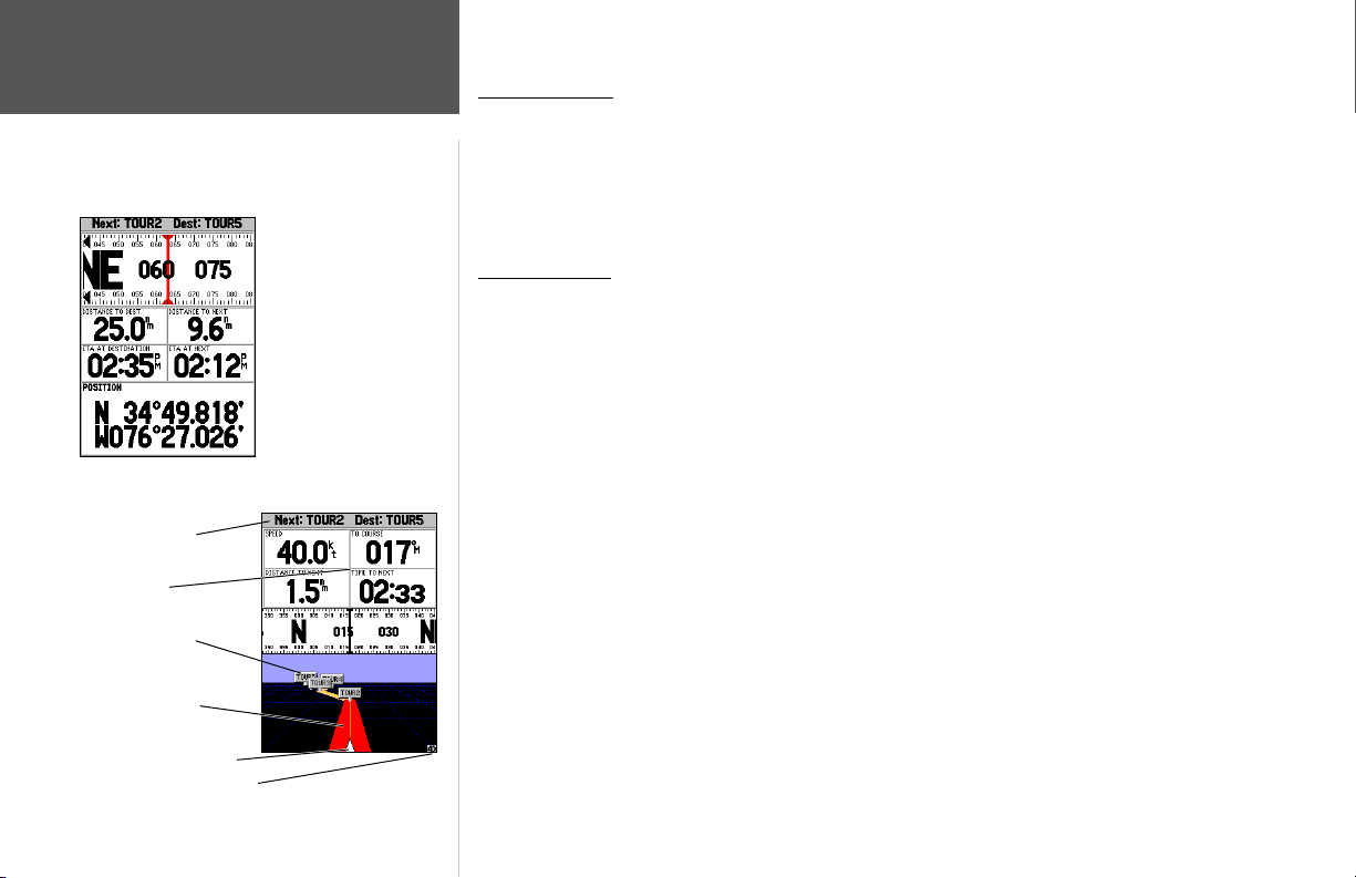
Numbers Page/
Highway Page
Current Nav Point
Data Fields
Route Waypoints
Desired Track Line
Current Position
42
Zoom Scale
Reference
Numbers Page with the
middle data fi eld split into
four small data fi elds.
Numbers Page
The Numbers Page provides a quick reference for the important data you want to display. The
default page displays three large, user-selectable data fi elds showing a compass ribbon, speed and current position coordinates. You may also choose to show the three data fi elds in large lettering for better
readability or you may ‘split’ any or all of the data fi elds to show 4 smaller data fi elds. For detailed
instructions on changing the data fi elds and layout of the Numbers page, see pages 26-28.
Highway Page
When a Go To, TracBack, or route has been activated, the GPSMAP 188/188C/238 Sounder’s
Highway Page provides digital and graphic steering guidance to the destination. The top half of the
Highway Page features user-selectable data fi elds that display useful navigation data. Additionally, a
compass ribbon is displayed to show your current heading along with a dark, vertical bar indicates the
bearing to your course. To stay on course, steer towards the black vertical indicator (or arrows) until it
lines up with the red bar in the middle. The bottom section of the screen provides visual guidance to
the waypoint on a graphic highway display. The line down the center of the highway represents your
desired track line.
As you head toward your destination, the highway perspective moves to indicate your progress to
the waypoint and which direction you should steer to stay on course. If you are navigating a route, the
Highway Page shows each route waypoint in sequence connected by a red “road” with a yellow line
down the middle, which is your desired track line. Nearby waypoints not in the active route can also
be displayed. The highway perspective scale may also be zoomed in or out to display a larger or smaller
view of the highway. Five settings are available from 1X to 16X, with a default setting of 8X.
To change the highway perspective scale:
1. Press the ZOOM IN or ZOOM OUT key to select the desired setting.
Highway Page
Page 53
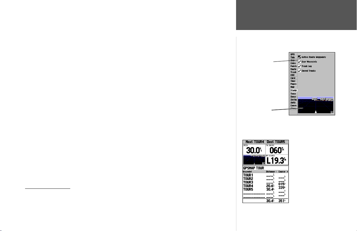
The Highway Page options menu provides access to functions and features relating to the Highway
Page and the layout options. The data window, located at the top of the page, provides a user-selectable
layout of various types of useful data. Each data fi eld may be confi gured to display several data options.
The data window layout may also be changed to display additional data fi elds and change the actual
size of the data displayed.
To display the Highway Page options:
1. Press MENU.
To select a menu option:
1. Using the ARROW KEYPAD, highlight the desired option and press ENTER.
The following options are available from the Highway Page menu:
• Change Numbers — allows you to specify the type of data displayed in each data fi eld on the High-
way display. For detailed instructions on changing the data fi elds and layout of the Highway page, see
pages 26-28.
• Set Up Highway — jumps to the Hiway tab of the Main Menu, allowing you to select which
waypoints and tracks are shown on the Highway display. Use the
ARROW KEYPAD
and
ENTER
key
to select/deselect the desired options. Four options are available:
• Active Route Waypoints— all active route waypoints.
• User Waypoints— only nearby waypoints to the route.
• Track Log— current active track log.
• Saved Tracks— any saved track logs near the route.
Active Route Page
When a route is activated in the GPSMAP 188/188C/238 Sounder system, the Active Route page
will show each waypoint of the active route, along with various, user-selectable types of data. For
additional details on the Active Route Page, see page 64.
Reference
Highway Page Options
Check or uncheck
the options you wish
to show/hide on the
Highway Page.
Preview Window
Active Route Page
Selecting the ‘Setup Highway’
option takes you to the Hiway
tab of the Main Menu.
43
Page 54
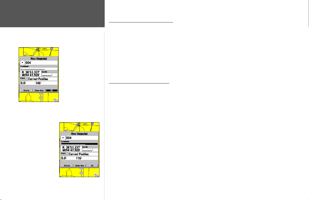
Reference
Creating Waypoints
Highlight a fi eld and press
ENTER to enter a new
symbol, name, comment
or depth.
44
Highlight ‘OK’ and press
ENTER to use the default
name and symbol.
Creating and Using Waypoints
The Garmin GPSMAP 188/188C/238 Sounder stores up to 3000 alphanumeric waypoints with a
user-defi ned icon, comments and depth available for each waypoint. Waypoints can be created using
three basic methods:
• ENTER/MARK key– used primarily for marking your present position, the ENTER/MARK key also
provides options that allow you to select a map position or map item from the map display.
• Graphically– allows you to defi ne a new waypoint position from the map display using the ARROW
KEYPAD. (For creating underwater waypoints, see page 37.)
• Text Entry– allows you to enter a new waypoint’s coordinates manually (from a chart, etc.).
Marking Your Present Position
The Garmin GPSMAP 188/188C/238 Sounder’s ENTER/MARK key lets you quickly capture your
present position (or cursor or map item position) in order to create a new waypoint. You must have a
valid position (2D or 3D) fi x to mark your present position. This can be determined by looking at the
GPS tab on the Main Menu.
To mark your present position:
1. Press and hold the ENTER/MARK key until the ‘New Waypoint’ window appears, then release it.
You will see a default three-digit name and symbol for the new waypoint.
2. To accept the waypoint with the default name and symbol, press ENTER to confi rm the highlighted
‘OK’ prompt.
3. To enter a different name, highlight the name fi eld and press ENTER, then use the ARROW
KEYPAD to enter the new letters/numbers and press ENTER when done. You may use up to 10
alphanumeric characters for the name.
4. To enter a different symbol, highlight the symbol fi eld to the left of the name and press ENTER,
then use the ARROW KEYPAD to highlight the new symbol and press ENTER.
5. To enter optional comments or a depth, highlight the appropriate fi eld and press ENTER, then use
the ARROW KEYPAD to enter a value and press ENTER.
Page 55
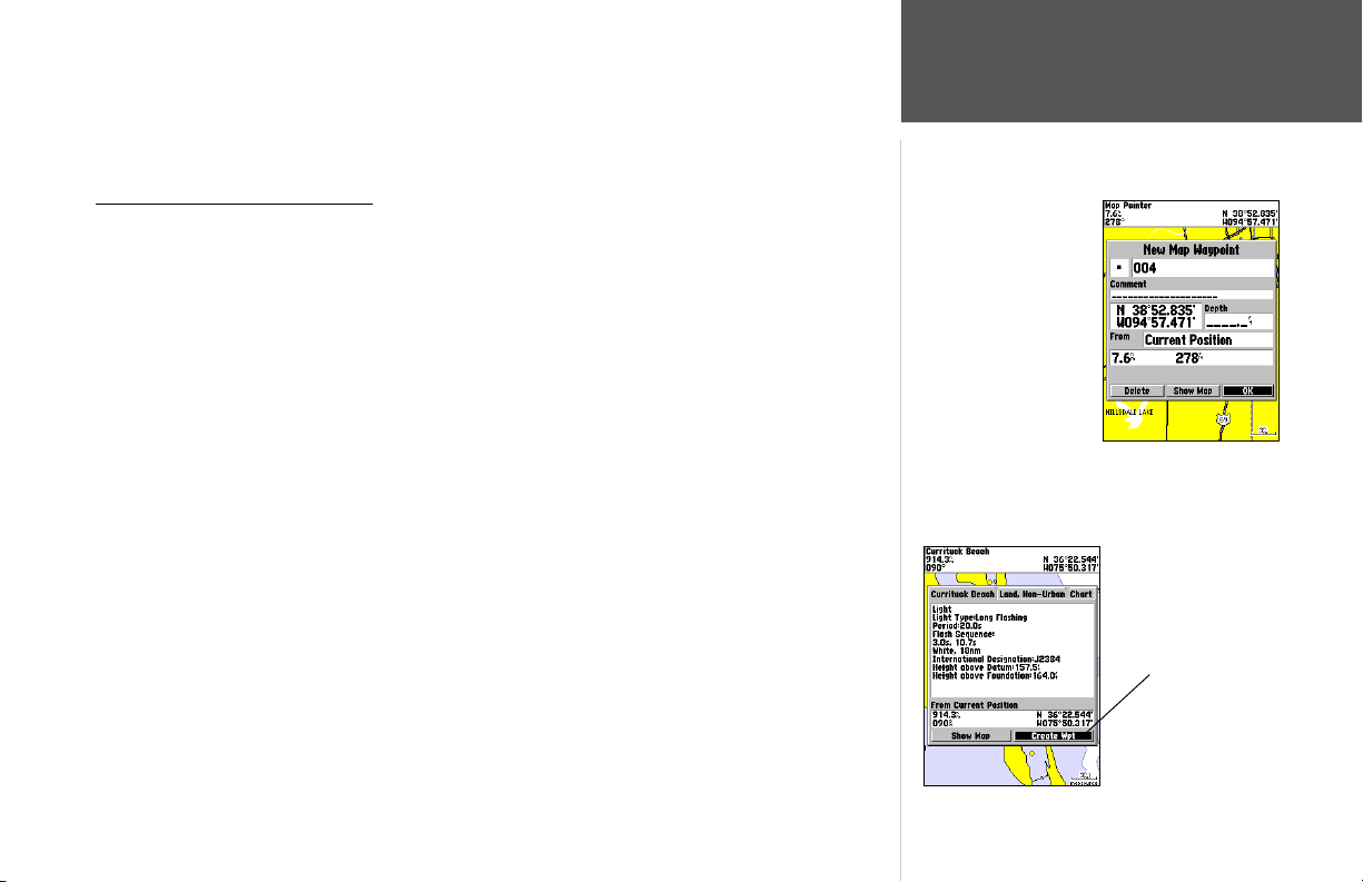
6. To manually enter a set of coordinates, highlight the coordinates and press ENTER, then use the
ARROW KEYPAD to enter the new coordinates and press ENTER when done.
7. When done, use the ARROW KEYPAD to highlight the ‘OK’ prompt and press ENTER to save the
waypoint into memory.
Creating Waypoints
Creating Waypoints Graphically
Waypoints may also be quickly created with the Map Page cursor, which allows you to ‘point
and shoot’ at any map position or map feature to create a new waypoint. When you move the cursor
over a map item, you will see a highlighted description of that item. The GPSMAP 188/188C/238
Sounder uses the map item text shown on the cartography as the default name and symbol for the new
waypoint.
To create a new waypoint on an open map location:
1. Use the ARROW KEYPAD to move the cursor to the desired map position.
2. Press and quickly release the ENTER/MARK key to capture the cursor position (press and hold
ENTER/MARK to mark your present location, not the map cursor’s position).
3. The ‘New Map Waypoint’ page appears. To accept the waypoint with the default name and symbol,
press ENTER.
To change the name, symbol, position, or add a comment or depth, highlight the appropriate fi eld
and press ENTER. Make your changes and press ENTER when done. After entering and confi rming
your changes, highlight ‘OK’ and press ENTER.
Creating a waypoint on
an open map location.
To create a new waypoint from a map feature:
1. Use the ARROW KEYPAD to move the cursor and highlight the desired map feature.
2. Press ENTER/MARK to capture the cursor position. An Information page for that map feature
appears. Use the ARROW KEYPAD to highlight ‘Create Wpt’ and press ENTER.
3. The ‘New Waypoint’ page appears. To accept the waypoint with the default name and symbol
(based on the map feature), highlight ‘OK’ and press ENTER.
To change the name, symbol, position, or enter comments or depth, highlight the appropriate
fi eld and press ENTER. Make your changes and press ENTER. After entering and confi rming your
changes, use the ARROW KEYPAD to highlight ‘OK’ and press ENTER.
Reference
Using a map item to create
a new waypoint.
45
Page 56
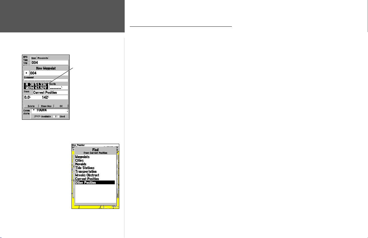
Reference
Creating Waypoints
Select a point from which
to project a new waypoint.
Highlight the position
fi eld and use the
ARROW KEYPAD
to enter the desired
position coordinates.
Additional Options For Creating Waypoints
Waypoints may also be created by manually entering position coordinates through the Points tab
of the Main Menu. This method can be useful for creating a waypoint at a specifi c latitude/longitude
position from a chart.
To create a new waypoint by entering location coordinates:
1. Press MENU twice to display the Main Menu. Highlight the ‘Points’ tab and press MENU.
2. Highlight ‘Create Waypoint’ and press ENTER. The ‘New Waypoint’ page appears, with the next
available waypoint number and the receiver’s last know position as the default name and position.
3. Use the ARROW KEYPAD to highlight the position fi eld and press ENTER. Use the ARROW
KEYPAD to enter the desired position coordinates and press ENTER when fi nished.
4. To change the name, symbol, or enter comments, depth or elevation, highlight the appropriate fi eld
and press ENTER. Make your changes and press ENTER when fi nished.
5. Use the ARROW KEYPAD to highlight ‘OK’ and press ENTER to save the waypoint.
A waypoint may also be created by “projecting” the distance and bearing from a specifi c location to
a new location. Start by accessing the ‘New Waypoint’ page or the ‘New Map Waypoint’ page.
To create a new waypoint by projecting its location:
1. To project the waypoint from your current location, be sure the fi eld to the right of the word ‘From’
reads ‘Current Position’ (if not, highlight the fi eld and press ENTER, highlight ‘Current Position’ and
press ENTER).
2. To select a map location from which to project a waypoint, highlight the fi eld next to ‘From’ and
press ENTER. The ‘Find’ screen appears. Highlight ‘Other Position’ and press ENTER. Use the zoom
IN key and ARROW KEYPAD to highlight the desired position on the map and press ENTER.
46
Page 57
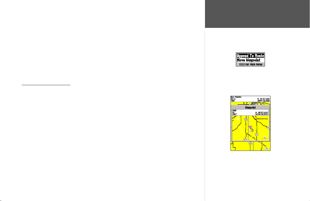
3. To select another location from which to project a waypoint, highlight the fi eld next to ‘From’ and
press ENTER. The ‘Find’ screen appears. Highlight the desired type of location (waypoints, cities,
etc.) and press ENTER. Use the submenus to narrow down your search (for more information see
‘Find’ on pages 38-39). Highlight the desired location and press ENTER. With ‘OK’ highlighted,
press ENTER again.
4. Highlight the distance and/or bearing fi elds below ‘From Current Position’ and press ENTER. Use
the ARROW KEYPAD to enter the projected distance and/or bearing from your current position for
the new waypoint and press ENTER.
5. Make any other desired changes to the new waypoint data (name, symbol, etc.), then highlight ‘OK’
and press ENTER to save the waypoint.
Waypoint Menu Options
Two additional options are available by pressing MENU on the New Waypoint and New Map
Waypoint Pages: Append To Route and Move Waypoint. (these menu options also appear on the
Waypoint Edit and Waypoint Review pages).
• Append to Route— Adds the new waypoint to the end of a route.
• Move Waypoint— Allows you to move the waypoint to a new location on the map display.
To append a new waypoint to a route:
1. Select ‘Append To Route’ from the options menu.
2. The ‘Select Route’ screen appears. Highlight the desired route or select ‘New Route’ and press
ENTER.
3. With ‘OK’ highlighted, press ENTER to save the waypoint.
To move a waypoint:
1. Select ‘Move Waypoint’ from the options menu.
2. The selected waypoint will be centered and highlighted on a map display. Use the ARROW
KEYPAD to move the waypoint to the new position and press ENTER. Press QUIT to exit.
Reference
Creating Waypoints
Waypoint Options Menu
Use the ARROW KEYPAD to move the waypoint to a new
position on the map.
47
Page 58
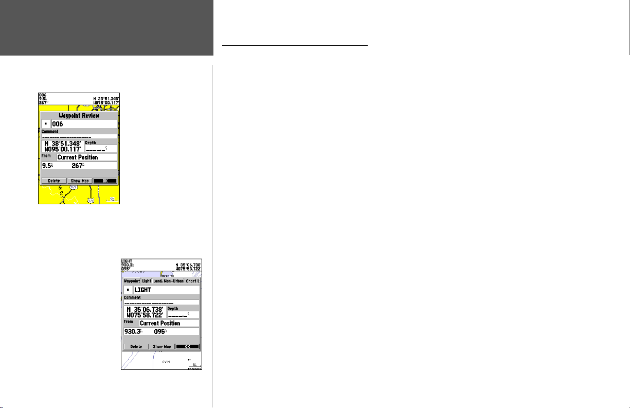
Reference
Reviewing/Editing Waypoints
Waypoint Review Page—
Highlight ‘OK’ and press
ENTER to exit/save
changes and return to the
Map Page.
Waypoint Review Page
for a waypoint located on
multiple map features.
Reviewing and Editing Waypoints
Once you have created and stored a waypoint, it may be modifi ed, reviewed, renamed, moved, or
deleted at any time through the Waypoint Review and Waypoint Edit pages.
To access the Waypoint Review page:
1. Use the ARROW KEYPAD to highlight the desired waypoint on the Map Page.
2. Press ENTER to display the Waypoint Review page. If the waypoint is located on a map feature, or
on a MapSource or BlueChart feature, the Waypoint Review page includes additional information
tabs about the other features at that location.
To access the Waypoint Edit page:
1. Press MENU twice to view the Main Menu. Use the ARROW KEYPAD to highlight the ‘Points’ tab,
then highlight the desired waypoint from the ‘User’ or ‘Proximity’ lists.
2. Press ENTER to display the Waypoint Edit page. If the waypoint is located on a map feature, or on
a MapSource or BlueChart feature, the Waypoint Edit page will NOT display the details of the other
map features.
From the Waypoint Review and Edit pages, you may change the name, symbol, comment, position
coordinates, or depth for the selected waypoint. Once the changes have been made, highlight ‘OK’
(Waypoint Review Page) or ‘Next’ (Waypoint Edit Page) and press ENTER to save them.
To change the waypoint name:
1. Highlight the waypoint name fi eld and press ENTER.
2. Use the ARROW KEYPAD to enter a new name and press ENTER when done.
To change the waypoint symbol:
1. Highlight the waypoint symbol fi eld to the left of the waypoint name and press ENTER.
2. Use the ARROW KEYPAD to select the desired symbol and press ENTER when done.
48
Page 59
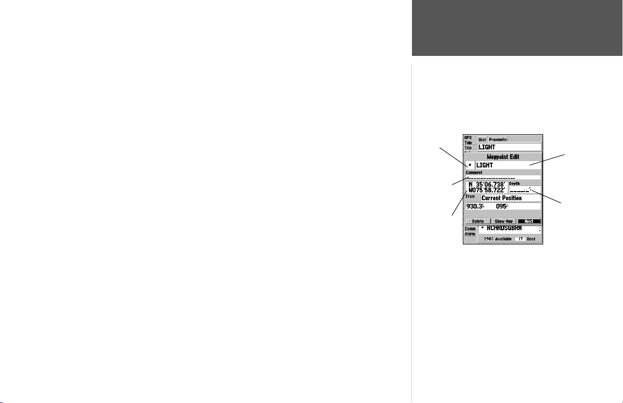
To change the comment/position coordinates/depth:
1. Highlight the desired fi eld and press ENTER.
2. Use the ARROW KEYPAD to edit/enter the data. To drop to the next line, press to the right on the
ARROW KEYPAD. Press ENTER when done.
On the Waypoint Review and Waypoint Edit pages, you may also delete the selected waypoint,
view the waypoint on the map, and move the waypoint on the map.
To delete a waypoint:
1. On the Waypoint Review/Waypoint Edit page, use the ARROW KEYPAD to highlight ‘Delete’ and
press ENTER. With ‘OK’ highlighted, press ENTER again to confi rm the deletion.
To view and move a waypoint on the map:
1. From the Waypoint Review/Waypoint Edit page, highlight ‘Show Map’ and press ENTER. The
waypoint is highlighted on a map screen with an information window that shows the waypoint
name, position and distance and bearing from your current position.
2. To move the waypoint, press ENTER. A ‘MOVE’ label will now appears under the cursor arrow. It
may be necessary to use the IN and OUT keys to zoom the map.
3. Use the ARROW KEYPAD to move the waypoint to a new position. As you move the cursor around
the map display, the information window at the top changes to show the distance, bearing, and
position of the map cursor (in relation to the waypoint’s original position), and a description of
there the cursor is on the map. If you wish to stop the move process, press QUIT.
4. With the pointer at the desired position, press ENTER. To return to the Waypoint Edit/Waypoint
Review page, press QUIT.
On the ‘Show Map’ map display, an additional option is available by pressing MENU:
• Point to on Map Page— returns to the highlighted waypoint on the Map Page (exits the Waypoint
Review/Waypoint Edit Page).
Reference
Editing Waypoints
Symbol
Name
Comment
Depth
Coordinates
Waypoint Edit Page
49
Page 60
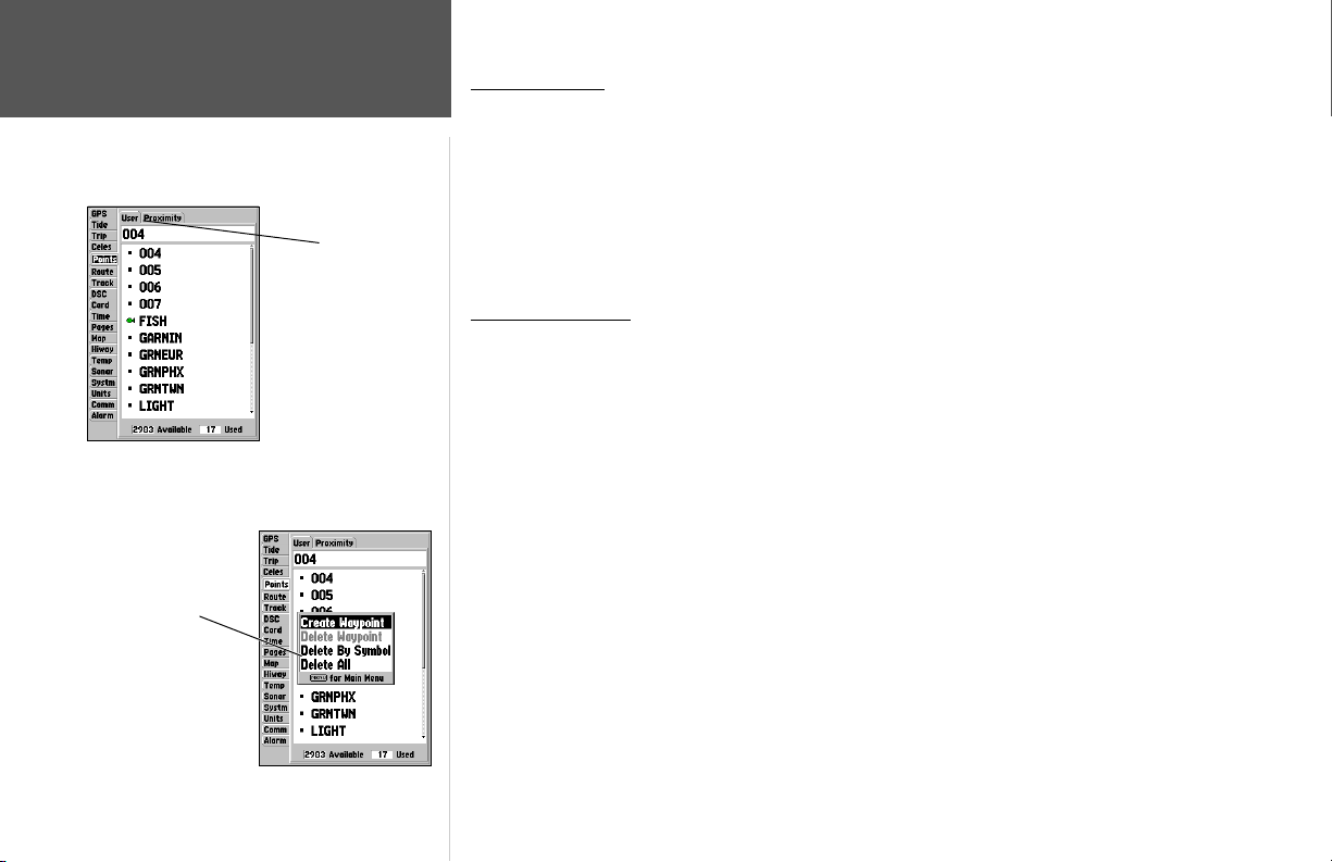
Waypoint Lists
Main Menu—Points Tab
Options Menu
50
Reference
Submenu Tabs
Waypoint Lists
The GPSMAP 188/188C/238 Sounder’s Main Menu Page features two waypoint submenu tabs,
‘User’ and ‘Proximity’, that let you manage a large number of waypoints quickly and effi ciently. The
submenu tabs also provide a continuously updated proximity waypoint alarm function that can be
used to defi ne an alarm circle around submerged hazards, shallow waters, etc.
To access the waypoint submenus of the Main Menu:
1. Press MENU twice, highlight the ‘Points’ tab using the ARROW KEYPAD, then highlight the
desired submenu tab.
User Waypoint List
The ‘User’ submenu of the Points tab displays a master list of all waypoints currently stored in
memory. From the User list, you may review, edit, rename or delete individual waypoints, or delete all
user waypoints. The total number of stored and available waypoints is displayed at the bottom of the
User page, with the stored waypoints arranged in numerical/alphabetical order.
To scroll through and review the waypoint list:
1. With the ARROW KEYPAD, highlight the ‘Points’ tab on the main menu, then highlight ‘User’.
2. Use the ARROW KEYPAD to scroll through the list in the desired direction.
3. Press ENTER to review the highlighted waypoint on the ‘Waypoint Edit’ page (see page 48-49 for
detailed information on reviewing and editing waypoints).
4. With ‘Next’ highlighted, press ENTER to return to the list. The fi eld highlight will automatically
move to the next waypoint in the list.
The following options are available by pressing MENU while highlighting the Points tab, the User
submenu or one of the User waypoint names:
• Create Waypoint— allows you to create a waypoint. (See pages 44-47)
• Delete Waypoint— deletes selected waypoint from list and any route in which it was used.
• Delete By Symbol— deletes waypoints that use the same symbol.
• Delete All— deletes all waypoints from the unit.
Page 61
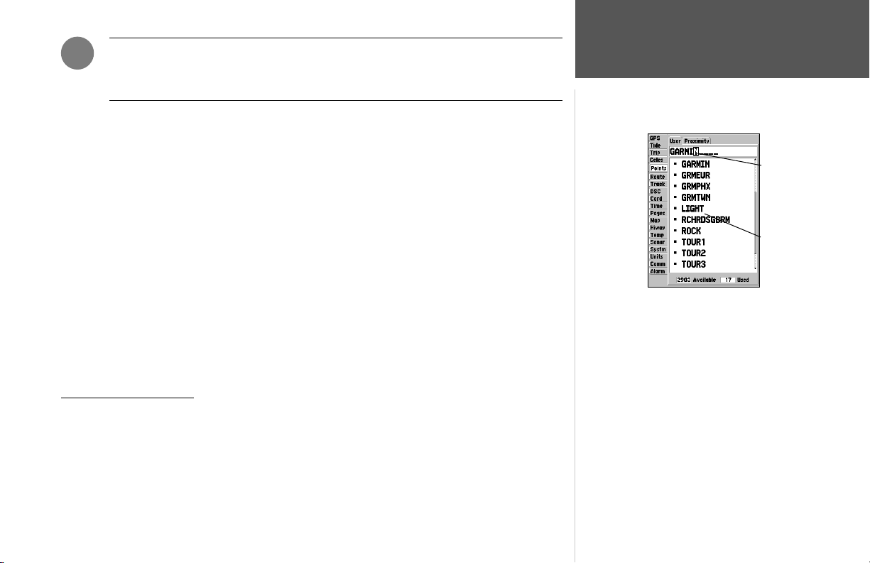
)
Once a waypoint is deleted from the list, it cannot be recovered from the unit. It is
advisable to backup important waypoints to a computer using an optional PC cable
and interface software, save them to a data card, or write them down by hand.
To delete an individual waypoint from the ‘User’ list:
1. Use the ARROW KEYPAD to highlight the waypoint to be deleted.
2. Press MENU, highlight ‘Delete Waypoint’ and press ENTER.
OR, press ENTER, highlight ‘Delete’ and press ENTER.
3. Press the ENTER key to confi rm the deletion warning.
To delete waypoints by symbol:
1. From the ‘User’ tab, highlight the waypoint to be deleted and press MENU, then select ‘Delete By
Symbol’ and press ENTER.
2. Use the ARROW KEYPAD to highlight the symbol of the waypoint(s) to be deleted and press
ENTER.
3. Press ENTER to confi rm. Choose ‘Cancel’ or press QUIT to stop the deletion.
To delete all user waypoints:
1. Press the MENU key to select the options window.
2. Use the ARROW KEYPAD to highlight ‘Delete All’ and then press ENTER.
3. Highlight the ‘OK’ prompt and press ENTER to confi rm.
Proximity Waypoint List
The ‘Proximity’ submenu of the Points tab lets you defi ne an alarm circle around a stored waypoint
position, and can be used to help you avoid reefs, rocks, or restricted waters. Up to ten waypoints may
be listed, with a maximum alarm radius of 99.99 nautical or statute miles or kilometers. If a proximity
alarm circle overlaps with an existing alarm circle, the message ‘Proximity Overlaps Another Proximity Waypoint’ appears. Since the unit will only alert for one of the overlap points, use caution when
You can also search for a waypoint by name:
1. Highlight the name fi eld and press ENTER.
2. Use the ARROW KEYPAD to select the fi rst letter of
the name.
3. Move to the RIGHT and enter the second letter if you do
not see it on the list below.
4. Repeat this until the name appears. Press ENTER when
you see the name.
5. Highlight the name on the list and press ENTER again
to review the waypoint. When done, highlight ‘OK’ and
press ENTER.
navigating in these areas. If you enter an alarm circle overlap, you will only be alerted to the closest
proximity waypoint.
Reference
Waypoint Lists
Name
Field
Waypoint
List
51
Page 62
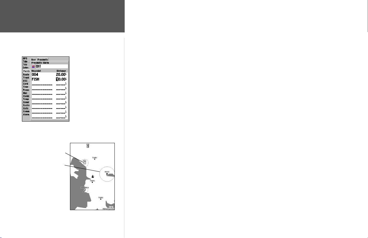
Reference
Waypoint Lists
Proximity Waypoint
Proximity Circle
A dashed circle appears
showing the alert boundary for the
proximity waypoints.
Proximity Waypoints List
To add a proximity waypoint:
1. Use the ARROW KEYPAD to highlight an empty space on the Proximity list and press ENTER. The
‘Find’ screen appears. Highlight ‘Waypoints’ and press ENTER.
2. Use the ARROW KEYPAD to highlight the desired waypoint from the ‘By Name’ or ‘Nearest’ tab
lists. The Waypoint Review page appears for the selected waypoint.
3. With ‘OK’ highlighted, press ENTER to confi rm. The distance fi eld is now highlighted.
4. Press ENTER to begin entry of the proximity radius.
5. Use the ARROW KEYPAD to enter a distance value (to 99.99 units) and press ENTER.
To turn proximity alarms on or off:
1. Use the ARROW KEYPAD to highlight the fi eld below “Proximity Alarm” and press ENTER.
2. Select the desired ‘ON’ or ‘OFF’ setting and press ENTER.
The following options are available from the ‘Proximity’ submenu of the ‘Points’ tab:
• Delete Alarm— removes selected waypoint from proximity list.
• Delete All— removes all waypoints from proximity list.
To display the waypoint menu options:
1. Using the ARROW KEYPAD, highlight the ‘Proximity’ tab and press MENU.
To clear one or all proximity waypoint(s) from the list:
1. Use the ARROW KEYPAD to highlight the proximity waypoint to clear and press MENU.
2. To clear a single alarm, highlight the ‘Delete Alarm’ option and press ENTER.
3. To clear all proximity waypoints, select the ‘Delete All’ option and press ENTER.
4. Use the ARROW KEYPAD to highlight the ‘OK’ prompt and press ENTER to confi rm.
52
Page 63
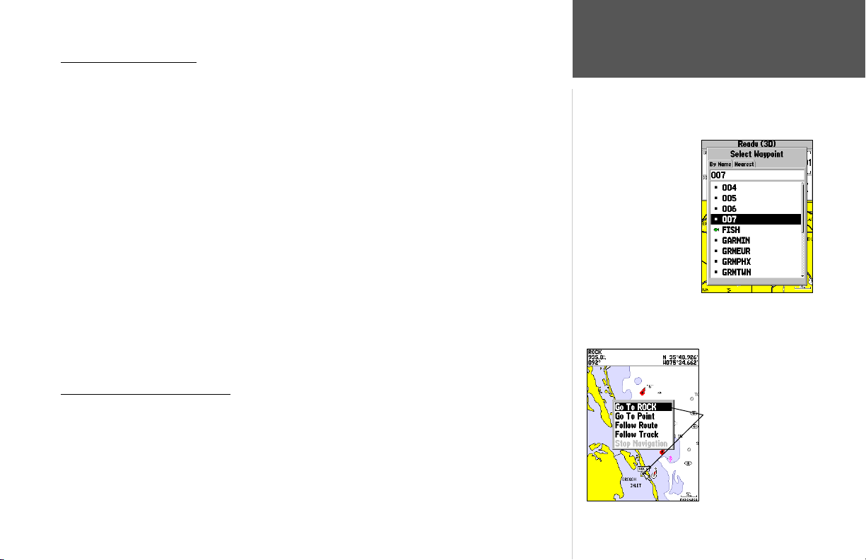
Going to a Destination
Using the NAV key, the GPSMAP 188/188C/238 Sounder provides three ways to navigate to a
destination: Go To Point, Follow Route, and Follow Track (TracBack). Once you are actively navigat-
Going to a Destination
ing, you will see a straight line that always runs from your current location to the destination on the
Map Page. The easiest method for selecting a destination is the ‘Go To’ function, which lets you select a
destination point, then quickly sets a direct course from your present position. If you highlight a point
on a list or the map and press NAV, ‘Go To <point name>’ appears in addition to ‘Go To Point’. The ‘Go
To’ function can be accessed from any list of points or graphically from the map display.
To activate a ‘Go To’ from a point list:
1. Press the NAV key.
2. Use the ARROW KEYPAD to highlight ‘Go To Point’ and press ENTER.
3. From the ‘Find’ menu, highlight ‘Waypoints’ and press ENTER. (You may also choose to go to other
points, such as Cities, Tide Stations, etc. from this list.)
4. Select a waypoint from the ‘By Name’ or ‘Nearest’ list, then press ENTER. To display the Waypoint
Review page for the selected waypoint.
5. With the ‘Go To’ button highlighted, press ENTER to begin navigation.
To stop navigation:
1. Press the NAV key. Use the ARROW KEYPAD to highlight ‘Stop Navigation’ and press ENTER.
Choose a waypoint
from either the ‘User’
or ‘Nearest’ tab list.
Selecting a ‘Go To’ Graphically
A graphical ‘Go To’ may be used to select one of three items from the map display: an existing
waypoint, an on-screen map item (roads, rivers, cities, navaids, etc.), or a new map point (non-map
item). If you select a map item as the ‘Go To’ destination, the GPSMAP 188/188C/238 Sounder will
automatically use the name of the map item, but the point will not be stored in the waypoint list (see
page 45 for creating waypoints using map items). If you select a new map point (non-map item) as the
‘Go To’ destination, the GPSMAP 188/188C/238 Sounder automatically creates or moves a waypoint
named ‘MAP’ at the cursor position.
Reference
The waypoint or map item
name will automatically
appear when highlighted
and NAV is pressed.
53
Page 64
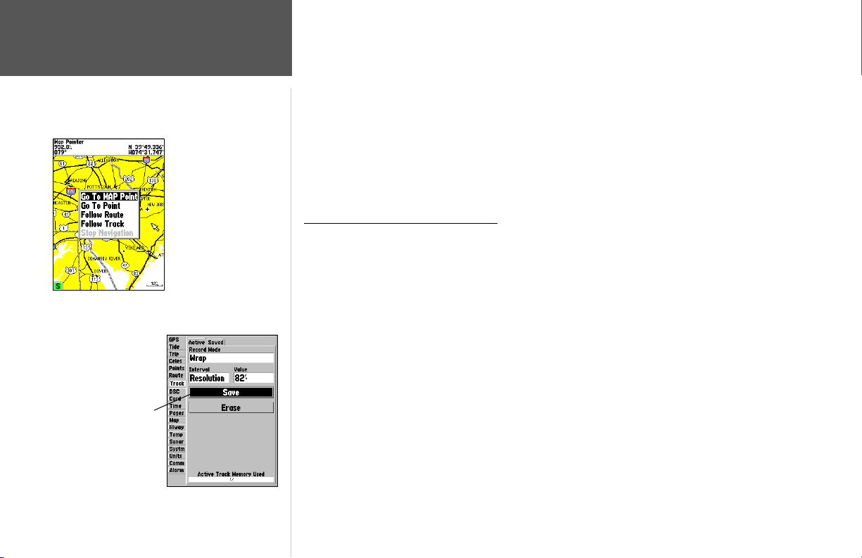
Reference
Going to a Destination/
TracBack Navigation
Highlight ‘Save’ and press
ENTER to save an active
track log.
54
‘Go To MAP Point’ allows
you to navigate to a spot
on the map that is not a
waypoint or map item.
To activate an existing waypoint or map item as a ‘Go To’ from the map display:
1. Use the ARROW KEYPAD to highlight the waypoint or map item on the screen and press NAV.
2. With ‘Go To <waypoint name>’, press ENTER.
To activate a new map point (non-map item) as a ‘Go To’ from the map display:
1. Use the ARROW KEYPAD to move the arrow cursor to the desired position and press NAV.
2. With ‘Go To MAP Point’ highlighted, press ENTER.
To stop navigation:
1. Press the NAV key. Use the ARROW KEYPAD to highlight ‘Stop Navigation’ and press ENTER.
TracBack Navigation (Follow Track)
The TracBack function allows you to retrace your path using the track log automatically stored in
the receiver’s memory, which eliminates the need to store waypoints along the way. TracBack routes are
created by reducing your track log into a route of up to 50 turns and activating an inverted route along
those points. Once activated, a TracBack route leads you back to the oldest stored track log point, so it’s
a good idea to clear the existing track log before you start your current trip.
To clear the track log and defi ne a starting point for a TracBack route:
1. Press MENU twice to display the Main Menu page.
2. Using the ARROW KEYPAD, highlight the ‘Track’ tab, then highlight the ‘Active’ tab to the right.
3. Use the ARROW KEYPAD to highlight ‘Erase’ and press ENTER.
4. Highlight ‘OK’ and press ENTER.
You must fi rst save the track log before you can use the ‘Follow Track’ feature. The Save feature
allows you to store up to 15 track logs from certain times and dates.
To save a track log:
1. From the Main Menu, use the ARROW KEYPAD to highlight the ‘Track’ tab, then highlight the
‘Active’ tab to the right.
Page 65
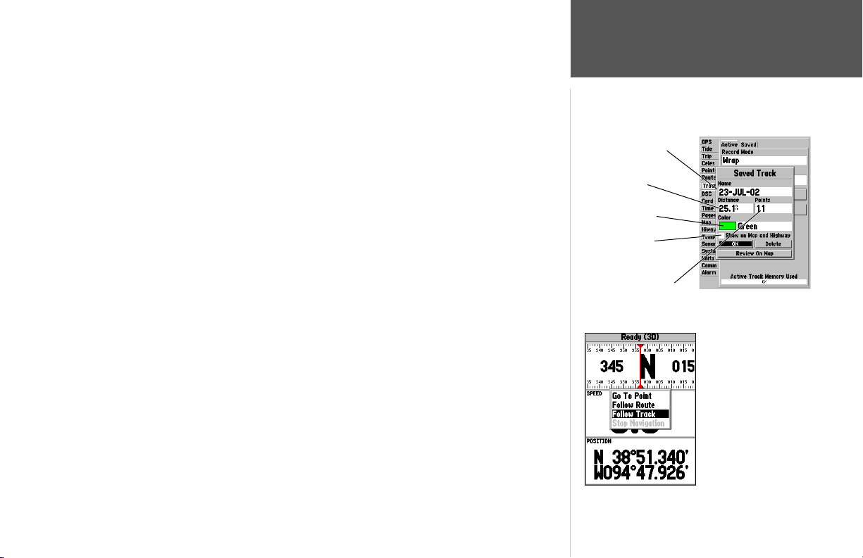
2. Use the ARROW KEYPAD to select ‘Save’ and press ENTER.
3. On the ‘Save Back Through’ window, highlight the desired time, date, or ‘Entire Log’ and press
ENTER.
4. Next, the track will begin saving and then display the ‘Saved Track’ window when done. The default
name, distance and number of points (500 max) will be displayed.
To change the name of the saved track, highlight the name fi eld and press ENTER, make your
changes and press ENTER again.
To choose a style (monochrome units) or color (color models) that will be used to display the saved
track line, highlight the fi eld and press ENTER, choose a Color or Style and press ENTER again.
To display the track on the Map and Highway pages, highlight the check box to the left of ‘Show on
Map and Highway’ and press ENTER.
To view the track on the map, highlight ‘Review on Map’ and press ENTER. Press QUIT to exit the
Track Map window.
5. Highlight ‘OK’ and press ENTER to save the track.
To activate a TracBack using the NAV key:
1. Press the NAV key, then highlight the ‘Follow Track’ option and press ENTER.
2. Highlight the track you wish to follow and press ENTER.
3. Choose either ‘Original’, which will navigate you from the start to the end of your trip, or ‘Reverse’,
which will navigate you from the end to the start of your trip and press ENTER.
Once a TracBack has been activated, the GPSMAP 188/188C/238 Sounder will take the track
log currently stored in memory and divide it into segments called ‘legs’. Up to 254 temporary ‘turns’
(BEGIN, TURN 1, TURN 2, TURN 3,...., TURN X, END) will be created to mark the most signifi cant
features of the track log in order to duplicate your exact path as closely as possible. To get the most out
of the TracBack feature, remember the following tips:
• Always clear the track log at the point that you want to go back to (dock, etc.).
• The ‘Record Mode’ option on the track log setup page must be set to ‘Fill’ or ‘Wrap’.
• There must be at least two track log points stored in memory to create a TracBack route.
Reference
TracBack Navigation
Default Track name
Total Distance
Change color or
style of track line
Check this box to
display track
Total number of points
You must fi rst save a track
before using the ‘Follow
Track’ option. If there are
no saved tracks, the
message “There are no
saved Tracks to follow”
appears after you select
‘Follow Track.’
55
Page 66
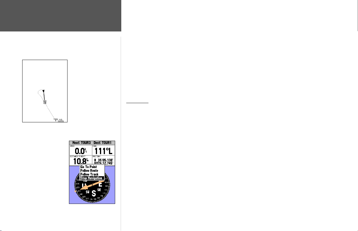
Reference
TracBack Navigation/
MOB: Man OverBoard
Highlight ‘Stop
Navigation’ and
press ENTER to
stop navigating.
The MOB function allows
you to quickly activate a
course back to a location.
• If the track log interval is set to the ‘Time’ option, the route may not follow your exact path (keep
the interval set to ‘resolution’ for best performance).
• If the receiver is turned off or satellite coverage is lost during your trip, the TracBack will draw a
straight line between any point where coverage was lost and where it resumed.
• If your track log’s changes in distance and direction are too complex, 254 waypoints may not mark
your path accurately. The receiver then assigns the 254 waypoints to the most signifi cant points of
your track, and simplifi es segments with fewer changes in direction.
To stop TracBack navigation:
1. Press the NAV key, highlight ‘Stop Navigation’ and press ENTER.
For more information on setting up the Track options and saved tracks, see pages 75-76.
MOB Key
The GPSMAP 188/188C/238 Sounder’s Man OverBoard function (MOB) lets you simultaneously
mark and set a course to a position for quick response to emergency situations.
To activate the MOB function:
1. Press the MOB key.
2. Press ENTER to confi rm and begin navigating to the MOB position.
Once a MOB has been activated, a ‘MOB’ waypoint with an international MOB symbol is created
and the unit is set on an active navigation to that point. Use any of the Navigation Pages to guide you
back to the MOB point. The MOB waypoint is stored in the waypoint list and may be deleted like any
other waypoint (see page 50).
To stop navigation to the MOB position:
1. Press the NAV key, highlight ‘Stop Navigation’ and press ENTER.
56
Page 67
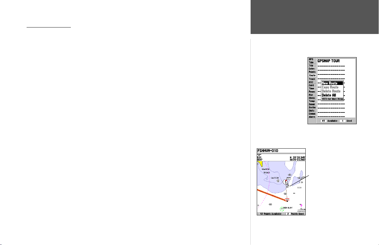
Creating a Route
The last way to navigate to a destination is to create a user-defi ned route. The Garmin GPSMAP
188/188C/238 Sounder lets you create and store up to 50 reversible routes (numbered 1-50), with up
to 254 waypoints each. Routes can be created in two ways. The fi rst way is by selecting points from
the Map Page, allowing you to see each route graphically on-screen as you create the route. The second
way is to select waypoints from the Find menu, allowing you to see a list of the route points as you
create the route. To create a route, start by accessing the Main Menu.
To create a route graphically:
1. Press the MENU key twice to display the Main Menu page. Use the ARROW KEYPAD to highlight
the ‘Route’ tab.
2. Press the MENU key to display the route options page. Select ‘New Route’ and press ENTER.
Or, highlight the fi rst available blank slot in the Route List and press ENTER.
3. To add an existing waypoint or map item to the route, use the ARROW KEYPAD to highlight
the desired waypoint or map item on screen and press ENTER. Map items will not appear in the
waypoint list. To create a waypoint from a map item, see page 45.
4. To add a new waypoint to the route, use the map cursor to select the desired map position and
press ENTER. Press ENTER again to confi rm the new waypoint. You may also change the name,
symbol and other properties of the new waypoint (see pages 48-49).
As you add each new waypoint to the route, the data window at the top of the map display will
show the waypoint/map item name, bearing and distance from your location, and coordinates of
the cursor. The bottom of the display will show you the number of available and used points. A
route line appears on the map to indicate each completed leg, and a dotted line appears to indicate
the distance and bearing to the arrow cursor from the last route waypoint.
5. Repeat steps 3 and 4 until you have fi nished defi ning all route waypoints.
6. When fi nished press QUIT twice to return to the Route List page; or press MENU, highlight ‘Edit as
Text’ and press ENTER to return to the Route Review page.
Reference
Creating a Route
Main Menu—Route Tab
and Route Options Menu
You will see ‘ADD’
below the cursor as
you add points.
57
Page 68
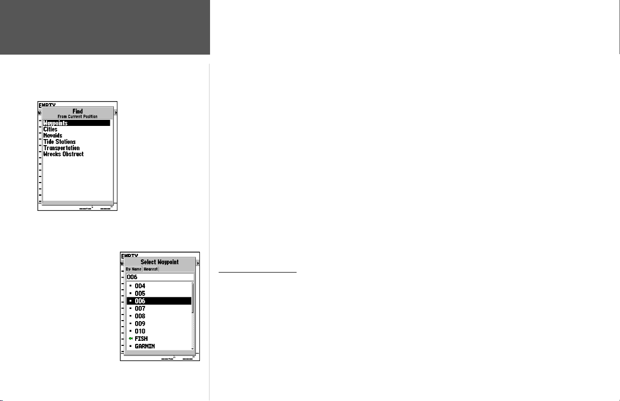
Reference
Creating a Route/
Following a Route
Choose a waypoint from
either the ‘By Name’ or
‘Nearest’ tab list.
58
Choose the type of point
you want to add to the
route.
To create a route using text:
1. Press the MENU key twice to display the Main Menu page. Use the ARROW KEYPAD to highlight
the ‘Route’ tab.
2. Press the MENU key to display the route options page. Select the ‘New Route’ option and press
ENTER.
Or, highlight the fi rst available blank route slot and press ENTER.
3. Press MENU, select ‘Edit as text’ and press ENTER.
4. Use the ARROW KEYPAD to highlight the fi rst fi eld under the word “Waypoint” and press
ENTER.
5. From the Find menu, highlight ‘Waypoints’ and press ENTER. (You may also choose from other
points, such as Cities, Tide Stations, etc. from this list.) Select a waypoint from either the “By Name”
or “Nearest” list and press ENTER. (See page 45 for searching for waypoints by name.)
6. On the Point Review or Waypoint Review page, ‘OK’ is automatically highlighted. Choose ‘Show
Map’ and press ENTER to view the point on the map, then press QUIT to return to the Waypoint/
Point Review page. With ‘OK’ highlighted, press ENTER to add the point to the route.
7. Repeat steps 4-6 until the desired route points have been entered. Press QUIT to return to the
Route List page.
Following a Route
Once a route has been created, it can be activated and used for navigation with the NAV key. A
route may be followed in the same sequence as it was originally created, or inverted and followed from
the end point back to the beginning point.
To activate and follow a route:
1. From any page, press the NAV key, then using the ARROW KEYPAD, highlight ‘Follow Route’ and
press ENTER. (If you highlight a route from the Route List or Route Review page and press NAV,
the window will automatically display, ‘Follow <the route name>’.)
Page 69
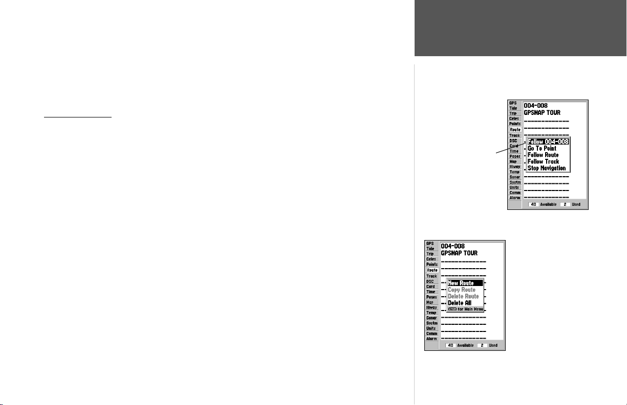
2. Highlight the route you wish to navigate and press ENTER.
3. Choose ‘Activate’ or ‘Invert and Activate’ and press ENTER. (‘Activate’ will use the route as is,
‘Invert and Activate’ will reverse the route then activate it.)
To deactivate (stop navigation) of a route:
1. Press the NAV key, highlight ‘Stop Navigation’ and press ENTER.
Route List Page
The GPSMAP 188/188C/238 Sounder Route List page (‘Route’ tab of the Main Menu) displays
all the routes currently stored in memory, along with a descriptive name for each route. By pressing
MENU while on the Route List page, the following menu options appear: ‘New Route’ (page 57), ‘Copy
Route’, ‘Delete Route’, or ‘Delete All’.
If you highlight a route
name from the Route List
and press NAV, the name
will automatically appear.
To select and follow a route:
1. On the Route List page, use the ARROW KEYPAD to highlight the desired route and press NAV.
2. With ‘Follow <route name>’ highlighted, press ENTER. Highlight ‘Activate’ or ‘Invert and
activate’ and press ENTER.
To deactivate (stop following) the route:
1. Press the NAV key, highlight ‘Stop Navigation’ and press ENTER.
To copy or delete a route:
1. From the Route List, using the ARROW KEYPAD, highlight the route you want to copy or delete
and press MENU.
2. Choose either ‘Copy Route’ or ‘Delete Route’ and press ENTER and with ‘OK’ highlighted, press
ENTER again to confi rm a deletion. Copy will use the same route name with an additional number,
starting at 1, at the end of the route name.
To delete all routes:
1. From the Route List, press MENU.
2. Highlight ‘Delete All’ and press ENTER. With ‘OK highlighted, press ENTER again to confi rm.
Reference
Route List Page
Route List Options Menu
59
Page 70
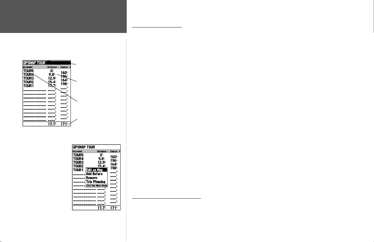
60
Reference
Route Review Page
Route Name
Data Fields
Route Points
Data Totals
Route Review
Options Menu
Route Review Page
Once you have created a route, the Route Review page allows you to edit a selected route.
To access the Route Review page:
1. Press MENU twice and highlight the ‘Route’ tab.
2. Highlight the name of the route you wish to review and press ENTER.
The Route Review page also allows you to enter a 15-character name for any listed route. By
default the name includes the fi rst and last waypoints in the route.
To enter a custom route name:
1. From the Route Review page, highlight the name fi eld and press ENTER to begin editing.
2. Use the ARROW KEYPAD to enter the desired name and press ENTER when fi nished.
Once you are on the Route Review page, you may review the route points (waypoints or map
items) one at a time from the list.
To review individual route points:
1. Highlight the desired point and press ENTER.
2. On the Point Review window, you may choose ‘Next’ (highlight the next point on the route list),
‘Show Map’ (show the point on a map window), or ‘Delete’ (permanently delete the waypoint from
the unit) and press ENTER. If the route point is a user waypoint, you may edit any of the waypoint
properties on the Waypoint Review page (see pages 48-49 for details).
Once you are back on the Route Point List, the next point in the route is automatically highlighted.
This allows you to review each point on the route by repeatedly pressing ENTER.
Route Review Options Menu
By pressing MENU on the Route Review page, the following options are available: Edit on Map,
Add Before, Remove, and Trip Planning.
Page 71
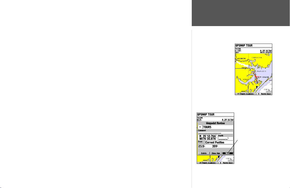
• Edit on Map — review and modify the route displayed for each point (waypoint or map item)
on a map page. You may also use the cursor to insert a new route point on a route leg, review the
waypoint or map item.
To edit a route on the map:
1. From the Route Review page, press MENU, highlight ‘Edit on Map’ and press ENTER.
To review a route point:
1. Highlight the point and press ENTER. The Review page appears. Highlight ‘Next’ and press ENTER
to return to the map with the next route point highlighted.
To edit a route point:
1. Use the ARROW KEYPAD to highlight the desired route waypoint and press MENU.
A pop-up menu of editing choices appears, with the following options: Edit as Text (return to the
Route Review page), Remove, Move (user waypoints only), and Add.
To remove a route waypoint:
1. Highlight the ‘Remove’ option and press ENTER.
To move a route waypoint:
1. Highlight the ‘Move’ option and press ENTER.
2. Move the cursor to the new map position and press ENTER.
To add points to the beginning or end of the route:
1. With the map cursor, select the fi rst route waypoint (to add waypoints to the beginning of the
route) or last (to add waypoints to the end of the route) and press MENU.
2. Highlight the ‘Add’ option and press ENTER.
3. Move the cursor to the new point or position and press ENTER.
4. If you are not adding an existing waypoint, press ENTER to confi rm the new waypoint.
5. Repeat steps 3 and 4 to add additional waypoints or press QUIT to fi nish.
Reference
Editing Routes
Highlight a route point
and press ENTER to
review it.
Choose ‘Next’ to center
the map on the next point
in the route. You can
step through the points
by repeatedly pressing
ENTER.
61
Page 72
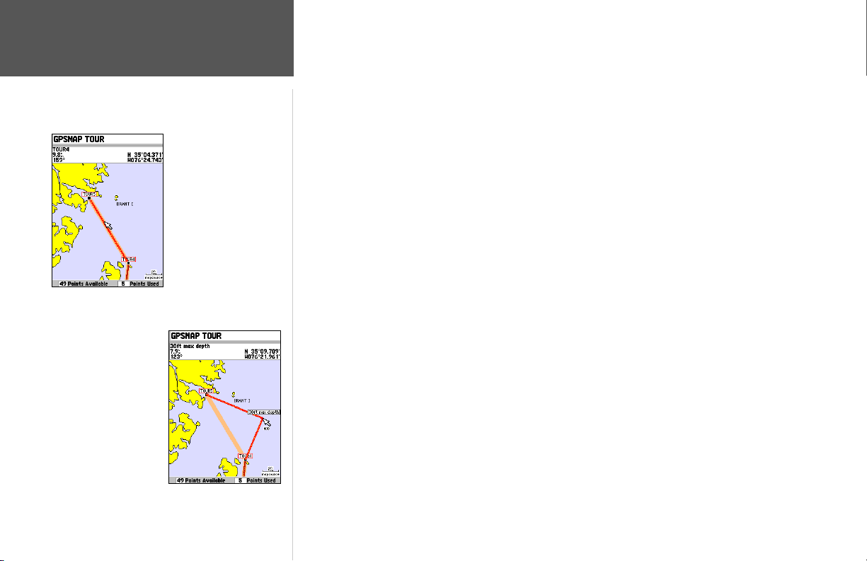
Reference
Editing Routes
Drag the route leg to
an existing waypoint,
map item, or an
open spot on the map
(shown) to create a
new route point.
Highlight the route leg
on which you wish to
insert a waypoint and
press ENTER.
The GPSMAP 188/188C/238 Sounder’s route edit mode also allows you to insert a new route point
in any route leg using the map cursor.
To insert a new point between two existing route waypoints:
1. Use the ARROW KEYPAD to select the leg in which you want to insert the new waypoint (the
route line will highlight and change to a dotted line when the leg is selected) and press ENTER.
2. Move the cursor to the new map position, existing waypoint, or map item (You will see ’ADD’
below the arrow and the route lines will move with the arrow) and press ENTER.
3. If you are not inserting an existing point, press ENTER to confi rm the new waypoint.
4. Press QUIT to return to the Route Review page.
• Add Before — Insert a waypoint into the route points list.
To insert a point into the route:
1. From either the Route Review or Active Route pages, use the ARROW KEYPAD to highlight the
point you wish to insert the new point before and press MENU.
2. Highlight ‘Add Before’ and press ENTER.
3. From the ‘Find’ menu, highlight ‘Waypoints’ and press ENTER. (You may also choose from other
points, such as Cities, Tide Stations, etc. from this list.) Select the point you want and press ENTER
twice. (See page 51 for searching for waypoints by name.)
• Remove — Remove a point (waypoint or map item) from a route. This option is available from both
the Route Review and Active Route Pages.
To remove a point from a route:
1. From either the Route Review or Active Route pages, use the ARROW KEYPAD to highlight the
point to remove and press MENU.
2. Highlight ‘Remove’ and press ENTER.
62
Page 73
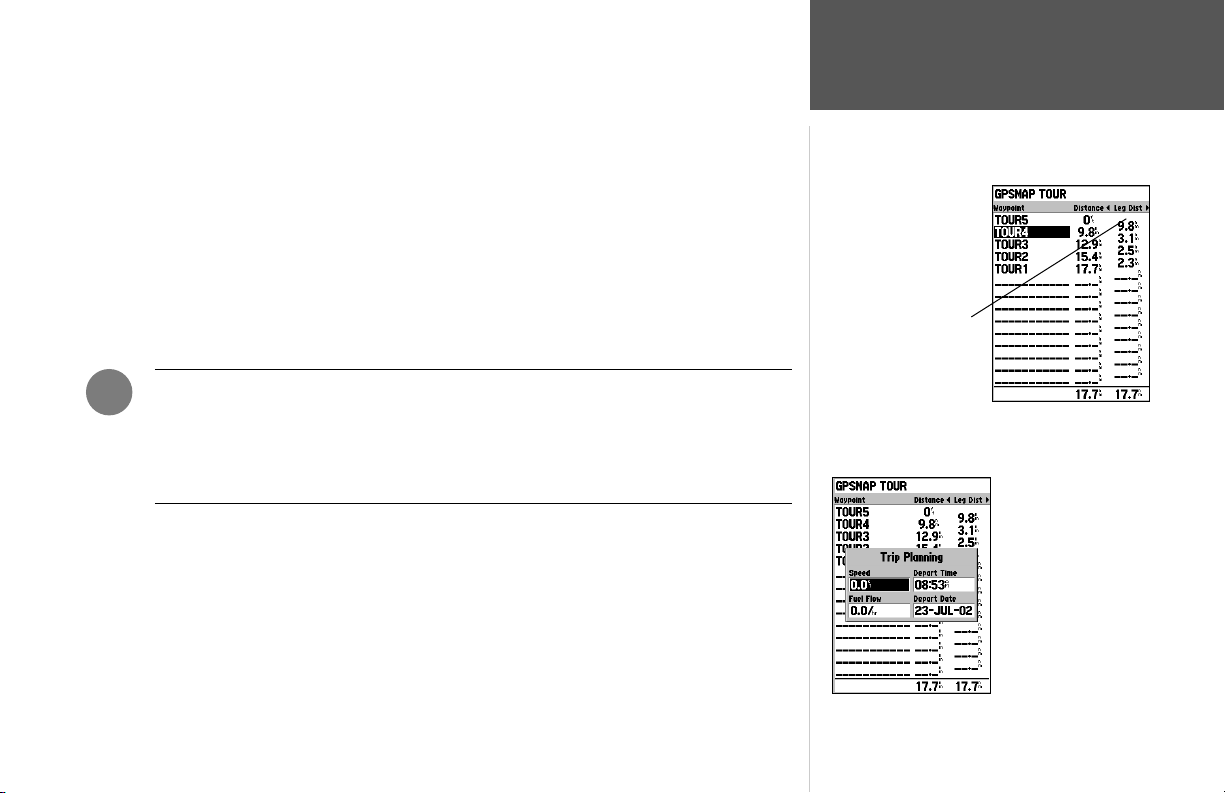
• Trip Planning — The Route Review and Active Route pages also display trip-planning information
for each leg or the entire route. Available information includes Course, ETA, Fuel (to point), Leg
Distance, Leg Fuel, Leg Time, Sunrise and Sunset (at point location) and Time To (point).
To use the trip planning feature:
1. Highlight the desired route from the Route List and press ENTER to display the Route Review page.
2. One of nine available planning fi gures appears to the right of each route waypoint and its distance.
Use the LEFT/RIGHT keys on the ARROW KEYPAD to select the desired item.
3. To enter planning information (from the Route Review Page only), press MENU and select ‘Trip
Planning’ from the options list. Enter the fi gures for Speed, Fuel Flow, Departure Time, and
Departure Date.
4. Press QUIT to return to the Route Review Page.
Press LEFT or RIGHT on
the ARROW KEYPAD to
change the data fi eld.
Reference
Editing Routes
)
NOTE: Fuel fl ow rates on your unit are measured in “units per hour”. System setting
changes for units of measure (statute, nautical or metric) do not affect the fuel fl ow
measure. You should enter fuel fl ow rates based upon available information for your
vehicle (operator’s manual, performance specifi cations, etc.) and make note of the
desired units of measure (gallons, liters, etc.).
Trip Planning
Data Fields
63
Page 74
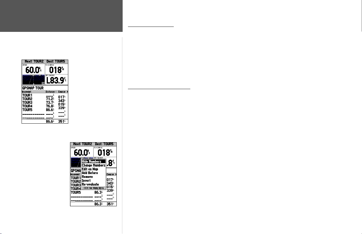
Reference
Active Route Page
Active Route Page
Whenever you have activated a route in the GPSMAP 188/188C/238 Sounder, the Active Route
page shows each point (waypoint or map item) of the active route, with the point name, distance and
choice of Course, ETA, Fuel to point, Leg Distance, Leg Fuel, Leg Time, Sunrise and Sunset at point
location, or Time To point for each point from your present position. The current destination point,
the ‘active’ point, is marked with an arrow icon. As you navigate a route, the point list automatically
updates to indicate the next ‘active’ point fi rst. The Active Route and Route Review pages share many of
the same features and options.
Active Route Page
Menu Options
64
Active Route Page
Active Route Page Options
The following options are available by pressing MENU on the Active Route page:
• Hide/Show Numbers — see page 26 and 28 for instructions.
• Change Numbers — see pages 26-28 for instructions.
• Edit on Map — see pages 61-62 for instructions.
• Add Before — see page 62 for instructions.
• Remove — see page 62 for instructions.
• Invert — reverses the direction of the route.
• Re-evaluate — recalculates and reactivates the current route data. Selects the route leg closest to
your current position as the active leg (the active leg defi nes the current ‘from’ and ‘to’ waypoints).
To invert an active route:
1 From the Active Route page, press MENU.
2. Using the ARROW KEYPAD, highlight ‘Invert’ and press ENTER to reverse the route.
To re-evaluate an active route:
1 From the Active Route page, press MENU.
2. Using the ARROW KEYPAD, highlight ‘Re-evaluate’ and press ENTER/MARK to recalculate.
Page 75
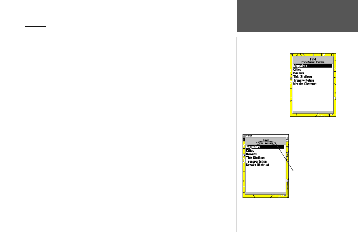
Find Key
The FIND key allows you to search the units for user waypoints, map items, and any optional
BlueChart or MapSource information loaded on a data card. Press the FIND key to search for items
from your current location by default. You may also search from other locations. When you press FIND,
a list of available items to search from appears. The default items are Waypoints, Cities, Tide Stations,
and Transportation. Additional items, such as Anchorages, Businesses, Exits, Navaids, Restricted Areas,
Wrecks, Obstructions, etc., are displayed depending on the optional BlueChart or MapSource data card
inserted into the unit. If you pan around on the Map Page and press FIND, the unit centers its search
from the point where the cursor is located. When using BlueChart or MapSource data, your position or
the map pointer must be within the map outline area to search for information from that area.
To fi nd a waypoint or other item from your current location:
1 From any page, press FIND.
2. Using the ARROW KEYPAD, highlight the desired category from the list and press ENTER.
3. For Waypoints and Cities, you may search using ‘By Name’ or’ Nearest’. Use the ARROW KEYPAD
to highlight the desired tab. For ‘By Name’, you may use the top fi eld to spell out the name or scroll
down through the list.
To fi nd a waypoint or item from another location:
1. Once the search results list is displayed for a particular item, press MENU.
2. Highlight ‘Nearest to Other’ and press ENTER. If you are actively following a route, you may also
choose ‘Nearest to Next’ or ‘Nearest to Destination’.
3. Select a reference point on the map and press ENTER. The search results list will change to list items
nearest to the new map position.
To fi nd a waypoint or item from another location on the map:
1 From the Map Page, use the ARROW KEYPAD to pan to the desired location and press FIND.
2. Using the ARROW KEYPAD, highlight the desired category from the list and press ENTER.
Reference
Find Key
Find Items List
From the Current
Location
You may also start a
‘Find’ from items found
on the Find List or from
another location on the
map.
65
Page 76
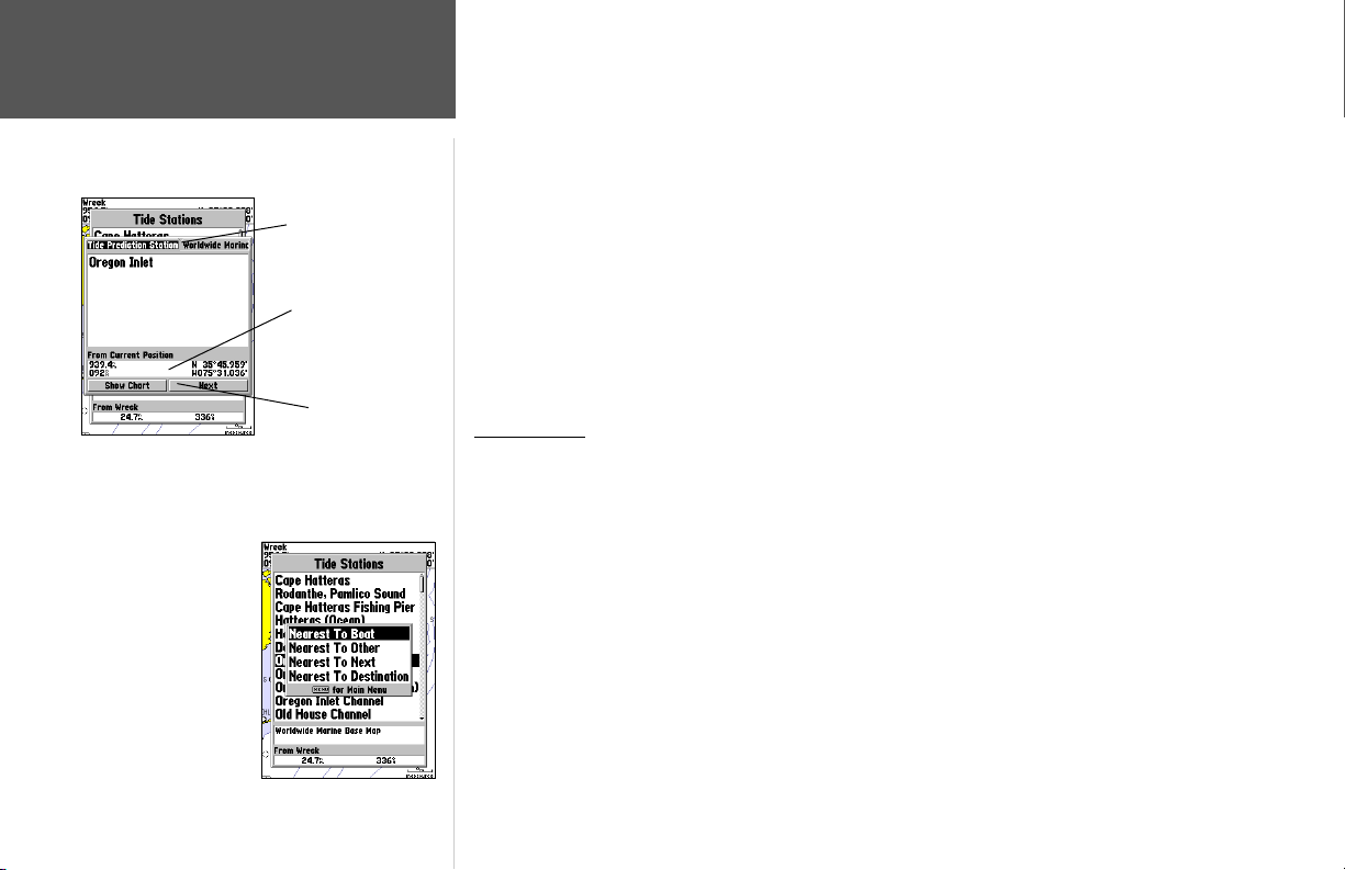
Reference
Find Options
Additional Information Window
Find Menu Options
Additional Information
Tabs
Distance, Bearing,
Coordinates of item
Additional Option
Buttons
To view details about an item:
1. With the desired item highlighted in the search results list, press ENTER.
2. An Information page appears with details about the item organized in a tabbed format. Depending
on the type of item, additional options are available for viewing the item on the map, viewing notes
on a MapSource or BlueChart map, viewing a tide chart, viewing a list of maps on your data card,
and viewing the next item in the search results list.
The Find option supports a “fi nd from” feature, which allows you to center your search around
an item that you have just found. For example, you search for “Restricted Areas” and the search shows
an “Anchoring Prohibited” search result. If you press FIND again, you will see “From Anchoring
Prohibited” as the new search from point. You may also use the Find feature to center your search from
any waypoint, route list entry, map item or tide station. Highlight the item you want to Find ‘from’, and
press the FIND key.
Find Options
Using the Find options, you may search from various map data and utilize variety of nearest
criteria for all items, except waypoints. Available Find options are:
• Nearest To Boat— centers search from your boat’s current location
• Nearest To Other— allows you to choose another map location from which to search.
• Nearest To Next— centers search from the next point of your active route.
• Nearest To Destination— centers search from the last point of your active route.
To fi nd an item using the fi nd options:
1 From any page, press FIND.
2. Using the ARROW KEYPAD, highlight the desired category from the list and press ENTER.
3 From the search results list, press MENU, then highlight the desired option and press ENTER.
66
Page 77
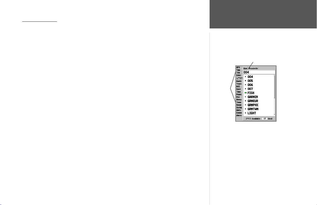
Main Menu Page
The GPSMAP 188/188C/238 Sounder’s Main Menu Page provides access to various waypoint,
system, navigation and interface management, and setup menus in an easy to use “tab” format. The
Main Menu page is available from any page in the GPSMAP 188/188C/238 Sounder’s system, and is
accessed through the MENU key. See pages 2-3 for additional instructions changing settings and entering data.
To access the Main Menu Page:
1. Press MENU twice. The 19 Menu tabs are divided into categories by function.
To select a Menu tab from the Main Menu page:
1. Move the ARROW KEYPAD UP or DOWN to highlight the tab you want to view. The information
for the highlighted tab will automatically appear to the right. If you want to highlight any of the tab
items, press to the RIGHT on the ARROW KEYPAD, then move UP or DOWN to select individual
items.
2. Press either MENU for additional submenu options or press ENTER/MARK to make changes to the
highlighted item. Press LEFT on the ARROW KEYPAD to get back to the Menu tab list. Press QUIT
to return to the Main Menu page.
Main
Menu
Tabs
The Main Menu tabs are:
• GPS – shows satellite status, accuracy, initialize position.
• Tide – shows 24 hour tide chart with levels and times.
• Trip – provides trip speeds, odometers, averages, and trip timers.
• Celes – shows sun/moon time cycles and positions.
• Points – allows you to create, edit or delete waypoints. See pages 50-52.
• Route – allows you to create, edit, activate or delete routes. See pages 57-63.
• Track – lets you record a track, defi ne how it is recorded and displayed.
• DSC— allows you to control the Digital Selective Calling (DSC) interface.
• Card – interface control for saving waypoints, routes and tracks to a data card
• Time – sets up time format, time zones, and daylight savings. (continued)
.
Reference
Main Menu Page
Submenu Tabs
Main Menu Page
67
Page 78
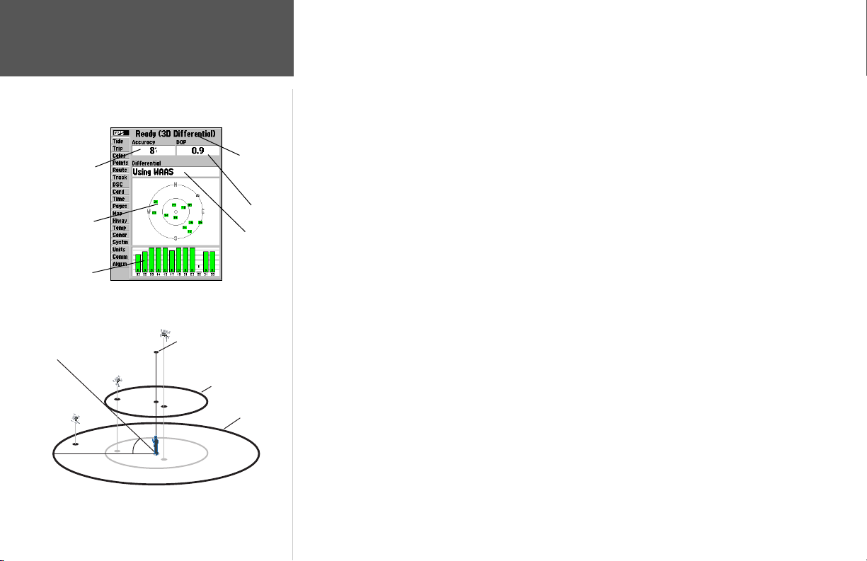
Accuracy
n
Sky View
Signal
Strength
Bars
68
Reference
Main Menu: GPS Tab
Main Menu— GPS Tab
Center dot - 90°
above the horizon
90°
Inner ring- 45°
above the horizon
45°
Receiver
Status
DOP
Differential
Status
Outer ring
the horizo
• Pages – enables main pages to be shut off, turned on, or ‘jumped to’.
• Map – sets up Map Page features, zooms, and text size. See pages 29-32.
• Temp – sets up and shows the water temperature log.
• Hiway – sets up Highway Page features. See pages 42-43.
• Sonar – sets up Sonar Page features, speeds and calibrations. See pages 38-40.
• Systm – defi nes beeper and simulator, restores setup, and displays software version.
• Units – defi nes position format, datum, heading, and distance and speed units.
• Comm – interface settings for use with a PC or second device.
• Alarm – sets up alarms for anchor drag, arrival, off course, and clock.
GPS Tab— provides a visual reference of satellite acquisition, receiver status, and accuracy. The status
information will give you an idea of what the receiver is doing at any given moment. The sky view and
signal strength bars give you an indication of what satellites are visible to the receiver and whether or
not they are being tracked. The signal strength is shown on a bar graph for each satellite, with the satellite number below. As the receiver locks onto satellites, a signal strength bar appears for each satellite in
view. The progress of satellite acquisition is shown in three stages:
• No signal strength bars— the receiver is looking for the satellites indicated.
• Light/White signal strength bars— the receiver has found the satellite(s) and is collecting data.
• Dark/Green signal strength bars— the receiver has collected the necessary data and the satellite(s)
are ready for use.
As soon as the GPSMAP 188/188C/238 Sounder has collected the necessary data from the best
satellites in view to calculate a fi x, the status fi eld will indicate a 2D or 3D status. The unit will then
update the position, date and time.
You can use the sky view to help determine if any satellites are being blocked, and whether you
have a current position fi x (indicated by a ‘2D’,‘2D Differential’,‘3D’, or ‘3D Differential’ in the status
fi eld). The sky view shows a bird’s-eye view of the position of each satellite relative to the receiver’s
last known position. The outer circle represents the horizon (north up), the inner circle 45º above the
horizon, and the center point a position directly overhead. You can also set the sky view to a ‘Track Up’
confi guration, causing the top of the sky view to align along your current track heading.
Page 79
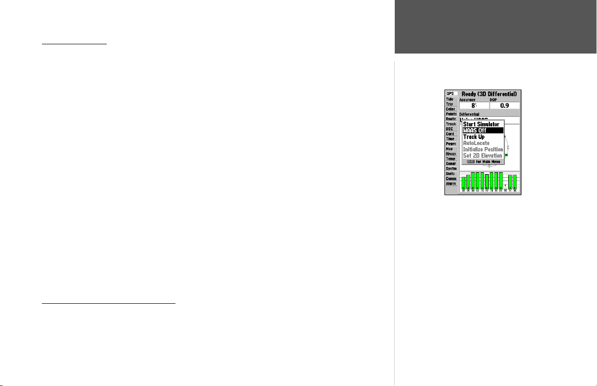
WAAS Capability
The GPSMAP 188/188C/238 Sounder is capable of receiving WAAS (Wide Area Augmentation
System) satellite signals. WAAS is an FAA (Federal Aviation Administration) funded project to improve
Main Menu: GPS Tab
the overall accuracy and integrity of the GPS signal for aviation use, but land/sea based users may also
benefi t from this system. At this time, the system is still in the development stage and is not fully operational. There are currently two WAAS satellites that can be received in the U.S.A., one over the Atlantic
Ocean and one over the Pacifi c Ocean, in a geo-stationary orbit over the equator. Effective use of the
WAAS satellite signal may be limited by your geographic location in relation to those satellites, now in
developmental service. WAAS satellite signal reception requires an absolute clear view of the sky and
works best when there are no nearby obstructions such as buildings, mountains, etc. WAAS satellites
will be numbered 33 or higher when viewing the sky view on your GPSMAP 188/188C/238 Sounder.
Initial reception of the WAAS signal may take up to 15-20 minutes, then 1-2 minutes afterwards. When
WAAS differential correction has been received for GPS satellites (numbers 32 or below), a ‘D’ appears
in the signal bar of the sky view and ‘2D or 3D Differential’ appears in the receiver status. To learn more
about the WAAS system, its satellite positions and current state of development, visit the FAA web site
(http://gps.faa.gov). Since WAAS requires CPU resources of the GPSMAP 188/188C/238 Sounder to
Highlight ‘WAAS Off’ and press ENTER
to disable the WAAS capabilities.
search for and track the satellites, you may disable the WAAS feature to improve unit performance if
WAAS reception is not available in your area.
To disable/enable WAAS capability:
1. From the GPS tab, press MENU, then use the ARROW KEYPAD to highlight ‘WAAS Off’ or ‘WAAS
On’ and press ENTER.
Receiver Status, Accuracy and DOP
Receiver status is indicated at the top fi eld of the page, with the current Accuracy and Dilution Of
Precision (DOP) to the right of the sky view. DOP is an indication of satellite geometry quality measured on a scale of one to ten (lowest numbers the best, highest numbers the poorest). Accuracy uses
DOP and other factors to calculate horizontal position accuracy in feet or meters.
Reference
69
Page 80
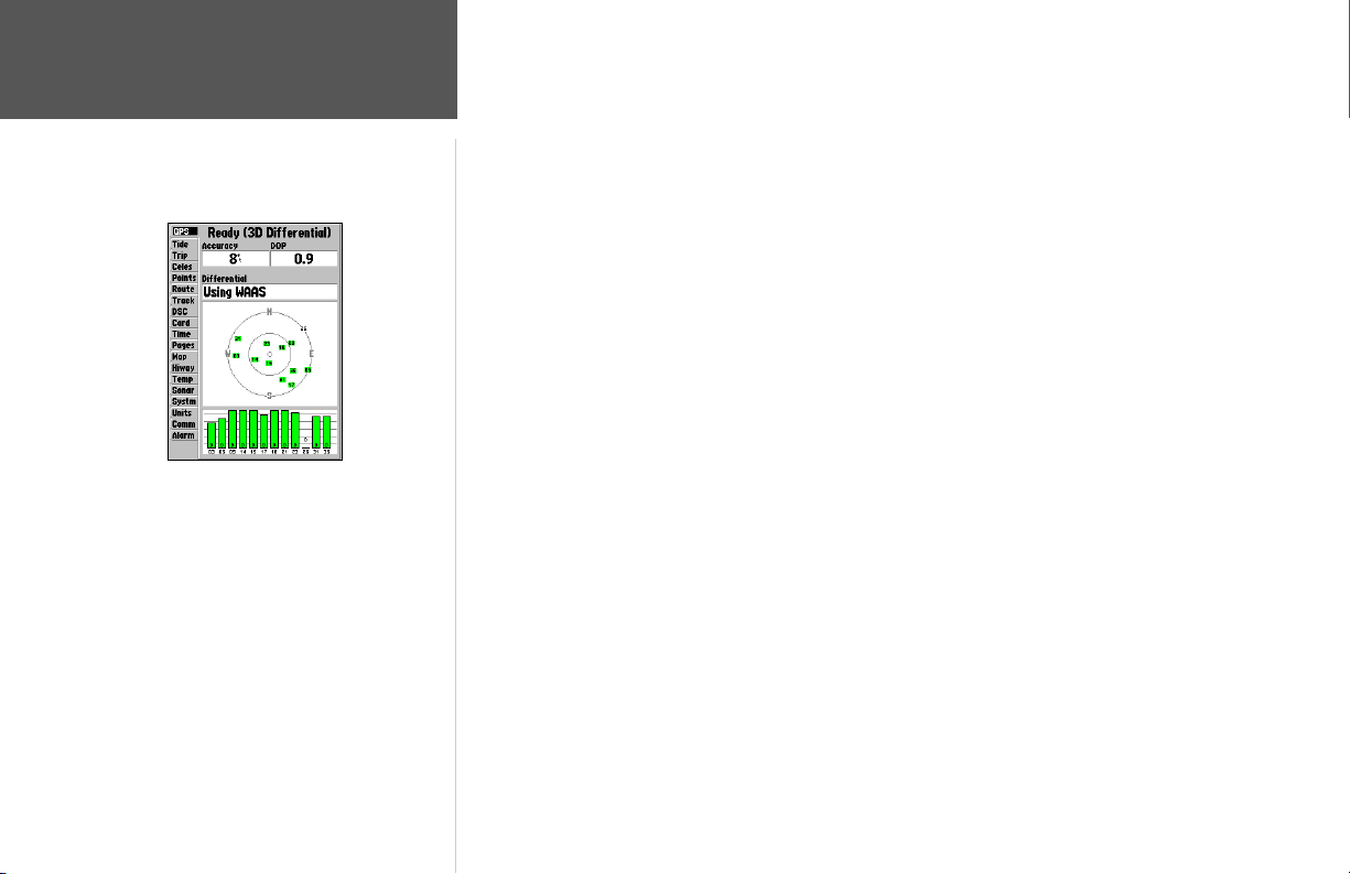
Reference
Main Menu: GPS Tab
When the GPSMAP 188/188C/238 Sounder is
using a differential correction signal (either WAAS
or DGPS), a “D” is displayed at the bottom of the
signal strength indicator bars for the satellites that
are corrected.
70
The status fi eld will show one of the following conditions:
• Looking For Satellites – the receiver is looking for any satellites.
• AutoLocate – the receiver is looking for any satellite whose almanac has been collected. This
process can take up to fi ve minutes.
• Acquiring Satellites – the receiver is looking for and collecting data from satellites visible at its last
known or initialized position, but has not collected enough data to calculate a fi x.
• 2D – at least three satellites with good geometry have been acquired and a 2 dimensional position
fi x (latitude and longitude) is being calculated. ‘2D Differential’ appears when you are receiving
DGPS corrections in 2D mode and a ‘D’ will show on the strength bar of satellites being corrected.
• 3D – at least four satellites with good geometry have been acquired and your position is now being
calculated in latitude, longitude and elevation. ‘3D Differential’ appears when you are receiving
DGPS corrections in 3D mode and a ‘D’ will show on the strength bar of satellites being corrected.
• Poor GPS Coverage – the receiver is no longer tracking enough satellites for a 2D or 3D fi x.
• Receiver Not Usable – the receiver is unusable, possibly due to interference or abnormal satellite
conditions. Turn the unit off and back on to reset.
• Simulating – the receiver is in simulator mode.
The Differential Receiver status will show one of the following:
• Off – No optional beacon receiver attached or enabled in the Comm menu or WAAS Off
• Searching For WAAS – WAAS is enabled and receiver is searching for WAAS signal
• Using WAAS – WAAS capability enabled and unit receiving WAAS corrections
• No Beacon Signal – DGPS receiver attached, but not transmitting RTCM data to GPS
• Tuning Beacon – Receiver is tuning manual DGPS frequency
• Receiving Beacon – Unit is receiving DGPS corrections
• Scanning Beacon – DGPS receiver is scanning for available frequency
• Using DGPS – Indicates a Differential signal is being received (only displays when the Serial Data
Format is set to “Other DGPS” on the Comm Tab of the Main Menu)
Page 81
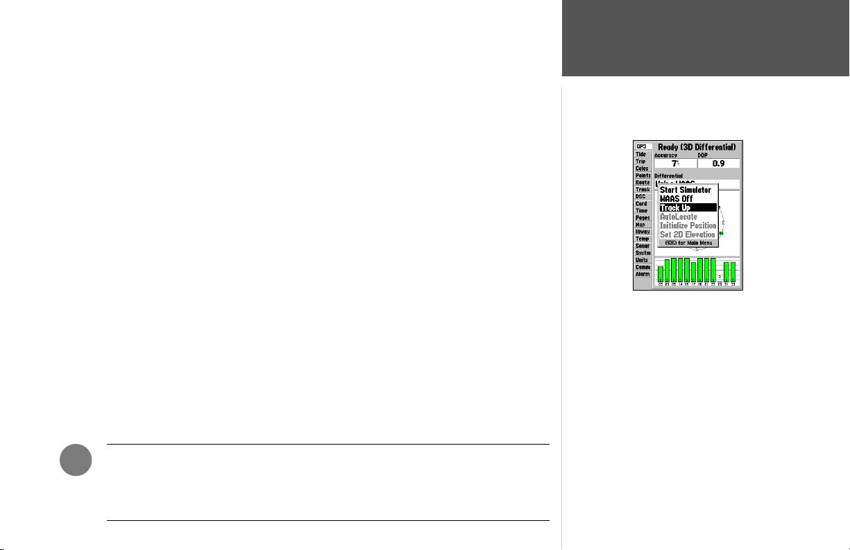
The Differential SNR (Signal to Noise Ratio) indicates, on a scale to 0-30db with 30db being the
best, the strength of the DGPS signal being received. If no optional DGPS receiver is used with the
GPSMAP 188/188C/238 Sounder, the ‘DGPS Rcvr’ fi eld displays ‘Off. The SNR will depend upon the
mounting of your DGPS receiver and the distance from the DGPS transmitting station.
The GPS Info tab features an options menu that provides access to functions and features relating
to the GPS Info display.
The following options are available by pressing MENU on the GPS Info Tab of the Main Menu:
• Start/Stop Simulator— toggles the unit simulator on or off. Retail Demo mode will restore factory
settings to the unit if left unattended for over 2 minutes. This mode should only be used for display
purposes. User waypoints will NOT be deleted.
• WAAS On/WAAS Off— toggles the WAAS capability of the receiver on or off.
• Track Up/North Up— allows you to select between a north up or track up sky view display for the
GPS Info display only.
• AutoLocate— allows the receiver to locate your position automatically. This process can take up to
fi ve minutes.
• Initialize Position— allows you to initialize the receiver graphically on the Map Page to initially
help the receiver acquire more quickly. See pages 4-5 for instructions on initialization.
• Set 2D Elevation— allows you to manually enter the elevation when in 2D or Simulator mode only.
Any elevation entered will be automatically calculated when the GPS is in 3D mode.
To select a menu option:
1. Using the ARROW KEYPAD, highlight the desired option and press ENTER.
Reference
Main Menu: GPS Tab
GPS Tab Options Menu
)
NOTE: If a DGPS receiver is attached to the unit and Garmin DGPS, RTCM In/NMEA
Out, or Other DGPS is enable on Port 2, WAAS will be automatically disabled (WAAS
Off). It is not possible for the GPSMAP 188/188C/238 Sounder to receive WAAS and
DGPS corrections at the same time.
71
Page 82
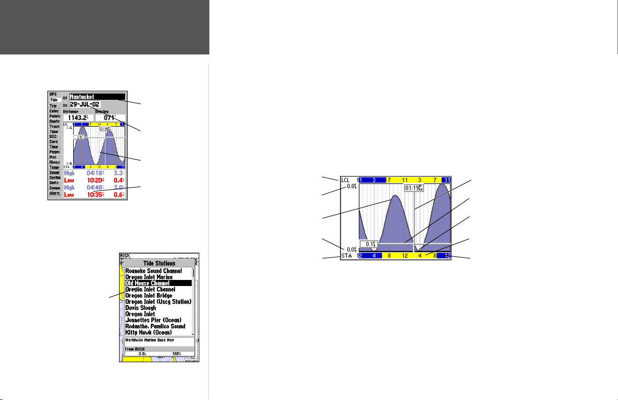
Reference
Main Menu: Tide Tab
Station Name
Date
Tide Chart
Tide Tab— shows a graphical chart that displays tide station information in a 24-hour span starting at
midnight station time. You can choose from different dates and over 3000 tide stations around the USA
coastline, Alaska, Hawaii, western Canada and several of the Caribbean islands.
The top of the page displays the tide station being referenced, below that the date. The top of
the chart shows a 24-hour block of local time (LCL) for your position, with the reported station time
(STA) appearing at the bottom. Daylight (light/yellow bar) and nighttime (dark/blue bar) show across
the time scale, with the time progressing from left to right. (Local time scales and sunrise/sunset info
may not be available for a few stations). The solid, light vertical lines are in 4-hour increments, and the
light, dotted vertical lines are in 1-hour increments. A solid, vertical line (with the current time box at
the top) will indicate the time of day when using current date and will intersect the tide graph to show
their relation.
Main Menu—Tide Tab
You can select from a list
of nearest stations.
72
Event Times
Local Time
Max. Level
High Tide Curve
Min. Level
Station Time
Current Time Bar
Current Tide Height Bar
Low Tide Curve
Day
Night
The tide curve shows as a shaded area, with higher tides being taller and lower tides shorter. The
solid, horizontal line (with the current tide box on the left) indicates the current tide height. The fi gure
to the left of the line will show the current tide level in feet. The Mean Lower Low Water (MLLW)
appears as a solid, horizontal line near the bottom of the chart (This line will only appear if the tide
ranges to the zero value or below). The numbers directly below/above ‘LCL’ and ‘STA’ indicate the
maximum/minimum levels, respectively. The four data fi elds below the chart, indicate event times and
levels at which the tide changes starting in the upper left fi eld, going downward, then to the upper
right and down again.
Page 83
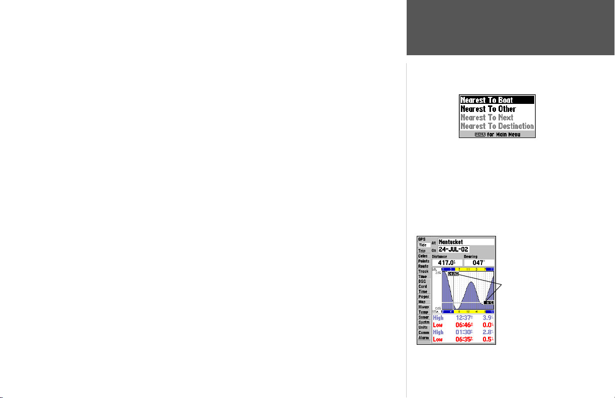
To view the chart for a tide station nearest to your current location:
1. From the Tide tab, highlight the ‘At’ fi eld and press ENTER.
2. Press MENU, select ‘Nearest to Boat’ and press ENTER.
3. Select the desired station from the list and press ENTER.
4. Highlight ‘Show Chart’ or ‘OK’ and press ENTER.
If you are not within this range, you will see a message “None Found”. Use the ‘Nearest To Other’
Find option and select a location closer to a tide station.
To fi nd the chart for a tide station nearest to a location on the map:
1. On the Map Page, press FIND, then select ‘Tide Stations’ and press ENTER.
2. Press MENU, select ‘Nearest To Other’ and press ENTER.
3. Use the ARROW KEYPAD and the ZOOM IN/ZOOM OUT keys to select a position on the map
and press ENTER.
4. Highlight the desired station from the list and press ENTER to view the information page for that
chart (this shows the station’s distance and bearing from the selected map location, along with the
station’s position coordinates).
5. Highlight ‘Show Chart’ and press ENTER.
To view the tide chart for another date:
1. With a chart displayed for the desired station, highlight the ‘On (date) fi eld and press ENTER.
2. Enter the desired date with the ARROW KEYPAD and press ENTER.
3. To return to the current date, press MENU, highlight ‘Use Current Date’ and press ENTER.
To view a chart’s details for another time of day:
1. With the desired chart displayed, press MENU, select ‘Move Cursor’ and press ENTER.
2. Press the ARROW KEYPAD LEFT or RIGHT to view the chart at a different time
3. To return to the current time, press MENU, highlight ‘Stop Moving Cursor’ and press ENTER.
Reference
Main Menu: Tide Tab
Tide Station List Menu Options
Press MENU on the Tide Station list to access additional
search options. The ‘Nearest to Next’ and ‘Nearest to Destination’ options are enabled when you are actively going to a
destination (following a Go To or a Route, for example). You
must select a location within 100 nm. of a tide station.
You may move the
cursor to see tide
heights at different
times. Tide data will
show in a black box
when in cursor mode.
73
Page 84
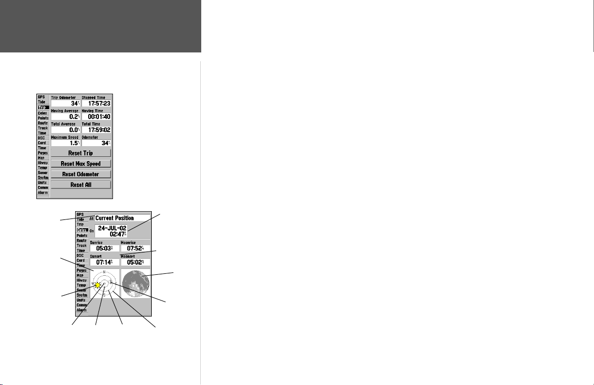
Reference
Main Menu: Trip Tab/
Celestial Tab
Position
Skyview
Window
Sun
Position
45°Overhead (90°)
74
Main Menu— Celestial Tab
Main Menu— Trip Tab
Date/Time
Sun/Moon
Event Times
Moon
Position
Horizon (0°)20°
Moon
Phase
Trip Tab— displays Trip Odometer, Moving Average Speed, Total Average Speed, Maximum Speed,
Stopped Time, Moving Time, Total Time, and Odometer.
To reset the trip data:
1. Highlight ‘Reset Trip’, ‘Reset Max Speed’, ‘Reset Odometer’ or ‘Reset All’ and press ENTER.
Celes (Celestial) Tab— displays celestial data for sun and moon rise/set, moon phase, and approximate skyview location of the sun and moon. The moon phase displays the current visible portion of the
moon as a light color. You may display this data for your current position, a position from the map, or
a Find item location. Also, you may select a different date and time, or use the current data.
To choose another position:
1. From the Celestial tab, highlight the ‘At’ fi eld and press ENTER.
2. The Find menu appears. Make a selection and press ENTER until the information for that location
is displayed on the Celestial tab. See pages 65-67 for more information on using the Find feature.
List highlight any category, except Other Location, and press ENTER. If you wish to reference a Find
item, select from the Find list, and press ENTER.
The location the unit is using appears in the ‘At’ fi eld. The timetables displayed will be based upon
your current time zone. When using a position from another location outside of your time zone, you
will need to set the Time Zone for that location in the Time tab of the Main Menu (see page 77).
To change the time or date:
1. From the Celestial tab, use the ARROW KEYPAD to highlight the date or time fi eld and press
ENTER.
2. Enter a new date or time and press ENTER.
3. To return to the current date and time, press MENU, use the ARROW KEYPAD to highlight ‘Use
Current Date and Time’ and press ENTER.
To change the skyview orientation:
1. From the Celestial tab, press MENU, then use the ARROW KEYPAD to highlight ‘North Up’ or
‘Track Up’ and press ENTER.
Page 85
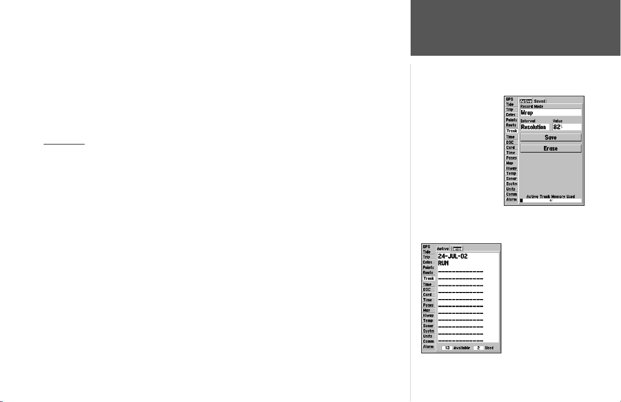
Points Tab— contains the ‘User’ and ‘Proximity’ waypoint lists. See pages 50-52.
Route Tab— contains a list of available routes. See pages 57-63.
Track Tab— lets you specify whether or not to record a track log (an electronic ‘breadcrumb trail’
recording of your path), defi ne how it is recorded, or save track log data for future use. The Track Tab
also provides an indicator of the memory used for the active track log and options to clear the track
memory or start a TracBack route. See pages 54-56 for TracBack information. The Track submenu is
divided in two tabs: ‘Active’ tab and the ‘Saved’ tab.
Active Tab
The ‘Active’ tab is for the active log (the log currently being recorded). It displays track memory
used and current settings. For the ‘Active’ tab, the following settings are available:
• Record Mode— lets you select one of three track recording options:
Off— No track log will be recorded. Note that selecting the ‘Off’ setting will prevent you from
using the TracBack feature.
Fill— a track log will be recorded until the track memory is full.
Wrap— A track log will be continuously recorded, wrapping through the available memory
(replacing the oldest track data with new data).
• Interval— defi nes the frequency at which the track plot is recorded. Three interval settings are available:
Distance— records track based on a user-defi ned distance between points.
Time— records track plot based on a user-defi ned time interval.
Resolution— records track plot based upon a user-defi ned variance from your course over
ground. The resolution option is the default setting and is recommended for the most effi cient
use of memory and TracBack performance. The distance value (entered in the value fi eld) is the
maximum error allowed from the true course before recording a track point.
Reference
Main Menu: Track Tab
Main Menu—
Active Track Tab
Main Menu—
Saved Track Tab
75
Page 86
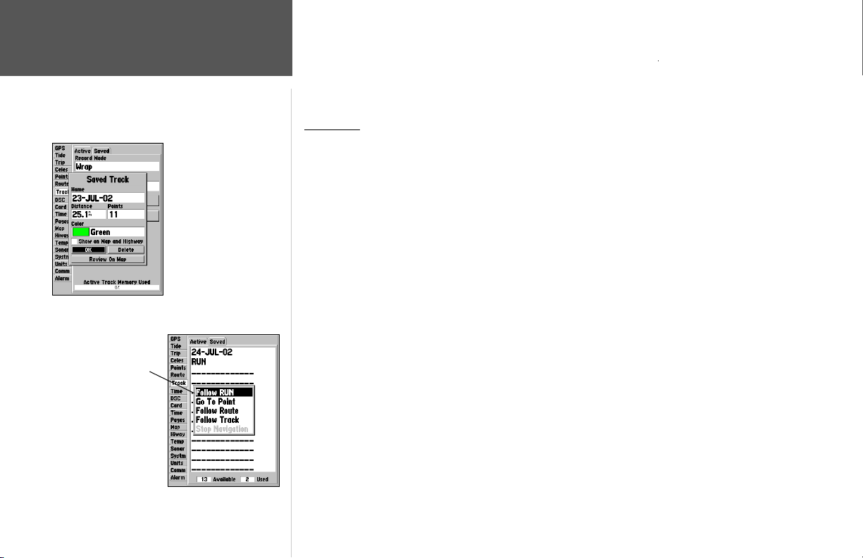
Reference
Main Menu: Track Tab
The track name will automatically appear when
highlighted on the ‘Saved’
list and NAV is pressed.
76
Reviewing a saved track
• Value— defi nes the distance or time used to record the track log.
• Save— allows you to save the current active track log.
• Erase— allows you to clear the active track log currently stored in memory.
Saved Tab
The ‘Saved’ tab displays and manages a list of any saved track logs, allows TracBack activation, map
display of saved logs. The active log stores up to approximately 2500 track log points, based upon the
criteria specifi ed in the Track settings. Up to 15 track logs may be saved in memory, with up to 500
track log points in each saved log.
On the ‘Saved’ tab, the following options are available by highlighting a track and pressing MENU:
• Review On Map – displays the saved track log on a Track Map page.
• Delete Track – deletes highlighted saved track log from memory.
• Delete All – deletes all saved track logs from memory.
To review and edit a track:
1. On the ‘Saved’ Track tab of the Main Menu, highlight the desired track and press ENTER. The Saved
Track window appears.
2. You may rename the track, choose to show the track on the Map and Highway pages, delete the
track, or view the track on a map window.
3. To exit, press QUIT or highlight ‘Next’ and press ENTER.
You may also activate a TracBack from any of the saved tracks on this tab.
To activate a TracBack from the ‘Saved’ tab list:
1. Using the ARROW KEYPAD, highlight the track you wish to use for a TracBack and press NAV.
2. The ‘Follow <track name>’ will automatically appear highlighted. Press ENTER.
3. Choose either ‘Original’, which will navigate you from the end to the start of your trip, or ‘Reverse’,
which will navigate you from the start to the end of your trip and press ENTER.
Page 87
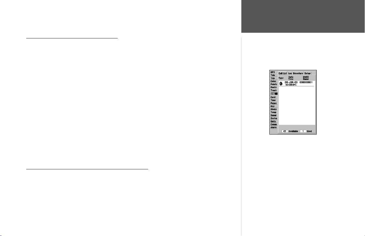
DSC Tab— allows to control and set up DSC (Digital Selective Calling) features on the unit.
Reference
What is Digital selective calling (DSC)?
Digital Selective Calling (DSC) uses marine VHF radio and Global Positioning System (GPS) technologies to transmit and receive location information. DSC is used by mariners to assist them in two major
areas: Distress Calls and Position Reporting.
An emergency DSC Distress Call allows a vessel in trouble to transmit a substantial amount of information in a single transmission or “call,” without the need for voice communication. When any nearby
rescuer receives the DSC signal, an alarm sounds and they immediately receive the position of the caller.
The rescuer may then choose to navigate (Go To) the caller’s position to assist or forward the call on
to the Coast Guard. When the Coast Guard receives the call, they can immediately access the caller’s
information (such as who they are and the type of vessel) in their database while they are in transit to
the caller’s position.
A non-emergency DSC Position Report allows mariners to exchange and display the positions of one
another. Once a DSC position is received, the mariner may choose to create a waypoint or to show the
received position on an electronic map.
Any time a vessel receives a DSC call, they can store that location and quickly navigate to that position
using a Go To. This makes DSC a time-saver, especially in an emergency situation. In order to use DSC,
users must fi rst register their VHF radio with the FCC and receive a Maritime Mobile Service Identity
(MMSI) number.
What is A Maritime mobile service identity (MMSI)?
Maritime Mobile Service Identity (MMSI) basically allows a VHF radio to act like a phone. In order to
make a “call” on a phone, you fi rst need a phone number to dial. The 9-digit MMSI number acts like
a phone number when used in a Position Report and as a unique identifi er to the Coast Guard when
used in an emergency Distress Call. In order to to obtain a Maritime Mobile Service Identity (MMSI)
number, users must register their VHF radio with the FCC (Form 605). Garmin does not supply this
number!
Main Menu: DSC Tab
DSC Tab
77
Page 88

78
Reference
Main Menu: DSC Tab
HOW ARE MMSI ASSIGNMENTS OBTAINED?
Non-commercial users (e.g. recreational users who remain in domestic waters and only carry VHF,
EPIRB (Emergency Position Indicating Radio Beacons), and Radar) are not required to have a FCC
ship station license. The FCC and Coast Guard have authorized some second and third party vendors
to assign MMSI numbers. This service is limited to registering recreational vessels only. To receive
information on how to obtain a recreational MMSI number please contact: http://www.uscg.mil/
rescue21/links/mmsi.htm or http://wireless.fcc.gov/marine/.
U.S Non-Federal User: Commercial users, or those who travel outside the U.S. or Canada, must
apply for a ship station license, or an amendment to a ship station license. To fi nd out if you require
a Ship Station license contact: http://wireless.fcc.gov/marine/fctsht14.html. If your vessel requires
licensing by the FCC you will obtain a MMSI during the application/licensing process when you fi le
FCC Forms 159 and 605.
U.S. Federal User: Federal users can obtain MMSI assignments from their agency radio spectrum
management offi ce. These procedures are currently under review by the NTIA (National Telecommunications and Information Administration).
Outside the U.S.: Users can obtain an MMSI assignment from their telecommunications authority
or ship registry, often by obtaining or amending their ship station license.
In Canada: Industry Canada is responsible for assigning MMSI numbers to commercial and
recreational vessels. Information is available at the following web site: http://apollo.ic.gc.ca/english/
mmsi.html.
For more information regarding MMSI’s visit: http://www.navcen.uscg.gov/marcomms/gmdss/
mmsi.htm.
HOW CAN GARMIN HELP YOU WITH DSC?
To receive Distress Calls or Position Reports, you must have a DSC-equipped chartplotter as well as a
VHF radio with DSC support. During normal, non-emergency Position Report communication, Channel
70 (156.525 MHz) has been set aside as the VHF/DSC digital call channel. For a Distress Call, a mariner
presses the MayDay button on their VHF radio. The call transmits on an emergency channel with the
Page 89
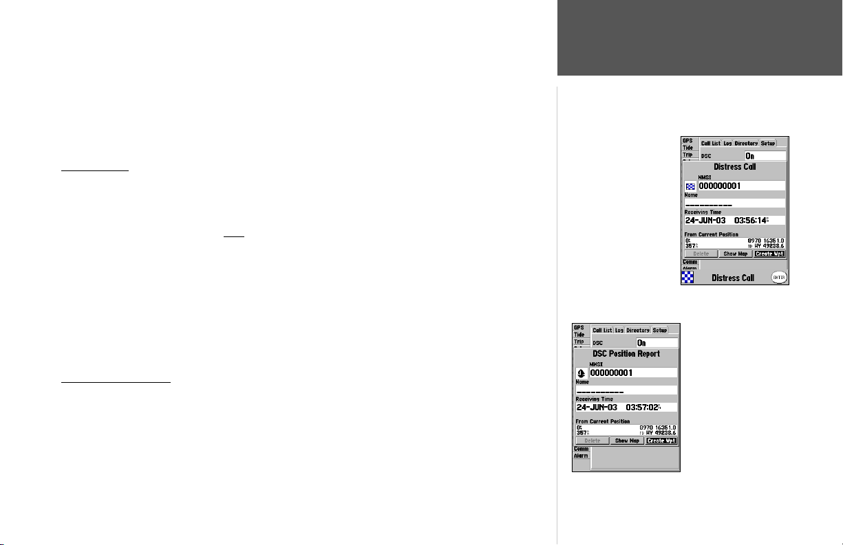
MMSI number attached to the call (if you have DSC support). Any DSC-equipped mariner (on sea or
land) within range can receive the call.
When the Garmin GPSMAP 188/188C/238 is connected to a VHF with DSC support, the GPS unit
displays a Call List, Log, and a Directory available to store incoming information received from another
user’s DSC capable VHF/GPS combination. Basic wiring is required for the Garmin unit and VHF radio
to send and receive NMEA data from each other (pg.87).
Distress Call
With a Garmin DSC capable chartplotter/sounder properly connected to a VHF radio with DSC
output, you may receive any DSC Distress Call within range. A window will pop up and a message
displays when a Distress Call is received. To notify you a Distress Call has been received, an alarm
will sound (if enabled). The alarm only
sounds on a Distress Call, and it will not sound on a Position
Distress Call Message
Report. Distress Calls are broadcasted to all DSC users in radio range.
Options available from this screen are:
• Show on Map: If you immediately wants to see the caller’s position they select ‘Show on Map’.
• Create Waypoint: If you want to create a waypoint of that posistion, highlight ‘Create Waypoint’
and press ENTER/MARK.
You also have the ability to input a caller’s name, if it is known. (The caller’s name replaces the
MMSI number as a reference once it is entered.)
DSC Position Report
The Position Report operates similarly to the Distress Call. Remember this type of contact is like a
phone call, but no emergency alarms are set off and the call is specifi c to the receiver. Position Reports
are not broadcasted to all DSC users.
Reference
Main Menu: DSC Tab
Position Report Message
79
Page 90
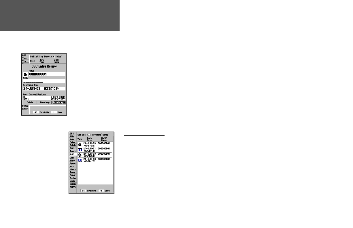
Reference
Main Menu: DSC Tab
DSC Entry Review
DSC Log
DSC Call List
The DSC Call List displays the current calls received. The GPS can manage up to 50 calls. When
‘calls’ are received, they are updated constantly to give the most current information, even if the unit is
left unattended. Any entry from the Call List can be selected to show an Entry Review.
DSC Log
When DSC calls are received, they are automatically stored in the Log, with the latest call at the top.
The unit may store up to 100 logs. Once 100 logs are received, the oldest log fi le is removed when a
new call is received. The Log displays information of call Type, Date/Time, Position, and MMSI/Name.
Pressing MENU from this page allows you to ‘Sort By Time’, ‘Sort By Name’, ‘Sort By (Call) Type’,
‘Delete’ (only after highlighting a particular call), and ‘Delete All’.
To Review a Call:
1. From the DSC tab of the Main Menu and the Log or Call List tab highlighted, press DOWN Arrow
Keypad until the call you want to review is highlighted.
2. Press ENTER/MARK to select the call.
DSC Entry Review
The DSC Entry Review operates similarly to the Distress Page and Position Report Page. This page
has the additional option to ‘Delete’ the displayed call. From the DSC Entry Review, you can ‘Delete’ the
entry, ‘Show on map’, or ‘Create Waypoint’.and create a name for the entry.
DSC Directory
The DSC Directory acts much like a phone book. A user can save up to 50 contacts. The directory
lists by Name and MMSI number. Pressing MENU from this page allows you to create a ‘New Item’,
‘Delete Item’, or ‘Delete All’.
80
Page 91
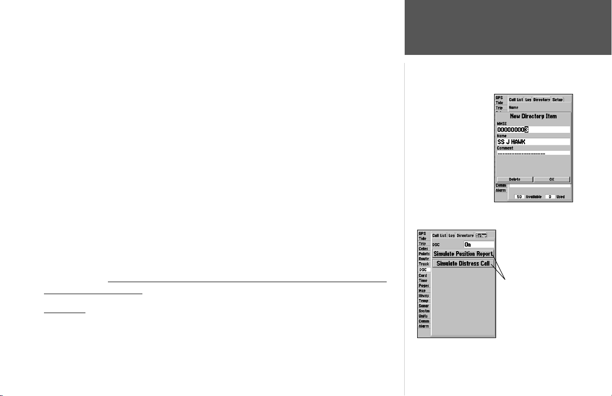
There are two ways to add a new entry into the directory.
To add a new Directory entry:
1. Press Menu, then highlight ‘New Item’ and press ENTER/MARK.
2. Or, with the Directory Tab highlighted press the Arrow Keypad DOWN, highlight an empty fi eld and
press ENTER/MARK to access the New Directory Item window.
The New Directory Item window allows you to input information of a known contact.
To add the MMSI number, Name, or Comment:
1. Press UP/DOWN on the Arrow Keypad to highlight the MMSI, Name, or Comment fi eld.
2. Press ENTER/MARK to highlight the fi rst digit on that fi eld.
3. Press UP/DOWN on the Arrow Keypad to enter the numbers/letters.
4. Press LEFT/RIGHT on the Arrow Keypad to move to the next position.
5. Press ENTER/MARK to accept the entry.
6. Press UP/DOWN on the Arrow Keypad, highlight the ‘Delete’ button and press ENTER/MARK to
delete the entry, or highlight the ‘OK’ button and press ENTER/MARK to accept the entry.
After creating a New Directory Item entry, the name created is attached to that particular MMSI
number. If you return to the Log, the new name is displayed under the corresponding MMSI number.
Another way to input a name is from the Entry Review page or the DSC Distress Call or DSC Position Report pages. The Name fi eld is only available in the GPS. Names cannot be sent like the MMSI
numbers to other DSC users.
DSC Setup
Garmin chartplotters have the ability to turn DSC ‘On’ or ‘Off’. This option is benefi cial for users
who have more than one GPS chartplotter. If you want only DSC to display on a particular chartplotter,
turn DSC off on the remaining Garmin chartplotters that support DSC.
Reference
Main Menu: DSC Tab
Adding a Directory
Entry
DSC Setup
“Simulate..” options only
appear while in Simulator
mode..
81
Page 92
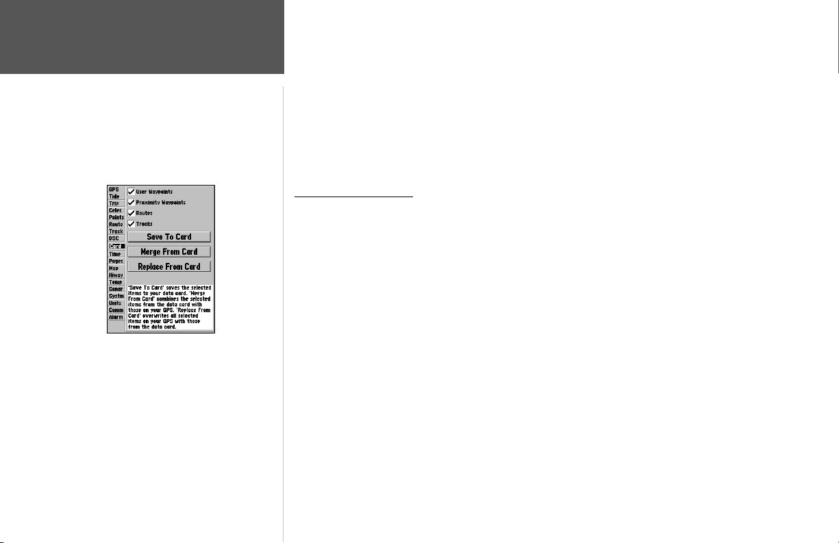
Reference
Main Menu: DSC/Card Tabs
Card Tab
A user also has the ability to simulate a Distress Call or a Position Report on this page. This is helpful for practice before connecting to the real system. The Distress Call simulator also helps to check if
alarms are working properly.
To run a simulation:
1. Place the chartplotter into simulation (see pg. 7).
2. From the Main Menu, select the DSC tab, then highlight the Setup tab.
3. Highlight which simulation you wish to run and press ENTER/MARK.
Using the NAV Button
The receiver of a Distress Call or Position Report can quickly navigate to the caller using the NAV
button. Once the call is logged, press the NAV button and select to Go To the MMSI number or the
Name of the caller.
Card Tab— interface control for saving waypoints, routes and tracks to a data card.When data is saved
to a data card, it may be exchanged with other compatible units and Garmin’s MapSource PC program.
To transfer data to/from a data card:
1. Insert the data card. If there is already user data on the card, highlight ‘User Card’ and press
ENTER/MARK. From the ‘Card’ tab, select the checkbox next to each type of item you want to
transfer. You may also press MENU and choose to ‘Select All’ or ‘Clear All’.
2. Highlight ‘Save To Card’ and press ENTER/MARK to save the selected items to the data card.
3. If transferring data from the card to the unit, highlight ‘Merge From Card’ and press ENTER/MARK
to combine the selected items with those of your GPS. highlight ‘Replace From Card’ and press
ENTER/MARK to overwrite all selected items on your GPS.
4. A ‘Transfer Complete’ message appears once the data has been transfered. Press ENTER/MARK.
82
Page 93
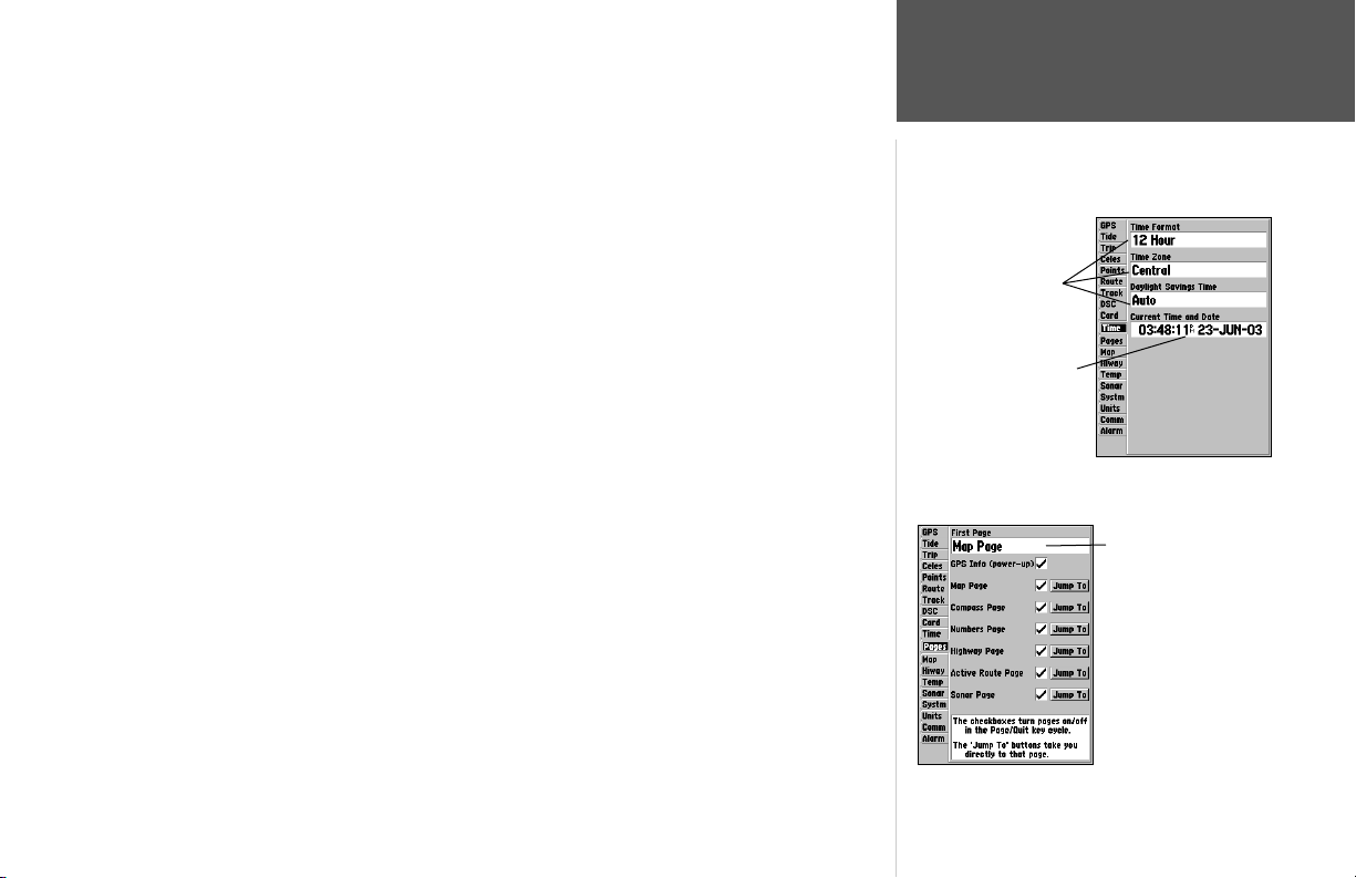
Time Tab— displays the current time and date, allows you to adjust the 12 or 24-hour time format,
enter a time zone, and adjust for daylight savings to show correct local time.
The following options are available:
• Time Format – choose from 12 or 24-hour (military) time format.
• Time Zone – choose your correct time zone to show correct local time or enter a UTC Offset. The
UTC (also called Greenwich Time) offset is how many hours you are ahead or behind the time line.
See the table on page 110 for time offsets.
• Daylight Savings – choose from ‘Auto’, ‘On’, or ‘Off’ to adjust for daylight savings.
Pages Tab— allows you to turn any of the main pages on/off, ‘Jump To’ a particular page, set which
page appears fi rst when you power the unit on, and enable/disable the GPS Info on power up screen.
To select/deselect a main page:
1. Use the ARROW KEYPAD to highlight the box to the left of the page name. Press ENTER to
select/deselect that page. When a page is selected a ‘9’ appears in the box. You must leave at least
one page checked.
You may also press MENU and choose from one of the following and press ENTER:
• All Pages – selects all pages.
• Chart Plotter Only – selects Map page only.
• Navigation Tools Only – selects Compass, Numbers, Highway, and Active Route pages only.
• Basic Fishfi nder – selects Sonar page only.
• Defaults – selects all pages.
To ‘Jump To’ a specifi c page:
1. Use the ARROW KEYPAD to highlight the ‘Jump To’ button to the right of the desired page and
press ENTER.
To set the fi rst page:
1. Use the ARROW KEYPAD to highlight the ‘First page’ option and press ENTER. Highlight the page
you wish to appear fi rst and press ENTER.
Main Menu—Pages Tab
Reference
Main Menu: Time Tab/
Pages Tab
Selectable
Data
Fields
Non-Selectable
Data Field
Main Menu—Time Tab
First Page Option
83
Page 94
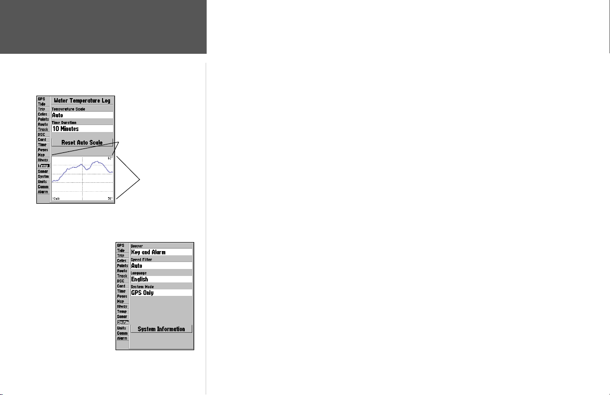
Reference
Main Menu: Temp Tab/
System Tab
Main Menu—Temp Tab
Main Menu—System Tab
(Normal Mode)
84
Time Duration
Temperature Scale
Map Tab— contains setup options for the Map Page. See pages 29-32.
Hiway Tab— contains setup options for the Highway Page. See pages 42-43.
Temp (Temperature) Tab— displays the water temperature log (if equipped with a temperature
transducer/sensor). The chart reads from right to left, so that the most recent temperature measured is
displayed on the far right side of the chart. The dotted lines within the chart indicate intervals in the
temperature scale and the duration of time.
The following settings are available:
• Temperature Scale – sets the temperature range (in degrees) for displaying the log. Select ‘Auto’ to
have the unit automatically determine the best range, or select a span of 2, 4, 6, 8 or 10 degrees.
• Time Duration – sets how fast or slow the temperature log scrolls; the shorter the time duration, the
faster the temperature log scroll. Select a duration from 1 minute to 2.5 hours.
Sonar Tab— contains setup options for the Sonar Page. See pages 38-40.
Systm (System) Tab— controls system settings for beeper, speed fi lter, languages, system mode,
simulator controls, restores factory settings, and displays software version.
The following settings and options are available:
• Beeper – controls audible beep. Select from ‘Off’, ‘Alarms Only’ (sounds for alarms/messages), or
‘Key and Alarm’ (sounds for key presses and alarms/messages).
• Speed Filter – averages speed-readings. Choose from ‘Off’, ‘Auto’ (automatically controls fi ltering),
or ‘On’ (allows you to enter a value from 1 to 255 seconds).
• Language – select from various languages for the unit’s on-screen display.
• System Mode – select from ‘Normal’ (Normal Navigation) or ‘Simulator’ (For practice ONLY),
Sounder Only, or GPS Only.
Set Position* – allows to set your location while in simulator mode. See page 11, starting with
step 2, for additional instructions.
Track Control* – ‘Auto Track’ will steer to the current navigation point. ‘User Track’ allows you to
enter a heading in the ‘Track’ fi eld.
Page 95
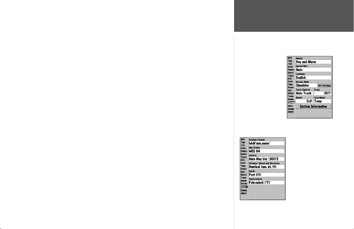
Track* – lets you enter a heading.
Speed* – lets you enter a speed.
Transducer* – lets you simulate using a Depth Only, Temp Only, or Temp/Speed transducer.
* These fi elds will only appear when the unit is in Simulator Mode.
• System Information – displays the unit’s software, basemap version, and electronic serial number.
Press
MENU for the following options:
• Defaults – restores settings on Systm page to default values.
• All Unit Defaults – restores all settings to Garmin’s original setup values for the entire unit.
Units Tab— defi nes settings for Position Format, Map Datum, Heading, Distance, Speed, Elevation,
Depth, and Temperature.
Main Menu—System Tab
(Simulator Mode)
The following settings are available:
• Position Format – is used to change the coordinate system in which a given position reading is displayed. You should only change the position format if you are using a map or chart that specifi es a
different position format or wish to use a format you are familiar with. The default format is latitude
and longitude in degrees, minutes, and thousandths of a minute (hddd°mm.mmm’). The following
additional formats are available:
• hddd.ddddd° – latitude/longitude in decimal degrees only
• hddd°mm’ss.s”
– latitude/longitude in degrees, minutes, seconds
• UTM/UPS – Universal Transverse Mercator / Universal Polar Stereographic grids
• British Grid • Dutch Grid • Finnish KKJ27 • German Grid
• India Zones • Irish Grid • Loran TD • Maidenhead
• MGRS • New Zealand • Qatar Grid • RT90
• Swedish Grid • Swiss Grid • Taiwan Grid • User Grid
• W Malayan RSO
For additional information on Loran TD setup, see pages 102-103.
Reference
Main Menu: System Tab/
Units Tab
Main Menu—Units Tab
85
Page 96
Reference
Main Menu: Units Tab
,
The Units tab settings will affect how navigation information is displayed on the GPSMAP 188/188C/238 Sounder.
When in doubt, seek assistance.
If you are using a map or chart in conjunction with your
GPS, make sure the settings under the ‘Units’ tab of the
GPSMAP 188/188C/238 Sounder match that of the map or
chart. This information should be displayed somewhere on
the map or chart. If the information is not present, contact
the map or chart maker to determine what position format,
datum, heading and units of measure are being used for the
map or chart.
,
WARNING: If ‘User Mag Var’ is selected, you must
periodically update the magnetic variation as your position
changes. Using this setting, the unit will not automatically calculate and update the magnetic variation at your
present position. Failure to update this setting may result in
substantial differences between the information displayed
on your unit and external references, such as a magnetic
compass
86
• Map Datum – allows you to manually select the datum reference used to determine a given position. The default setting is ‘WGS 84’. The unit will automatically choose the best datum depending
upon your chosen position format. Datums are used to describe geographic positions for surveying,
mapping, and navigation and are not actual maps built in the unit. Although over 100 datums are
available (as listed on pages 104-105), you should only change the datum if you are using a map or
chart that specifi es a different datum.
WARNING: Selecting the wrong map datum can result in substantial position errors.
,
When in doubt, use the default WGS 84 datum for best overall performance.
• Heading – lets you select the reference used in calculating heading information. You can select from
‘Auto Mag Var’, ‘True’, ‘Grid’ and ‘User Mag Var’. ‘Auto Mag Var’ provides magnetic north heading
references which are automatically determined from your current position. ‘True’ provides headings
based upon a true north reference. ‘Grid’ provides headings based on a grid north reference (and
is used in conjunction with the grid position formats described on page 73). ‘User Mag Var’ allows
you to specify the magnetic variation at your current position and provides magnetic north heading
references based upon the variation you enter.
To enter a user defi ned magnetic variation:
1. With the Heading fi eld set to ‘User Mag Var’, highlight the heading reference fi eld (immediately to
the right) and press ENTER.
2. Use the ARROW KEYPAD to enter the magnetic variation at your current position and press
ENTER.
• Distance, Speed and Elevation – lets you select the desired units of measure for distance, speed and
elevation readouts in ‘Nautical’ (nm, kt, ft), ‘Statute’ (mi, mh, ft) or ‘Metric’ (km, kh, m) terms.
• Depth – lets you select the desired units of measure for depth in Feet (ft), Fathoms (fa) or Meters (m).
• Temperature – lets you select the desired units of measure for temperature in Fahrenheit (°F) or
Celsius (°C).
Page 97
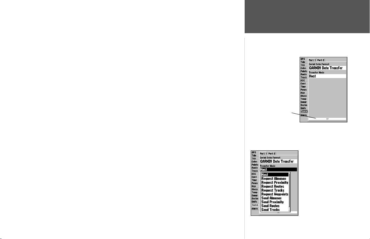
Comm (Communications) Tab— lets you control the input/output format used when connecting
your GPSMAP 188/188C/238 Sounder to external NMEA devices, a DGPS beacon receiver, a personal
computer, another Garmin GPSMAP 188/188C/238 Sounder, etc. If a DGPS receiver is used, WAAS
capability will automatically be turned to ‘Off’. The unit supports two input/output ports. See page 95
for more information on wiring and NMEA information. Individual Port settings are:
Port 1:
• Garmin Data Transfer – the proprietary format used to upload/download MapSource data, exchange
waypoint, route, track, almanac, and proximity data with a PC or another Garmin GPSMAP
188/188C/238 Sounder. When you select ‘Garmin Data Transfer’, there are 11 Transfer Modes to
choose from: Host, Request Almanac, Request Proximity, Request Routes, Request Tracks, Request
Waypoints, Send Almanac, Send Proximity, Send Routes, Send Tracks and Send Waypoints.
• NMEA In/NMEA Out – supports the input/output of standard NMEA 0183 data, and sonar NMEA
input support for the DPT, MTW and VHW sentences.
• None – provides no interfacing capabilities.
Main Menu—Comm Tab
Data Transfer Progress
Port 2:
• Garmin DGPS – used to connect the GPSMAP 188/188C/238 Sounder with a Garmin DGPS beacon
receiver.
• Other DGPS – allows DGPS input using a standard RTCM format, without any output capabilities.
• NMEA In/NMEA Out – supports the input/output of standard NMEA 0183 data, and sonar NMEA
input support for the DPT, MTW and VHW sentences. You may also adjust the NMEA output.
• RTCM In/NMEA Out – allows Differential GPS (DGPS) input using a standard RTCM format and
also provides NMEA 0183 output.
• None – provides no interfacing capabilities.
To select an input/output format:
1. Select the desired Port tab, then highlight the ‘Serial Data Format’ fi eld and press ENTER.
2. Use the ARROW KEYPAD elect the desired setting and press ENTER.
Reference
Main Menu: Comm Tab
When transferring data
between two Garmin units,
be sure to always set one to
‘Host’ and use the other unit
to either Send or Request
the desired data.
87
Page 98
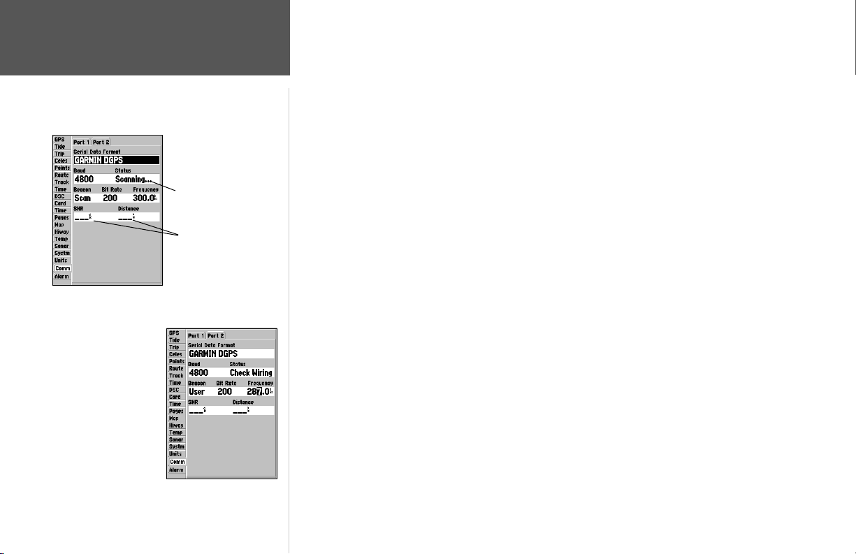
Reference
Main Menu: Comm tab
Status Field
SNR and Distance will
show data when signal
is received.
You may also manually
enter a frequency and
bit rate.
To select a transfer mode:
1. Use the ARROW KEYPAD to select ‘Garmin Data Transfer’ in the ‘Serial Data Format’ fi eld.
2. Highlight the ‘Transfer Mode’ fi eld and press ENTER.
3. Use the ARROW KEYPAD to select the desired setting and press ENTER.
You may also adjust the NMEA output to enable/disable certain sentences and adjust the number
of Lat/Lon output precision digits. You must have one of the ports set to NMEA In/NMEA Out to use
this option. Settings will affect both Port 1 and Port 2 NMEA outputs.
To restore the Serial Data Format settings to the default ‘Garmin Data Transfer’:
1. From the Comm tab, press MENU, highlight ‘Defaults’ and press ENTER.
If ‘Garmin DGPS’ or ‘RTCM In/NMEA Out’ format is selected, additional fi elds are provided to control a Garmin differential beacon receiver directly from your GPSMAP 188/188C/238 Sounder. You may
have the unit automatically scan for the DGPS beacon signal or you can enter the beacon frequency and
bit rate on the unit and the information will be used to tune the beacon receiver.
To have the unit automatically scan for a frequency:
1. With the unit set to ‘
light the “Beacon” fi eld and press ENTER.
2. Highlight ‘Scan’ and press ENTER. The numbers in the ‘Frequency’ fi eld will change as the unit
scans from 284 kHz to 325 kHz, 200 bit rate, then 100, at 6-second intervals.
Garmin
DGPS’ or ‘RTCM In/NMEA Out’, use the ARROW KEYPAD to high-
To restart the scan:
1. Press MENU, highlight ‘Restart Scan’ and press ENTER.
88
Page 99
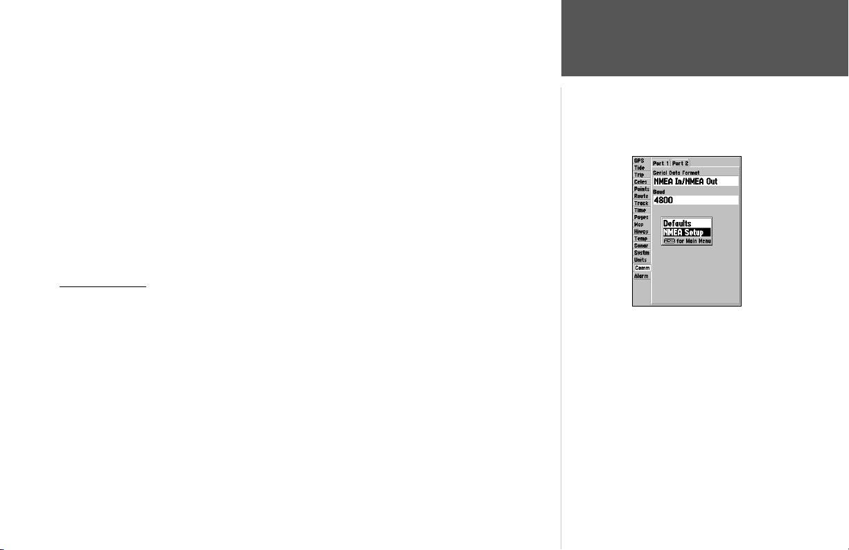
The “Status” fi eld will show one of the following:
• Tuning – unit is attempting to tune to the specifi ed frequency and bit rate.
• Scanning – unit is automatically scanning through the frequencies and bit rates.
• Receiving – unit is receiving DGPS signal and ready for operation.
• Check Wiring – unit is not making connection with DGPS receiver.
Main Menu: Comm Tab
When the unit is receiving a DGPS signal, the “SNR” (Signal to Noise Ratio) and “Distance” fi elds
will show data. The SNR range is 0dB to 30dB, with 30 being the best. The Distance may or may not
show data, depending upon the signal being broadcast from the DGPS site.
The DGPS beacon transmitters are operated by the U.S. Coast Guard (or similar government
agency in other countries), which is responsible for their accuracy and maintenance. For DGPS transmitter problems or to fi nd the most updated list of frequencies and coverage areas, contact your local
USCG, or see their web site at http://www.navcen.uscg.mil/.
NMEA Interface
If you are going to interface the GPSMAP 188/188C/238 Sounder with another piece of equipment
(such as a radio or autopilot), the unit needs to be set to output NMEA data. More information on
wiring and NMEA data may be found on page 95.
To activate the NMEA data:
1. On either port of the Comm Tab, highlight the ‘Serial Data Format’ fi eld and press ENTER.
2. Select ‘NMEA In/NMEA Out’ and press ENTER.
Reference
Activating NMEA data
89
Page 100
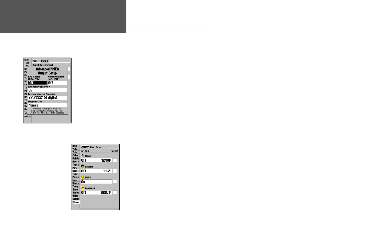
Reference
Main Menu: Comm Tab/
Alarm Tab
Main Menu—Alarm Tab
(System Submenu)
90
Advanced NMEA
Setup Page
Advanced NMEA Output Setup
The GPSMAP 188/188C/238 Sounder NMEA data transmission can be customized to change the
precision of the Lat/Lon minutes, set up the waypoint IDs, and keep the output rate at two seconds. If
the unit is set up to output all of the available NMEA sentences, the output rate may exceed two seconds. The ‘Advanced NMEA Output Setup’ page allows you to turn on/off the GPS status (GSA. GSV),
Waypoint/Route (WPL, RTE), and the Garmin Proprietary sentences. See page 95 for more information
on wiring and NMEA data.
Lat/Lon Minutes Precision allows you to adjust the number of digits to the right of the decimal
point for transmission of NMEA Output, either 2, 3 or 4 digits. The Waypoint ID setting lets you
choose to output the waypoint identifi ers as names or numbers.
To set up the Advanced NMEA page:
1. Highlight ‘NMEA In/NMEA Out’ in the Serial Data Format fi eld, and press MENU. Select ‘NMEA
Setup’ and press ENTER.
2. To change the settings, place the highlight over the desired fi eld and press ENTER. Make a
selection and press ENTER again to accept the selection.
GPSMAP 188/188C/238 Sounder NMEA Sentence Output (NMEA version 2.3 compliant)
Always transmitted: GPRMC, GPGGA, GPGLL, GPBWC, GPVTG, GPXTE, GPRMB
Switchable sentences: GPGSA, GPGSV, GPWPL, GPRTE
Garmin proprietary: PGRME, PGRMZ, PGRMM
Alarm Tab— contains setting for the unit’s alarms. The Alarm tab is divided into three submenus:
System alarms, Nav alarms, and Sonar alarms.
System Tab
Clock – provides an alarm for the system clock. Enter a time in the time fi eld and turn the alarm on
and off from the control fi eld menu. Remember to enter alarm times in the same time format (UTC
or local) you’re using for your system. The unit must be on for the clock alarm to work.
 Loading...