

Garmin 190-00004-00 User Manual
S
M
COMMUNICATION & NAVIGATION
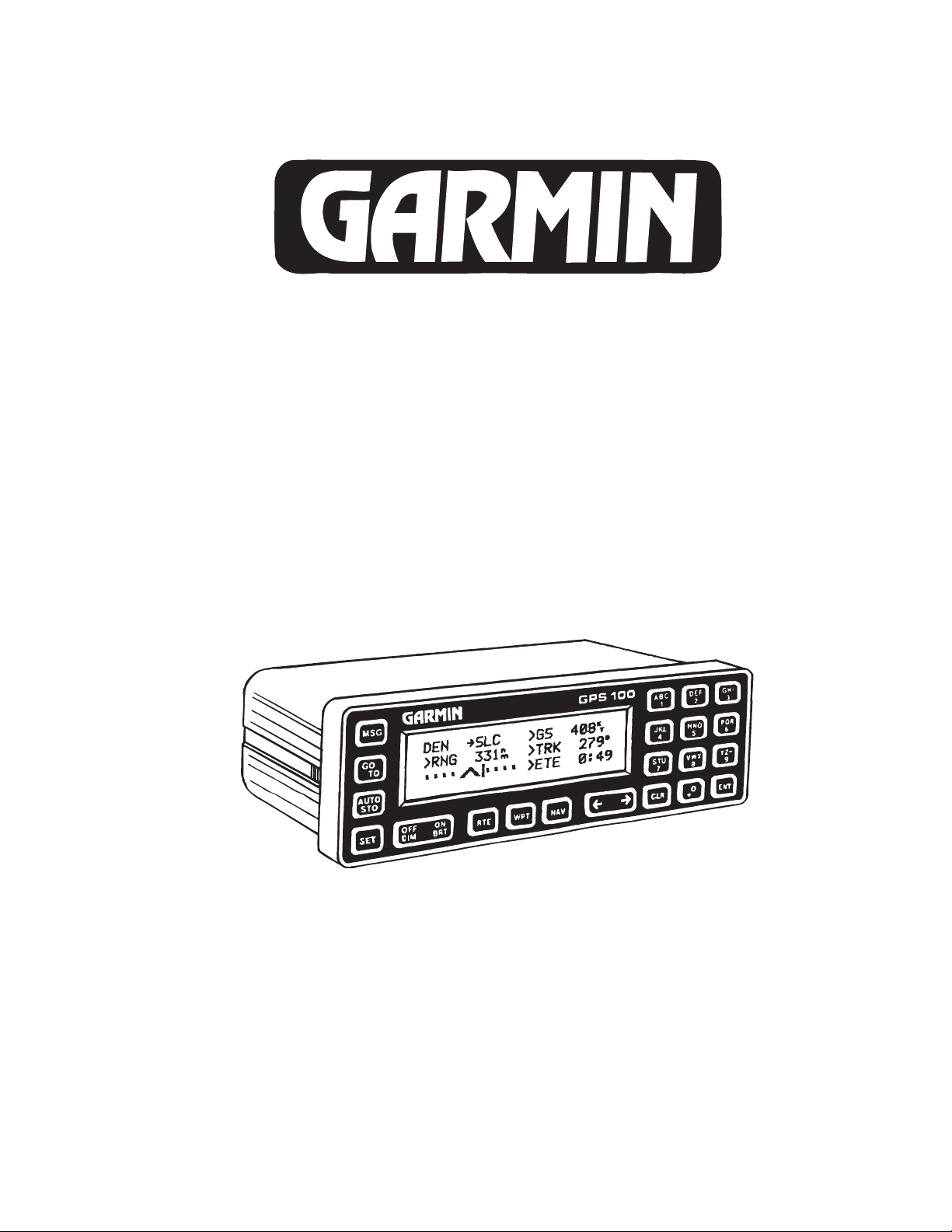
GPS100
AVIATION KIT
INSTALLATION MANUAL
GARMIN INTERNATIONAL, INC. PART NUMBER: 190-00004-00
9875 WIDMER ROAD REVISION G, 15 October 1992
LENEXA, KANSAS 66215
Av. Kit Install. Manual
190-00004-00 Rev. G
Page 1

© Copyright 1992
Garmin International, Inc.
All Rights Reserved
This publication is the proprietary property of Garmin International Inc. It may not
be reproduced or transmitted in any form whether printed or electronic, without the
expressed written consent of Garmin International.
Garmin International, Inc.
9875 Widmer Road
Lenexa, KS 66215
U.S.A.
REVISION RECORD
Initial Rev. 0, 1 Mar 1991 Initial release and STC approval
1224 Rev. 1, 1 May 1991 Minor Change. Added this revision record page.
Changed company name from PRONAV to GARMIN.
1254 Rev. B, 8 Aug 1991 Minor Change. Revised Photos to show GARMIN
company name. Changed Rev sequencing to use
alphabetic rev instead of numeric. Clarify antenna
sealing requirements in 3.2.C
1385 Rev. C, 18 Nov 1991 Minor Change. Replace photographs with drawings
for better reproducibility. Add page numbering. Add
compass safe distance to Fig. 2-2. Revise text.
1506 Rev. D, 26 Feb 1992 Minor Change. Change coax cable type.
1549 Rev. E, 30 Mar 1992 Add Low Profile Antenna and Appendix A.
1608 Rev. F, 4 May 1992 Minor Change. Revise installation details in Appendix
A.
1839 Rev. G, 15 May 1992 Change company address and add eco #'s to record
page.
Av. Kit Install. Manual
190-00004-00 Rev. G
Page 2

GPS 100 AVIATION KIT INSTALLATION MANUAL
TABLE OF CONTENTS
SECTION 1 GENERAL DESCRIPTION
1.1 INTRODUCTION
1.2 TECHNICAL CHARACTERISTICS
1.2.1 PHYSICAL CHARACTERISTICS
1.2.2 OPERATIONAL CHARACTERISTICS
1.2.3 INTERFACES
SECTION 2 INSTALLATION CONSIDERATIONS
2.1 ANTENNA CONSIDERATIONS
2.1.1 SATELLITE VISIBILITY
2.1.2 NOISE SOURCES
2.1.3 ELECTRICAL BONDING
2.1.4 ANTENNA LIMITATIONS
2.2 RACK CONSIDERATIONS
2.2.1 ACCESSIBILITY
2.3 CABLING AND WIRING
2.4 ANNUNCIATORS
SECTION 3 INSTALLATION PROCEDURE
3.1 INSTALLATION KIT CONTENTS
3.2 ANTENNA INSTALLATION
3.3 CABLE INSTALLATION
3.4 RACK INSTALLATION
3.5 AVIATION INTERFACE SET-UP
3.6 GPS 100 INSTALLATION
3.7 PLACARD
SECTION 4 CHECKOUT PROCEDURE
APPENDIX A INSTALLATION DETAILS FOR BEECH B60
Av. Kit Install. Manual
190-00004-00 Rev. G
Page 3

LIST OF ILLUSTRATIONS
FIGURE
1-1 AVIATION RACK PINOUT DEFINITION
1-2 INTERCONNECT SCHEMATIC
2-1 ANTENNA INSTALLATION CONSIDERATIONS
2-2 GPS INSTALLATION CONSIDERATIONS
3-1 BLADE ANTENNA INSTALLATION
3-1A LOW PROFILE ANTENNA INSTALLATION
3-2 COAX CABLE INSTALLATION FIGURE
3-3 AVIATION RACK DIMENSIONS
3-4 AVIATION RACK INSTALLATION
A-1 BLOCK DIAGRAM
A-2 FUSELAGE STATIONS
A-3 PANEL LAYOUT
A-4 WIRING DIAGRAM
A-5 BREAKER LOCATIONS
Av. Kit Install. Manual
190-00004-00 Rev. G
Page 4

SECTION 1 GENERAL DESCRIPTION
1.1 INTRODUCTION
This manual describes the physical, mechanical, and electrical characteristics and
the installation requirements for the GPS 100 Aviation Kit.
After installation of the GPS 100 system, FAA Form 337 must be completed by an
appropriately certificated agency to return the aircraft to service.
NOTE: The GPS 100 must have software version 2.09 or later to interface properly with
the aviation rack. If the GPS 100 being installed has an earlier software version,
contact your nearest GARMIN service center to obtain a software update.
1.2 TECHNICAL CHARACTERISTICS
The GPS 100 offers the versatility of fixed installation in a panel mounted aviation rack
as well as complete portability.
1.2.1 Physical Characteristics
Width: 6.25 Inches
Height: 2 inches
Depth: 3.95 inches
GPS 100 Weight: 28 oz.
Blade Antenna Weight: 8 oz.
Low Profile Antenna Weight: 4 oz.
Aviation Rack Weight: 11 oz.
Max Air Speed: Subsonic
(Structural rating for antenna)
1.2.2 Operational Characteristics
Temperature Range: -15 oC to +70 oC
Humidity: 95% non-condensing
Altitude Range: -1,500 to 50,000 ft.
Power Input: 11 to 33 VDC at 500mA MAX
Av. Kit Install. Manual
190-00004-00 Rev. G
Page 5

1.2.3 Interfaces
The aviation rack contains an electronic module which provides interfaces to various
general aviation instruments. Figure 1-1 defines the function of each pin on the 15
pin DSUB connector located at the back of the rack. Figure 1-2 depicts the
interconnects between the rack and other instruments. The following interfaces are
provided.
CDI: Capable of driving up to three 1000 ohm parallel
(Pins 1 and 4) loads, +150 millivolts full scale deflection with a
maximum output of +300 millivolts.
To/From: Capable of driving up to three 200 ohm parallel
(Pins 2 and 5) loads, +82 millivolts full scale deflection.
Nav Flag: Capable of driving up to three 1000 ohm parallel
(Pins 3 and 6) loads, 375 millivolts for flag out-of-view, and
+40 millivolts for flag in-view.
OBI data: Output providing bearing to waypoint data for a
(Pins 7, 8, and 12) Bendix/King RMI (KI 229 or equivalent).
Message annunciators: Output capable of driving negative or positive logic
(Pins 9 and 11): annunciators.
Message audio: Output capable of producing 10 milliwatts into 500
(Pin 10) ohms at a frequency of 2 KHz.
RS232 data: Output capable of driving ARGUS3000/5000/7000
(Pin 13) and STORMSCOPE SERIES II with NAVAID moving
map displays and Shadin fuel management system.
Conforms to the EIA specification RS-232C.
SECTION 2 INSTALLATION CONSIDERATIONS
Careful planning and consideration of the suggestions in this section are required to
achieve the desired performance and reliability from the GPS 100.
2.1 ANTENNA CONSIDERATIONS
2.1.1 SATELLITE VISIBILITY
The GPS 100 Blade or Low Profile Antenna must be mounted on top of the aircraft in
the upright position. For best performance select a location with an unobstructed
view of the sky above the aircraft when in level flight. Figure 2-1 illustrates a typical
blade antenna installation. Recommended installation locations for the Low Profile
Antenna are the same.
Av. Kit Install. Manual
190-00004-00 Rev. G
Page 6

2.1.2 NOISE SOURCES
The antenna should be located at least 3 ft from transmitting antennas such as VHF
Comm, HF transmitter, DME, Transponder, and Radar. Cabling for the GPS 100
should not be routed near components or cabling which are sources of electrical noise.
2.1.3 ELECTRICAL BONDING
No special precautions need to be taken to provide a bonding path between the
antenna and the aircraft structure.
2.1.4 ANTENNA LIMITATIONS
The GPS 100 Blade and Low Profile Antennas are recommended for installations
where the airspeed of the aircraft will be subsonic. For aerodynamic considerations,
the Low Profile Antenna is recommended for operation above 200 kts.
2.2 RACK CONSIDERATIONS
2.2.1 ACCESSIBILITY
Plan a location which gives the pilot complete and comfortable access to the entire
keypad and which is plainly visible from the pilots perspective. Check that there is
adequate depth for the rack in the instrument panel. A location away from heating
vents or other sources of heat generation is optimal. Figure 2-2 illustrates a typical
aviation rack installation.
2.3 CABLING AND WIRING
Use only the antenna cable supplied in the installation kit. Other cabling may lead
to degraded performance. Check that there is ample space for the cabling and mating
connectors. Avoid sharp bends in cabling and routing near aircraft control cables.
2.4 ANNUNCIATORS
If the installation includes any electrical interface with other flight instruments, an
annunciator may be required. Refer to current FAA directives.
Av. Kit Install. Manual
190-00004-00 Rev. G
Page 7

SECTION 3 INSTALLATION PROCEDURE
3.1 INSTALLATION KIT CONTENTS
One of the following two installation kits is required for aircraft installation, depending
on the type of antenna used.
The GPS 100 Aviation Installation Kit (010-10002-00) consists of the following parts:
P/N DESCRIPTION QTY
011-00013-00 BLADE ANTENNA SUBASSEMBLY 1
011-00014-00 RACK SUBASSEMBLY 1
115-00015-00 BACKING PLATE 1
117-00001-00 EJECTOR PIN 4
161-00024-00 PLACARD, INSTRUMENT PANEL 1
190-00004-00 INSTALLATION MANUAL (THIS MANUAL) 1
211-20001-00 #8-32 SS, PH, FLAT HEAD SCREW 4
253-00002-00 ANTENNA GASKET 1
320-00003-00 CABLE ASSY, COAX 1
330-00017-00 CONNECTOR, BNC, MALE, CLAMP 1
330-00024-00 CONNECTOR, 15 PIN DSUB, FEMALE 1
The GPS 100 Low Profile Aviation Installation Kit (010-10008-00) consists of the
following parts:
P/N DESCRIPTION QTY
011-00042-00 LOW PROFILE ANTENNA SUBASSEMBLY 1
011-00014-00 RACK SUBASSEMBLY 1
115-00031-00 BACKING PLATE 1
117-00001-00 EJECTOR PIN 4
161-00024-00 PLACARD, INSTRUMENT PANEL 1
190-00004-00 INSTALLATION MANUAL (THIS MANUAL) 1
210-10004-09 NUT, SELF-LOCKING, #8-32 4
253-00002-00 ANTENNA GASKET 1
320-00003-00 CABLE ASSY, COAX 1
330-00017-00 CONNECTOR, BNC, MALE, CLAMP 1
330-00024-00 CONNECTOR, 15 PIN DSUB, FEMALE 1
The following equipment is required for installation but is not included in the
installation kit:
#6-32 Flat Head Screw (4 ea.) #6-32 Self-locking Nut (4 ea.)
Av. Kit Install. Manual
190-00004-00 Rev. G
Page 8

3.2 ANTENNA INSTALLATION
The Blade Antenna outline and footprint dimensions are shown in Figure 3-1. The Low
Profile Antenna outline and footprint dimensions are shown in Figure 3-1A. Both
antennas require the same Installation procedure.
A. Using the backing plate as a template, mark the location of the mounting holes and
the through hole for coax cable. Drill or punch the holes.
B. The antenna installation must provide adequate support for the antenna considering a maximum drag load of 14 lbs (at subsonic speed). Install a doubler plate to
reinforce thin skinned aircraft. Observe guidelines for acceptable installation
practices as outlined in AC 43.13-2A.
C. Seal the antenna and gasket to the fuselage using a good quality electrical grade
sealant. Use caution to insure that the antenna connector is not contaminated with
sealant. Insure that the mounting screws are fully tightened and that the antenna
base is well seated against the gasket. CAUTION: Do not use construction grade RTV
sealant or sealants containing acetic acid. These sealants may damage the electrical
connections to the antenna. Use of these type sealants may void the antenna
warranty.
3.3 CABLE INSTALLATION
A. Route the coax cable supplied to the rack location keeping in mind the recommendations of Section 2. Secure the cable in accordance with good aviation practice.
B. Trim the supplied RG-59/U cable to the desired length and install the BNC
connector (330-00017-00) per the cabling instructions on Figure 3-2.
3.4 RACK INSTALLATION
A. Figure 3-3 shows outline dimensions for the aviation rack. Install the rack in a
rectangular 6.320" x 2.000" hole in the instrument panel. Exercise caution when
installing the rack into the instrument panel. The rack is designed to facilitate removal
of the GPS 100 for portable use. Deformation of the rack may make it difficult to install
and remove the GPS 100.
B. Install the rack in the aircraft panel using four #6-32 countersunk screws and
four self-locking nuts. The screws are inserted from the inside through the holes
in the sides of the rack (see Figure 3-4).
Av. Kit Install. Manual
190-00004-00 Rev. G
Page 9
 Loading...