

Page 1

Owner’s
Manual 8c
Reference
#GflRNIN.
Page 2

Software Version 2.03 or above
© 1996 CARMIN Corporation
1200 E. 151st Street, Olathe, KS USA 66062
CARMÍN (Europe) LTD
Unit 5, The Quadrangle, Abbey Park Industrial Estate, Romsey, U.K. 5051 9AQ
All rights reserved. No part of this manual may be reproduced or transmitted in
any form or by any means, electronic or manual, including photocopying and record
ing, for any purpose without the expressed written permission of CARMIN.
Information in this document is subject to change without notice. CARMIN
reserves the right to change or improve its products and to make changes in the con
tent without obligation to notify any person or organization of such changes or
improvements.
CARMÍN, AutoLocate, AutoStore, AutoZoom, CPSCOM, PhaseTracl2, and
TracBack are all trademarks of CARMIN Corporation and may not be used without its
expressed permission.
November 1996 Part #190-00110-00 Rev, B Printed in USA,
Page 3

IMPORTANT!
The Telecommunications Act of 1996, effective February 8, 1996, provides
the FCC discretion to eliminate radio station license requirements for aircraft
and ships. At the present time, you do not need an individual license to operate
the GPS COM 190 aboard your private aircraft in many circumstances. To find
out the specilic details on whether you are exempt from licensing, please see
FCC Fact Sheet PR 6000 or contact the FCC at 1-800-322M117.
Note that no license is required for a portable radio used only as a backup on
an aircraft which already has a station license per FCC 404 Instructions dated
1994.
If an aircraft license is required or desired, contact the FCC at
1-800-322-1117 to request FORM 404, Application for Aircraft Radio Station
License
If the GPS COM 190 transmitter will be used as a ground station (from the
ground outside of an aircraft), contact the FCC at 1-800-322-1117 to request
FCC Form 406, Application for Ground Radio Station Authorization in the
Aviation Services.
The FCC also has a fax-on-demand service to provide forms by fax at
1-202-418-0177.
The GPSCOM 190 owner accepts all responsibility tor obtaining the proper
licensing before using the transmitter.
Page 4

INTRODUCTION
Piidiing lisi
GPSC0M190
OWNER’S MANUAL
Betöre getting started, check to see that your GARMIN GPSCOM 190
package includes the following items. If you are missing any parts, please
contact your dealer immediately.
GPSCOM 190 Unit
Flex Whip Com Antenna
Quick Reference Card
Owner’s Manual
External GPS Antenna Kit
Universal Yoke Mount
Headset/Microphone Adapter
Trickle Charger/AC Adapter
Cigarette Lighter Adapter
Belt Clip
Carrying Case
Wrist Strap
Page 5

NTRODUCTION
CmUioiw
aiTiON
The GPS system is operated by the government of the United States, which
IS solely responsible for its accuracy and maintenance. The system is subject
to changes which could affect the accuracy and performance of all GPS
equipment. Although the GPSCOM 190 is a precision electronic NAVigation
AID (NAVAID), any NAVAID can be misused or misinterpreted and there
fore, become unsafe.
Use the GPSCOM 190 at your own risk. To reduce the risk of unsafe
operation, carefully review and understand all aspects of this Owner’s
Manual and thoroughly practice operation using the simulator mode prior
to actual use. When in actual use, carefully compare indications from the
GPSCOM 190 to all available navigation sources including the information
from other NAVAIDs, visual sightings, charts, etc. For safety, always resolve
any discrepancies before continuing navigation,
NOTE: This device meets requirements for Part 13 of the FCC limits for
Class B digital devices lor home or office use. It has been tested for compli
ance with all necessary FCC standards. This equipment generates, uses, and
can radiate radio frequency energy and, if not installed and used in accor
dance with the instructions, may cause harmful interference to radio com
munications. However, there is no guarantee that interference will not occur
in a particular installation. If this equipment does cause harmful interference
to other equipment, which can be determined by turning the equipment off
and on, the user is encouraged to try and correct the interference by relo
cating the equipment or connecting the equipment to a different circuit than
the affected equipment. Consult an authorized dealer or other qualified ser
vice technician for additional help if these remedies do not correct the prob
lem. Operation is subject to the following conditions: (1) This device cannot
cause harmful interference, and (2) this device must accept any interference
received, including interference that may cause undesired operation. The
GPSCOM 190 does not contain any user-serviceable parts. Repairs should
only be made by an authorized service center. Unauthorized repairs or mod
ifications could void your warranty and your authority to operate this device
under Part 15 regulations.
Page 6

NTRODUCTION
Table Of
Contents
SECTION ONE Getting Started
Unit Description/Keys and Controls ......................................................2-5
Initializing the Receiver/Acqmring Satellites.........................................6-7
SECTION TWO GPSCOM 190 Takeoff Tour
GPS Page Sequence/Frequency Entry
Simulator Mode/Activatmg a GOTO .................................................11-12
Basic Page Operation .........................................................................13-19
Emergency Channel Selection/Auto Zoom .............................................20
Cancel GOTO/Power Off
SECTION THREE Refemice
Waypoint Categories/Nearest Pages...................................................23-32
Communication Pages and Functions ................................................33-42
GOTO/TracBack Navigation .............................................................43-46
Routes.................................................................................................47-51
Satellite Status Page ...........................................................................52-53
Position Page/Map Page Functions ....................................................54-60
Navigation Page/Main Menu..............................................................61-68
Interlace Setup and Features...............................................................69-70
Setup Menu Options ..........................................................................71-81
Appendix A—Accessories Cr Installation .........................................82-89
Appendix B—Specifications
Appendix C—Messages .....................................................................92-93
Appendix D—Map Datums ...............................................................94-95
Appendix E”Time Offsets .......................................................................96
Appendix F—Index ............................................................................97-99
..................................................................
.................................................
.............................................................
9-10
21-22
90-91
Page 7

GETTING
STARTED
BNC Antenna
Connector
Fiex Com
Antenna
Alphanumeric
Keypad
Squelch
Control
GH) GH) G3 CM?
GS CH?
f*” Ì
Volume
Control
The GPSCOM 190 combines a 12 paral
lel channel GPS receiver with a 760-channel
digital VHP aviation communications trans
ceiver in a convenient handheld package.
Direct data entry and functional control is
provided by the alphanumeric and function
keys located on the front of the unit
(alphanumeric keys are labeled with white
numbers and letters, function keys are
labeled green). The squelch and power/volume controls are located on the top of the
the unit. The microphone is located in the
lower left speaker area.
Internal GPS
Antenna
Function
Keys
Speaker
Microphone
Arrow Keypad
LCD Display
Front View
Page 8

GETTING
STARTED
The backlight, frequency transfer, and push-to-talk buttons, along with the charger/AC
adapter connector are located on the left side of the unit. The connectors for the external GPS
antenna and power/data cable are located on the right side. The removable Ni-Cad battery
pack is attached to the back of the unit. See Appendix A for instructions on battery pack
removal.
Page 9

GETTING
STARTED
Ke>s and
Controls
t
0
Use the two-speed arrow keypad to enter data. Press on a particular
arrow key once to scroll through data options slowly. Press and hold down
an arrow key for faster scrolling.
Use the UP and DOWN arrow keys to select alphanumerical characters
and menu choices, and to move the field highlight from field to field.
Use the LEFT and RIGHT arrow keys to move the selected character
field, and to move the highlight from field to field. The left arrow key is
also used to clear a selected field.
The ALPHANUMERIC keys enter characters into a highlighted field with
out needing to press ENTER to access data entry
The GOTO/NRST key quickly sets a direct course to a selected destina
tion. Pressing GOTO twice displays the nearest waypoint page.
The WPT key accesses the GPSCOM 190’s internal database of airports,
VORs and other waypoints, as well as the AutoStore function.
Pressing the OWX key enters a zero into a numeric or alphanumeric field.
It also places a weather channel into a highlighted standby frequency field.
The GPSCOM key lets you choose between the main GPS and main
communication pages. Press and hold the GPSCOM key to select the
121.5
MHz. emergency frequency as the active frequency.
Page 10

GETTING
STARTED
K^'s and
Controls
The PAGE key scrolls through the main data pages in sequence and
returns the display from a submenu page to a main page. It also displays
the message screen when a message alert appears.
The ENTER key confirms data entry and on-screen responses. This key
also activates highlighted fields to allow data entry.
The QUIT key returns you to a previous page, or clears data entry and
restores a data field’s previous value.
The FREQUENCY TRANSFER button flip-flops the active and stand
by frequencies.
The SQUELCH control eliminates receiver background noise and
allows only received transmissions to be heard.
The PUSH-TO-TALK (PTT) switch activates the GP5COM 190 trans
mitter on the active frequency.
The BACKLIGHT button illuminates the alphanumeric keys, arrow
keypad, and LCD Screen through four levels of backlighting (three lev
els of brightness and oil).
The ON/OFFA^OLUME control turns the unit on and off and adjusts
the volume level.
Page 11

Getting
Started
Ittííiflíí^ÍHg The
Receher
Importantl
Make
sure
you charge the
Ni-Cad battery pack for
flours
before
GPSCOM 190 to ensure
optimum capacity and per
formance. Note:
cfiuiging the
turn
the unit
fuH charge. Complete
instructions on charging
pack are
given on
14
using ^lour
Wfien
battery pack,
off to
ensure
the
page 89.
c
Welcome to the
GPSCOM
19B
fOFTUARE UEFt E.D4
COPYRIGHT 1995-9E
ORRHIH CORP
Welcome Ptrge
Initializing the GPSCOM 190 for First-Time Use
The first time you power up your new GPSCOM 190
is an important step in getting the best possible GPS perlormance
collect satellite almanac data and
position. This initialization process takes approximately
The receiver
must
he given an
oppoTtunify
cstolilish ií5 present
to
3 to 5 minutes and is only necessary for first time opera
tion, after memory loss, or when the receiver has been
moved more than 500 miles from the last calculated posi
tion with the power off. Once your GPSCOM 190 has
been properly initialized, you should acquire satellites
and obtain a position quickly each time you power up.
Your GPSCOM 190 is shipped in the AutoLocate
mode, which is designed to let the receiver “find itself
without using its last known position (you don’t need to
worry about what lai/lon is currently displayed on the
a
position page, as the unit is not using that information to
calculate your present position.)
To power up your unit for first time use:
1. Position the internal GPS antenna so it has the best pos
sible view of the sky (the internal patch antenna is locat
ed just above the keypad, marked by the embossed
globe.) if necessary, see Appendix A for instructions on
the installation of the GA 27 external GPS antenna.
2. Turn the unit on by rotating the volume control
clockwise.
3. Rotate the squelch control clockwise until receiver
noise disappears.
4. Remain in the same location until the GPSCOM 190 has
calculated a position (the status page will be replaced
by the position page if no other buttons have been
pressed during acquisition).
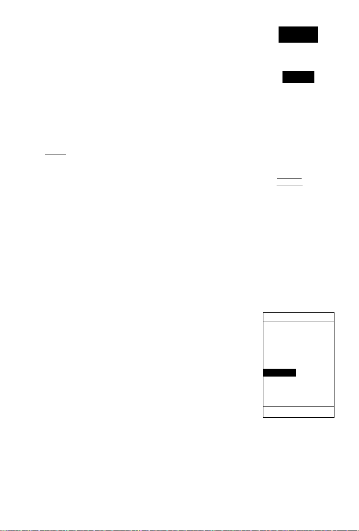
Welcome Page and Database Configuration
The welcome page will be displayed while the unit
conducts a self test. Once testing is complete, the wel
come page will be replaced by the database page (see the
top of page 7), showing the database issue date. Updates
to the database are available from GARMIN or Jeppesen
on a subscription or one time basis.
Page 12
%
ftriERICHS SUH
CYCLE
9607
EFFECTIUE
20 JUH 96
TO
IS JUL 96
Getting
Started
EZinit
HCCUIRIHG
EZinit
After a few seconds, the status page will appear with
the EZinit
prompt
ready for you to select one of two ini
CHOOSE INIT
METHOD:
1 SELECT
tialization methods:
• Select Country— allows you to initialize the receiv
er by selecting your present position from a list of
2 RUTOLOCRTE
G HO RE-INIT
countries in the GPSCOM 190’s internal database.
This feature provides a position fix in 3-5 minutes.
• AutoLocate— allows the GPSCOM 190 to initialize
itself and calculate a position fix without knowing
your present position. This feature provides a posi
tion fix in approximately 5 minutes.
If the EZinit prompt has not automatically appeared
on the status page, press
If you’ve already initialized the GPSCOM 190 and the
EZinit prompt appears, highlight the 'NO RE-INIT’ selec
tion with the arrow keypad and press The EZinit
prompt may appear if you’ve had the unit on in normal
mode while indoors, or li the antenna is shaded while
acquiring satellites.
To initialize the receiver:
1. Use the up or down arrow keys to highlight the
'COUNTRY' option and press
2. Use the down key to scroll through the country listings
until the country where you are presently located
appears.
3. Use the up or down arrow key to highlight the
country/state/region you're in. If the country you're in is
not listed, select another country within 500 miles of
your present position.
4. Press
to finish.
WX05 12^.90
The EZinit prompt will
outomatiMib' appeor
receiver
ized.
appear during normal
the antenna
unit is indoors.
1 COUNTRY LIST 1
USfl"flZ
USfl-Cfl
USfl-CO
USfi-CT
USfl-DE
USfi-FL
USfl-Gfl
USfl-HI
USfl-Ifl
IWX05 12^1.901
Ij necessary,
keypad to
country and
of
^Dur present position
from the
ENTER. 1/ the counti^ is
not listed, select the closest
country,
instead.
___
taamnsn
FROM LIST
(CONTINUE
ftCOUIRINOJ
if the
needs to be
The prompt may aho
initial
is shaded
use
or the
1
use the arrow
highlight the
region or
state
list
and press
region or
state
FT
f
Page 13
Getting
Started
Acquirittg
Satellites
ilH
B4TSEF
121.50 130.75
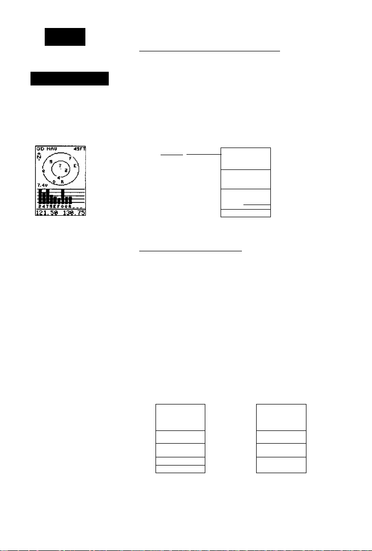
Once satellites have been
found,
strengih
played
colit'cted.
strength bars
help determine if
are
061ft
hollow signal
bars
will
be dis
whik
data
is being
The
signal
can he used to
satellites
being shatfeA
_
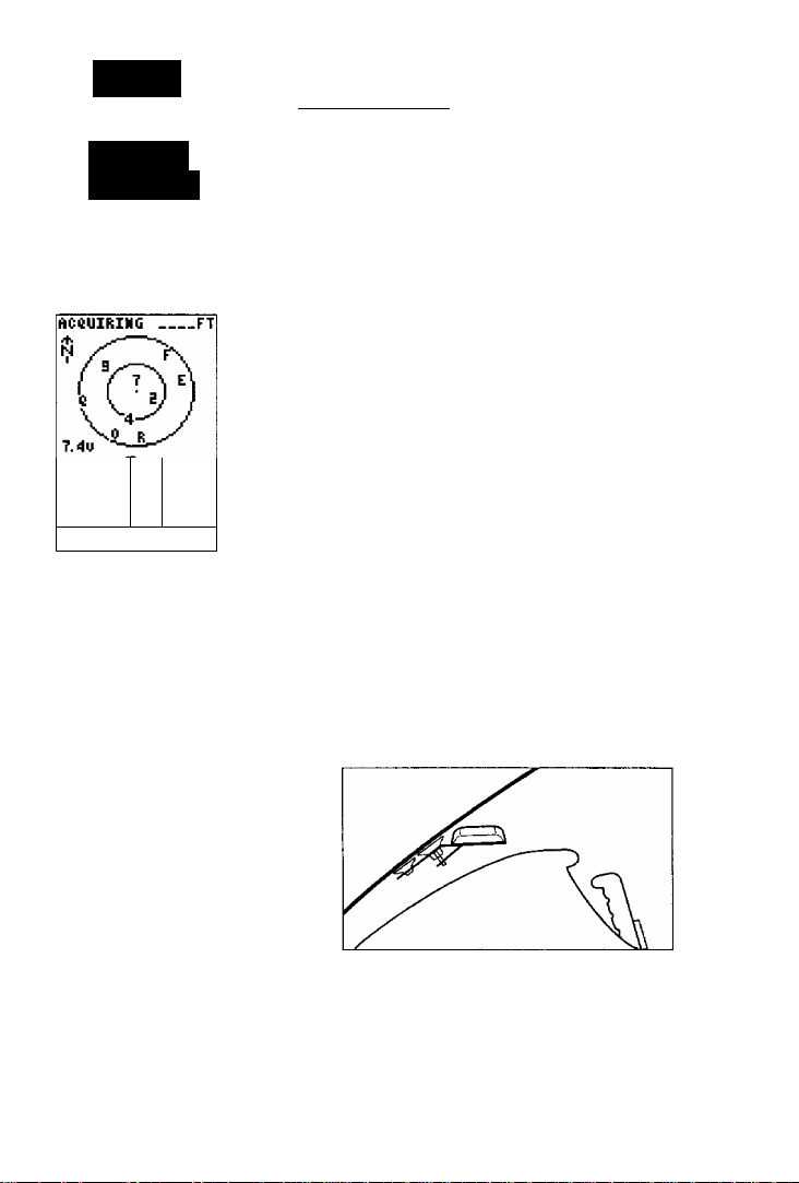
Acquiring Satellites
The GPS COM 190 will now begin searching for the
appropriate satellites for your position and should
acquire a fix within three to five minutes. Verify getting a
position lix by watching the status page transition to the
position page (provided you haven’t pressed any other
keys) or by looking for a ‘2D NAV or ‘3D NAV’ status at
the top-left corner of the status page.
If you have trouble initializing the receiver or getting
a position fix, check the following:
• Does the antenna have a clear view of the sky?
U there are large buildings such as hangers, metal sur
faces, or other obstructions, the unit may not be
receiving enough satellite signals to calculate a fix.
• Is the right country/state selected from the EZinit
list?
Check for the correct approximate lat/lon on the
position page or reselect the appropriate country
from the list to restart the initialization.
• Have you moved more than 500 miles from the
last calculated position with the receiver oH?
Reinitialize the receiver, selecting the country/state of
your new location from the EZinit list.
Remote Antenna Installation
If your installation does not provide an adequate view
ol the sky, install the remote antenna included with your
unit. See page 86 for installation instructions.
Page 14

GPSCOM 190 Takeoff Tour
The takeoff tour is designed to quickly guide you
through basic features and functions of the GPSCOM 190
using a simulated trip.
POH’£T Ofl
Once you’ve completed the tour and become familiar
with the mam pages and features of the unit, refer to the
reterence section for complete instructions on installation
and performing specific tasks and functions.
The takeoff tour assumes you have initialized the unit
and have not changed any of the default settings. If you
have changed any settings, the descriptions and pictures
used may not match your configuration. You’re now
ready to power up and take off
To turn the unit on;
1. Rotate the power/volume knob clockwise,
2. Turn the squelch knob counterclockwise until the
receiver background noise disappears.
The takeojf tour assumes
>'ou
are
database. Jj
an Atlantic International
database, try
jligkfrom EGLC to EGSR.
For a Pacific International
database,
to PHNG.
3. After the unit performs a self-test, the database informa
tion page will appear, listing the date of the aviation
database.
Takeoff
Tour
hnportanti
using an Americas
_you
are
using
simulating
try flying
PHDfi
a
%
CVCLE
9607
EFFECTIUE
20 JUH 96
TO
19 JUL 96
The database page reflects the worldwide database of
airports and VORs contained in the GPSCOM 190.
Database updates and subscriptions are available from
GARMIN and Jeppesen. After a few seconds, the database
information page will be replaced with the satellite status
page. The status page provides a visual reference of satel
lite acquisition and status, with signal strength bars and a
satellite sky view in the center of the screen.
Use the status page to
instantl)' view satellite
usage and
strength.
current
signal
Page 15
Takeoff
TOUR
Page Sequence
Scrolling Throujgh the Main GPS Pages
The GPSCOM 190 features five main GPS pages in a
continuous loop; satellite status, position, map, naviga
tion, and main menu. Try scrolling through the pages by
pressing You can also scroll in the opposite direc
tion (or return to a previous page) by pressing
Status Page Position Page
I [ 111111111111111111
P3D 345 H DIS n
TRACK
356^
TRIP
000. e;
SPEED
0.0^
ALT
2500^T
N 39^00.000* W095^00.000'
1419:18
126.77 12^. 9a
Tnfering
a com frequency
from
the position
page.
Map
Page Navigation Page
tracksTeed
325-" 150"t
TRIP
ALT
002.5E
2'178''r
H 29*53.283'
W097*-41.7^2'
12^27:15
130.75 119.00
Frequency Entry - GPS Pages
190, there may be times when you’ll want to quickly
enter a frequency from a GPS page. The GPSCOM 190
will always display the active and standby frequencies at
the bottom of every GPS page. The standby frequency is
displayed on the right side of the page and the active fre
quency on the left.
To enter a frequency from any GPS page:
Menu Page
BRG
H>N I crC
an
Amv
KHVI
i sjft
,L T31
126.77 119.1
DST
325* 31.0S.
325*
150’V
TRK
SFD
3R3
1 iS .
HTK
ETE
12:24 0,00^
12:27
TIME MMAU
130.75119.00
During the course of navigating with the GPSCOM
1. Use the arrow keys or press highlight the
standby frequency field.
[aan 345^N 015 tj
TRACK SPEED
356* 0.0'V 356* 0.0-T
TRIP ALT TRIP ALT
000.0R. 2500^
H 39*00.000'
W 095*00. 000' U>095*00. 000'
12:40:34 12:40:59
136.97 119.00
[laa 345 "h Pip ij
TRACK SPEED
000.01^ 2500^
N 39*00.000'
136 97 HE15EI
HAIH MENU
fllarms/CDI
E$-B Menu
User Wtsl List
Routes
Messages
130.75 119.1
Page 16

The starting position of our simulated flight is
Lockhart Municipal Airport (50R, the ICAO identifier), in
Lockhart, Texas. Before we begin, let’s practice alphanu
meric data entr}'^ by entering the tow'er frequency lor
Lockhart Municipal, which is 124,90 MHz.
1. Press the button labeled
2. Press I
3. Press I
4. Press I
5. Press I
6. Press ^0 to confirm.
If an incorrect number is selected during entry:
1. Use the arrow keys to move away from the incorrect
character and then back to it,
2. Enter the correct character.
3. Press to confirm.
To place the standby frequency in the active frequency
Beld;
1, Press the frequency transfer button on the side of the
receiver.
To transmit on the active frequency:
1. Press the PIT switch.
Frequency
E11Í13
111 ■ 11111111111111
33D 2AS N ai5 E
11 ■ I ■ ■ I ■ ■ ^1 ■ ■ ■ ■ 1111
TRACK
356^
TRIP ALT
eee.eiï. 25ee^r
N 39*00.000’
U 095*00.000'
126.77 12^.90
Entering the tower frequen
cy for the starting
of the
124.90 MHz
OPERATION MODE
Current Mode:
Simulator
SPEED
e.e^v
1419:13
simulatM
piition
flight,
Simulator Mode
To continue the Takeoff Tour, you’ll need to put the
GPSCOM 190 in simulator mode:
1. Press repeatedly until the main menu page
appears.
2. Use the up or down arrow keys to move the field highlight to the 'SETUP MENU' option and press
130.75 119.00
Puííing
simulator
3. Highlight the 'Operation Mode'field and press
4. Highlight the 'Current Mode' field and press
5- Use the arrow keys to toggle through the options until
you reach 'Simulator' and press i
Initial Position
Ret: 50R
Brg: 335*
Dis: 5.4R.
the
GPSCOM 190 in
mode.
Page 17

Aclhating a
GOTO
QPERftTIQH HOPE
Current Mode:
Simulator
Initial Position
Ret: 500
____
Brg: O©©""
Ois; 0. ©îi.
129.65 133.57
Eniering
the initial starting
position of 50R.
GO TO:
3R0
___
- PRESS EKTER TO
AOTIUATE
HRUIGATION
- PRESS GOTO TO
SEE MERREST
URVPOIHTSySUR
130.75 119.00
Entering
the destination
waypoint,
3R9.
The field highlight will move to the initial position
field, where you can enter the starting position of our
simulated flight, Lockhart Municipal Airport (50R, the
ICAO identifier), in Lockhart, Texas:
1. Press Press the up arrow key twice to select'5'.
Note: When entering waypoint identifiers, the
GPSCOM 190’s will scroll through the available database,
displaying any waypoints with the same letters you have
entered to that point.
2. Press'
3. Press'
4. Press'
If an incorrect character is selected during entry:
1. Use the arrow keys to move away from the incorrect
character and then back to it
2. Enter the correct character.
3. Press to confirm.
Since we’ll be taking off from the airport, keep the
position and bearing values at zero to keep our position
located at the airport.
To return to the main menu page:
1. Press twice.
Activating a GOTO
Once you have entered the starting position of your
flight, the next step is to select your GOTO destination,
Lakeway Airport (3R9), in Austin, Texas.
1. Press
2. The GOTO page will appear with tiie identifier field
ready to accept changes.
3. Use the alphanumeric keys to enter the identifier of the
destination waypoint 13R9). (Remember to use the arrow
keypad to select the desired character from each
alphanumeric key.)
4. Press to confirm your destination and activate tiie
simulated navigation.
. Use the up arrow key to select 'R'.
to confirm the selection.
Page 18

Navigation Page
Takeoff
TOUR
Bearing to
Waypoint
Track Over
Ground
Relative Bearing
Pointer ~
Estimated
Time Enroute
BR&
325^
325^
TRK
3R3
1.B5 1.B5
ETE
12:24
12:27
TIME
0.00R.
130.75 119.00
DST
31.0Í1. 150*v
SPD
HTK
UNñU'
Diittincft to
Wü}'point
_
Crosstrack
WAV Altitude
Speed Over
G ronfiti
GDI Scale
Error
Field
Once a GOTO is activated, the navigation page will
display the bearing and distance to the destination, along
with your present speed and track over ground. The
GOTO destination is listed above the course deviation
indicator, with your estimated time enroute, cross track
error and time displayed at the bottom of the page. A rel
ative bearing pointer, located above the GDI scale, points
to the direction of your destination.
Simulated Speed Entry
Now you’ll need to enter a speed for the aircralt:
1. Highlight the 'SPEED'field.
2. Press and to enter a speed of 150 knots.
3. Press to confirm the speed.
Once a speed has been entered, the navigation page
will continuously update as we make our way to the des
tination airport. We now need to enter the cruising alti
tude of our flight, which can be entered from the position
page:
Nflvigaííolí
Page
BRG DST
325^
354^ 15111%
l.ES 1.E5
■ « • « r^h« ■ ■ ■ ■
14:24
TIME UHñU
128.77
in simufator
may be entered jrom the
navigation
NOTf;
tor mode for
tion.
11111111111111111111
1 I H 1 ll I I ^1 1 I 1 I I 1 I I
TRñCK
TRIP ñLT
e09.0R^e250B%
H 39^00.000’
W095^00. 000'
129.G5 133.57
Entering
2,500 feet
page.
34.7R.
TRK SPD
3R9
ETE HTK
:
0.00R.
12^1.90
mode, speed
page speed field.
Never use simaia-
actual naviga
245 N ai5 a
356^
SPEED
0.0%
16:^10:20
an altitude oj
on the position
1. Press tJntil the position page appears.
2. Move the field highlight to the 'ALT' field.
3. Enter an altitude of 2,500 feet and press
confirm.
Page 19
P05iii0n ¿V
Map Page
11 I'M I [ I I I I I I I T I I I I I
P30 345 H D15 [
111111 [ 11 11111111
TRACK SPEED
356^ 150^
TRIP ALT
Bee.0R. 2500^
N 39^00. 3-ÌÌ4
W095^00.000‘
12:^1:^0
136.97 119.00
The
position
tures a
odometer to keep track of
your distance traveled.
trip
to
traveled.
page aho fea
rcsoitablo trip
odometer may be reset
moijsuro
your
distance
Tho
Position Page
The GPSCOM 190 position page displays your pre
sent latitude, longitude and altitude, along with your cur
rent track and speed over the ground. The top of the page
also features a graphic heading indicator, which displays
your cardinal heading as you’re moving. The time of day,
displayed in UTC or local time, is indicated near the bot
tom of the page above the standby and active frequency
fields.
Most of your in-llight navigation with the GPSCOM
190 wall center around the navigation and moving map
pages. Now that we re on our way lets move on to the
map page by pressing!
Moving Map Page
The GPSCOM 190’s moving map page provides
extensive capabilities and information on your present
position, nearby facilities and waypoints, and your active
route. Let’s zoom in for a closer look at our progress;
1, Highlight the zoom field (it may be already be highlight
ed) and press
2. Press the down arrow key once to change the scale to
the 40nm setting, and press to confirm.
Bearing ta
VVa^'point
ztigEaiPHNkro
355' 3R9 55.4
Distance to
Waypoint
Plane Icon
Speed Over
Ground
Track Over
Ground
KHVI
\
355'
126.77 12-1.90
15D
At the 40nm scale, you’ll be able to see your plane
and nearby airports. The line up the center of the page
represents the track-up route from your starting point
(50R) to the destination airport (3R9), with your present
position indicated by the plane icon. Notice that your
plane remains centered on the map, while nearby waypoints pass relative to your present speed and track.
Page 20

126.77 12^.90
The moving map page can be broken down into three
parts: the zoom, pan and configuration fields, located
at the top of the page; the moving map field, and the
track and speed fields, which are located in the bottom
corners of the map. The zoom and pan fields provide
access to the map scale and scrolling cursor functions.
The configuration field allow^s you to determine which
items are displayed on the screen, while the map field lets
you highlight on-screen airports and waypoints for
immediate review. The speed and track fields are display
fields only, and do not provide access to other functions.
The default placement of the cursor highlight is on
the zoom field. To move the cursor to the pan field or
through the on-screen waypoints, simply use the arrow
keypad to move in the desired direction, and press
to activate the function or review the selected waypoint.
Try selecting KAUS, just right of our current route, to
practice;
Takeoff
TOUR
Moving Map
Page
User
the
ARROW KEYPAD
to select on-screen
points by moving tlie oersor
onto the
waypoint
Whenever a waypoint identijier
is highiighteei, pressing
enter will allow you to
review its waypoint page.
B3 20f;-.|
3E5' 3D.B
wezy-
name.
PAH|0FG
1. With the field cursor on the zoom field, press the down
key until the KAUS identifier field is highlighted.
2, Press
to review the waypoint location page for
KAUS
The waypoint location page for KAUS will appear,
providing you w'uh the facility’s name and location
(city/state/region), with the elevation, latitude and longi
tude of the field, and fuel available (AY jet or Mogas). In
addition to the location page, each airport in the
GP5COM 190’s database feature separate communication
and runway pages, which are accessible from the prompts
located near the bottom of the location page.
KHVI
■
t
51
1
1"
liS ISO
126.77 12^.90
Zooming
in to iower scales
will show
Jcwer
waypoints
and make the
crowded.
screen less
M.
Page 21

Takeoff
TOUR
To view the airport communication page for KAUS:
Aiìport Pages
1. Use the left arrow key to highlight 'COM?' and press
SVAs
HAVPOIHT
APT: 3R9
1 UNCn 123.00
Z DE
STFlHDPV?
nEhORY?
1
fìP
LOOH^RNMV? DONE?
130.75 113.00
Selecting
a frequency on
the airport
communiccition
page
for placement
itandijy/requency/ieiii.
The GPSCOM 190’s
i^eci boundaries let
watcfiyourprojamity to the
houndanes on the moving
map.
m tiie
sector*
you
All of the available frequencies for the selected airport
will be displayed, with the designation shown at the left
of each frequency.
If
there are more than seven frequen
cies for a selected airport, use the down arrow key to view
additional frequencies. From the list, you can also select
a irequency and place it in the standby frequency field:
1, Use the arrow keypad to selectthe desired frequency.
2. Press CIS- fhe 'STANDBY?' prompt will be
highlighted.
3. Press The frequency is now placed in the
standby frequency field.
To view the runway information page;
1. Press repeatedly until the runway information
page is selected.
The runw'ay information page features a diagram of
the available runw'ays, along with runway length, surface
type and lighting for each runway
To return to the moving map page:
1. Move the field highlight to the 'DONE?' prompt and
press
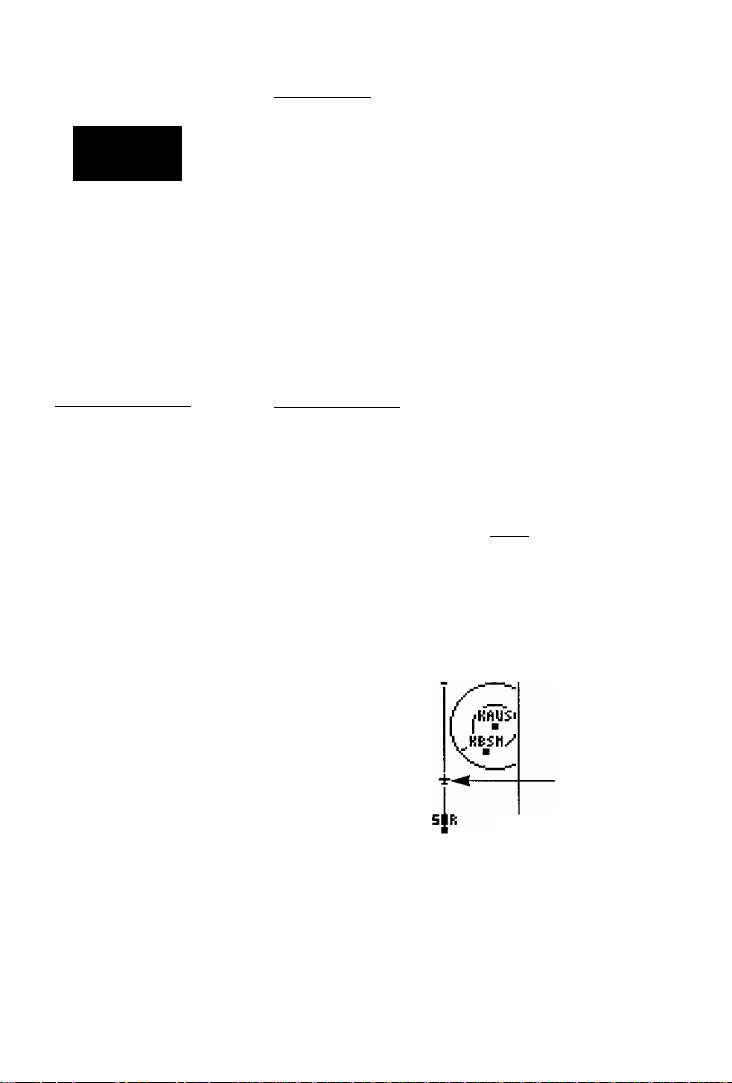
Once you’re back on the moving map page, you’ll
notice that our plane is getting dose to the special use air
space surrounding KAUS.
Whenever you are within 2 nm of an SUA, projected
to enter an SUA or inside an SUA, the GPSCOM 190 will
notify you with a message and supply detailed informa
tion on each SUA you are being alerted to. By looking
closely at the map display, you’ll notice that we will come
very close to the KAUS SUA, but not actually enter it.
Once our flight takes us within 2 nm of the SUA, we’ll be
alerted with a ’Near SUA < 2nm’ message (you may have
to wait a minute or so to get the message, depending on
how' fast you’ve made your way through the tour.
To view the SUA message:
® 1. Press!
Page 22

To return to the map page, press again.
Additional information, including the name, class,
controlling agency and altitudes, is available from the
key. To view additional SUA information;
Wo>'|)oinis Page
1. Press twice. The nearest SUA alarm page will
appear, which can display up to 9 SUA alerts at once.
Each listing will display the type of alert and your ETE to
intrusion, if applicable.
2. To view specific information on any listed SUA, highlight
the desired SUA name and press i
The SUA page will appear, providing additional
MRST FiLRH
1 AUSTIN
HEAR nm
information on floor and ceiling altitudes for the select
ed SUA.
3. To return to the nearest SUA list, press I
4. To return to the map page from the SUA list, press
Takeoff
TOUR
Nearesi
Alert messages for the various classes of SUAs may be
turned off to avoid nuisance alerts, and may also be
removed from the map to avoid excess clutter at higher
map scales. For complete information and definitions on
SUAs, see page 73,
Nearest Waypoints Page
The nearest waypoints page displays the nine nearest
airports, VORs, NDBs, INTs, and user waypoints to your
present position, and is extremely useful for locating the
nearest facility during an m-ilight emergency. In addition,
nearest flight services stations (FSS), Air Route Traffic
Control Centers (ARTCC), and special use airspace
alarms can also be viewed.
To view the nearest waypoints of a particular catego
ry, you need to select the desired category from the cate
gory field at the top of the nearest page. Let’s practice by
viewing the nearest airports to our present position;
1. Press twice to display the nearest page.
2. Press to begin selection of the desired category,
3. Scroll through the waypoint categories until 'APT
appears in the category field.
4. Press to confirm the category. The field highlight
will move to the first facility on the list.
136.75 119.00
The neamt
St/A
vides ir\jQrmation about
special use airspace alerts.
NEAREST rgrgj
MflVP-HT RRG
KHYI SDS'
HBStt DEE'
SDR i4S'
HHUS
T91 154'
3RS 9E5'
3R5 EDS'
T9D 197'
B3R ITS'
130.75
The hearing and distance to
the rune nearest airports
may be
the nearest airport pagejor
use in an emergency or/or
general information.
page pro
Di;
9.D9
11.5
lE.l
DD9‘
IE.a
19.1
EB.T
B3.7
ED. 4
3D.D
119.00
¿¡uichlv accesseti
on
Page 23

Takeoff
Tour
Com Pcfge
Sequaice
NEAREST 003
UAVPNT BAG PIS
lAK □SD' 133
ACK 359' 135
HQP 35S' 153
T4A 315' 15B
□E5' 114
sev 159
FZT □41'
DFU □□9' 1E7
ABl 3ir ITl
126.77
Informationon tile nine
ntrarerst VOfo is also avail-
ahk on ilic VOR page.
12^1
lEE
.68
Once you’ve selected and confirmed a category the
GPSCOM 190 vcitl display the nine nearest facilities and
provide the distance and bearing to each waypoint in the
list. To scroll and review the nearest waypoints list:
1. Highlight the desired waypoint,
2. Press review the waypoint page(s).
3. Press again to return to the nearest list. The field
highlight will sequence to the next waypoint on the list.
4. Press to exit the nearest function and return to
the previously viewed page.
Communication Page Sequence
Let’s continue the tour and look at the pages that con
trol the communications features of the GPSCOM 190.
Press twice to exit the GPS pages and enter the com
pages.
GPS
Page
ER& DST
325* 10.7Ì1.
325* 150"t
TRK SPD
3R9
ETE «TK
04:17 0.00R.
11:15
TIME UNfiy
Ì3Ì9~75'niElgH
Com Page
fi30Ì J5
119
KACV
flTIS
CLHO
UNCM
6ND
THR
DEP?
0BEES
ies.ee
127.85
122.85
121.90
120.80
124.60
J
The GPSCOM 190 features three com pages in a con
tinuous loop. Try scrolling through the pages by pressing
You can also scroll in the opposite direction
(or return to a previous page) by pressing
Page 24

The active and standby frequency fields appear at the
top of every com page. These fields allow you to enter a
frequency using the alphanumeric keys.
To enter a frequency from any com page;
T If you haven't done so yet, press twice to enter
the com pages from the GPS pages.
2. Highlight the 'STBY' frequency field.
3. Enter the desired frequency.
4. Press to confirm. The frequency you entered is
now the standby frequency. Press the frequency trans
fer button to place it in the active field.
The next available com page is the com frequency
page. The com frequency page gives you a complete list
of airport frequencies at the departure and arrival air
ports, allowing convenient selection of frequencies you’ll
need along your tlight path. If you do not have an active
departure airport, the com frequency page will display
the frequencies for the airport nearest your present posi
tion. If all of the frequencies are not visible, use the arrow
keys and scroll down.
At this point in the flight you’ll probably want to
select the destination airport approach control frequency
To select a frequency from the com frequency page:
1. Press repeatedly until the com frequency page
appears.
2. Use the arrow keys to highlight the approach frequency
for 3R9,119.00 Mhz.
3. Press The standby prompt is highlighted.
4. Press ^0. The 119.00 MHz frequency will move to the
standby frequency field marked 'STBY'.
To place 119.00 MHz in the active Held:
1. Press the frequency transfer button.
UHCfi 122.80
DEP 124.90
Rpp
UHCM 123.00
Selecting
the com frequency page.
FiTIS
CLNC
UHCh
GHD
THR
DEP?
The frequency of ¡19.00
MHz placed
field.
Takeoff
Tour
Nm'
Frequency!
List
130.75
119.00 5TET
50R
3R9
_____
a frequency from
119 .00 II
.GSn
KftCV
103.80
127.85
122.95
121.90
120.30
124.60
in the active
Page 25

Takeoff
TOUR
Emergenc}’
Channel
Sdcction
2nmm\ fOHUn
3B5' 5. IE
Emergency Channel Selection
The GPSCOM 190’s emergency channel selection fea
ture provides a quick method of selecting 121.5 MHz as
the active frequency in the event of an in-flight emer
gency The feature is available whenever the unit is on,
regardless of GPS or communication status, or unexpect
ed loss of the display.
To select the 121.5 MHZ frequency as the active
frequency:
1. Press and hold
r
1
1121 .5B
3B5’______________
119.60 123.65
AutoZoom at the 10 nm
scale.
/
t
1 pahIcfc
1 D.4D
ISO
3B4'
3B5*
130.75 119.00
AutoZoom at the
s£d!e.
I nm
[Sccinl ISe-ekl
1 Rcl 1 1 Wr-t 1
Signcil Strengih
u
To transmit on the emergency frequency:
s
1. Press the PIT switch.
Now let’s go back to the map page and finish up our
tour:
1. Press WiMtQ enter the GPS pages.
Auto Zoom
You will notice that as we make our way toward the
destination airport, the map scale will automatically
zoom in to provide a closer look at the airport. What
you’re actually seeing is the GPSCOM 190’s AutoZoom
feature. Whenever you select a GOTO destination, the
map page will default to the 80 nm setting and gradually
zoom down the map scale to the 1 nm setting.
Page 26

The map scale will zoom to the next lowest setting
(i.e,, from 80nm to 40nm) whenever the map can fit both
your present position and your destination on the screen.
If you manually zoom in the map scale before this
point, the AutoZoom feature will resume once it catches
up to the map scale you have selected (down to Inm).
If the map is manually zoomed out beyond the
AutoZoom scale, the AutoZoom will be canceled, and the
GPSCOM 190 will assume you want to stay at the scale
you have manually selected.
Canceling GOTO Navigation
By now, our plane should be approaching 3R9, the
destination airport. The map will continue to zoom down
to the Inm scale. To finish the tour and complete our
approach, let’s move back to the navigation page;
h Press to display the navigation page.
Once we fly past the airport, notice that the GPSCOM
190 continues to provide navigation to 3R9, with the rel
ative bearing pointer and ETE fields indicating w'e are
past our destination. The GOTO destination may be can
celed by activating another GOTO or canceling the cur
rent GOTO.
Takeoff
TOUR
Cancel GOTO
GO TO:
I
---
- PRESS ENTER TO
AOTIUATE
HAUIGATIOH
- PRESS GOTO TO
SEE NEAREST
UAVPOINTS^SUA
130.75 119.00
Cancel GOTO
l/se
the LEFT ARROW ky
to cancel GOTO navigation
and press ENTER
confirm.
io
GO TO:
I
---
- P-fiESS EUTER TO
fitTIUHTE
HHUIGATICH
- PRESS GOTO TO
SEE NEAREST
UAVPOINTS^SUH
130.75 119.00
To cancel the current GOTO:
1. Pressi
2. Press the left arrow key once to clear the destination
field (pressing the left arrow key clears a selected field
when the cursor is in the left most character position.)
3. Press
to confirm.
Page 27

Power Off
Power Off
Congratulations! You’ve now mastered some of the
basic features of the GPSCOM 190 and you’re ready to
take oft with a powerful tool that can help make your
bights smoother and more efficient.
To turn the GPSCOM 190 off:
1. Turn the volume control counterclockwise.
Thank you for choosing the GARMIN GPSCOM 190.
We hope it will be a valuable navigation and
communication tool for you, wherever your course may
take you.
Be sure to carefully review the sections on installa
tion and the internal database so you can get the most
out of your new GPSCOM 190, The takeoff tour has
only explored a smalt part of what this unit can do for
you. The reference section will describe in detail all of
the GPSCOM 190's functions and features.
Page 28

Internal Database
The GPSCOM. 190 uses an imernal Jeppesen® data
base to provide position and facility information for thou
sands of airports, VORs, NDBs and intersections. Each
facility in the database is stored as a waypoint, with its
ow'n latitude/longitude, identifier (up to six letters and/or
numbers) and other pertinent information. There are
three database coverage areas available for the GPSCOM
190. They are referred to as the “Americas”, “Atlantic
International”, and the “Pacific International” databases.
The International Civil Aviation Organization (ICAO)
and Aeronautical Radio, Inc. (ARINC) break the world
into ten geographic regions. The GPSCOM 190 Americas
database contains aeronautical information for the group
of ICAO regions consisting of North, Central, and South
America. The 'Atlantic Internattonal’ database provides
information for the ICAO regions of Europe, Africa,
Eastern Europe, and the Middle East. The Pacific
International database gives information for the ICAO
regions oi Eastern Europe, Middle East, Pacific, and
South Pacific.
Waypoint Categories
* •
Five categories of waypoint information are available
through the key Each categor)' provides different
types of detailed information for a selected facility:
• Airports— Identifier, city/state, country, facility
name, position (lat/lon), elevation, fuel services,
runways, and communications frequencies.
• VORs— Identifier, city/state, country, facility
name, position (lat/lon), frequency and co-located
DME or TACAN availability.
• NDBs— Identifier, city/state, country facility
name, position (lat/lon) and frequency.
• Intersections— Identifier, region/country, posi
tion (lat/lon) and range/bearing to nearest VOR.
• User— Identifier (name), position (lat/lon), user
comments and reference w'aypoint.
To view the w'aypoint information for a desired waypoint, select the waypoint category from the category
field, located at the top left of the waypoint page, next to
the identifier field.
Reference
Wa3i?OHii
Categoiies
%
HHERlCAf SUH
CYCLE
9607
EFFECTIUE
20 JUN 96
TO
18 JUL 96
The GPSCOM 190’$
nal Jeppesen database
available
witfi
Atlantic International, or
Pacific International data
base. The database cycle
is displayed on the
database information
in/ormation on updating
the database
with
your
GP5COM I90
inter-
an Americas,
page,
is
included
is
Page 29

Reference
To choose a waypoint category:
Enicrrng
W«3poifU
Identijias
HftVPOINT
APT: 500
LOCKHART nUH
LOCKHART TK
ELEU 53DFT
FUEL AU JET
RHUV-^COnn? DOHE-^
130.75 113.00
Efiiering
Idmtljicr
apt: KAUS
□UELLER.nUK-.
AUSTIN TK
ELEU E3DFT
FUEL AU JET
RHUV'^COnn'i DOHE-i
130.75 113.00
Entering
facility name.
_______
H 2$"51.0^13‘
W037N0.33^‘
HAVPOIHT
N 30^7.315’ W037*^2.095'
a waypoint by
1. Press to display the waypoint page.
2. Highlight the category field.
3. Press ^0 begin selection of the waypoint category.
4. Use the arrow keys and select the desired category.
5. Press to confirm the category selection.
Entering Identifiers
After a waypoint category is selected, information for
a waypoint can be viewed by entering the identifier or
name of the desired waypoint. Airports, VORs, and
NDBs may be entered by either the identifier, name, or
the location (city) of the facility. Intersections and user
waypoints must be entered by the identifier.
To enter a waypoint identifier:
1. Highlight the identifier field.
2. Enter the desired identifier and press
Note; As the identifier is entered, the GPSCOM 190
will scroll through the available database, displaying any
waypoints with the same identifier letters you have
entered to that point. Once the desired waypoint is dis
played, press
After you’ve selected a waypoint category, waypoint
information can also be retrieved by entering the facility
name of the airport, the name of the VOR or NDB, or
their city name (intersections and user waypoints cannot
be retrieved by facility or city name).
To select a waypoint by facility or city name:
1. Select the desired waypoint category (APT, VOR or
NDB}.
2. Highlight the facility name or city name field.
3. Enter the name of the facility or city and press
Once a waypoint category and identifier have been
selected, the GPSCOM 190 will provide extensive infor
mation through various waypoint review pages.
Page 30

Airport Information
Reference
UftVPOINT
ftPT! KAUS
ItUELLER HUH
HU3TIM T»
ELEU GSarT
N 38*17.915'
W097*‘12.095'
FUEL HU JET
RHuvT conn? raarraa
130.75 119.00
Location Page
WRVPOIHT
APT: KAUS
1 HTIS
119.20
E CLHC
125.50
3 GHD
121.90
4 TUR
121.00
5 UHOn
123.00
E DEFi
118.80
T DEPi
119.00
LOCH7l3rmna D4HE7
138.75 119.00
Communication
Page Punwo}'
The GPSCOM 190 features three airport pages:
• Airport location— allows entry of desired airport
by identifier, facility name or city and displays lat
itude, longitude and elevation; and fuel
availability
• Airport communication— allows entry of
desired airport by identifier and displays radio frequencies/usage.
• Airport runway— allows entry of desired airport
by identifier, displays runway designations, length,
surface and lighting information, and/or pilot con
trolled lighting frequencies.
To scroll through the airport pages:
1. Select the airport category and enter the desired airport
identifier. The airport page initially displayed will be the
same as the last airport page viewed.
2. Use the left arrow key to move the field highlight to the
desired page prompt and press Q).
Once you have moved from the initial airport page
displayed, the page prompt will automatically move for
ward to the next available prompt. This allows you to
continuously cycle through the airport pages by simply
pressing repeatedly.
To exit the airport pages and return to the previously
MRVPOINT
apt: KAUS
RUHUAV: UEHGTH
B7-3S 50D0FT
C0IIH7LACH7 D4HE7
130.75 119.
Page
Information
fiPT: KLAX
Li^s ANGELES XHTL
lOS ANGELES OH
ELEU 13DFT
H 33*56.556'
W 116*2^1.^13^1'
FUEL AU JET
RNUV-^COHH^
126.77 12^.90
The inlernal database
iCAO
port
names. Ai!
ports
which coniaiJi cmlv
leliers use the
For example,
International
under the
Other airports,
Otten Memorial
contain numbers in
identifier, do not require
%' prefix.
outside the V. S. use
letter prefixes. For more
information, contact the
international
Organization.
viewed page:
1. Press
Aii-pon
HavpoiHT
uses
identifiers for all air
U. S. air
prefix 'K'.
Los Angeles
is KLAX
ICAO standard.
such as
(3VS), that
Many countries
Civil
Aviation
the
the
two
Page 31

Reference
Location Page
Location Page
MfiVPOIHT
fiPT: KAUS
iftTis 11Э.20
г CLHO
3 CND
4 TMR
5 икси
Б DEPf
T DEPi
LOCMimrraa DOHE*^
125.50
121.90
121.00
123.00
118.80
118.00
130.75 118.00
in some instances, all avail
able jitcjnencies/or a select
airport
may
not jit on
and
view
are
(lie
to
any
also
ed
communication page, Use
the DOWN ARROWS’
scroll through
additional /reijuencies. In
addition to the frequencies
already mentioned, the fol
lowing
/reijuencies
displayed if available:
• Pre-Taxi
• Clearance Deliver}’
•
Approach
• Departure
• Arrival
• Class В
and C
» СТА
• IMA
• TRSA
Facilit} Name
(selectable)
CityState
(selectable)
HflVPOINT
ftPT: KAUS
HUELLER HUN
HU^TIH TK
ELEU B3QFT
Elevation &
N 30"17.815‘
W097"^2.095’
FUEL RU slET
KHHVÌCOHHÌ гадпэд
Identifier Field
(selectable)
Position
Available
Fuel T}pes
130.75 119.00
The GPSCOM 190’s airport location page displays the
latitude, longitude and elevation of the selected airport,
as well as fuel availability From the airport location page,
you can enter a desired airport by identifier, facility name
or city as described on page 24. The following descrip
tions and abbreviations are used on the airport position
page:
•Elev— Elevation in feet or meters
•Position— In the position format you have current
ly selected from the setup page
•Fuel— Lists the types of fuel available at the airport:
•AV gas— 80-87 octane, 100 LL, 100-130 octane
•JET— jet A, jet A-1 or jet A-r
•MOGAS— 87 octane unleaded
Airport Communication Page
The airport communication page (shown in the left
margin) displays radio frequencies and their usage for the
selected airport, and allows entry of a desired airport by
identifier only The following frequencies are displayed if
available (see left margin for additional frequencies):
•ATIS— Automatic Terminal Information Service
•Gmd— Ground
•Twr— Tower
•Uncm— Unicom/Multicom
Page 32

Runway Page
The last airport page is the runway page, which fea
tures a diagram ol available runways, along with designa
tions, length, surface and lighting information for the
selected airport.
Reference
Page
Runway
Deii^ator Field
(sdectabk)
Runway
Diagrams
UftVPOIHT
fiPT: KAUS
RUHUAV: LENGTH
\
□Т-ЗБ SDDDFT
^URFHOE LIGHTING
HHRD FULL TIME
COnH-^LOON-i DONE-i
Idcntijier
Fie!d
fseieciable)
Runway
Data
130.75 119.00
The runway diagram provides a north-up graphic of
available runways, with length, surface and lighting data
listed below the runway designation. The 'SURFACE'
field will display one of the following surface types; hard,
turf, sealed, gravel, dirt, soft, unknown or water. The
‘LIGHTING’ field will indicate one of five lighting
schemes: part time, full time, pilot controlled (w'ith fre
quency), no lighting or unknowm.
If a selected airport has more than one runway, addi
tional runways can be viewed by selecting another run
way from the designation field.
To view additional runways:
1. Highlight the runway designation field.
2. Press I
3, Use the arrow keypad to toggle through and select the
desired runway.
4. Press to return the cursor to the 'DONE?' prompt.
UftVPOIHT
ftPT: KAUS
RUHUHY: LENGTH
□T-3S SQQDFT
LIGHTING
HARD FULL Т1ИЕ
COntlYLOCH*^
130.75 119-00
Additional
runways
accessed through the run
way designation field.
MftVPOIHT
ЙРТ: KTCS
RUHHAY: LENGTH
□3-31 55DDFT
\
fURFROE 1LIGHTING
HRRD
126.77
Pilot-controlled
witii ¡isteti
1гг.BD
DGNE-i
12^.90
iigfiting
frequency
are
Page 33

Reference
fnferseciioits,
NDBs & VORs
Intersection Information
The intersection waypoint page allows entry of a
desired intersection by identifier, and displays position
and nearest VOR data for a selected intersection.
To view waypoint information on an intersection:
1. Select the intersection category from any waypoint field.
2. Enter the identifier of the desired intersection and press
HftVP-OINT
IHT: AADCO
H ^5^7.097'
W093M2.^100'
REF:0EP
BEARING DISTANCE
038^ 10.9^
NCEN USA
IM!ia
126.77 119.00
Intersection Page
NDB Page
The unit will display the intersection’s latitude and
longitude below the identifier field, and calculate the
bearing and distance to the nearest VOR. Note that the
displayed VOR may not be the VOR used to define the
intersection. The region and country of the intersection
will also be displayed at the bottom of the page to help
you confirm the location in the event of duplicate
identifiers.
NDB Information
The NDB waypoint page allows you to select a
desired NDB by entering the identifier, facility name or
city. In addition to displaying the identifier, facility name
and city/state of the NDB, the NDB page will show the
latitude and longitude of the facility the region/country,
and the com frequency.
To view waypoint information on a NDB;
1. Select the NOB category from any waypoint category
field.
2. Enter the identifier, facility name (on the second line) or
city (on the third line) of the desired NDB and press
VOR Information
The VOR waypoint page allows you to enter a VOR
by identifier, facility name, or city name and displays
the selected facility’s position, frequency and other
information.
To view waypoint information for a VOR:
1. Select the VOR category from any waypoint category
field.
2. Enter the identifier, facility name or city of the desired
VOR and press'
Page 34

The VOR page lists the identifier, facility name and
city/state of at the top of the page, with the transmitting
frequency of the facility listed below. If DME or TACAN
equipment is co-located at the site, it will be indicated
next to the transmitting frequency of the VOR. The lati*
tude and longitude is also displayed, with the region and
country indicated near the bottom of the page.
User Waypoint Information
The last waypoint category available from the
GPSCOM 190’s WPT key is user waypoints. The user
waypoint page allows entty^ of a desired waypoint by
name/identifier and displays the waypoint’s position, user
comments and a reference waypoint field to calculate the
distance and bearing to any other waypoint in the data
base. The user waypoint page can also be used to create
up to 250 waypoints by manually entering a position or
defining a range and bearing from an existing waypoint.
To view waypoint information for a user waypoint:
1. Select the USR category from any waypoint category
field.
2. Enter the identifier/name of the desired user waypoint
3. Press I
The user waypoint page allows you to create new
waypoints three ways;
• Enter the exact position of the new waypoint.
• Reference a waypoint already in the database.
• Enter a distance and bearing from your present
position.
To first step in creating a new waypoint (regardless of
what method you’re using) is to assign a name/identilier
for the new waypoint.
To create a new waypoint from the user waypoint
page:
1. Select the 'USR' category from any waypoint category
field and press The highlight will advance to the
name field.
2. Enter the waypoint name.
3. Press to accept.
Reference
VORs & User
HflVPOINT
UOR: ABB
HAEE IN
112. ¿10MHz DME
H 38^35.327'
W085*38.18r
GR LKS USA
126.77 118.00
VOR Wf^oint p a g e
HflVPOINT
USR: GARM IN
N 30*01.
W097*^16. S'le'
ZD-JUH-9E 15:3S
REF: ,
PRO
m5*
RENAME? MEH?
DELETE? gaZM
126.77 119.00
Oserwi^oiitt p a g e
DST
3.21R.
Page 35

Reference
Cmiting User
Wo>poutis
MflVPOIHT
USR: TOWES-
REF:
BRO
RENftME'? NEW?
DELETE? DONE?
130.75 119.00
Entering a new
point’s name.
HftVPOINT
USR: TOWER
H 35^29.180'
W107^20.600
REF:
BRG
lAT
RENflriE? NEH?
DELETE? DONE?
130.75 119.00
Entering
polrifs position.
DST
user
way
DST
1.68J
a new user way-
Once the name has been accepted, the field highlight
will move to the position field, where you can manually
enter the position of the new waypoint:
1. Enter the lat/lon.
After the latitude and longitude entry is complete,
press to save the new waypoint. If you are defining
the new waypoint position by referencing (entering a dis
tance and bearing from) a knowTi waypoint or your pre
sent position:
1. Highlight the 'REF field.
2. If you are referencing a waypoint enter the identifier of
the reference waypoint (If you want to reference your
present position, leave the 'REF field blank.}
3. Press
. The field highlight will advance to the bear-
ing field.
To enter a bearing and range from the reference
position;
1. Enter the bearing of the new waypoint from the refer
ence position.
2. Press to confirm the bearing. The field highlight
will move to the distance field.
3. Enter the distance of the new waypoint from the refer
ence position.
4. Press to confirm the distance. The GPSCOM 190
will calculate the coordinates of the waypoint and store
it in memory.
User Comments
Once a new' user waypoint is saved, the unit will
assign a default user comment (the date and time of
creation) to the new' waypoint. You can replace the
delault comment to your own 16 character comment at
any time, right from the user w'aypoint page.
To enter a user comment:
1. Highlight the comment field.
2. To clear the default comment, press the left arrow key
when the cursor is in the left most character position.
3. Enter the comment and press
Page 36

The delete and rename prompts, located near the bot
tom of the user waypoint page, allow you to quickly
remove a waypoint trom memory or change the name of
an existing waypoint.
To delete a user waypoint:
T Highlight'DELETE?' and press i
2. Highlight'YES?'and press i
The user waypoint page also allows you to rename
any user waypoint in memory.
To rename a user waypoint:
1. Highlight 'RENAME?' and press Qp. The rename waypoint page will appear.
3. Enter the new waypoint name,
4. Press Gp. The highlight will advance to the 'Yes?'
prompt.
5. Press to accept the name, or
cancel.
Creating Waypoints with AutoStore
The key is also used to save new w^aypoints
using AutoStore. AutoStore allows you to quickly store
your present position and add the new' waypoint to a
selected route if desired.
To save your present position using AutoStore;
1. Press CD twice to capture your position (if you're
already on a waypoint page, you'll only need to press
theCw ^^Y once).
The AutoStore page will appear, showing the cap
tured position and a default 3-digit waypoint name. To
change the default position name :
1. Highlight the name field and enter the name.
3. Press QD- The highlight will move to the 'route' field.
Reference
User Wa>|io/nis
CvAiiio5iorc
HAVPOIMT
U£R: 3R5
N 30^07.21^1'
W037^50.570'
REF: KIXD
BRO DST
193^ 00.0ii.
RENftHE'i MEH'?
DELETED DONE?
126.77 119.00
Entering
a distance from a
reference waypoint.
UflVPOIMT
USR: 3R5
H 30^07.214
W097*50.570’
ref: KIXD
BRG DST
193^
REHRHE'T MEM'?
126.77 119.00
Deleting
5A2V.
DOME?
a user waypoml.
If you’d like to add the waypoint to a route:
1. Press and enter the desired route number using
the arrow keypad and press QH ^o confirm.
To save the AutoStore waypoint:
1. Highlight the 'SAVE?' field and press i
Page 37

Reference
Ne«rcsi Pages
MERREST FSS
FfiCILITV
£AH AHGELC
BRG DST
035^ 12. IR.
FRECUCNOV
122.55
130.75 119.00
Neanesi FSS Page
HERREST BTR
FACILITY
KANSAS CITY
BRG PST
254^ 39.4K.
FAECUEHCIES
120.50
123.80
138.97 119.00
Nearest ARTCC Page
Nearest Pages
The key provides detailed intormation on the
nine nearest airports, VORs, NDBs, INTs, and user waypoints to your present position, and is extremely useful
lor locating the nearest facility during an in-flight emer
gency In addition, nearest Right services stations (FSS),
Air Route Traffic Control Centers (ARTCC), and special
use airspace alarms can also be viewed.
To view the nearest waypoints of a particular categor)' (airports, VORs, NDBs, intersections or user waypoints), you need to select the desired category from the
category field at the top of the nearest page. Let’s practice
by viewing the airports nearest to our present position:
1. Press
2. Press
3. Press the down arrow key repeatedly to scroll through
the waypoint categories until 'APT' appears in the cate
gory field.
4. Press to confirm the category. The field highlight
will move to the first facility on the list.
Nearest Flight Service Station/ARTCC
The nearest function also gives you detailed informa
tion on the nearest FSS or ARTCC, The nearest FSS or
ARTCC page displays the facility name, bearing and dis
tance from your present position, and the facility's fre
quencies. To view the nearest FSS or ARTCC, you need to
select ‘FSS’ or ‘CTR’ from the category field at the top of
the nearest page. Let’s practice by viewing the nearest FSS
to our present position:
1. Press
2. Press
3. Press the down arrow key repeatedly to scroll through
the categories until 'FSS' appears in the category field.
4. Press confirm the category. The field highlight
will move to the FSS frequency for selection as the
standby frequency.
twice to display the nearest page,
to begin selection of the desired category.
twice to display the nearest page,
to begin selection of category.
Page 38

Transceiver Description
The GPSCOM 190 is a 760'channel digital VHP avi
ation communication transceiver with the following
features :
•Transmits and receives on the VHF aviation com
munication frequency band which extends from
118.000 to 136.975 KHz, in 25 kHz steps.
•Receives ten weather frequencies, including all
NOAA and most Canadian weather radio channels.
The weather receiver has scanning capability plus
severe weather alert tone detection.
•Receives the aviation VHF NAV (VOR/Localizer)
band which extends from 108.000 to 117.950 MHz
(audio only no navigation capability).
Frequency Entry - Com Pages
You can quickly enter a frequency from a com page.
The GPSCOM 190 will always display the active frequen
cy at the top of every com page and the standby frequen
cy below it.
To enter a frequency from any com page:
1. If you haven't done so yet, press twice to enter
the com pages while viewing the GPS pages.
2. Enterthe desired frequency in the highlighted standby
frequency field. Note: you cannot directly enter a fre
quency into the active field.
3. Press to confirm. Press the frequency transfer
button to select the standby frequency as the active
frequency.
To transmit on the active frequency:
Reference
Frequenc^^
Entij/Com
Pages
Transceiver specifications
for
the GPSCOM
located in Appendix B.
IMPORIANTl
If the GPSCOM 190 is to be
used in an
craft radio license
required. If
used as a ground station,
then
ground station
rization
is
page a for guidance
licensing
190 are
aircraft, an air
is
tiie unit is io
autho
required. See
on
requirements.
be
1. Press the PTT switch.
Page 39

R EF“ERENCE
Com Fimcifon
Page
Com Page Sequence
The GPSCOM 190 features three com pages in a con
tinuous loop: com function, com frequency, and com
menu. Try scrolling through the pages by pressing the
key. You can also scroll in the opposite direction (or
return to a previous page) by pressing'
Mxei
119.00
Sccinl Seek
Signal Strength
u s
Com Function Page
STEV
Press
tion page.
Com Function Page
The com function page controls scanning and seeking
and memory writing and recalling. The com function
page also displays a signal strength indicator in bar graph
form that shows the relative strength of a received signal;
W for weak, S tor strong.
Scanning
How many times have you been on the ground near
an airport and wanted to scan ail the local frequencies? If
you have used another handheld radio, you may have
looked up the frequencies and entered them manually
into memory channels, and scanned those. That process
is a lot of work, especially if you want to turn around and
do the same thing at another airport. The GPSCOM 190
allows you to scan all of the frequencies for the nine near
est airports (excluding ATIS) in the default scan mode
(see scan mode setup submenu on page 39).
repeatedly until you access the com func-
Page 40

when the GPSCOM 190 is scanning, it goes through
the frequencies included in the scan, one by one, and
stops on an active frequency. When scanning, the right
side of the active frequency box displays GCAN’. When
scanning stops (signal is detected), you will hear the
transmitted audio and the word ‘SCAN’ is replaced with
the letters ‘RX’. Once the signal has gone inactive for two
seconds (the default scan delay), the GPSCOM 190 will
resume scanning until it detects another signal. See page
40 for instructions on how to change the scan delay.
To scan:
1. Highlight the graphic 'Scan' button and press
Scanning can be stopped in three ways:
• Break squelch by turning the squelch control counter
clockwise until audio is heard (scanning wilt resume
once squelch is restored).
• Press the PIT switch or the frequency transfer button.
• Press on the highlighted 'Scan' button. Once the
unit has stopped scanning, you can press and
cycle the unit through each frequency in the scan list
you have selected.
Seeking
The GPSCOM 190s seek mode is similar to scanning
operation, without the delay function. When the unit is
seeking, it goes through the selected frequencies, one by
one, pausing on an active frequency. Once the receiver
pauses on a frequency it will remain stopped until you
start seeking again. This allows you more “hands on” con
trol. When the receiver pauses you will hear the trans
mitted audio and the word ‘SEEK’ will be replaced with
‘RX’.
To seek:
1. Highlight the 'Seek' button and press CB-
To stop seeking do any one of the following:
Reference
Scanning and
Seeking
119.92
130.75
Scan Mode:
COM Band
Direction:
Up
Delay:
Ш2
second;
Entering
a scan delay on
the com Junction page
.
120.97 iEE«
119.BB sTiv
SconJ
Wrt I
Signal Strength
The GPSCOM 190
mode.
in seek
• Break squelch.
• Press the РТГ switch or the frequency transfer button.
• Press on the highlighted 'Seek' graphic button.
Page 41

R E F' E R E N C E
Ma\myfCom
Frequency Page
130.75
119.00 STEV
IScctnl I Seek I
[
Write 130.75
to channel_^
CUIT-i
Writing
a frequency
memory.
130.75
119.00 STEV
Scan! Seek
01 118.00
CUIT?
Recalling
a frequency from
memory.
into
Memory Write and Recall
Memory writing allows you to store your favorite com
frequencies in memory.
To write a frequency into memory:
1. Highlight the 'WRT' box and press
2. Highlight the 'Write' field and enter the frequency.
3. Press The 'SAVE?' field is highlighted.
4. Press i
You can recall a frequency from memory and place it
m the standby frequency field.
To recall a frequency:
1. Highlight the 'Rd' button and press
2. The highlight will move to the first occupied memory
channel. Use the alphanumeric keys to enter the chan
nel number you want to recall and press
3, Highlight 'USE?' and press i
4, If no memory channels have been programmed, a mes
sage box will appear saying "No memory channels have
been programmed". Press to clear the box.
Com Frequency Page
126.77
118.00 ST&V
50R
UHcn 122.S0
DEP 12^.90
3R9
ftpp 119.00
UHCM 123.00
The second com page is the com frequency page. The
com frequency page provides a list of the airport fre
quencies at your departure (or nearest) and destination
airports, allowing convenient selection of frequencies
you’ll need along your flight path. From the com page
sequence, press until you see the com frequency
page.
Page 42

From the com trequency page you can select a fre
quency and place it into the standby frequency field or
into memor}t
To select a frequency and place it in the standby fre
quency field:
Freqmnq’
fif/ornmiion
Page
1. Highlight the desired frequency and press^®.
highlight will move to 'STANDBY?'. Press
The frequency you have selected is now placed in
the standby frequency field.
To select a frequency and place it in memory:
1. Highlight the desired frequency and press Use
the arrow keypad and highlight 'Memory?'. Press .
The frequency you have selected is now entered into
the next available memory channel.
Frequency Information Pafte
If a frequency has sector or altitude restrictions, the
frequency type wall be iollow'ed by a question mark.
The
138.
119.75BB
KACV
UMCn
OHD
TUR
iq^ad
DEP-?
OL£ C-T
122.35
121.30
120.30
12^.60
13^.25
12^.60
130.75
119.00 îTfï
KACV
flTIS
CLNC 127.85
UNCt
ÛND
TUR
DEP'l
Selecting a frequency and
placing
field.
FREOUENCV INFO
tEARIHC
003" ” 170^
ftLTITUDE
NONE
KARRATIUE
NOME
103.80
MEMORY? 1
120.30
i 12^.60
it into tiie
standby
To view the frequency information page:
1. Highlight the type field.
2. Press . The display will show you the frequency
information page, with bearing, altitude, and narrative
restriction information.
126.77 113.00
Frequemy In/ormation
Page
Page 43

Com Mam
Poge
130.75
119.00
con riENU
Sc«n
Seek
Memory
Com Menu Page
Com Menu Page
The com menu page allows you to customize com
munication setup. It displays the com menu list which
allows you to select the com, scan, seek or memory
setup pages.
To select a submenu from the com menu page:
1. Highlight the submenu you want to select
2. Press to display the submenu page.
3. To return to the com menu page,
Com Setup Submenu
From the com setup submenu you can select an oper
ating mode, set ‘Stuck Mic’ timing, and setup for VOR
duplex operation.
There are three modes of operation; ‘On’ (the default
setting), ‘Off’, and ‘Wx’ (weather). Selecting ‘Off’ turns off
the transceiver, allowing only GPS operation. Select ‘Off
if battery life is a concern.
To turn the transceiver off:
1. Highlight the'COM mode'field and press
2. Use the arrow keypad to select 'Off and press
130.75
119.00 sTfv
COM Mode;
Stuck Mic:
35 seconds
VOR Duplex:
122.1©MHz
Com 5eiup Submertu
Weather Mode
Selecting ‘Wx?’ accesses the weather alert page where
you can mute the receiver. Muting the receiver allows you
to hear severe weather statements and warnings only, not
the continuous normal broadcasts. In the mute mode, the
receiver remains silent until the National Weather Service
transmits a severe weather alert tone. Once the tone is
received, the unit sounds a message beep and the center
of the page displays the message ‘Alert Tone Detected’.
The unit automatically unmutes, enabling you to hear the
severe weather statement, and will remain in this mode
until the mute mode is reselected.
To mute the receiver:
1. Highlight the 'Audio' field and press
2. Press to select 'Mute'.
3. Press to exit the weather alert page.
Page 44

Stuck Microphone Timinfi
The stuck mic feature disables the transmitter after a
selected length of time in the event of an open micro
phone or faulty transmitter.
To enter a stuck mic time:
1. Highlight the 'Stuck Mic' field.
2. Enter a time of up to 99 seconds and press
Refefíence
Com Menu
Page Options
VOR Duplex Operation
There are times when voice features are used on a
VOR frequency by АТС or FSS for transmitting instruc
tions or information to pilots. The GPSCOM 190’s VOR
duplex feature allows you to transmit on a com frequen
cy and receive on a VOR frequency.
To use VOR Duplex:
1. Enter the desired VOR receive frequency in the standby
frequency field and push the frequency toggle button to
make it the active frequency,
2. Highlight the VOR Duplex field and enterthe desired
com frequency.
3. Press the PIT switch. The VOR Duplex (com) frequency
will become the transmit (active) frequency.
4. When the PTT switch is released, the unit will receive
transmissions on the VOR frequency you entered in
step one.
Scan Setup Submenu
The scan setup submenu allows you to customize the
GPSCOM 190’s scanning features. It displays scan mode,
direction, and delay.
The scan mode field allows you to to select a group of
frequencies to scan: Nearest List, Memory, COM Band,
and weather frequencies.
The GPSCOM 190 features four scanning modes:
• Nearest List scans the list of nearest airport fre
quencies.
• Memory scans all programmed memory channels.
* •
fìudio:
COM Mode: On
Stuck Mic:
VOR Duplex:
Changing a VOR
frequency.
HXBl X»
119.00 STtv
Urimuted
Ho filert Tone
De'tec'ted
PRESS COM KEV
TO QUIT
Audio
mute
ofííion.
HX 05
124.00 STEV
35 seconds
122. lElMHz
duplex
Page 45

Reference
Setup
Menu
• Com Band scans the VHP Com Band from 118.00
to 136.975 MHz.
• Wx Channels scans all 10 weather channels.
To select a scan mode:
1. Highlight the 'Scan Mode’field and press
2. Use the arrow keypad to select a mode and press
130.75
119.00 sTfv
Sc«n Mode:
BOM Band
Direction:
Up
Delay:
2 seconds
Sefeciing
a scan mode.
130
75
119
0B
Seek Mode:
COM Band
Direction:
Up
Seek Setup Submenu
The highlight moves to the ‘Direction’ field where you
can select an ascending (up) or descending (down) scan
ning order.
To select a scanning direction:
1. Press on the highlighted ’Direction' field.
2. Use the arrow keypad to choose a direction and press
The highlight moves to the ‘Delay’ iield. After each
transmission has ended, you may want to enter a delaygreater than the default setting of two seconds, ensuring
that you’ll hear both sides of a conversation before the
unit starts scanning again. This delay is put on all chan
nels.
To enter a time delay:
1. Enter a time up to 99 seconds and press
Seek Setup Submenu
The seek setup submenu allows you to customize the
GPSCOM 190s seek features. Unlike scanning, seeking
gives you more “hands on" control. Seeking lets you pro
ceed at your own pace letting you stay on a stopped fre
quency as long as you like. This will allow you to contin
ue to hear a conversation containing pauses. Once the
receiver stops on a seek frequency, it will remain stopped
until you break squelch, press PTT or the frequency
transfer button.
To select a seek mode and direction:
1, Highlight the 'Seek Mode' field and press
2. Choose a mode and press The highlight moves to
the direction field where you can press choose a
direction and press ^^again.
Page 46

Memory Setup Submenu
The memory setup submenu lets you manage the
memory features of the GPSCOM 190 including locking
out frequencies. Any frequency locked out will be
skipped over during scanning. For example, if you are
scanning all the frequencies in memory for a particular
airport which has ATIS, the scan will stop on ATIS and
never resume scanning, because the ATIS transmission is
continuous. Locking ATIS out will prevent the
constant stopping.
To enter a frequency into an empty memory channel:
1. Highlight the memory channel frequency field.
2. Enter the desired frequency and press to confirm.
The highlight will move the lock icon where you can lock
the frequency by pressing
3. Unlock the frequency by pressing again.
Memory Comments
Each channel may be given a 15 character user
comment.
To enter comments:
1. Highlight the comments field.
2. Enter up to 15 characters and press
moves to the next memory position,
Memory Changes
There may be times you’ll want to change or insert an
existing frequency and it’s corresponding comments in
memory.
To change a frequency in memory:
.The highlight
Reference
McTHory Setup
Siiliiiiemi
MX 05
124.90 STEV
1D21.50 A
2
__________
Entering
memory.
S
a frequency into
MX 01
119.00 STEV
1 113.00 A
3
__________
a
1. Highlight the frequency field and press
2. Use the arrow keypad to select 'CHANGE?'.
3. Enter the new frequency
4. Press to confirm.
To change comments in memory:
1. Highlight the comments field.
2. Enter the new comments and press'
Entering
ments.
frequency com
Page 47

Reference
Frcquenc}^
Selection
Hxei
119.8B sTsv
CHRH&E^ L
INSERT'?
msm^
:
3
_______
Removing a frequency from
memory.
Memory Changes (cont.)
To insert a frequency into memory;
1. Highlight the frequency field and press i
2. Use the arrow keypad to select 'INSERT?'.
3. Enter the new frequency.
4. Press CB confirm.
To remove a frequency in memory:
1. Highlight the frequency you wish to remove and press
2. Select 'REMOVE?'
3. Press'
Emergency Channel Selection
1. Press and hold
r
}
112 1 .50
IScciii
i| jSeek|
1 Rci
] ! wrt 1
Signal Strength
u s
The GPSCOM 190’s emergency channel selection fea
ture provides a quick method of selecting the 121.5 MHz
frequency as the active frequency in the event of an in
flight emergency. The feature is available whenever the
unit IS on, regardless of GPS or communication status, or
in the unlikely loss of the of display.
To select the 121.5 MHZ frequency as the active
frequency:
1. Press and hold
To transmit on the emergency frequency:
1. Press the PTT switch.
Page 48

Going To a Destination
Reference
One ol the many benefits of GPS navigation is the
ability to fly directly to a waypoint or fly along a chain
of waypoints without relying totally on ground-based
navigation aids. To take advantage of the convenience
and efficiency of point-to-point GPS navigation, the
GPSCOM 190 provides three methods of selecting a
destination for your flight: GOTO, TracBack and route
navigation.
The GOTO function provides a fast way to set a
course to a destination from your present position,
while the route function allows you to create a chain of
waypoints to follow in sequence toward a selected desti
nation.
ACTIVE FROM- WAYPOINT
ACTIVE LEG
MAP ACTIVE TO WAYPOINT
GOTO & Route
Na\igation
Whether you're Hying a GOTO course or a route,
there are a few basic concepts and terms that apply to all
point-to-point GPS navigation. Routes are broken down
and navigated in smaller segments called “legs”. The dia
gram above shows a basic route consisting of five waypoints and four legs.
The waypoint you are going to in a leg is called the
“active to” waypoint (MAP), and the waypoint immedi
ately behind you is called the “active from" waypoint
(SGF). The line between the “active to” and the “active
from” waypoint is called the “active leg”. When you acti
vate a route with the GPSCOM 190, it will automatically
select the route leg closest to your position as the active
leg, and provide navigation guidance directly to the
“active to” waypoint of that leg.
Page 49

Reference
GOTO Kq
GO TO:
I
---
- FRESS ENTER TO
ROTIURTE
NRUIGRTIOH
- PRESS GOTO TO
SEE NEAREST
UAVPOINTS/^SUA
126.77 119.00
Jo cancel GOTO naviga
tion,
use
the LEFT
ARROW
key to dear the identifier
Jield, and press
NEAREST UOR
HAVPNT &RG PIS
LOA IIB
lAH □BE' ISB
ACN 35E' 153
ttHF
FZT □ 34' 173
lift 31E' 179
DFU □□5' 193
ARI 319' 193
121.50 12A.90
Vou
waypoints
GOTO page by pressing the
GOTO key twice.
ENTER
□IB' ITB
24W 173
may access the
page Jrom the
nearesi
GOTO Function
The GPSCOM I90’s GOTO function lets you choose
any stored waypoint as a destination and quickly set a
course from your present position. Once a GOTO has
been activated, the navigation page will provide you with
steering guidance to your destination.
To activate the GOTO function:
1. Press'
2, The GOTO page will appear with the waypoint field
ready to select a destination. Enter identifier destination
waypoint.
3. Press
Waypoint
field
Name
to confirm the waypoint.
GO TO:
-3RS
________
- PRESS ENTER TO
RCTIUHTE
NflUIGRTION
- PRESS GOTO TO
SEE NEAREST
UAVPOINTS.^S«A
----------
GOTO Options
126.77 119.00
You can also quickly activate the GOTO function
from any other page by simply highlighting an identifier,
pressing the key and confirming the GOTO page.
This method can be used to re-center the GDI on the des
tination waypoint, or to fly a route out of sequence.
Once a GOTO is activated, the GPSCOM 190 will
provide navigation guidance to the selected waypoint
until the GOTO is cancelled.
To cancel an active GOTO:
1. Press
2. Use the left arrow key to clear the field.
3. Press to complete the cancellation.
*
Page 50

TracBack Navifiation
Another method of navigating to a destination is by
using the TracBack function, TracBack allows you to
quickly and easily retrace your path using the track log
automatically stored in the receiver’s memor>t The advan
tage of TracBack is to eliminate the need to mark waypoints along the way and manually create and activate a
route back to where you began your trip.
The TracBack route is created by reducing your cur
rent track log into a route of up to 30 waypoints, and acti
vating an inverted route along those points. Once activat
ed, a TracBack route will lead you back to the oldest track
log point stored in memory so it’s usually a good idea to
clear the existing track log at the start of your current trip
before you take off.
To clear the track log and define a starting point for a
TracBack route:
1. From the setup menu or map configuration page, high
light the 'TRACK LOG' option. Press to access the
track log page.
2. Use the up arrow key to highlight the 'CLEAR TRACK
LOG?'option.
3. Press ^0. The clear log confirmation page will
appear. Use the left arrow key to highlight the 'Yes?'
prompt and press
To activate a TracBack route:
1. From the the setup menu or map configuration page,
highlight the 'TRACK LOG' option. Press CB to access
the track log page.
2. Highlight the 'TRACBACK?' option and press ^0.
Once TracBack has been activated, the unit will take
the track log currently stored in memory and divide it
into segments called degsT Up to 30 temporary waypoints (e.g., TOOT) will be created to mark the most sig
nificant features of the track log in order to duplicate your
exact path as closely as possible. A TracBack route from
your present position to the oldest track log point will be
created as the active route (the active route page will
appear), and provide steering guidance to each waypoint
back to the starting point of your track log.
Reference
TracBack
Navigation
TRACK LCC
RECORD TRRCK:Vef
CRITERIA:
flufomatic
HEHORV USED IX
37 OF BD4B PHTS
TRAC6HCK?
CLEAR TRACK LOG';
126.77 119.00
To dsjine the
for TracBack navigation,
dear the track
kginning
RECORD TRACK: VeS
CRITERIA:
starting point
log at
of each trip.
TRACK LOO
the
flutomatic
HEHORV USED IX
3B OF ZUAB PHTS
CLEAR TRACK L0G7
126.77 119.00
To begin navigation of a
TracBack
route, higfiiigfit
the TRACBACK?'
and press ENTER.
prompt
Page 51

Reference
TracBack
Navigation
The
TracBack function
iii!ows}'ou to
track log hack
track point
navigate your
to the oltiest
in
memory.
RCTIUE ROUTE
UftVPHT
TDD3
TDDE
DTK
__
* _ . __
PIS
TDDl DD7' SEE
CLEAR?INVERT?
119.00126.77
To save
a TracBack route,
be
sure to
copy route 0
another route. To
temporary waypoint,
piy
rename it/ol!owing
mstruefions on
page
save
sim-
3].
to
the
Tips on Creating and Using the TracBack Feature
The GPSCOM 190’s TracBack feature is designed to
help you quickly create and activate a route that follows
your path back to a user-defined starting point. To get the
most out of the TracBack feature, remember the following
tips;
• Always clear your track log at the exact point which
you will want to go back to (airport, landing field,
etc.),
• The ‘RECORD’ option on the track log setup page
must be set to the ‘Yes’ position,
• There must be at least two track log points stored in
memory to create a TracBack route,
• If there are not enough available waypoints in
memory to create a TracBack route, you will be
alerted with a ‘waypoint memor)'^ full’ message. The
receiver will use any available waypoints to create a
TracBack route with an emphasis on the track log
closest to the destination (the oldest track log point
in memory).
• II the ‘CRITERIA option on the track log setup page
is set to a time interval, the TracBack route may not
follow your exact path (keeping the criteria set to
automatic will always provide the best TracBack
route).
• If the changes in direction and distance of your
track log are very complex, 30 waypoints may not
be enough to accurately mark your exact path. The
receiver will then assign the 30 waypoints to the
most significant points of your track and simplify
segments with fewer changes in direction.
• If you want to save a TracBack route, copy route 0
to an open storage route before activating another
TracBack. Activating another TracBack or storage
route will overwrite the existing TracBack route.
a
• Whenever a TracBack route is activated, the receiv
er will automatically erase any temporary waypoints (e.g., ‘TOOT) that are not contained in routes
1-19. If there are temporary waypoints stored in
routes 1-19, the receiver will create any new tem
porary waypoints using the first three-digit number
available.
Page 52

Route Defijiition Page
The GP5COM 190 lets you create and store up to 20
routes of 30 waypoints each. Routes are created, copied
and edited through the route definition page, which is
accessed through the main menu page.
To select the route definition page:
1. Press until the main menu page appears,
2. Use the arrow keypad to highlight the 'Routes' option.
3. Press QB display the routes page.
4. To return to the main menu page, press'
Route Number
Distance to
Wnypoirti
Route
Waypoints
Route Function
Fields
copy TO’Md
The route number field is displayed at the top of the
page, with a 16-character comment field below. If no user
comment is entered, the field wall display the first and last
waypoint in the route. The waypoint list accepts up to 30
waypoints for each route, with fields for desired track and
distance between legs. (If the leg distance exceeds 999
nm, the field will remain blank.)
Below the waypoint list are the route page function
fields which let you copy, clear, invert or activate the dis
played route. Routes 1-19 are used as storage routes, with
route 0 always serving as the active route you are navi
gating. If you want to save a route currently in route 0, be
sure to copy it to another open route, as it wall be over
written by the next route activation.
Reference
Roiiic Pflges
flilTOSTORE
Waypoint
001
N 30^07.063*
W097^50.483‘
Acid to route
number: Q
126.77 113.00
A route
may
also
using tfie GPSCOM J90’s
AuioStore
enter a route number
route field before
waypoint.
N o te : If you enter the num
ber oj an
waypoint you are adding
will
be added to the end of
that
route, it will not
be geographically placed
between the
end of the
he created
function.
5imply
in the
saving
the
existing route, the
beginning
and
route.
Page 53

Refef^ence
Crciiiing 6^
Copjijig doilies
ROUTE: 1
KOJC TO НПК0
UflVFHT DTK Di;
l.KOJC
E.KFOE
3. КИКО
4. KI0D— —
5
_______
TOTfiL DST
COPV TO:
CLR? INM1- ftCT?
126.77 11Э.00
you
oianuailv
names
points
choose.
KOJO TO КПКО
NO UAVPHT DTK DI£
l.KO^IO
E.KFOE
3. КИКО
4. KIKD
5
______
TOTAL D$T
CLR'i IMU'? ftCT'?
126.77
To
highlight the ‘COPY
field,
enter the route numher.
аТ5* 44
D73* 51
________
35.0
___
can construct a route
by entering the
of individual way
in
any order
)'ou
ROUTE:
CORY TO:
1
STS' 44
П73* 51
E15' EE
117
0?
11Э.00
copy a route,
press ENTER,
simpiv
TO:’
and
Creating a Route
The route definition page is used to create up to 20
routes of 30 waypoints each.
To create a route:
1. Highlight the route number field at the top of the page
and
2. Select the desired route number and press ^0.
3. Press to confirm the route number.
4. Enter your comment and press
5. Enter the name of the first route waypoint and press
6. Continue entering the rest of your waypoints in order.
You may enter up to 30 waypoints.
7. After you have finished entering ail your waypoints,
press to return to the menu page.
Copying and Clearing Routes
The route definition page is also used to copy a route
to another route number. This feature is useful when you
make changes to the active route (route 0) and want to
save both the new route and the ongmal route.
To copy a route:
1. Highlight the route number field at the top of the page
and press I
2. Select the desired route number and press
3. Move the field highlight to the 'COPY TO'field and press
4. Use the arrow keypad to scroll through the available
routes and select a destination route number. Only open
routes will be available as choices.
5. Press CD to copy the route.
6. Press DD to return to the menu page.
Page 54

Clearing a Route
The route action fields, located near the bottom of the
route definition page, allow you to clear, invert and acti
vate the routes stored in the GPSCOM 190.
To clear a route:
1. Highlight the route number field at the top of the page
and pressi
2. Select the desired route number and press
A warning page will appear, asking you to confirm
that you want to remove all waypoints from the route.
3. Highlight the 'Yes' field with the left arrow key and press
1^1
4. Press
Activating or Inverting a Route
to return to the menu page.
After a route has been entered in the GPSCOM 190,
it can be activated in its sequence or inverted (in reverse
order). The process of activating or inverting a stored
route takes a storage route (routes 1-19) and copies it into
the active route (route 0) for navigation.
This system allows you to have an active route that
you may edit during navigation and save as an entirely
new route from the original. You will have to copy the
active route to an unused storage route to save it, since
new route or TracBack activation overwrites route 0.
To activate a route:
1. Select the route definition page and press
activate the route number field.
2. Select the route number to be activated and press
3. Highlight the 'ACT?' field and press
Inverting a route allows you to navigate route legs in
reverse order without editing the original route.
To activate a route in inverted order:
Reference
Clearing &
AciiAaiing
Routes
CLEAR ROUTE
HARHIHG!
«11 waypoints
will be remowed
■from this route
fire you sure
or No?
WX05 12-1.00
To
char a route,
the ‘Yes?’ prompt and press
ENTER.
KOJC TO KHKC
KO MflVPHT DTK PIS
l.KOJC
B.KFOE
3. KHRC
4. K1KD
5
_____
TOTAL DST
COPY TO: _
CLR'i INU?
126.77 119.00
To
activate a route,
light the
press ENTER.
highiigfii
ROUTE: 1
STS' 4A
U7T
SIS' SB
'ACT?' prompt and
51
117
high
1, Follow the same ^ps as above, but select the ''INV'?'
field and press'
Page 55

Refef^ence
Active Koute
Page
flCTlME ROUTE
KOJC TO KtlKO
UflVPHT ETE Dig
KOJC
____________
KFOE
____________
KMKC D3:SS 539
KIKD D4:DS 5B1
CLEAR?INUERT?
128.77 110.00
Active Route Page
Vie the active route page to
keep track of
time enroutiupcoming wci)-points.
ROJC TO KHKC
HftVPHT BTfl PIS
KOJO ____________
KFOE
KtIKO 19:32 537
KZKD 19=41 5ED
CLEAR?IHUERT?
126.77 119.00
The active route
be cotijigured
ETA for each route way
point.
the
estimated
and distance to
ACTIME ROUTE
____________
page can
to
display the
Active Route Page
Once a route has been activated, the active route page
will appear, displaying the waypoint sequence of your
route with the estimated time enroute (ETE) at your pre
sent speed and distance to each waypoint. As long as you
are navigating an active route, the active route page will
become part of the main page sequence of the unit.
The active route page will also allow you to change
the ETE field to display desired track (DTK) or estimated
time of arrival (ETA) for each leg. You can also clear or
invert the active route.
To display DTK or ETA for each leg:
1. Highlight the 'ETE' field and press
2. Use the up or down arrow keys to select 'DTK' or 'ETA'
and pressi
To invert a route from the active route page;
1, Press the up arrow key once to move the field highlight
to the 'INVERT?'field.
2. Press!
To clear the active route from the active route page
and stop route navigation:
to invert the route.
1. Use the up and left arrow keys to select the 'CLEAR?'
field.
2. Press Highlight the 'Yes?' prompt on the warning
page and press to complete.
Once a route has been created and stored in the
GPSCOM 190, it can be edited at any time—even as an
active route.
To edit a route from the active route page or the
route submenu page:
1. Use the up and down arrow keys to select the waypoint
to edit and press
An on-screen menu of editing choices will appear,
wath options for reviewing, inserting, deleting or chang
ing the waypoint field highlighted. Use the up and down
arrow keys to select from the editing choices.
Page 56

Reviewing & Editing Routes
Once you've selected a waypoint from the route list,
choose a menu function:
1. To review the definition page for the waypoint, highlight
the 'review?' field and press i
2. To add a new waypoint that precedes the selected way-
point, highlight the 'insert?' field and press CB-
3. To remove the selected waypoint, highlight the
'remove?' field and press
4. To replace the selected waypoint with a new waypoint,
highlight the 'change?' field and press
To complete your changes, use the waypoint editing
instructions described earlier (see page 24) for creating a
route. If you’re editing the active route (route 0), copy the
new route version to an empty route to save it.
Otherwise, it will be overwritten by a new route activa
tion.
If you add, delete or change the first or last waypoint
of a route, the default comment (first and last waypoint)
from the pop-up
will automatically be updated after you make the
changes.
On-Route GOTOs
At the beginning of the route section, we mentioned
that the GP5COM 190 will automatically select the route
leg closest to your position as the active leg. This will give
you steering guidance to the “active to” waypoint of that
leg, based on the desired track of the active leg. If you
would prefer to navigate directly toward the “active from”
waypoint, you can perform an “on-route GOTO” right
from the active route page.
To perform an on-route GOTO:
1. Use the up and down arrow keys to highlight the desired
route waypoint and press'
to confirm2. Once the GOTO page appears, press
the on-route GOTO waypoint.
Once you reach the GOTO waypoint, the GPSCOM
190 will resume navigating the rest of the active route in
sequence.
Reference
Editing Routes
flOTIUE ROUTE
KOJC TO KfIKO
HflVPNT ETfl
UIS
KOJC
KFOE
REUIEU?
KHKO
INSERT?
□IXD
RENQUE?
BasBEBa
CLEñR?INUERT?
126.77 119.00
Select
a routt edit option
window.
ROUTE:
KUJC TO KHKO
W UftVPNT &TK PIS
i.KOJC
B.HFOE
3.01133
4.KIKD
5_____
TOTftL DST
COPY TO:
CLR? INU? ñCT?
STS' 44
D73' 51
SIS' SS
117
___
UX05 12^.90
To jly the active route out of
sequence, simply highlight
tlie
waypoint you
navigate to
GOTO.
want to
and press
Page 57

REK tlRtlNCE
Satellite Status Page
Saiellile Stains
Page
CÌD Nflti ABFJ
g^TgEFoaft
__
121.50 130.75
Saidiites in view but
current!)' in use (Q
wil! be higfiiighted witfi
black rectangle, and
sfiow
a corresponding “hol
low”
signa! strength
not
& 2)
wi!f
bar.
mpoRTAmi
The satellite status page
displays current battery
voltage. Any voltage above
1.2
volts shows
charged condition.
should
charge the
battery
jjoch when the voitage drops below
volts, )'Ou will
ter)'
voltage
volts, the
/unctions
mal
to see a
when transmitting
a fully
You
Ni-Coc!
7.2.
At 5.8
get a
low bat
message. At 5.5
Com and
GP5
shutoff. U is nor
drop
in
voltage
Operating
Mode
Battery Voltage
Signal Strength
indicator Bars
The satellite status page displays the status of various
receiver functions. This status information helps you
understand what the GPS is doing at any given time, and
tells you whether or not the receiver has calculated a
position fix.
The sky view and signal strength bars give you an
a
indication of what satellites are visible to the receiver,
whether or not they are being used to calculate a position
fix, and the signal strength.
The sky view in the center of the page shows a bird’seye view of the position of each satellite relative to the
receiver’s last known position. The outer circle represents
the horizon (north up); the inner circle is 45“ above the
horizon; and the center point is a position directly over
head.
When the receiver is looking for a particular satellite,
the corresponding signal strength bar will be blank and
the sky view indicator will be displayed as white let
ter s/numbers in a black box. Once the receiver has found
the satellite, a hollow signal strength bar will appear and
indicate that the satellite has been found and the receiver
is collecting data from it.
The satellite number or letter in the sky view will also
change from reverse video to black numbers/letiers with
no box surrounding them. As soon as the GPSCOM 190
has collected the necessary data to use the satellite ior
positioning, the hollow bar will become solid.
Page 58

Receiver Status
Receiver status is displayed at the top left of the
screen, with the current horizontal accuracy (estimated
position error, in feet or meters) at the top right. The sta
tus field will show one of the tollowing conditions;
Searching— the receiver is looking for any available
satellites in view.
AutoLocate— the receiver is initializing and collect
ing new almanac data. This may take 3 to 5 minutes.
Acquiring— the receiver is collecting data from avail
able satellites but has not collected enough data to cal
culate a 2D fix.
2D Navigation— at least three satellites with good
geometry have been locked onto, and a 2-dimension-
al position fix (latitude and longitude) is being calcu
lated. ‘2D Dilf’ will appear when you are receiving
DGP5 corrections in 2D mode.
3D Navigation— at least four satellites with good
geometry have been locked onto and your position is
now being calculated in latitude, longitude and alti
tude. ‘3D Difr will appear when you are receiving
DGPS corrections in 3D mode.
Poor GPS Coverage— the receiver is no longer
tracking enough satellites for a 2D or 3D fix.
Not Usable— the receiver is unusable, possibly due
to incorrect initialization or abnormal satellite condi
tions. Turn the unit off and back on to reset.
Simulating Navigation— the receiver is in simula
tor mode.
EZinit Prompt
The satellite status page also displays the EZinit
prompt whenever a position fix has not been calculated
(the unit must be in searching, AutoLocate, acquiring, or
poor coverage mode).
This prompt allows you to manually reinitialize. Its a
useful feature if you have traveled over 500 miles with the
receiver off and you know it must be initialized to your
new position (the unit wall also automatically offer the
EZinit prompt after 3-.5 minutes of unsuccessful satellite
acquisition).
Refefíence
Satdlile
Page
POOfi OUR&
MB S
B^TaEFoaR
__
__
121.50 130.75
A poor coverage status
appear if
the receiver
lost iiie number oj sateiiites
required to compute a
ftCeUIRIHO
CHOOSE INIT
METHOD:
1 SELECT
mssm
FROM LIST
£ ñUTOLOCñTE
G NO RE-INIT
COOHTIHUE
ñCOUIRINO)
_____
wiif
lias
fix.
FT
130.75 119.92
The
EZinit prompt will
automatically appear
receiver needs
tilized. The
afio
appear during normal
use if the
or the unit is indoors.
if
the
to be ini-
prompt
may
antenna is shaded
Page 59

Reference
Position Page
Posiiion Piige
itude, longitude, altitude and time numerically. It dis
plays your track (compass direction) and speed whenev
er you’re moving.
and longitude manually. During satellite acquisition, the
position displayed is the last computed position stored in
TJTTTTJTTT TJTTTT JTTT
P3D 345 H DiS [
■ 1111 ■ I ■ ■ ^11111111
TRACK
356*
TRIP ALT
SPEED
130%
memory. To speed up the acquisition process, you can
enter a more accurate initial position or reference airport
(see page 63). Be sure to accurately enter the latitude and
longitude to the nearest degree.
To manually enter a position:
181. 7R. 02500%
N 39*02.52^’ W 095*00.000*
17:27:08
119.92 130.75
Entering
an altitude
mdnu-
ali}!.
igating in the 2D mode, the last known altitude will be
used to compute your position. You may also manually
enter an altitude. Keep in mind that GPS altitude may
vary significantly from pressure altimeters. Never use
GPS altitude for vertical navigation.
111111111111111111111
H DIB D3D HE I
111111111 ^ I ti 111111
TRACK
02^^
TRIP ALT
SPEED
150%
To enter an altitude manually:
000.0i^ 2501%
H 30*^15.570* W098*03. ¿115*
15:55:53
126.77 119.00
The tnp odometer may be
reset to
measure yaur iJis-
tance
traveled.
odometer to measure the total distance traveled while
navigating.
To reset the trip odometer:
The position page displays your current position’s lat
The position page lets you enter a position’s latitude
1. Highlight the position field.
2. Use the alphanumeric keys to enter the new position.
3. Press to confirm.
When the GPSCOM 190 is acquiring satellites or nav
1. Highlight the altitude field.
2. Use the alphanumeric keys to enter the altitude.
3. Press to confirm the altitude.
The position page also features a resettable trip
1. Highlightthe trip field.
2. Press the left arrow key while the highlight Is on the left
most character position.
Page 60

Map Page
Reference
Zoom Fidd
Panning and Map
Con/iguraiion
Distance to
Wa_ypint
Waypoint Identifier
.
Over
Fidd
Ground
The map page plots your course and route on a mov
ing map. It also provides you with a cursor that will let
you pan ahead and review nearby waypoints, determine
the distance and bearing to map position and mark new
waypoints. The map page can be broken down into three
sections:
The zoom, panning control and map configura
tion fields are all located at the top of the screen. There
are 12 selectable zoom ranges irom 0.2 to 320 miles or
0.5 to 600 km, measured vertically The pan field pro
vides access to the map cursor, while the configuration
field allows you to specify what items are displayed and
when they appear.
The map portion of the page shows your movement
over ground. Your present position is indicated by a plane
icon (in track up mode), or a position diamond (in other
modes), with your track and/or route displayed as a solid
line. Nearby waypoints are represented as squares, with
the waypoint name also listed. Through the map config
uration page, you may select which features are displayed
(see page 58 for more information).
The data fields located at the four corners of the
map, show the bearing and distance to a destination
waypoint and your current track and speed over ground.
The two fields at the top corners of the map show your
bearing and distance to one of three selectable destina
tions: an active destination waypoint, a highlighted on
screen waypoint, or the target crosshair. If you are not
navigating to a waypoint or using the panning function,
the top data fields will not be displayed.
Map Page
3E5- Tai
126.77 119.00
The GPSCOM 190
screen
you
estimate
tive to
tion.
The value oj each
is determined
zoom scale. Range
may be
through the
tion
menu.
range
rings to fielfi
disttmees rela
your
present posi
by the current
turned on
map configura
hiis on
ISO
ring
rings
or ofi
Page 61

Reference
Bflsic Zooming
& Pmmiiig
The GPSCOM 190
12
zoom scales from 0.2 to
320 nm.
L'it'
the
panriing
view the
your current
nearby waypoints.
mode to
area
surrountiing
position
#ts
and
Map Page Functions
There are four main functions you can perform from
the map page— zooming, pointing, panning and map
configuration. Each of these functions has its own ‘Tield”,
which may be selected and activated for use.
Whenever the map page first appears, the zoom field
(at the top left) is always selected. The map page has 12
map scales which are selected through the zoom field.
To select a zoom scale;
1. Press the left or right arrow keys to highlight the zoom
field.
2. Press
to begin range selection.
3. Use the up or down arrow keys to scroll through and
find the desired range scale. Press to confirm
your selection.
The second function tield on the map page is the pan
field. The pan function allows you to move the map with
the four arrow keys to view areas outside the current
map.
To activate the pan function:
1. From the zoom field, use the right arrow key to highlight
the pan field and press'
2. Use the arrow keys to move tite map in any direction.
As you begin to move the map, a crosshair will
appear. This crosshair wall serve as a target marker for the
moving map. The distance and bearing to destination (at
the top of the page) will now' be replaced by the distance
and bearing from your present position to the target
crosshair.
As you pan around the moving map display, you’ll
notice that the target crosshair will “snap” to on-screen
waypoints and highlight the waypoint name. Once a way
point name is highlighted, you can review its waypoint
definition page or execute a GOTO function by using the
ENTER or GOTO/NR5T key.
To stop the panning function and return to your
present position:
1. Press
Page 62

Reference
Selecting Waypoints on Screen
From the zoom or pan fields, the cursor highlight
may be moved into the map display by pressing the down
key. The arrow keys will now move the highlight through
Zooming &
the map and “poinh at on-screen waypoints.
To point at a displayed waypoint:
1. Use the arrow keys to move the cursor highlight from
the zoom field into the map field.
2. Once you are in the map field, use the four arrow keys to
scroll through on-screen waypoints. The arrow key you
use will determine the direction of your scroll.
3. When you have scrolled through all the on-screen way
points, the cursor will move back to the zoom or pan
function field.
4. To return the field highlight to the zoom field, press
Once a waypoint has been selected in the map field,
its distance and bearing from your present position will
be displayed in the destination field.
Advanced Zooming &: Fanning
To get the most out of panning, you need to be able
to zoom in and out while you’re panning. This lets you
move the map at a faster speed and zoom in for waypoint
To
hi^/ilighi
waypoint,
cursor
point. A black box
appear around
point with
in white
details. Once the pan function is activated, the cursor
highlight moves back to the zoom field.
To adjust the zoom range while panning:
Admnccd
Panning
an on-screen
simpiy place fhe
on top of the way
will
iiie way
the name
letters.
shown
1. Press the key to begin zoom scale selection.
2. Use the up and down arrow keys to select the map
scale. Press to return to normal panning mode.
During panning, the crosshair represents a target
position on the map, with the range and bearing to the
target displayed at the top oi the screen. You can also use
the target crosshair to mark a new waypoint position or
as a GOTO destination right from the map field.
To mark the crosshair position as a new waypoint:
1. Press to capture the position.
2. Enter a new name and route number if you wish and
press to return to the map page.
While panning, you
change
the zoom scale
out having to switch
the panning mode.
may
with
from
Page 63

Reference
M«p Wrt>'poíiiís
GO TO:
dflP
_____
- PREfS ENTER TO
ROTIURTE
NAUIORTION
- PRESS GOTO TO
SEE NEAREST
UAVPOlHTSySUR
126.77 119.00
Be
sure to rename the
“MAP” waypoint if you
want to save it, as it wilt
overwritten
wfien
form your next GOTO.
MfiP CONFIG
UflVPOINTS"?
AIRSPACE?
ROUTE: Qn
AUTO ZOOM: ON
RINGS OFF
TRK LOG: 2E0
ORNTN: TRK UP
TRACK LOG"?
WX05 12'1.90
Map Configuration Page
You may custom tailor the
map to your needs by
selecting
from a variety of
changeable optiorvs
are controlled from the
map configuration page.
be
you per
wiiicfi
You can also use the target crosshair as an instant
GOTO destination. This function will AutoStore the posi
tion and set a course for a new waypoint called ‘MAP’.
To GOTO the target crosshair:
1. Press SiM to capture the position.
2. Press 19 ^0 confirm the MAP GOTO.
3. Press to return to the map page.
In saving the MAP waypoint, be sure to rename it, as
it will be overwritten the next time a map GOTO is
executed.
Map Configuration
The last function you can perform from the map page
is map configuration, which lets you select what features
are displayed on the map, set the map orientation and
manage the track log functions.
To access the map configuration function;
1. Highlight the 'CFG' field on the map page and press
The map configuration page will appear, listing the
following options: waypoint viewing scale, airspace view
ing scale, routes and plot point options, AutoZoom, ori
entation, rings, and track log.
Waypoint Category Viewing Scale
The waypoints field provides access to the map way
point setup page, which allows you to deline what waypoint types are displayed on the map and the scales in
which they will appear. The categories on the setup page
are: APT, INT, NDB, VOR, User and Wpt identifier. These
let you designate a minimum map scale or allow you to
turn the category off altogether. Each category' has 13
adjustable settings, from 0.2 nm to 320 nm and off.
To change the waypoint category viewing scale;
1. Highlight the desired category viewing scale and press
2. Use the up and down_^rrow keys to select the desired
setting, and press)
Page 64

Map Airspace Options
The next listing on the map configuration page is
‘AIRSPACE’ which provides access to the map airspace
setup page. The map airspace setup page allows you to
designate a minimum map scale or allows you to turn off
a selected airspace category. Each category has 13
adjustable settings, from 0.2 nm to 320 nm and off. The
‘OTHER SUA airspace category includes alert, caution,
danger, warning, and training areas. The 'OTHER CTRE
category includes control zone warnings (Europe) and
control tower warnings which display an alarm message
when an aircraft is within five nautical miles around an
airport with a control tower and 2,500 feet above airport
elevation. Prohibited airspaces are not selectable, and are
always displayed. Turning off an airspace simply removes
it from the map display and DOES NOT turn off the alert
messages for an airspace categor}t For more on SUAs, see
page 73.
To change the airspace category viewing scale:
1. Highlight the desired category viewing scale and press
Use the up and down arrow keys to select the
desired setting, and press'
Routes
The next listing on the map configuration page is
‘ROUTE’, which allow'S the user to select whether or not
the GPSCOM 190 will display the straight-leg lines
between the waypoints of an active route and display all
route waypoint names.
To change the routes setting;
1. Highlight'ROUTE' and press Use the up and
down arrow keys to select the desired setting, and press
AutoZoom, Range Rings, and Track Log
The map configuration page lets you turn AutoZoom
(see page 60) and range ring features on or off and define
a map orientation. The “ORNTN” field lets you set the
map to a north up, track up (the direction of current trav
el) or a desired track up (the direction of an active route
leg) orientation. The “TRK LOG” field sets the number of
points the unit will attempt to plot.
Reference
Mflp
Cofi/ig«mtfoR
riFlP flIRSFFICE
CIS B^CTfl: 320!k
CIS C/TMR: 320îk
Othr Ctrl: mcm
MOft: 320îk
Restrict: 320ik
OthrSUfl: 320îk
121.50 12^1.90
The map airspace
page
allows you to desig
nate a minimum
or
allows
selected airspace category.
TRftCK LOG
RECORD TRfiCK:VeS
CRITERIA:
you to
setup
map scale
turn
off a
Automatic
HEtlORV USED
g OF SQ4B PHTS
TRACDACK-i
iLEAft TRACK LCCV
126.77 119.00
The track log page is avail
able jrom
the
ration
pages.
map conjigu-
and
main menu
Page 65

Reference
Map
Conjigiirfliio«
At the bottom ot the map configuration page is the
track log submenu which controls all the track log fea
tures (see page 67). The track log can be set up through
the map configuration page or through the track log sub
menu on the main menu page.
To set AutoZoom, range rings, or map orientation:
1. Highlight the desired map display field setting and press
2. Use the up and down arrow keys to select the desired
setting, and press
The plot points function sets the number of points
the unit will attempt to plot. The maximum number of
points that can be displayed is 2048 if all 2048 points are
selected. Note: Once you’ve reached the maximum num
ber of plot points allowed in memory, the older points
will be lost as new ones are added.
To set the number of plot points;
AutoZoom automatically
uses the furgest scale which
will show}it>ur
fiosition
waypoint.
Using the AutoZoom
tion
scale changes
ing
off.
current
and the destination
will allow
manual map
without turn
automatic map
Junc
scaling
1. Highlight the 'TRK LOG' field setting and press
2. Use the up and dowrp^rrow keys to select the desired
setting, and press i
AutoZoom
AutoZoom automatically changes the map scale to
keep your present position and destination on the display
at all times. Whenever a GOTO or route is activated,
AutoZoom will default to the largest map scale that will
fit your present position and ‘active to’ waypoint. As you
head tow'ard the destination, the scale will change to the
next lower scale when your present position and the des
tination can be displayed on that particular scale.
The AutoZoom feature will stop when the scale has
reached the 1 nm setting. AutoZoom is designed to allow
you to manually change the map scale without turning
the automatic map scaling off. In addition, AutoZoom
determines whether or not to change the scale based
upon the current status of the map:
•If the map scale is manually zoomed in before an
AutoZoom takes place, the automatic scaling will
resume once it reaches the scale you have selected.
Page 66

• If the map scale is manually changed to a setting
higher than the current AutoZoom setting, auto
matic map scaling will be cancelled unless the map
scale is manually returned to the current or smaller
AutoZoom setting.
• 11 you leave the map page and miss an automatic
scale adjustment, AutoZoom will assume you want
to keep the last selected map scale and cancel
AutoZoom.
• If the zoom field is active (it has been highlighted
and the enter key has been pressed) when the map
is ready to scale down to the next level, the
AutoZoom feature will be cancelled.
The AutoZoom feature can be turned off through the
map configuration setup described on page 58.
Navigation Page
Bearing to
Track
Ground
Relative
Bearing
Pointer ~
Estimated
Time Enroute
Current
Time
Waypoint
Over
BRG
“"325^
^325^
TRK
i.B5
“ “ “ f ■
ETE
12:24
12:27
TIME
130.75
3R9
k l.SS
DST
31.0sr
150%
SPD
HTK
0.00Rv
113.00
__
_
— Crosstrad: Error
Dii'tanee to
Waypoint
Speed Over
Ground
CDl Scale
VNAV Altitude
field
Reference
NinigflUoii
Page
BRG
350-^
TRK
l.SS
ETE
:
11:03
TIME
130.75
;/
the GPSCOU 190
■>
DST
—
-- --
-- ----- -- --
150%
SPD
l.BS
HTK
UNflU
12^1.30
is nat
n
lYi
navigating to a destination
waypoint, the navigation
page
will
only
speed
gwurid.
display your
and track over
The navigation page displays the bearing (BRG) and
distance (DST) to the destination, along with your pre
sent speed (SPD) and track over ground (TRK).
The GOTO destination is listed above the course
deviation indicator, with your estimated time enroute
(ETE), cross track error (XTK) and time displayed at the
bottom of the page.
A relative bearing pointer, located above the GDI
scale, points in the direction of your destination.
Page 67

Op. Mode
Nav Units
Pcsition/Daium
Audio/Display
Daie/Time
Track Log
Interface
Nearest Apt.
HñlM riEMU
fllorms^CDI
E6-B Menu
User Upt List
Routes
Messages
WX05 12^.90
Setup Menu Option
SUA Alarms
Altitude Buffer
Arrival Alarm
GDI Alarm
GDI Scale
Density Alt.
Winds Aloft
Trip/Fuel Plan
Sunrise/Sunset
Vertical Nav
Delete Wpts.
Route Création
Route Copying
Route Clearing
Rte. Inverting
Rte. Activation
Alen Messages
Static Messages
To select a submenu from the main menu page:
1. Highlightthe desired setup menu/function.
2. Press to display the submenu/function page.
3. To return to the main menu page, press
The first listing on the main menu page is the setup
menu option, which provides access to the setup sub
menu, where you can select operating modes, display,
and other settings to meet your specific preferences. To
select a submenu from the setup menu, simply highlight
the desired listing and press ■
Page 68

Operational Mode Page
The first setup page is the operational mode page,
which is used to select the operating mode and set an ini
tial position reference for initialization or simulator use.
The GPSCOM 190 leatures three operating modes:
•GPS Off disables the units GPS functions which
will conserve battery life.
•GPS On enables the GPS functions of the GPSCOM
190, making it a fully operational unit.
•Simulator allows you to operate the unit without
acquiring satellites, and is ideal for practicing or
entering waypoints and routes while at home.
To select an operating mode:
1. Highlight the 'Current Mode' field and press
2. Use the arrow keypad to choose a mode and press
a reference waypoint, if desired. Press to finish.
Initial Position Entry
The initial position field allows you to define a start
ing point for simulated trips or name an initial position to
speed up the acquisition process if the unit has moved
more than 500 miles with the power off. When the unit
is in simulator mode, you may select a known waypoint
as your starting position, or define a distance and bearing
from a known waypoint to calculate your starting latitude
and longitude.
When the unit is in not in simulator mode, the bear
ing and distance fields will not be available. Keep in mind
that while entering an initial position may speed up
acquisition, entering an incorrect initial position w'ill have
an adverse effect on the receiver’s ability to find the nec
essary satellites to calculate an accurate position.
To enter an initial position reference:
1. Highlight the 'Ref field.
2. Enter the iden^ier of the reference position waypoint
and press'
Reference
fitifial Posiiioii
Eiiiry
OPERATION NODE
Current Node:
BPS On?
Initial Position
Ref: 50R
Brg: 326^
Dis: 6.9^
12G.77 119.60
Selecting an operating
mode.
OPERATION MODE
Current Mode:
Simulator
Initial Position
Ret: @0R
___
Brg: 326"
Dis: 6,9irt
12G.77 119.00
To
speed up
the
reference an
point to assist tfjc GPSCOM
190.
calculation
initial position,
existing way-
oj
you may
Page 69

Reference
NavigaiiOH
Umìs
If the unit is in simulator mode, the field highlight
will advance to the 'Brg field, where you may define your
position in reference to the selected waypoint.
To enter a bearing:
1. With the field highlight on the 'Brg'field, enter a bearing
and press I
To enter a distance torn the reference waypoint:
MfìU UNITS
DISTflKCE/SPEED:
Mil/KtlOTS
ALTITUDE:
FEET
TEMPERATURE:
FAHRENHEIT
RARO PREffURE:
MERCURY
HEADING:
AUTO MAO EDGE
WX05 12-1.30
Nav Uniis
NflU UNITS
DlfTAHCE^fPEED:
HM^KHOTS
ALTITUDE:
FEET
TEHPERATURE:
FAHRENHEIT
RARO PRESSURE:
MERCURY
HEADING:
mOEm
EQUE
WX05 12-1.90
Heading Displi^
1. With the field highlight on the 'Dis' field use the aiphanu-
mehc keys to enter a distance and press'
To exit the operation mode submenu and return to
the setup menu press
Navigation Units
The next setup menu listing is Nav Units w'here you
may select from statute, metric, or nautical navigation
units for all speed and distance fields.
To select the navigation units :
1. Highlight the 'DISTANCE/ SPEED' field and press
2. Use the arrow keypad to choose units and press i
You can also select the decimal or metric system for
the altitude, temperature, and barometric pressure fields
using tbe same method.
Heading Display
Heading information is also displayed on the nav unit
submenu. Heading information can be displayed refer
encing magnetic north (automatic or user-defined), true
north or calculated grid headings. The default setting is
automatic magnetic north, which is suitable for most
applications.
To select a heading preference:
1. Highlight the 'HEADING' field and press
2. Select a heading preference and press
To enter a magnetic heading;
1. Select the 'USER MAG' heading and press
2. Enter the degrees of magnetic variation and press
to confirm.
Page 70

Position/Datum
The next setup menu listing is Position/Datum. The
default position setting is latitude and longitude in
degrees and minutes (hddd^mm.mmm’). You may also
select degrees, minutes and seconds (hddd^mm'ss.s’);
degrees only (hddd.ddddd"), UTM/UPS coordinates; or
Swiss, Swedish, Irish, German,or British Grid formats.
To select a position format:
RfiFERENCE
Main Memi
Opiions iy
SetfiHgs
1. Highlight the 'Posn Format' field and press
2. Select a format and press
Map Datum Setting
The map datum is located just below the heading
field, and comes with a WGS 84 default setting.
Posn Formcit:
Map Datum:
ISGS 3^
Although 106 map datums are available for use (see the
map datum list in Appendix D), you should only change
the datum if you are using charts that specify a different
datum than WGS 84.
To select a map datum:
1. Highlight the 'Map datum' field and press
126.77 119.00
WARNING; Using tlie
vvrang
otisb
your GPSCOM 190.
2. Use the arrow keypad to toggle through and select the
desired setting. Confirm the setting by pressing ■
Audio/Display Options
The Audio/Display options allows the user to deter
nUDIQ/DISPLflV
Contrast:
mine the display contrast of the display screen and adjust
the backlight timer. The next submenu is the backlight
Backlight Time:
timer. From the timer, you have six different adjustable
settings to choose from; 0, 15, 30, 60, 120 and 240 sec
onds. The submenu tones at the bottom of page allow
Tones:
you to select from three settings; MSG only, MSG and
Keystroke, and None. The setting will keep the screen
backlighting on as long as the unit is on.
To set the backlight timer;
1. Highlight the 'Backlight Time' field and press
126.77 119.00
Contrast,
and tone may he controlled
from the audio/display
page.
2. Toggle through and select the desired setting. Confirm
the setting by pressing i
3. To turn backlighting on and off through three levels of
lighting, press the backlight button.
POSITION
hddd^mm. mmm'
map datum can
ajject the accuracy of
scri-
15 seconds
Msg £ Key
backlight timer,
Page 71

Reference
To set the screen contrast:
Date & Time
Setup
DftTE/TIME
DñTE 2^ JUN 90
TIME 10:0^:0¿|
HOUR FORMAT:
2A hour
LOCAL OFFSET:
+00:00
TIMER:
Uia E|l:29:^0
UX05 12^1.90
D a te /Tim e s e tu p p a g e
DATE/TIME
DATE 21 JUH 90
TIME 10:33:21
HOUR FORMAT:
2A hour
LOCAL OFFSET:
+00:00
TIMER:
Up @0:32:30
120.77 119.00
To
reset tile iimef; iiigfifigiit
the 'Timer:’Jield and press
the LEFT ARROW key.
1. Highlight the 'Contrast field and press
2. Use the right and left keys to adjust the bar scale for
the desired contrast and press i
The audio/display field lets you specify an audible
tone for message alerts and keystroke confirmation.
To select a tone mode;
1. Highlight the Tones' field and press
2. Select the desired tone mode and press
Date/Time and Timer Options
The Date/Time submenu provides access to the local
time offset and timer functions. The date and lime field is
located at the top half of the Date/Time page. The time
can be displayed in a 12 or 24 hour format,
To set the hour format:
1. Highlight the 'HOUR FORMAT field and press
2. Use the arrow keypad to toggle through and select the
desired setting. Confirm the setting by pressing i
The date and time are calculated from satellites and
cannot be edited. Because the time shovm is UTC time,
you will need to enter a time offset to display the correct
local time for your area. To determine the time offset for
your area, refer to the chart in Appendix E,
To enter the time offset:
THighlightthe'LOCAL OFFSET field.
2. Enter the time offset for your longitude and press
Remember to selecta positive or negative indi
cator for your offset (you'll have to move the field high
light to the left of the offset to enter a positive or nega
tive sign for the offset!.
3. Press to confirm the offset.
The GPSCOM 190s timer function will count down
from an entered inten^al and alert you with a message, or
it will keep a running timer that will count up to
99:59:59.
Page 72

Countdown Timer (cont.)
To set the countdown timer:
1. Highlight the 'Timer' field and press
2. Select the 'Down' setting and press The high
light will advance to the time field.
3. Enter the countdown time (hours, minutes and seconds).
4. Press confirm and begin the countdown.
When the timer expires (at 00:00:00), you will be
informed with a message.
The timer will also automatically transition to the
count up mode and display how much time has elapsed
since the timer expired. The count up timer will keep a
running clock until it is manually reset.
To set the count up timer or enter a starting time:
l.With the timer field in the count 'Up' setting, highlight
the timer field and press
2. Enter a starting time for the timer. Press (
to finish
5eiting
and restart the timer.
Track Log Options
The next listing on the mam menu page is the track
log, which lets you manage and erase the GPSCOM 190’s
tracking data. From the track log page, you can select
whether or not to record a track and define how it is
recorded.
The track log option sets the number of points the
unit will attempt to display on the map page. The maxi
mum setting is 2048 points. Once you've reached the
maximum number of track points, the older points will
be lost as new points are added. Note that adjusting the
track points displayed will not affect whether or not the
receiver records a track log or the ability to create a
TracBack route. The track log setup page lets you manage
the GPSCOM 190’s tracking data. From this page, you
can select whether or not to record a track and how it is
recorded.
Reference
Track log &
Interface Setup
DATE/TIHE
DfiTE 15 JUL 9G
TIME 09:02:^7
HOUR FORMAT:
2^ hour
LOCAL OFFSET:
-00:01
TIMER:
Up 07:27:16
139.75 119.92
the
count
up timer.
TRACK LOO
RECORD TRACK: Yes
CRITERIA:
flu-tomotic
HEIIORY USED 0X
9 OF 9049 niTS
TRACRACKi
126.77 119.00
Track Log Page
Clear the track
uncluttcr the screejt or to
begirt a TracBack.
log to
Page 73

R [£ TERENCE
TRACK LOG
RECORD TRfiCR:VeS
CRITERIR:
Dime iRterL'cih
08:00:30
riEnORV USED
ID OF 2Ü4B PHTS
TRRCRROK-i
OLERR TRROK LOO*?
126.77 119.00
You
may
sdect flow
track
points tire
w/iicfi will
on tfie
map pa^e.
OLERR TRROR LOC
often
Jaid down,
effect the display
HRRHIHGi
all track log
points uill be
deleted
fire you sure
or No?
126.77 119.00
To dear
the track
log,
ligfit
the 'Yes?' prompt and
press ENTER.
fiigh-
Track Log (cont.)
To turn the track log on or off:
1. Highlight the 'RECORD TRACK' field and press
2, Select 'Yes?' or 'No?' and press
NOTE: Turning the track recording off will disable the
TracBack feature.
The stored track criteria determines how often posi
tions are stored in the track log. The default setting is
automatic, and stores tracks based on resolution. This
setting gives you the most efficient use of track memory
and provides the most accurate TracBack route.
To change the criteria to record points based upon a
specific time interval:
1. Highlight the 'CRITERIA' field and press
2, Select 'Time Interval' and enter a value in hours, min
utes and seconds. Press'
The rest of the track log setup page displays the per
centage of memory used to store the current track log
data and contains function fields used to clear the track
log memory and activate the TracBack feature.
To clear the track log:
1. Highlight ‘CLEAR TRACK LOG?' and press CB-
2. A warning page will appear, asking you to confirm your
actions. Highlight 'Yes?' and press •
TracBack Function
The last option on the track log options page is the
TracBack function which lets you activate a TracBack
route using the track log (see pages 45-46 for more
information.)
To activate a TracBack route:
1. Highlight 'TRACBACK?'and press
Page 74

Interface Setup
The Interface Setup page lets you specify the interfac
ing formats for connecting external NMEA devices, a
DGPS receiver, or a personal computer. The
‘Inpul/Output Format’ field, at the top of the page, lets
you specify one of six iormats (input first iollowed by
output):
• ‘GRMN/GRMN’ is a proprietary interface that
allows you to exchange data such as waypoints,
routes and track logs between the GARMIN GPS
units and a GARMIN PC kit.
• ‘NONE/NMEA?’ provides navigation information
to a compatible NMEA device such as an autopilot
or radar. NMEA 0180, 0182, 0183 v. 1.5 and 0183
v. 2.0 output options are available.
• ‘NMEA/NMEA?’ allows input from a NMEA
compatible device, with selectable NMEA output.
• ‘RTCM/NMEA?’ allows DGPS beacon receiver
input and also provides selectable NMEA output.
•‘RTCM/NONE?’ allows DGPS beacon receiver
input without output capabilities.
•‘NONE/NONE?’ provides no interfacing
capabilities.
To select an I/O format;
1. Highlight the I/O field and press Toggle through
and selectthe desired setting, and press CB-
The GRMN/GRMN setting is a proprietary format that
lets you exchange user data between GARMIN GPS units
or a PC with an optional GARMIN PC kit. During data
transfer, the number of packets being exchanged will be
displayed on screen.
To select a transfer option:
T Highlight the 'Host' field and pressi
2.Selectthe desired setting and pressi
To disable all GPS COM 190 interfacing capabilities,
select the None/None setting. If you want to output
NMEA data to compatible external devices without any
differential input capability, select the NONE/NMEA
setting.
Reference
Interface Setup
IHTERFRCE
NNEfl.-HNEfl
NMEfl 01S3 2.0
4S00 bctud
130.75 119.00
Once an
NMEA
option
u ciiDSen, 0183 ver
sion 2.0 with
4800 will
ickctcd.
IMTERFflCE
intcrjace
a baud rate of
automatically be
GRMN/GRMN
Host
Waiting.. .
___of_____
PACKETS
130.75 119.92
Selecting
a transjer option.
Page 75

Reference
DGP5 Interface
Setup
ZHTERFñCE
RTCil/NMEfi
NtlEñ 0183 2.0
^800 baud
EEñCDH REOEIUER
FREC: IQD.DKHs
RHTE: SSbpf
DIST
SMR _.4R
No Status
130.75 ilS.00
DGP5 Interface
Once an
RTCM
option
is selected, must
míinuaíly tune
receiver from the frequency
field.
accepted on
2.0 format. The GABMIN
GBR 21 is the recommend
ed
beacon receiver jor use
with
the GPSCOM 190.
Other receivers
correct
RICM
he
used, hut
rectly display status or
allow tuning control.
interface
the beacon
RTCM-104 v.
with
the
format may
may not cor
Once a NMEA setting has been selected (with or
without RTCM input), the NMEA setting of 0183 version
2.0 with a baud rate of 4800 will automatically appear
and is not selectable.
DGFS Interface Setup
The two RTCM settings allow the GPSCOM 190 to
accept DGPS corrections in RTCM 104 version 2.0 for
mat. The RTCM/NONE format will allow you to connect
any manually-tuned beacon receiver to the proper inter
lace, with the baud rate selectable from the GPSCOM
190. The RTCM/NMEA selection controls the GARMIN
GBR-21 beacon receiver.
Once a RTCM setting has been selected, the
GPSCOM 190 will automatically try to tune the last fre
quency and bit rate selected, or it will switch to the
default frequency of 304,0 kHz with a bit rate of 100 bps
if no previous beacon has been tuned. You may also enter
your own frequency and bit rate if desired.
To enter a DGPS beacon frequency:
1. Highlight the 'FREQ' field,
2. Enter the desired frequency and press
3. Highlight the 'RATE' field and press
4. Select the rate and press
When the GPSCOM 190 is receiving DGPS correc
tions, the ‘beacon receiver’ section of the I/O setup page
will display the frequency and signal strength, as well as
the distance from the transmitter to the beacon receiver.
A status message will constantly keep you informed of
DGPS activity:
* A ‘tuning’ message will be displayed while a beacon
signal is being tuned. Once the signal has been
tuned, the message ‘receiving’ will be displayed,
■ If a signal is tuned and no corrections are being
received, a ‘no data’ message will be displayed.
• If a beacon signal cannot be tuned, a ‘no status’
message will be displayed.
Page 76

Nearest Airports
The last listing on the setup menu is nearest airports,
which allows you to define the type and minimum length
of runway used to calculate the nearest airports. The
options for runway surfaces are:
• Any: (Default setting) any runway, regardless of
surface type, including water landing facili
ties.
• Hard Only: Only runways with a concrete, asphalt
or similar sealed surface.
• Hard or Soft: All runways except water landing.
• Water Only: Only water landing facilities.
To select a runway surface:
1. Highlight the runway surface field and press'
2. Select the surface and press'
The nearest airport page allows you to designate a
minimum runway length used to determine the nine
nearest airports. The default setting is zero feet.
To enter a minimum runway length:
1. Highlight the 'Minimum Length' field and press
2. Enter the desired runway length and press
Reference
Aiiporis
NEfiREST ftPT
Runway
Surface:
Any
Minimum
Length:
126.77 119.00
Sdectiiag a minimum run-
Wily length.
Updating the GPS COM 190 Database
The GPSCOM 190’s internal worldwide Jeppesen
database may be updated from a PC computer using
GARMlN’s optional PC Database Update Software and an
interface cable. Updates are available from Jeppesen or
GARMIN on a subscription or one time basis.
Information describing the update instructions is provid
ed wath each GARMIN PC softw^are kit.
ntlEniCH? SUH
CVCLE
9607
EFFECTIUE
20 JUN 96
TO
18 JUL 96
AJt£r the database update
completed, the GPSCOM
190
will
automatically dis
play the database page.
is
Page 77

Reference
AlarmsICDl
Alarm and GDI Functions
The second option available on the GPSCOM 190’s
mam menu page is the Alarms/CDl submenu, which is
used to control SUA alarms, set arrival and GDI alarms
and define the course deviation indicator scale.
SL/A Alamts
SUA Alarms
The GPSCOM 190s special use airspace feature will
inform you if any restricted or controlled airspace is near
or in your flight path, according to the following condi
tions:
1. It your projected course will take you inside an
SUA within the next 10 minutes, a ‘SUA ahead <
10 min’ message will be displayed.
2. If you are within 2 nm of an SUA and your current
course will take you inside, a ‘SUA near & ahead’
message will be displayed.
(2 nm)
Page 78

3, If you have entered an SUA, a ^Inside SUA’ mes
sage will be displayed.
4. If you are within 2 nm of an SUA and your current
course will not take you inside the airspace, a
‘Near SUA < 2nm’ wull be displayed.
• All SUA alerts are based on your present GPS
altitude.
The GPSCOM 190’s SUA alarms for the following air
space types may be turned on or off from the alarms/CDI
page;
• Class B/CTA- ICAO Control Area
• Class C/TMA- ICAO Terminal Control Area
• Other CTRL- Other Controlled Airspaces such as
control tower airspace, control zones, and tower
SUAs
• MOA- Military Operations Area
• Restricted- Restricted areas
• Other SUA- Other airspaces, including alert, cau
tion, danger and warning areas
TuminR SUA Alarms On &: Off
Alarm warnings for prohibited areas may not be
turned off. Turning a warning ‘off from the alarms/CDI
page will only prevent the you from receiving a message
alert for an airspace. SUA information will still be dis
played on the map page unless that category is turned off
from the map configuration page.
To turn an SUA category on or off;
Reference
SUA Aianiis
ALfiRHS/'CDI
tLflSS E^CTfi:
CLASS
OTHER CTRL:
tlOA:
RESTRICTED:
OTHER SUA:
ALT EUF:
ARRUL: D.DHH OFF
CDI ALARtI:
SCALE:
130.75 119.00
Iiirning an Sl/A alarms
category off.
OH
OH
OH
OH
□h
OH
SDQFT
OFF
□ .□Htl
ti.ZS
1. Highlight the desired SUA category and press
2. Select 'On' or'Off'.
3. Press
Page 79

Reference
Jiltitude
Buffer/Amml
Alarms
ALARMSZCDI
CLASS B/'CTft:
CLASS C/'TttA-
OTHER OTRL:
tIOR:
RESTRICTED:
OTHER SUR:
RLT RUF: IHSaDFT
RRRUL: D.DHH OFF
CDI RLRRH:
SCRLE:
130.75 119.00
Sitting cm flltUudi
fiLflRnS/CDI
CLASS B/'CTR: OH
CLASS C^THR: OH
OTHER CTRL: OH
NCR: CH
RESTRICTED: OH
OTHER SUR: OH
RLT RUF: 2DDFT
RRRUL:1Q.DHH0FF
CDI ALARM: OFF
130.75 119
The arrival alarm
used to notify
have reached a set distance
jrom a
destiniition
point.
OFF
□ .DHn
±1.25
buffer.
D. □ HH
SCALE: ±1
L.BS
.00
tem
you when you
be
way-
Altitude Buffer
The ‘ALT BUF’ field, located directly below the Other
SUA alarm settings, is an altitude buffer that allows you
to set a specific altitude range for triggering SUA alerts.
This helps add an extra margin of safety to your estimat
ed altitude error to ensure you receive SUA messages in
time to avoid unwanted SUA intrusions. The default
altitude buffer is 200 feet.
The value of the altitude buffer is added to an esti
mated altitude error calculated by the GPSCOM 190.
This value is then added or subtracted from your present
GPS altitude. If the final adjusted altitude falls within an
SUA, you’ll receive a message. If the adjusted altitude
does not place you in an SUA, you won’t receive the
message.
To enter an altitude buffer;
1. Highlight the 'ALT BLIP field. Enter a buffer value and
press
Arrival Alarms
The next function available from the alarms/CDl page
is the waypoint arrival alarm, which will activate an alarm
message once you’ve come within a set distance of a des
tination waypoint. Three options are available:
Off' No arrival alarm will sound.
Auto- An arrival alarm wall sound one minute before
the destination, based upon your current speed and
course.
On- An arrival alarm will sound at the alarm distance
specified in the distance field for the destination waypoint.
(The ‘On’ setting will only provide an arrival alarm
for the final destination waypoint of the active route).
To set the arrival alarm:
1. Highlight the arrival distance field and press
2. Enter a distance (up to 99.9 nm).
3. Press to select the arrival field.
4. Use the arrow keys to select 'ON', 'Off, or 'Auto' and
press
Page 80

CDl Alarm & Scale
The last section of the alarms/CDI page allows you to
set a CDl/crosstrack alarm and define the course devia
CDl Aifli in &
tion indicator scale. The CDl alarm will provide a mes
sage when your crosstrack error exceeds a specified
distance.
To set the CDl alarm:
1. Highlight the 'CDl ALARM' field and press
2. Select 'ON'.
3. Enter a distance (to 99.9 nm) and press I
The CDl scale field lets you select the +/- range of the
CDl bar scale that appears on the nav page. Three scales
are available:
+!-
0.25, 1.25 and 5.0 miles or kilometers,
with 1.25 being the default setting.
To select a CDl scale:
1. Highlight the 'SCALE' field and press'
2. Use the arrow keypad to select a scale and press
E6-B Menu
OLfiSS E/-CTft: OH
CLfiSS
OTHEfi CTRL:
tIOR:
RESTRICTED:
OTHER SUR:
ALT DUF: SDDFT
RRRUL:lD.DHri OFF
CDI RLRRH: OFF
130.75 113.00
The CDi alarm will alert
you ij you avo off course by
more
scale.
The third listing on the main menu page is the E6-B
menu, which provides access to the GPSCOM 190’s den
sity altitude and winds aloft functions. The E6-B menu
also allows access to trip and fuel usage, sunrise and sun
set, and vertical navigation profiles.
To calculate density altitude and true air speed:
User Wpt List
1. Highlight the indicated altitude field'Alt'.
2. Enter the altitude from your altimeter and press
The highlight will move to the 'CAS' field.
3. Enter the calibrated airspeed and press
.The
highlight will move to the 'Prs' field.
4. Enter your current altimeter setting and press ^9The highlight will move to the TAT' field.
5. Enter the TAT (reading from standard outside airtemperature gauge on most piston aircraft) and press CDThe calculated density altitude and true airspeed will be
displayed at the bottom of the page.
138.75 119.89
Higliliglit ‘E6-B Menu’
press ENTER
navigation utilities such as
inp
tical navigation
reference
E6'B Menu
DI.DHH
SCALE: ±
ifiari
HflIM HEMU
Setup Menu
fllurms^CDI
Ee-B Menu
Routes
Messages
andjuel usage and
i.as
the selected
to access
profiles.
OH
OH
OH
OK
OH
and
ver
Page 81

Reference
Tnp & Fuel
Planning
MINDS ALOFT
TflS:
Hdg:
156*V
@25^
Hoad Wnd 6.9^
Wind irom 33 r at 6.0*V
126.77 110.00
Wmdi
aloft may be
Ltilcuiatt’d
by entering your
£rut’
air speed and current
heading-
TRIP Zt FUEL PLAN
WavDoint
From: KCOS
To: KIXD
Speed: 150^
Flow: 11
DTK
DIS
REQ
ETE
077^
460ii.
34
03:04
126.77 119.00
Niivigatiofial
and/lid
culated for a trip between
any
injormation
usage may be cal
two wa^'pinti.
Winds Aloft Function
The GPSCOM 190’s winds aloft function will calcu
late the wind direction, speed and head/tail wind condi
tions for the aircraft once you have entered your true air
speed and current heading.
To calculate winds aloft:
1. Highlight the true airspeed field 'TAS'.
2. Enter the TAS (use the density altitude function if you do
not know TAS) and press'
3. Press
to begin entry of your current heading
(Hdg).
4. Enter your heading and press The wind direc
tion, speed and the head/tail wind conditions will be dis
played at the bottom of the page.
Trip and Fuel Planning Function
The GPSCOM 190’s trip and fuel planning function
wall calculate the desired track, distance, estimated time
enroute and fuel requirements between any two waypoints or any programmed route. The first field (top left
ol the planning page) allow's you to select between waypoint or route planning.
To perform a waypoint-to-waypoint trip and fuel
plan;
1. Highlight the Waypoint/Rte field and press
2. Use the arrow keypad to select the 'Waypoint' option
and presses. The field highlight will move to the
'From' field.
3. Enter the starting waypoint for the trip, or leave the field
bl^to start from your present position, and press
I. The field highlight will advance to the 'To' field.
.The4. Enter the destination waypoint and press
field highlight will advance to the 'Speed' field
The field highlight5. Enter trip speed and press
will advance to the 'Flow' field
6. Enter the fuel flow for the trip and press . The
desired track (DTK), distance (DIS), fuel requirement
(REQ), and estimated time enroute (ETE) of the trip will
be displayed at the bottom of the page.
Page 82

Route Planning
The route planning function will calculate trip infor
mation for any programmed route and provide data on
both the entire route and each individual route leg.
To perform a route trip and fuel plan:
1. Highlight the Waypoint/Rte field and press'
2. Select the 'Rte' option and press The field high
light will move to the route number field.
to begin selection of the desired route.3. Press
4. Enter the route number and press py|p. The field high
light will advance to the leg' field. Select either 'AH' or
a specific route leg (Leg 1, etc.) to calculate, and press
highlight will advance to the 'Flow' field
6. Enter the fuel flow for the route or leg and press
The GP5COM 190 will display the distance, fuel
requirement and estimated time enroute for the route or
route leg, and provide the desired track for each leg.
Sunrise/Sunset Calculator
The next E6-B function available is the sunrise/sunset
calculator, which will allow you to calculate the sunrise
and sunset for any known w'aypoint or your present posi
tion for a specific date.
To calculate sunrise/sunset information:
1. Highlight the waypoint field.
2. Enter the desired waypoint, or leave the waypoint field
blank to calculate the sunrise/sunset for your present
position, and press The field highlight will auto
matically advance to the date field.
3. Enter the day of the month, 3 letter month abbreviation,
and the two digit year abbreviation. The default date will
be the current date as calculated by the GPS satellites.
4. Press The sunrise and sunset for the entered
date will be displayed at the bottom of the page.
Reference
Route Plrtiuting
TRIP ^ FUEL PLftW
SS 1 Leg 1
From; KOJC
To: KMKC
Speed: ise'V
Flow: 0
. The field5. Enter the route or leg speed and press
DTK 018^
DIS 17 .
REQ 0
ETE 07:68
126.77 119.00
Ij your
/light will
existing roiite,
culiite tnf
mation for
or the entire route.
SUMRISE/SUKSET
follow an
may
ctii-
and fuel infor
inciividua!
legs
Waypoint;
Date:
21 JUN 96
Rise 11:30:18
Set 01:3^1:39
126.77 119.00
.Sunnse tinti sunset/or uny
waypoint or your
position may be determined
by
using the sunset/sunrise
calculator.
current
Page 83

Reference
Vertical
Na\igation
Vertical Navigation Function
The last option ieatured on the GPSCOM 190’s E6-B
menu is the vertical navigation (VNAV) function, which
lets you create a rate of descent profile from your present
position and altitude to a final altitude at a specified loca
tion. To use the VNAV feature, your aircraft’s ground
speed must be greater than 35 knots, and you must be
navigating an active GOTO or route.
To perform a VNAV calculation:
1. Highlight the 'From' field.
2. Enter the initial altitude and press
3. Enter the final 'To' altitude.
4. Enter the offset (the distance from the waypoint you'll be
referencing for your final altitude) and press
5. Select the 'Before' or 'After' option for the distance off
set and presses to confirm.
6. Enter the waypoint you want to use as a reference for
your final altitude. If you are navigating an active route,
the waypoint field will offer the active-to waypoint for
the reference waypoint (the waypoint page will appear
for you to confirm).
7. Press to confirm the waypoint The vertical
speed for the descent will appear in the 'AT field.
Page 84

Vertical Navigation Function (cont.)
To activate the VNAV function;
1. Review the calculated vertical speed. If the calculated
speed does not fit within the performance guidelines of
your aircraft, manually enter the appropriate speed in
the 'At' field and press'
2. Highlight the 'Vnav' field and press
3. Select the 'On' setting and press ^9 ■
The VNAV status at the bottom of the page will
change from ‘Enter Profile’ to ‘Begin In
____
indicating
the time remaining to begin the descent. Once you are
less than 15 seconds from the starting point of the
descent, you’ll be informed with a ‘Start Altitude Change’
message.
If the maneuver has already started, the status field
will display a ‘Navigating’ status.
While the VNAV function is active, the vertical navi
gation page will provide a continuous display of the rec
ommended altitude you should be at (the ‘From’ field)
and the vertical speed required (the ‘At’ field) to complete
the maneuver.
When the recommended altitude is within 1,000 feet
of the final altitude, you’ll be informed with a ‘Final
Altitude Alert’ message. The recommended altitude dur
ing any active VNAV maneuver is also displayed at the
bottom right of the Navigation Page.
The VNAV function will be cancelled automatically if
the active route or GOTO is changed in any way (e.g.,
performing an on-route GOTO or adding a waypoint to a
route). Whenever this happens, you’ll be informed with a
‘VNAV Cancelled' message.
If your current speed does not exceed 35 knots, or a
route waypoint that has already been past is selected, the
status line will display ‘Invalid Profile’. If there is no active
GOTO or route, the status field will display ‘No Active
Waypoint’.
Reference
VNAV Fimcííoii
MERTICñL HñM
From: 24?9^
To: 3500fr
By:
3.0R.
Before
W- 3R0
fit: 17fpm
Vncfy: Off
Enter Profile
126.77
WTiile
on an active GOTO,
you may create a vertical
decent
pro/ile by using the
VNAV/unction.
UERTICñL NftU
From: 3465'‘t
To: 3500*v
By: 3.0Rs
Before
Wpt: 3R9
fit: 17fm
Vnay: On
Haoigcfting
126.77 иыиа
Once the
VNAV
junction
has
been initiated, a
‘Navigating status
appear at the bottom of the
page.
will
M.
Page 85

Refefìence
User Wi^poiiii
Lisi
HFiVPOIMT LIST
B^B EnrTV S U5ED
GrtRMIH
MAP
T001
T002
T003
DEL ALL UFlS'i
130.75 110.00
The
GPSCOM
up to 250
view
page, highlight the
name and press
190 can store
uier wa^'poinii To
a specific user waypoint
waypoint
ENTER.
User Waypoint List
The last three options on the main menu are the user
waypoint list, routes, and messages. The user waypoint
list provides you with a complete list of all user waypoints
stored in the GPSCOM 190. The total number of used
and empty waypoints is indicated at the top of the page.
From the user waypoint list, you can quickly GOTO a
selected waypoint, review a selected waypoint’s waypoint
page or delete all user waypoints.
To select a waypoint as a GOTO destination:
1. Highlight the desired waypoint and press
2. Press CD to activate the GOTO.
To review the waypoint page of a listed waypoint:
1. Highlight the desired waypoint and press i
2. To return to the waypoint list, press i
DELETE HLL UFTS
HflRHIHG!
oil user defined
waypoints and
routes will be
deleted
fire you $ure
or No?
126.77 110.00
To delete all user waypoints:
1. Highlight 'DELETE ALL WPTS?' and press'
2. Highlight'Yes?' and press
Page 86

Routes Submenu
The routes option is covered in the routes section on
page 47,
Messages Page
The message page displays all current messages in the
GP5COM 190. There are two types of messages: tempo
rary alerts (e.g., approaching a waypoint) and condition
alerts (e.g., battery power is low). All messages are ini
tially indicated by a Hashing on-screen indicator.
After a temporary alert has been viewed, it is cleared
from the message page. Condition alerts are displayed on
the messages page until the condition has been resolved.
For a complete list ol messages, see Appendix C.
No DGPS
Position
PRESS PAGE
130.75 113.00
Reference
Sul?mcmi
To view the messages page:
1. Highlight the 'Messages' field and pres^
return to the main menu page, press
■ To
Page 87

APPENDIX A
Accessofii's &.
Installation
Universal Yoke Mount
The GPSCOM 190 includes an adjustable yoke
mount that may be attached to the control yoke for easy
access without blocking the view of the instrument panel.
The clamp that comes with the standard yoke mount is
configured to the control yoke of more than 90% of gen
eral a\iation aircraft.
Page 88

APPENDIX A
To attach the yoke mount to the control yoke:
1. Loosen the lower knob.
2. Slide the clamp over the control yoke shaft just behind
the control wheel.
3. Tighten the lower knob securely.
4. Make sure that the clamp is as close as possible to the
control wheel and check to make sure that the yoke
travel is not limited or hindered in any way by the yoke
mount.
5. If it is necessary to change the direction of the clamp,
completely loosen and remove the upper knob, then
mate up the appropriate sets of teeth so the clamp
opens to the left or right (for conventional yokes), or
toward the instrument panel (for Baron or Bonanza
yokes or conventional control arms.)
6. Tighten the upper knob.
7. Loosen the clamp adjustment knob enough to slide the
clamp over the control yoke shaft or arm.
8. Tighten the clamp over the control yoke shaft or arm
using the clamp adjustment knob.
The yoke includes a bracket holder which is used to
secure the GPSCOM 190 during flight and a bracket
extension which can be used to conveniently attach the
headset/microphone adapter.
Accessories 6-
Ifistalktion
Ueadset/Mkrophone/Power
Adapter
Power/Data
Cable
Lock/Unlock
Knob
Bracket
Holder
Page 89

APPENDIX A
Acccssones &
Instaììaiion
To secure the GPSCOM 190 using the bracket holder:
Note: The unit is most easily inserted and removed
from the top of the bracket holder.
1. Slightly spread the sides of the bracket holder and insert
the unit, mating the four notches on the sides of the unit
with the four tabs on the bracket holder. Lock the unit in
place by pushing in and turning the lock/uniock knob
located on the side of the bracket holder to the lock
position. Note: when removing the unit, push in and turn
the knob to the unlock position and lift the unit out.
2. If desired, slide the headseVmicrophone adapter case
over the bracket extension until the case is securely
held in place.
3. If it is necessary to change the angle of the bracket for
proper viewing angle, loosen the upper bracket knob
and rotate the GPSCOM 190 up or down, then re-tighten
the orientation knob.
Headset/Microphone/DC Power Adapter
A combination headset/microphone may be plugged
into the speaker/microphone jacks located on the speaker/microphone/power adapter which is supplied with the
GPSCOM 190. The adapter also provides a convenient
means of connecting the 12-24 VDC aircraft or automo
bile adapter that plugs into a cigarette lighter and allows
you to run the GPSCOM 190 from aircraft or automobile
power.
NOTE; The cigarette lighter adapter cannot be used
to charge the Ni-Cad battery pack when the unit is on.
Microphone
Speaker
Connection
Cigarette lighter
Adapter Connection
02-24
VDC)
Page 90

The cable which is hardw^ired to the adapter connects
to the povver/data connector which is located on the right
side of the GPSCOM 190.
Adapter
Cable
APPENDIX A
Accc.ssories 6-
hmaUalion
To connect the adapter cable to the GPSCOM 190:
1. Insert the top iip of the adapter cable into the recess
located above the power/data connector.
2. Using the attached ring, insert the fastener located at
the bottom of the adapter cable into the hole located
belovwthe power/data connector and turn clockwise
until the adapter cable is locked in place (approximately
one quarter turn.)
Page 91

APPENDIX A
Acce.s.sories &
Installation
Remote GPS Antenna
The GPSCOM 190 includes a GARMIN GA 27
remote GPS antenna which can be used to enhance satel
lite reception. Simply plug the “MCX” male connector on
the end of the GA 27 cable into the socket located on the
side of the GPSCOM 190. Place the antenna in view of
satellites, and the system is ready for operation, The
GA 27 can be mounted using the suction cup mount,
w^hich is included with the antenna. When mounting,
you must ensure that the antenna’s location provides an
unobstructed view of much of the sky This is critical to
allow the antenna to “see” at least four satellites in order
to compute your position and track your flight.
To use the suction cup mount:
1. Attach the suction cup mount to the bottom of the GA 27
antenna using the two flat head screws (provided).
Position the antenna as low as possible on the wind
shield to maximize satellite visibility and not obstruct
your view of the sky.
2. The suction cup mount can be adjusted to compensate
for aircraft windshields of varying angles. The adjust
ment is made by rotating the large suction cup until the
proper angle for mounting is obtained.
Page 92

A variety of other accessories are included with the
GPSCOM 190:
Carrying Case
A durable nylon carrying case comes with a belt
attachment on the back. A side pocket is included for
easy storage of the com antenna.
Belt cup
The GPSCOM 190 includes a sturdy belt clip so you
can carry the unit with you wherever you go. To attach
the clip you will need to remove the rubber bumper from
the back of the unit. Attach the clip using the two screws
just removed from the bumper as shown in the figure
below.
APPENDIX A
Accessories &
Installation
Rubber
Bumper
Flex Com Antenna Removal
To remove the flex com antenna:
1. Squeeze the base of the antenna and turn counter
clockwise until the antenna disengages from the con
nector on the unit
2. Pull up gently and remove.
To attach the
thread the strap through the
slot in
the belt
wrisi strap,
the rubber bumper or
clip.
Next, take the
solid end oj the strap, insert
it tfirougfi the
other end,
Removing
antenna.
eye oj at the
and tighten.
the flex com
Page 93

APPENDIX A
Accessories &
Installation
Battery Pack Removal
To remove the Ni-Cad battery pack:
1. Press down on the battery pack latch, pull down or the
pack and remove.
Page 94

Trickle Charger/AC Adapter
The trickle charger/AC adapter supplied with the
GPSCOM 190 converts line voltage to the DC voltage
necessary to operate the unit. The adapter also slowly
recharges the Ni-Cad battery pack at a rate of 14 hours
for a full recharge. Make sure you charge the
Ni-Cad battery^ pack for 14 hours before using your
GPSCOM 190 to ensure optimum capacity and perfor
mance. When charging the battery pack, be sure to turn
the unit off to ensure a full charge. Note that the cigarette
lighter adapter will not trickle charge the battery pack.
To recharge the Ni-Cad battery pack:
1. Attach the connector end of the adapter to the
GPSCOM 190 by sliding it into the slot on the left side of
the unit (observe the keyway on the unit connector and
the matching groove on the connector end).
2. Plug the other end into an electrical outlet
Do not charge the GPSCOM 190 for more than 24
hours. Heat generated by overcharging can short
A
en battery life and cause battery pack component
failures.
Battery Pack Handling and Storage
The Ni-Cad battery supplied with the GPSCOM 190
has exposed terminals which may be shorted if not stored
properly. Don’t place a loose battery pack on or near
metal objects (paper clips, keys, tools, etc.) and be care
ful when placing battery packs in handbags, toolboxes,
etc. Never immerse a battery pack in water.
If
the battery
pack becomes wet, wipe it dry before attaching it to the
unit.
Always store your GPSCOM 190 with the battery
pack installed. An internal lithium battery will save
almanac and waypoint data for an extended period of
time, but it is designed to allow you to recharge the bat
tery pack, not replace it.
If
you’re storing the unit for the
season, make sure the batteries are fully charged.
APPENDIX A
Accessories &
Installaiion
WASNINGl
Do not
dispose
oj a Ni-Cad
battery pack
indneriitor
battery
and/or release dangerous
gases.
recycled or
propedy, and cannot be dis
posed of by ordinary
disposal methods. Please
take the time
your nearest GARMIN ser
vice center jor proper dis
posal
locations.
in
Heat may cause
ceils to
4i!
batteries
disposed
to
check
methods
a jirt
explode
must
waste
or
be
oj
with
and
Page 95

APPENDIX В
5jped/iciiiioiis
PHYSICAL
PERFORMANCE
GPS: Receiver;
The GPSCOM 190 is constructed of high-quality materials and
should not require user maintenance. Should your unit ever need
repair, please take it to an authorized GARMIN service center. The
GPSCOM 190 has no user-ser\'iceable parts. Never attempt any
repairs yourselt. To protect your GPSCOM 190, keep it m its carry
ing case when not in use, and never allow gasoline or other solvents
to come into contact with the case. Clean the case and lens with a
soil doth and a household window cleaner.
Size: 7.ГН x 2.3"W x L4"D (18 x 5.8 x 3.6 cm)
Weight; Approx 1.4 lbs. (.63Kg)
Temperature Range; 5“ to 158T (-15° to 70X)
PhaseTraclZ™
Acquisition Time:
Approx. 15 seconds (warm start)
Approx. 45 seconds (cold start)
Approx. 5 minutes (Autohocate)
Update Rate:
Position Accuracy:
1/second, continuous
1-5 meters (16-33 ft.) \\4th DGPS corrections*
15 meters (49 ft.) RMS**
Velocity Accuracy;
Dynamics:
0.1 knot RMS steady state
Performs to specification to 6g’s
Transceiver: Operating Temp; 5^^ to 158‘’F (-15“ to 70“C)
Frequency Range: 108.000 to 136.975 MHz Aviation, 161.650 to
163.275 MHz Weather
Selectivity: Adjacent channel rejection, 70dB
Spurious Image Response, 70dB
Sensitivity (AM): > 6 dB SINAD at 1 microvolt hard
(WX): > 12 dB SINAD at .5 microvolt hard
SpedflQtions subject to change without notice.
* With optional GARMIN GBR 21 Beacon Receiver Input.
** Subject 10 accuracy degradation to 100m 2DRMS under the US DOD-imposecl Selective Availability Program.
Page 96

Transceiver Specifications (continued):
Adjacent Channel Rejection:
Channel Spacing:
Audio Power:
Audio Distortion;
Transmitter Output:
Sidetone Audio Power:
Distortion:
Frequency Stability:
Duty Cycle:
Microphone:
Compliance:
POWER
Input:
Battery Life:
APPENDIX B
Sped/icfliioiis
> 70 dB down
25 kHz (COM), 50 kHz (NAV)
7 vPP across 300 ohm load
< 15%
1.5 Watts nominal
7 vPP across 300 ohm load
Total Harmonic Distortion <15%
+/* 300 Hz
No damage even if continuously keyed
Internal electret or optional external mic/headset
FCC Part 87
(1) 7.2 volt external Ni-Cad battery pack.
GPS on, Com on with 5% xmil @ 1.5 watts & 95%
receive: 3.5 hours
GPS off. Com on with 5% xmit @ 1.5 watts & 95%
receive: 5.5 hours
GPS on, Com on with receive only: 6-7 hours
GPS on, Com off: 14.5 hours
Page 97

APPENDIX С
The GPSCOM 190 uses a flashing on-screen message
indicator to alert you to important information. Whenever the
message indicator appears, press to view the message
page. There are two types of messages: temporaiy alerts and
condition alerts. Temporary alerts are cleared from the message
page after viewing, while condition alerts remain until the con
dition has been resolved. Pay careful attention to all messages
for your own safety.
Accuracy has been Degraded—The accura
cy of the receiver has been degraded beyond
500 meters due to poor satellite geometry or
data quality. You should check other naviga
tional sources to verify the position indicated.
Active Waypoint Can’t Be Deleted—You
have attempted to change the 'Active To’ or
'Active From’ waypoint. Clear the active route
or GOTO before making your changes.
Already Exists—The name you are entering
already exists in memory.
Approaching—You are one minute away from
reaching a destination waypoint.
Arrival At—^You are within the arrival alarm
circle of the indicated wa}'point.
Battery Power is Low—The Ni-Cad battery'
is low and should be recharged.
Battery Power is too Low to Transmit—
Battery power is too low to allow transmitting.
Cannot Navigate Locked Route—You have
attempted to navigate a route with a locked
waypoint. A wa>'pomt can be locked’ when the
database is updated if the waypoint does not
exist in the new database.
CDI Alarm—^Your course deviation has
exceeded the limit specified on the alarms
setup page
COM Failed—The VHP com has failed. Take
the unit to an authonzed service center.
Database Memory Has Failed—The internal
memory for the Jeppesen database has failed.
Take the unit to an authorized GARMIN ser
vice center.
Final Altitude Alert—^The current altitude is
within 1000 feet of the final altitude entered on
the VNAV page.
GPS and COM Turned Off—The GPS and
Com functions are turned off due to low bat
tery voltage.
Inside SUA—^Your aircraft has entered the
boundaries of special use or controlled air
space
Leg Not Smoothed—The upcoming route leg
is too short for smooth waypoint transitions.
Near SUA < 2 nm—Your position is within 2
nautical miles of an SUA, and your current
course will not lake you inside.
Need 2D Altitude—The unit needs altitude
input in order to start and/or continue 2D nav
igation.
No DGPS Position—Not enough data is
available to compute a DGPS position.
No RTCM Input—The beacon receiver is
improperly connected or baud rates do not
match.
Oscillator Needs Adjustment—The unit has
detected excessive drift in its internal ciy'stal
oscillator which may result in longer acquisi
tion lime. Take the unit to an authorized ser
vice center.
Page 98

APPENDIX C
iMessAges
Poor GPS Coverage—The unit cannot acquire
the necessary number of satellites to compute a
position. Try another location with a clearer view of
the sky.
Power Down and Re-init—The unit is not able to
calculate a position due to abnormal satellite con*
ditions. Turn the unit off and verify the last posi
tion shown by other means. Try the unit again later,
possibly in a different location.
Read Only Mem has Failed—The permanent
memory has failed and the unit is no: operable.
Take the unit to an authorized service center.
Received an Invalid WPT—A way-point was
received during upload transfer that has an invalid
identifier.
Route Waypoint Can’t be Deleted—The way-
point you are trying to delete is pan of a route.
Delete the waypoint from the route before remov
ing it from memory.
Receiver has Failed—A failure in receiver hard
ware has been detected. If this message persists,
take the unit to an authorized dealer
Route is Full—You have attempted to add more
than 30 waypoints to a route.
Route is not Empty—You have attempted to copy
into a route already in use.
Route Waypoint was Deleted—^A route way-
point entered does not exist m the database and
has been deleted from the route
RTCM Input has Failed—DGPS data being
received has been lost. You are no longer receiving
the beacon signal.
Searching the Sky—The unit is in searching the
sky for almanac data or the unit is in AutoLocate
mode.
Start Altitude Change—The altitude change
entered on the VNAV page is about to begin.
Steep Turn Ahead—This message appears
approximately one minute prior to a turn that
requires a bank angle in excess of 25 degrees in
order to stay on course.
Stuck FIT—The unit is continuously transmit
ting due to a stuck microphone condition.
Stored Data was Lost—All waypoints, routes,
time and almanac data has been lost due to battery
failure or clearing the receiver’s memory:
SUA Ahead <10 min—Your projected course
and current altitude will place you within a SUA
within 10 minutes, based on your current track
over ground.
SUA Near and Ahead—Your present position is
within 2 nm of a SUA based upon your current
course and altitude.
Timer Has Expired—The countdown timer has
expired.
Transfer has been Completed—The receiver is
finished uploading or downloading information to
the connected de\’ice.
Vertical Nav Cancelled—The VNAV function has
been cancelled due to a change in the active route.
Weather Alert Tone Detected—The unit has
detected the NOAA severe weather tone.
WPT Memory is Full—^You have used all 250
waypoints. Delete unwanted waypoints to make
room for new entries.
Page 99

APPENDIX D
Map D«iu»i5
The following list shows the map datums available for
the GPSCOM 190. Menu page abbreviations are listed
first, followed by the corresponding map datum name
and area. The default map datum for the GPSCOM 190 is
WGS 84.
Adindan
Afgooye
AIN EL ABD 70
Anna 1 Ast ‘65
ARC 1950
ARC 1960
Asctisn Isld '58
Astro B4 Sorol
Astro Ben “E“
AstroDos 71/4
Astr Stn ‘52
Astrln Geod ‘66
Astrln Gcod ‘84
Bellevue (IGN)
Bermuda 1957
Bogata Observ
Campo Inchspe
Canton Ast ‘66
Cape
Cape Canavrl
Carthage
CH-1903
Chatham 1971
Chua Astro
Corrego Alegr
Djakarta
Dos 1968
Easter Isld 67
Adindan- Ethiopia, Mali, Senegal,
Sudan
Afgooye- Somalia
AIN ELANED 1970- Bahrain island,
Saudi Arabia
Anna 1 Asim '65- Coios Isl.
ARC 1950- Botswana, Lesotho,
Malawi, Swaziland, Zaire, Zambia,
Zimbabwe
ARC i960- Kenya, Tanzania
Ascension Island ‘58- Ascension
Island
Astro B4 Sorol Atoll- Tern Island
Astro Beacon “E"- Iwo jima
Astro Dos 7J/4- St. Helena
Astronomic Stn ‘52- Marcus Island
Australian Geod ‘66- Australia,
Tasmania Island
Australian Geod ‘84- Australia,
Tasmania Island
Efate and Erroniango Islands
Bermuda 1957- Bermuda Islands
Bogata Obsrvatr)'- Colombia
Campo Inchauspe- Argentina
Canton Astro 1966- Phoenix Islands
Cape- South Africa
Cape Canaveral- Florida, Bahama
Islands
Carthage- Tunisia
CH 1903- Switzerland
Chatham 1971- Chatham Island
(New Zealand)
Chua Astro- Paraguay
Corrego Alegre- Brazil
Djakarta (Batavia)- Sumatra Island
(Indonesia)
Dos 1968- Gi:o Island
(New Georgia Islands)
Easter Island 1967
European 1950
European 1979
Finland Hayfrd
Gandajika Base
Geod Datm ‘49
Guam 1963
Gux 1 Astro
Hjorsey 1955
Hong Kong ‘63
Hu-T2u-Shan
Indian Bngldsb
Indian Thailand
Indonesia ‘74
Ireland 1965
iSTS 073 Astro
Johnston Island
Kerguelen islnd
Kertau 1948
L. C. 5 Astro
Liberia 1964
Luzon Mindanao
Luzon Philippine
Mahe1971
Marco Astro
Massawa
Merchich
Midway Ast ‘61
Minna
European 1950-Austria, Belgium,
Denmark, Finland, France, Germany,
Gibraltar, Greece, Italy Luxembourg,
Netherlands, Norway Portugal,
Spain. Sweden, Switzerland
European 1979- Austria, Finland,
Netherlands, Norway Spain, Sweden,
Switzerland
Finland Hayford- Finland
Gandajika Base- Republic of Maldives
Geodetic Datum '49New Zealand
Guam 1963- Guam Island
Gux 1 Astro- Guadalcanal Island
Hjorsey 1955- Iceland
Hong Kong ‘63- Hong Kong
Hu-Tzu-Shan- Taiwan
Indian- Bangladesh, India, Nepal
Indian- Thailand, Vietnam
Indonesia 1974- Indonesia
Ireland 1965- Ireland
[STS 073 ASTRO ‘69Diego Garcia
Johnston Island Kandawala
Kandawala- Sri Lanka
Kerguelen Island
Kertau 1948- West Malaysia,
Singapore
Cayman Brae Island
Liberia 1964- Liberia
Luzon- Mindanao Island
Luzon- Philippines
(excluding Mindanao Island)
Mahe 1971-Mahe Island
Marco Astro- Salvage Island
Massawa- Eritrea (Ethiopia)
Merchich- Morocco
Midway Astro '61- Midway
Minna- Nigeria
Page 100

APPENDIX D
Map Daiiimji
NAD27 Alaska
NAD27 Bahamas
NAD27 Canada
NAD27 Canal Zone
NAD27 Caribhn
NAD27 Central
NAD27 CONUS
NAD27 Cuba
NAD27 Grnland
NAD27 Mexico
NAD27 San Sal
NAD83
Nhrmi Masirah
Nhrwn Saudi A
Nhrwn United A
Naparima BWl
Obsrvtorio ‘66
Old Egyptian
Old Hawaiian
Oman
Ord Srvy GB
Pico De Las Nv
Ptcairn Ast ‘67
Nonh American 1927- Alaska
North American 1927Bahamas (excluding San Salvador
Island)
North American 1927- Canada and
Newfoundland
North Am, 1927- Canal Zone
North American 1927- Caribbean
(Barbados, Caicos Islands, Cuba,
Dom. Rep., Grand Cayman, Jamaica,
Leeward and Turks Islands)
North American 1927- Cenlnai
America (Belize, Costa Rica, El
Salvador, Guatemala, Honduras,
Nicaragua)
North Am 1927-Mean Value
North American 1927- Cuba
North American 1927Greenland (Hayes Peninsula)
N. American 1927- Mexico
North American 1927- San Salvador
Island
North Ameritan 1983-Alaska,
Canada, Central America, CONUS,
Mexico
Nahrwn- Masirah Island (Oman)
Nahrwn- Saudi Arabia
Nahrwn- United Arab Emirates
Naparima BWi- Trinidad and
Tobago
Observatorio 1966- Corvo
and Flores Islands (Azores)
Old Egyptian- Egypt
Old Hawaiian- Mean Value
Oman- Oman
Old Survey Gri Britn- England, Isle
of Man, Scotland, Shetland Isl.,
Wales
Canary Islands
Pitcairn Astro '67- Pitcairn Isl
Prov S Am ‘36
Prov S Chin ‘63
Puerto Rico
Qatar National
Qornoq
Reunion
Rome 1940
RT90
Santo (Dos)
Sao Braz
Sapper Hill ‘43
Schwarzeck
Sth Amrcn ‘69
South Asia
SE Base
SWBase
Timbalai 1948
Tokyo
Tristan Ast ‘68
Viti Uvu 1916
Wake-Eniwetok
WGS 72
WGS 84
Zanderij
Prov So Amncn ‘56- Bolivia,
Chile,Colorabia, Ecuador, Guyana,
Peru, Venezuela
Prov So Chilean ‘63- S. Chile
Puerto Rico & Virgin Islands
Qatar National- Qatar
Qornoq- South Greenland
Reunion- Masearene Island
Rome 1940- Sardinia Island
Sweden
Santo (Dos)- Espinto Samo Island
Sao Braz- Sao Miguel, Santa
Maria Islands (Azores)
Sapper Hill 1943- East Falkland
Island
Schwarzeck- Namibia
South American ‘69- Argentina,
Bolivia, Brazil, Chile, Colombia,
Ecuador, Guyana, Paraguay, Peru,
Venezuela, Trinidad and Tobago
South Asia- Singapore
Southeast Base- Porto Santo
and Madiera Islands
Southwest Base- Faial, Graeiosa,
Pico, Sao Jorge and Terceira Islands
(Azores)
Timbalai 1948- Brunei and E.
Malaysia (Sarawak and Sabah)
Tokyo-Japan, Korea, Okinawa
Tristan Astro 1968- Tristan da
Cunha
Viti Levu 1916- Viii Levu/ Fiji
Islands
Wake-Eniwetok- Marshall Isl.
World Geodetic System 1972
World Geodetic System 1984
Zanderij- Surinam
 Loading...