

Page 1
GMR™ 18/24 xHD Installation
Instructions
You can operate this device only with radar-compatible Garmin
devices or through a Garmin Marine Network. See your Garmin
dealer or go to www.garmin.com for more details.
Insert a memory card into the card slot on the computer.
1
Go to www.garmin.com/support/software/marine.html.
2
Select Download next to “Garmin Marine Network with SD
3
card.”
Read and agree to the terms.
4
Select Download.
5
®
Select Run.
6
Select the drive associated with the memory card, and select
7
Next > Finish.
Important Safety Information
WARNING
See the Important Safety and Product Information guide in the
product box for product warnings and other important
information.
The radar transmits electromagnetic energy. Ensure that the
radar is installed according to the recommendations in these
instructions and that all personnel are clear of the path of the
radar beam before transmitting. When properly installed and
operated, the use of this radar conforms to the requirements of
ANSI/IEEE C95.1-1992 Standard for Safety Levels with
Respect to Human Exposure to Radio Frequency
Electromagnetic Fields.
When the radar is transmitting, do not look directly at the
antenna at close range; eyes are the most sensitive part of the
body to electromagnetic energy.
When connecting the power cable, do not remove the in-line
fuse holder. To prevent the possibility of injury or product
damage caused by fire or overheating, the appropriate fuse
must be in place as indicated in the product specifications. In
addition, connecting the power cable without the appropriate
fuse in place will void the product warranty.
CAUTION
This device should be used only as a navigational aid. Do not
attempt to use the device for any purpose requiring precise
measurement of direction, distance, location, or topography.
Always wear safety goggles, ear protection, and a dust mask
when drilling, cutting, or sanding.
NOTICE
When drilling or cutting, always check what is on the opposite
side of the surface.
Registering Your Device
Help us better support you by completing our online registration
today.
• Go to http://my.garmin.com.
• Keep the original sales receipt, or a photocopy, in a safe
place.
Contacting Garmin Product Support
• Go to www.garmin.com/support and click Contact Support
for in-country support information.
• In the USA, call (913) 397.8200 or (800) 800.1020.
• In the UK, call 0808 2380000.
• In Europe, call +44 (0) 870.8501241.
Updating the Device Software
Before you can update the software, you must obtain a
software-update memory card or load the latest software onto a
memory card.
Turn on the chartplotter.
1
Insert the memory card into the card slot.
2
Follow the on-screen instructions.
3
Wait several minutes while the software update process
4
completes.
The device returns to normal operation after the software
update process is complete.
Remove the memory card.
5
Mounting Considerations
To complete the installation, you need the appropriate
fasteners, tools, and mounts. These items are available at most
marine dealers.
• It is highly recommended that the device is mounted out of
range of personnel, with the horizontal beam width above
head height.
IEC 60936-1, clause 3-27.1, states maximum distances from
the antenna at which radio frequency (RF) levels can be
expected:
◦ 18 xHD
◦ 100 W/m squared = 91 cm (36 in.)
◦ 10 W/m squared = 289 cm (114 in.)
◦ 24 xHD
◦ 100 W/m squared = 108 cm (43 in.)
◦ 10 W/m squared = 343 cm (135 in.)
• The device should be mounted high above the ship’s keel
line with minimal blockage between the vessel and the radar
beam. Obstructions may cause blind and shadow sectors, or
generate false echoes. The higher the installation position,
the farther the radome can detect targets.
• The device should be mounted on a flat surface or a platform
that is parallel to the vessel's water line and is sturdy enough
to support the device's weight. The weight for each model is
listed in the product specifications.
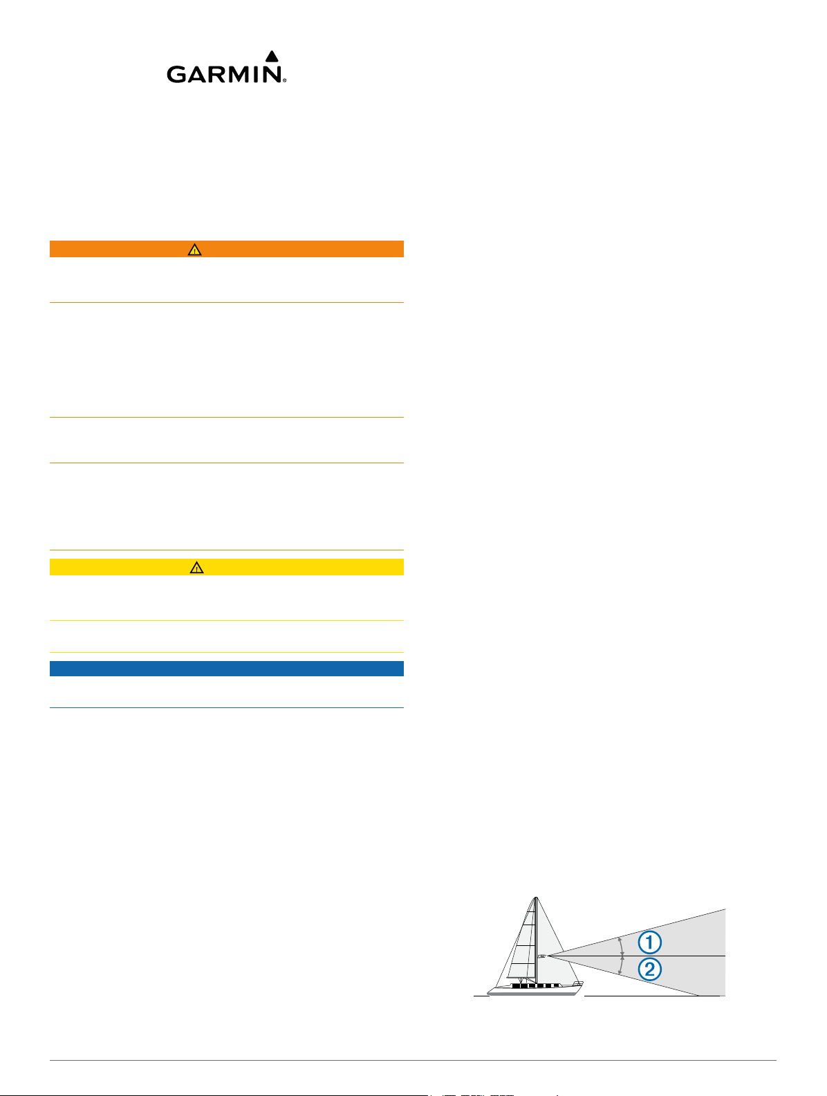
• Most radar beams spread vertically 12.5° above À and 12.5°
below Á the radome's radiating element. On vessels with
higher bow angles at cruise speed, the installation angle can
be lowered to point the beam slightly downward to the
waterline while at rest. Use shims if necessary.
Loading the New Software on a Memory Card
The device may contain a software-update memory card. If so,
follow the instructions provided with the card. If a software
update memory card is not included, you must copy the
software update to a memory card.
November 2013
190-01656-02_0B Printed in Taiwan
Page 2
• The radome has two mounting options when installed on a
standard marine mount. One mounting option is closer to the
center of the radome Â, and the second option is offset
towards the back à to move the radar further away from the
mast.
• The device should be mounted away from heat sources such
as smoke stacks and lights.
• The device should be mounted at a different level than
horizontal spreaders and mast crosstrees.
• To avoid interference with a magnetic compass, the device
should not be mounted closer to a compass than the
compass-safe distance value listed in the product
specifications.
• Other electronics and cables should be mounted more than
2 m (6 ½ ft.) from the radar beam path.
• GPS antennas should be either above or below the radar
beam path.
• The device should be mounted at least 1 m (40 in.) from any
transmitting equipment.
• The device should be mounted at least 1 m (40 in.) away
from cables carrying radio signals such as VHF radios,
cables, and antennas.
For Single Side Band (SSB) radios, increase the distance to
2 m (6 ½ ft.).
• The power cable should be installed as close to the battery
source as possible.
◦ If is necessary to extend the power cable, the appropriate
gauge of wire must be used as directed in these
instructions.
◦ Incorrectly extended runs of cable may cause the radar to
malfunction due to insufficient power transmission.
Mounting the Radar
Before you mount the radar, you must review the mounting
location considerations and select a mounting location.
NOTE: The supplied M8 x 1.25 x 60 threaded rods can be used
on mounting thicknesses of 5 to 30 mm (3/16 to 1 3/16 in.)
(recommended). For surfaces over 30 mm (1 3/16 in.), use
longer threaded rods.
If you are not installing the device on a pre-drilled Garmin-
1
compatible radar mount, use the included mounting template
to drill four 9.5 mm (3/8 in.) mounting holes.
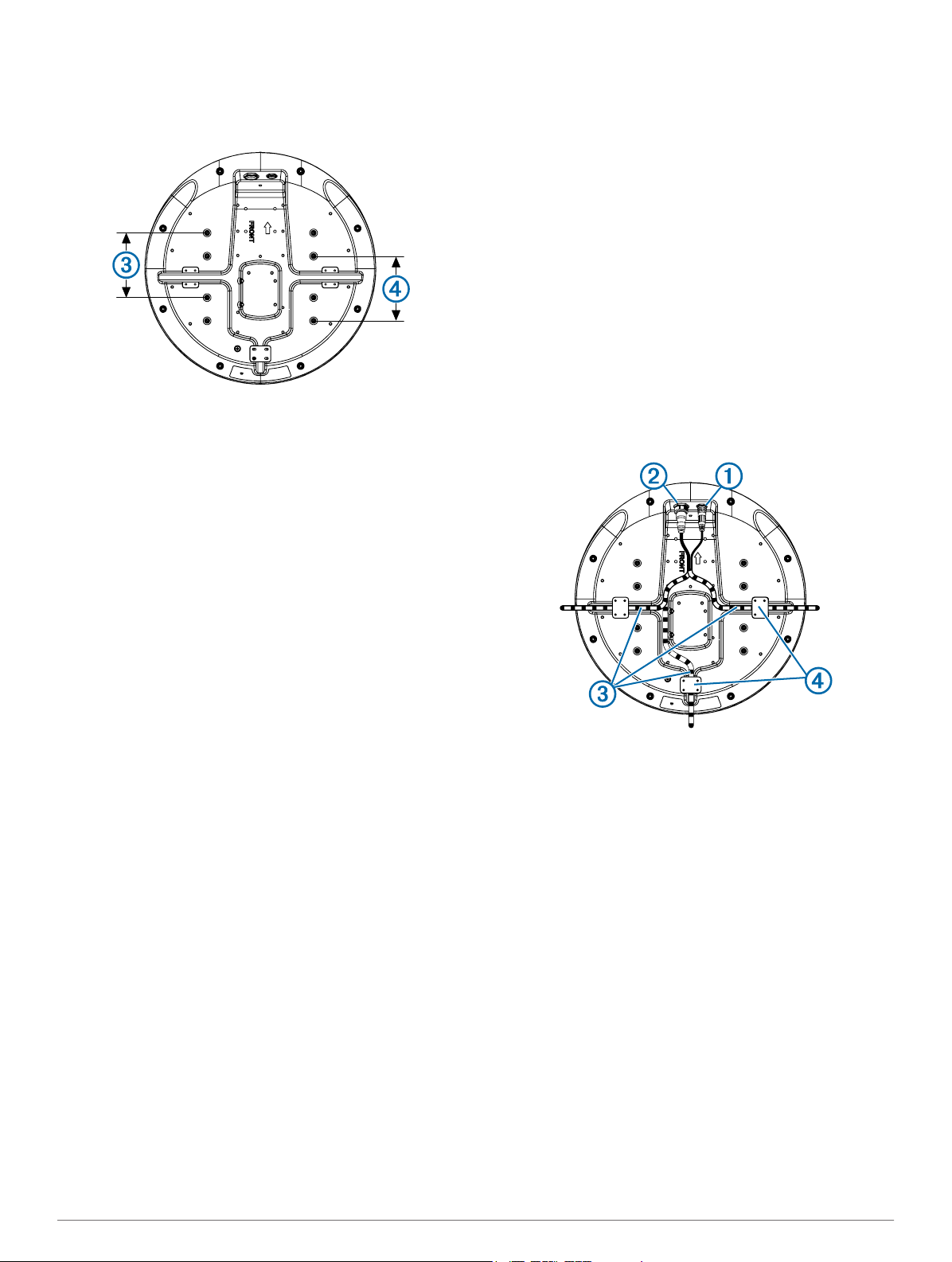
Install the locking ring and o-ring on the end of the Garmin
2
Marine Network cable.
Connect the power cable to the power port À and the
3
network cable to the network port Á.
Cable Considerations
It may be necessary to drill 31.7 mm (1 ¼ in.) holes for routing
the power or network cable. The provided rubber cable
grommet can be used to cover a cable installation hole.
• The grommet does NOT provide a waterproof seal. To make
the grommet waterproof, marine sealant must be applied.
• Additional cable grommets can be purchased from Garmin or
a Garmin dealer.
When installing the power and network cables, you should
observe these considerations.
• Cutting the Garmin Marine Network cable is not
recommended, but a field install kit can be purchased from
Garmin or a Garmin dealer if cutting the network cable is
necessary.
• To ensure safety, appropriate tie-wraps, fasteners, and
sealant should be used to secure the cable along the route
and through any bulkheads or the deck.
• Cables should not be run near moving objects and high-heat
sources or through doorways and bilges.
• To avoid interference with other equipment, power and
network cables should not be run next to or parallel to other
cables, such as radio antenna lines or power cables. If this is
not possible, the cables should be shielded with metal
conduit or a form of EMI shielding.
Press the cables into any of the guide grooves  on the
4
bottom of the case, and secure them using a cable holddown plate Ã.
The cables should be bent or twisted as little as possible.
Position the radome on the mounting surface with the
5
triangular mark on the case aligned to the front of the vessel.
Apply the included anti-seize compound to the threads of the
6
four M8 x 1.25 x 60 threaded rods.
Insert the four threaded rods into the mounting holes on the
7
bottom of the radome.
Up to 50 mm (2 in.) of the threaded rods may extend below
the radome.
Apply a bead of marine sealant on the mounting surface
8
around each mounting hole.
Fasten the radome Ä to the mounting surface Å using the
9
threaded rods Æ, flat washers Ç, spring washers È, and hex
nuts É.
2
Page 3

Using a torque wrench, tighten the nuts from 13.7 to 18.6 N-
10
m (10 to 14 lbf-in.) of force.
Connecting the Power Cable
WARNING
When connecting the power cable, do not remove the in-line
fuse holder. To prevent the possibility of injury or product
damage caused by fire or overheating, the appropriate fuse
must be in place as indicated in the product specifications. In
addition, connecting the power cable without the appropriate
fuse in place will void the product warranty.
Route the power cable from the device to the power source.
1
Connect the red wire to the positive (+) battery terminal, and
2
connect the black wire to the negative (-) battery terminal.
If you have not already done so, connect the power cable to
3
the device by turning the locking ring clockwise.
Power Cable Extensions
Connecting the power cable directly to the battery is
recommended. If it is necessary to extend the cable, the
appropriate gauge of wire must be used for the length of the
extension.
Distance Wire Gauge
2 m (6.5 ft.) 16 AWG (1.31 mm²)
4 m (13 ft.) 14 AWG (2.08 mm²)
6 m (19 ft.) 12 AWG (3.31 mm²)
Connecting to a Device or to the Marine Network
You can connect the radar either directly to a radar-compatible
Garmin device or to a Garmin Marine Network to share radar
information with all connected devices.
NOTE: Not all Garmin devices are compatible with the Garmin
Marine Network. See the installation instructions or owner's
manual provided with your device for more information.
Route the network cable to your compatible Garmin device.
1
If you have not already done so, install the locking rings and
2
o-rings on the end of the network cable.
Select an option:
3
• If the Garmin device is not compatible with the Garmin
Marine Network, connect the network cable to the port
labeled RADAR.
• If the device is compatible with the Garmin Marine
Network, connect the network cable to the port labeled
NETWORK.
Radar Operation
All functions of the Garmin radome are controlled with your
Garmin chartplotter. See the Radar section of your chartplotter's
manual for operating instructions. To download the latest
manual, go to www.garmin.com/support/.
Measuring the Potential Front-of-Boat Offset
The front-of-boat offset compensates for the physical location of
the radar scanner on a boat, if the radar scanner does not align
with the bow-stern axis.
Using a magnetic compass, take an optical bearing of a
1
stationary target located within viewable range.
Measure the target bearing on the radar.
2
If the bearing deviation is more than +/- 1°, set the front-of-
3
boat offset.
Setting the Front-of-Boat Offset
Before you can set the front-of-boat offset, you must measure
the potential front-of-boat offset.
The front-of-boat offset setting configured for use in one radar
mode is applied to every other radar mode and to the Radar
overlay.
Select Up or Down to adjust the offset.
Specifications
Specification Measurement
GMR 18 xHD weight 7.7 kg (16.95 lb.)
GMR 24 xHD weight 9.5 kg (20.9 lb.)
Temperature range -15 to 70°C (5 to 158°F)
Case material Thermoplastic resin
Default antenna rotation speed 48 RPM
Alternative antenna rotation speed 24 RPM
Power input source 10.5 to 35 Vdc, 3.5 A
Power output 4 kW peak
RF transmit frequency 9410 MHz nominal
Compass-safe distance 1 m (3.28 ft.)
GMR 18 xHD beam width 3.7°
GMR 24 xHD beam width 5.2°
Maximum range 48 nm
Minimum range 20 m (66 ft.)
Range discrimination 16 m (52.5 ft.)
Range scales 0.125, 0.25, 0.5, 0.75, 1, 1.5, 2, 3,
Detailed Dimensions
Item GMR 18 xHD GMR 24 xHD
Length 508.2 mm (20 in.) 645.4 mm (25 7/16 in.)
(width) 504.7 mm (19 7/8 in.) 642.5 mm (25 5/16 in.)
À
(height) 248.3 mm (9 ¾ in.) 250.3 mm (9 7/8 in.)
Á
4, 6, 8, 12, 16, 24, 36, 48 nm
3
Page 4

Item GMR 18 xHD GMR 24 xHD
0470
233 mm (9 3/16 in.) 233 mm (9 3/16 in.)
À
176.7 mm (6 15/16 in.) 245.4 mm (9 11/16 in.)
Á
141.5 mm (5 9/16 in.) 141.5 mm (5 9/16 in.)
Â
190 mm (7 ½ in.) 258.5 mm (10 3/16 in.)
Ã
139.2 mm (5 ½ in.) 207.7 mm (8 3/16 in.)
Ä
141.5 mm (5 9/16 in.) 141.5 mm (5 9/16 in.)
Å
227.5 mm (8 15/16 in.) 296.2 mm (9 11/16 in.)
Æ
Status LED Color and
Activity
Solid red The radar is getting ready for use.
Flashing green The radar is operating properly.
Flashing orange The radar software is being updated.
Flashing red The radar has encountered an error. Contact
Radar Status
Garmin product support for assistance.
Installation Troubleshooting
Symptom Possible Causes
The radar does
not power on (no
status LED).
The radar is not
available on the
Garmin device or
on devices
connected to the
Garmin Marine
Network.
The status LED is located on the product label, and can help
troubleshoot installation problems.
Garmin International, Inc.
1200 East 151st Street
Olathe, Kansas 66062, USA
Garmin (Europe) Ltd.
Liberty House, Hounsdown Business Park
Southampton, Hampshire, SO40 9LR UK
Garmin Corporation
No. 68, Zhangshu 2nd Road, Xizhi Dist.
New Taipei City, 221, Taiwan (R.O.C.)
• The power cable may not be connected correctly
to the device or to the battery. Check all
connections.
• The inline fuse may have blown. Check the fuse
and replace it if necessary.
• The wire gauge used to extend the power cable
may be too small for the length of the extension.
Check the table provided in the Power Cable
Extensions section of these instructions to make
sure the correct wire gauge is used.
• The device software may not be up-to-date.
Update the software on the device or on the
Garmin Marine Network.
• The network cable may not be connected
correctly to the device or to the Garmin Marine
Network. Check all connections.
• If a field-installable network connector was used,
it may have been installed improperly. Check the
connector.
Garmin® and the Garmin logo are trademarks of Garmin Ltd. or its subsidiaries, registered in the USA and other countries. GMR™ is a
trademarks of Garmin Ltd. or its subsidiaries. These trademarks may not be used without the express permission of Garmin.
© 2013 Garmin Ltd. or its subsidiaries www.garmin.com/support
 Loading...