

GPS 16/17 SERIES
TECHNICAL
SPECIFICATIONS
Garmin International, Inc.
1200 E. 151st Street
Olathe, KS 66062 USA
190-00228-21, Revision A
July 2005

© 2005 Garmin Ltd. or its subsidiaries
Garmin International, Inc.
1200 East 151
st
Street, Olathe, Kansas 66062, U.S.A.
Tel. 913/397.8200 or 800/800.1020
Fax 913/397.8282
Garmin (Europe) Ltd.
Unit 5, The Quadrangle, Abbey Park Industrial Estate, Romsey, SO51 9DL, U.K.
Tel. 44/0870.8501241
Fax 44/0870.8501251
Garmin Corporation
No. 68, Jangshu 2
nd
Road, Shijr, Taipei County, Taiwan
Tel. 886/2.2642.9199
Fax 886/2.2642.9099
All rights reserved. Except as expressly provided herein, no part of this manual may be reproduced, copied,
transmitted, disseminated, downloaded, or stored in any storage medium, for any purpose without the express prior
written consent of Garmin. Garmin hereby grants permission to download a single copy of this manual onto a hard
drive or other electronic storage medium to be viewed and to print one copy of this manual or of any revision hereto,
provided that such electronic or printed copy of this manual must contain the complete text of this cop yright notice
and provided further that any unauthorized commercial distribution of this manual or any revision hereto is strictly
prohibited.
Information in this document is subject to change without notice. Garmin reserves the right to change or improve its
products and to make changes in the content without obligation to notify any person or organization of such changes
or improvements. Visit the Garmin Web site (www.garmin.com) for current updates and supplemental information
concerning the use and operation of this and other Garmin produ cts.
Garmin®, AutoLocate®, and MapSource® are registered trademarks and WAAS Enabled™ is trademark of Garmin
Ltd. or its subsidiaries and may not be used without the express permission of Garmin.
Web site address: www.garmin.com
RECORD OF REVISIONS
Revision
Revision
Date
Description ECO #
A 7/8/05 Initial Release --
190-00228-21 GPS 16/17 Technical Specifications Rev. A
Page ii

TABLE OF CONTENTS
1 Introduction....................................................................................................1
1.1 Caution..............................................................................................................................................1
1.2 FCC Compliance...............................................................................................................................1
1.3 Limited Warranty..............................................................................................................................2
1.4 Overview...........................................................................................................................................3
1.5 Features.............................................................................................................................................3
1.6 GPS 16/17 Series...............................................................................................................................4
1.6.1 GPS 16LVS & 16HVS ..........................................................................................................4
1.6.2 GPS 17HVS...........................................................................................................................4
1.7 Technical Specifications....................................................................................................................5
1.7.1 Physical Characteristics.........................................................................................................5
1.7.1.1 Size..........................................................................................................................5
1.7.1.2 Weight.....................................................................................................................5
1.7.1.3 Cable........................................................................................................................5
1.7.1.4 Color........................................................................................................................5
1.7.1.5 Case Material...........................................................................................................5
1.7.1.6 GPS 17HVS Thread Specifications......................................................................... 5
1.7.2 Electrical Characteristics .......................................................................................................5
1.7.2.1 Input Voltage...........................................................................................................5
1.7.2.2 Input Current ...........................................................................................................5
1.7.2.3 Standby Current.......................................................................................................5
1.7.2.4 GPS Receiver Sensitivity.........................................................................................5
1.7.3 Environmental Characteristics...............................................................................................5
1.7.4 GPS Performance...................................................................................................................6
1.7.4.1 Receiver................................................................................................................... 6
1.7.4.2 Acquisition Times....................................................................................................6
1.7.4.3 Sentence Rate..........................................................................................................6
1.7.4.4 Accuracy..................................................................................................................6
1.7.5 Interfaces................................................................................................................................6
1.7.5.1 Port 1.......................................................................................................................6
1.7.5.2 Port 2.......................................................................................................................6
1.7.5.3 PPS..........................................................................................................................6
1.7.5.4 Power Control..........................................................................................................6
2 GPS 16/17 Wiring and Pinouts......................................................................7
2.1 GPS 16/17 Pinout..............................................................................................................................7
2.2 GPS 16/17 Wiring Diagrams.............................................................................................................8
3 Mechanical Characteristics & Mounting......................................................9
3.1 GPS 16 and GPS 17 Flush Mount.....................................................................................................9
3.2 GPS 17 ............................................................................................................................................10
3.3 GPS 16 Optional Magnetic Mount..................................................................................................11
4 Software Interface........................................................................................12
4.1 Received NMEA 0183 Sentences ...................................................................................................12
4.1.1 Almanac Information (ALM) ..............................................................................................12
4.1.2 Sensor Initialization Information (PGRMI).........................................................................13
4.1.3 Sensor Configuration Information (PGRMC)......................................................................13
4.1.4 Additional Sensor Configuration Information (PGRMC1)..................................................14
4.1.5 Output Sentence Enable/Disable (PGRMO)........................................................................14
4.1.6 Tune DGPS Beacon Receiver (PSLIB) ...............................................................................15
4.2 Transmitted NMEA 0183 Sentences...............................................................................................15
4.2.1 Sentence Transmission Rate................................................................................................15
190-00228-21 GPS 16/17 Technical Specifications Rev. A
Page iii

4.2.2 Transmitted Time.................................................................................................................16
4.2.3 Global Positioning System Almanac Data (ALM) ..............................................................16
4.2.4 Global Positioning System Fix Data (GGA)........................................................................16
4.2.5 GPS DOP and Active Satellites (GSA)................................................................................17
4.2.6 GPS Satellites in View (GSV).............................................................................................17
4.2.7 Recommended Minimum Specific GPS/TRANSIT Data (RMC) .......................................17
4.2.8 Track Made Good and Ground Speed (VTG)......................................................................17
4.2.9 Geographic Position (GLL) .................................................................................................18
4.2.10 Estimated Error Information (PGRME)...............................................................................18
4.2.11 GPS Fix Data Sentence (PGRMF).......................................................................................18
4.2.12 Map Datum (PGRMM)........................................................................................................18
4.2.13 Sensor Status Information (PGRMT)..................................................................................18
4.2.14 3D Velocity Information (PGRMV)....................................................................................19
4.2.15 DGPS Beacon Information (PGRMB).................................................................................19
4.3 Baud Rate Selection........................................................................................................................19
4.4 One-Pulse-Per-Second (PPS) Output.............................................................................................. 19
4.5 Received RTCM Data.....................................................................................................................19
Appendix A: Earth Datums...............................................................................20
Appendix B: Binary Phase Output Format......................................................23
Position Record...............................................................................................................................23
Receiver Measurement Record .......................................................................................................24
Sample C Code................................................................................................................................25
Appendix C: Ephemeris Data download (Programming Example)...............26
Synopsis .......................................................................................................................................... 26
Garmin Binary Format Review.......................................................................................................26
Ephemeris Download Procedure.....................................................................................................27
TX Packet: Ephemeris Data Request...................................................................................27
RX Packet: Acknowledgement............................................................................................ 27
RX Packet: Number of Data Packets to Expect...................................................................27
TX Packet: Acknowledgement............................................................................................27
RX Packet: Ephemeris Data.................................................................................................28
TX Packet: Download Complete.........................................................................................30
Appendix D: Sensor Configuration Software .................................................31
Downloading the Sensor Configuration Software...........................................................................31
Selecting a Model............................................................................................................................31
Connecting to the Sensor.................................................................................................................31
File Menu........................................................................................................................................32
Comm Menu....................................................................................................................................32
Config Menu ...................................................................................................................................32
View Menu......................................................................................................................................33
Help Menu.......................................................................................................................................33
LIST OF TABLES AND FIGURES
GPS 16LVS & 16HVS..................................................................................................................................................4
GPS17HVS with Pole Mount........................................................................................................................................4
GPS 17HVS Flush Mount .............................................................................................................................................4
Table 1: GPS 16/17 Wire Pinout...................................................................................................................................7
Figure 1: Computer Serial Port Interconnection............................................................................................................8
Figure 2: PDA Serial Port Interconnection....................................................................................................................8
Figure 3: Basic NMEA Device Interconnection............................................................................................................8
Figure 4: GPS 16 & GPS 17 Flush Mount Dimensions.................................................................................................9
Figure 5: GPS 17 Dimensions.....................................................................................................................................10
Figure 6: GPS 17 Attaching to the Included Pole Mount............................................................................................11
Figure 7: Optional GPS 16 Magnetic Mount...............................................................................................................11
Table 2: NMEA 0183 Output Sentence Order and Size..............................................................................................15
Table 3: Characters per Second for Available Baud Rates ........................................................................ ..................15
190-00228-21 GPS 16/17 Technical Specifications Rev. A
Page iv

1 INTRODUCTION
1.1 Caution
The GPS system is operated by the government of the United States, which is solely responsible for its accuracy and
maintenance. Although the GPS 16/17 is a precision electronic NAVigation AID (NAVAID), any NAVAID can be
misused or misinterpreted, and therefore become unsafe. Use these products at your own risk. To reduce the risk,
carefully review and understand all aspects of these Technical Specifications before using the GPS 16/17. When in
actual use, carefully compare indications from the GPS to all available navigation sources including the information
from other NAVAIDs, visual sightings, charts, etc. For safety, always resolve any discrepancies before continuing
navigation.
1.2 FCC Compliance
The GPS 16/17 complies with Part 15 of the FCC interference limits for Class B digital devices FOR HOME OR
OFFICE USE. These limits are designed to provide reasonable protection against harmful interference in a
residential installation, and are more stringent than “outdoor” requirements.
Operation of this device is subject to the following conditions: (1) This device may not cause harmful interference,
and (2) this device must accept any interference received, including interference that may cause undesired operation.
This equipment generates, uses and can radiate radio frequency energy and, if not installed and used in accordance
with the instructions, may cause harmful interference to radio communications. However, there is no guarantee that
interference will not occur in a particular installation. If this equipment does cause harmful interference to radio or
television reception, which can be determined by turning the equipment off and on, the user is encouraged to try to
correct the interference by one or more of the following measures:
• Reorient or relocate the receiving antenna.
• Increase the separation between the equipment and receiver.
• Connect the equipment into an outlet on a circuit different from that to which the receiver is connected.
• Consult the dealer or an experienced radio/TV technician for help.
The GPS 16/17 does not contain any user-serviceable parts. Unauthorized repairs or modifications could result in
permanent damage to the equipment, and void your warranty and your authority to operate this device under Part 15
regulations.
190-00228-21 GPS 16/17 Technical Specifications Rev. A
Page 1

1.3 Limited Warranty
This Garmin product is warranted to be free from defects in materials or workmanship for one year from the date of
purchase. Within this period, Garmin will at its sole option repair or replace any components that fail in normal use.
Such repairs or replacement will be made at no charge to the customer for parts or labor, provided that the customer
shall be responsible for any transportation cost. This warranty does not cover failures due to abuse, misuse, accident,
or unauthorized alteration or repairs.
THE WARRANTIES AND REMEDIES CONTAINED HEREIN ARE EXCLUSIVE AND IN LIEU OF ALL
OTHER WARRANTIES EXPRESS OR IMPLIED OR STATUTORY, INCLUDING ANY LIABILITY ARISING
UNDER ANY WARRANTY OF MERCHANTABILITY OR FITNESS FOR A PARTICULAR PURPOSE,
STATUTORY OR OTHERWISE. THIS WARRANTY GIVES YOU SPECIF IC LEG AL RIG HTS , WH ICH MAY
VARY FROM STATE TO STATE.
IN NO EVENT SHALL GARMIN BE LIABLE FOR ANY INCIDENTAL, SPECIAL, INDIRECT OR
CONSEQUENTIAL DAMAGES, WHETHER RESULTING FROM THE USE, MISUSE, OR INABILITY TO
USE THIS PRODUCT OR FROM DEFECTS IN THE PRODUCT. Some states do not allow the exclusion of
incidental or consequential damages, so the above limitations may not apply to you.
Garmin retains the exclusive right to repair or replace the unit or software or offer a full refund of the purchase price
at its sole discretion. SUCH REMEDY SHALL BE YOUR SOLE AND EXCLUSIVE REMEDY FOR ANY
BREACH OF WARRANTY.
To obtain warranty service, contact your local Garmin authorized dealer or call Garmin Product Support at one of
the numbers listed below for shipping instructions and an RMA tracking number. The unit should be securely
packed with the tracking number clearly written on the outside of the package. The unit should then be sent, freight
charges prepaid, to any Garmin warranty service station. A copy of the original sales receipt is required as the proof
of purchase for warranty repairs.
Garmin International, Inc.
1200 E 151st Street, Olathe, Kansas 66062 U.S.A.
Tel. 913/397.8200 or 800/800.1020
Fax. 913/397.8282
Garmin (Europe) Ltd.
Unit 5, The Quadrangle, Abbey Park Industrial Estate, Romsey, SO51 9DL U.K.
Tel. 44/0870.8501241
Fax 44/0870.8501251
Online Auction Purchases: Products sold through online auctions are not eligible for rebates or other special offers
from Garmin. Online auction confirmations are not accepted for warranty verification. To obtain warranty service,
an original or copy of the sales receipt from the original retailer is required. Garmin will not replace missing
components from any package purchased through an online auction.
International Purchases: A separate warranty is provided by international distributors for units purchased outside
the United States. This warranty is provided by the local in-country distributor and this distributor provides local
service for your unit. Distributor warranties are only valid in the area of intended distribution. Units purchased in the
United States or Canada must be returned to the Garmin service center in the United Kingdom, the United States,
Canada, or Taiwan for service.
190-00228-21 GPS 16/17 Technical Specifications Rev. A
Page 2

1.4 Overview
The GPS 16/17 series products are complete GPS sensors including embedded receiver and antenna, designed for a
broad spectrum of OEM (Original Equipment Manufacture) system applications. Based on the proven technology
found in other Garmin 12-channel GPS receivers, the GPS 16/17 tracks up to 12 satellites at a time while providing
fast time-to-first-fix, one-second navigation updates, and low power consumption. This generation of GPS sensors
adds the capability of FAA Wide Area Augmentation System (WAAS) differential GPS. The GPS 16/17’s farreaching capability meets the sensitivity requirements of land navigation as well as the dynamics requirements of
high-performance aircraft.
The GPS 16/17 design uses the latest technology and high-level circuit integration to achieve superior performance
while minimizing space and power requirements. All critical components of the system including the RF/IF receiver
hardware and the digital baseband are designed and manufactured by Garmin to ensure the quality and capability of
the GPS. The hardware capability combined with software intelligence makes the GPS 16/17 easy to integrate and
use.
The GPS 16/17 series products are designed to withstand rugged operating conditions and are waterproof to IEC
60529 IPX7, immersion in 1 meter of water for 30 minutes. These complete GPS receivers require minimal
additional components to be supplied by an OEM or system integrator. A minimum system must provide the GPS
with a source of power and a clear view of the GPS satellites. The system may communicate with the GPS via two
full-duplex communication channels. Internal FLASH memory allows the GPS to retain critical data such as satellite
orbital parameters, last-known position, date, and time. End user interfaces such as keyboards and displays are the
responsibility of the application designer.
1.5 Features
• 12-channel GPS receiver tracks and uses up to 12 satellites for fast, accurate positioning and low power
consumption.
• Differential DGPS capability using real-time WAAS or RTCM corrections yielding 3 to 5 meter position
accuracy (see Section 1.7 Technical Specifications).
• Compact, rugged design ideal for applications with minimal space.
• May be remotely mounted in an out-of-the-way location.
• Receiver position information can be displayed directly on a chartplotter or PC.
• User initialization is not required. Once the unit is installed and has established a location fix, the unit
automatically produces navigation data.
• User-configurable navigation mode (2-dimensional or 3-dimensional fix).
• Highly accurate one-pulse-per-second (PPS) output for precise timing measurements. Pulse width is
configurable in 20 millisecond increments from 20 ms to 980 ms with 1 µs accuracy.
• Configurable for binary format carrier phase data output on COM 1 port.
• Flexible input voltage levels of 3.3 VDC to 6.0 VDC with over-voltage protection in the GPS 16LVS, and
8.0 VDC to 40 VDC in the GPS 16HVS and GPS 17HVS.
• FLASH-based program and non-volatile memory. New software revisions available through Web site
download. Non-volatile memory does not require battery backup.
• Waterproof design allows continuous exposure to the prevailing weather conditions at most locations.
• GPS 17HVS can be flush mounted or pole mounted on the enclosed 1” marine mast mount.
190-00228-21 GPS 16/17 Technical Specifications Rev. A
Page 3
1.6 GPS 16/17 Series
There are several different products in the GPS 16/17 product series, as described below.
1.6.1 GPS 16LVS & 16HVS
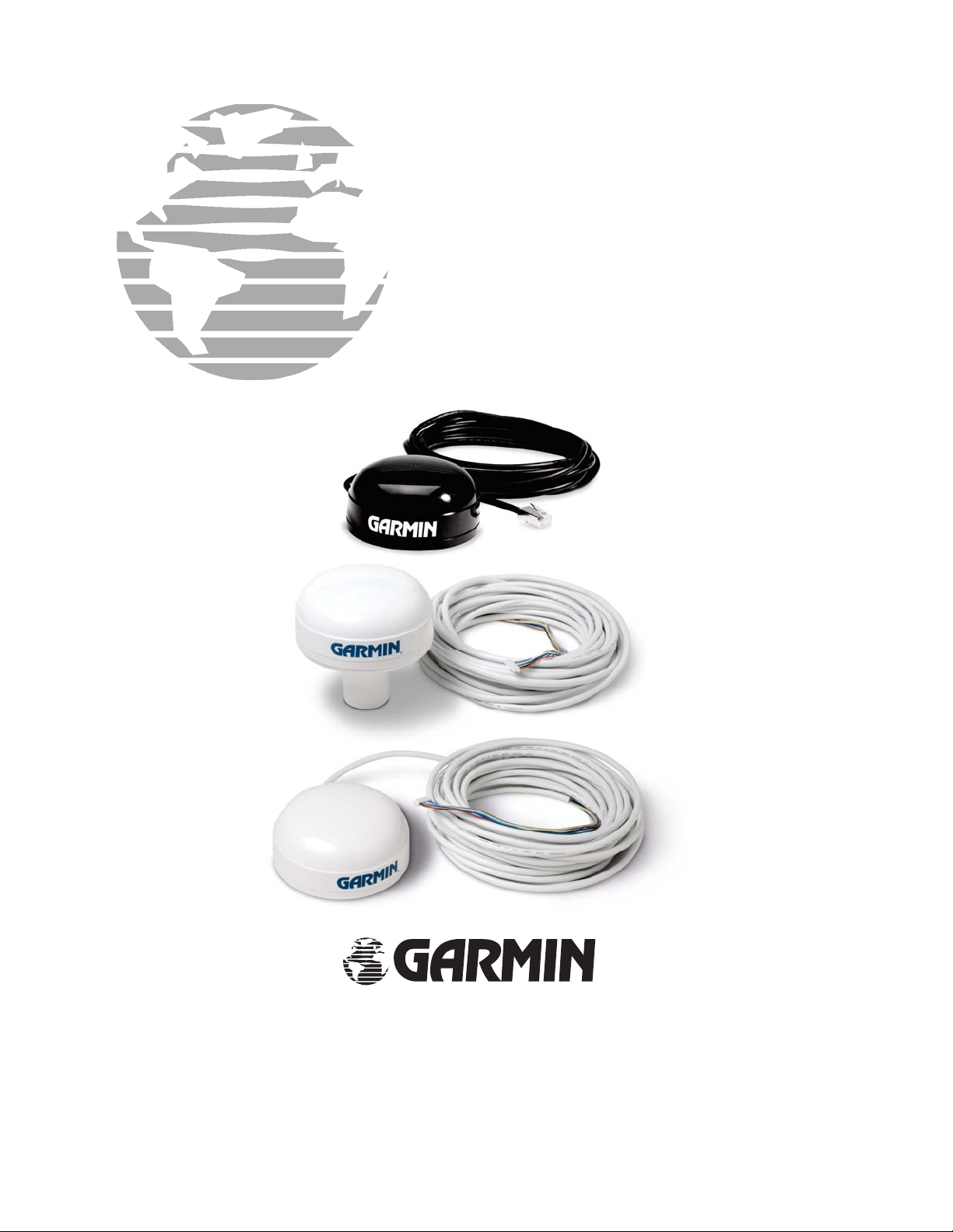
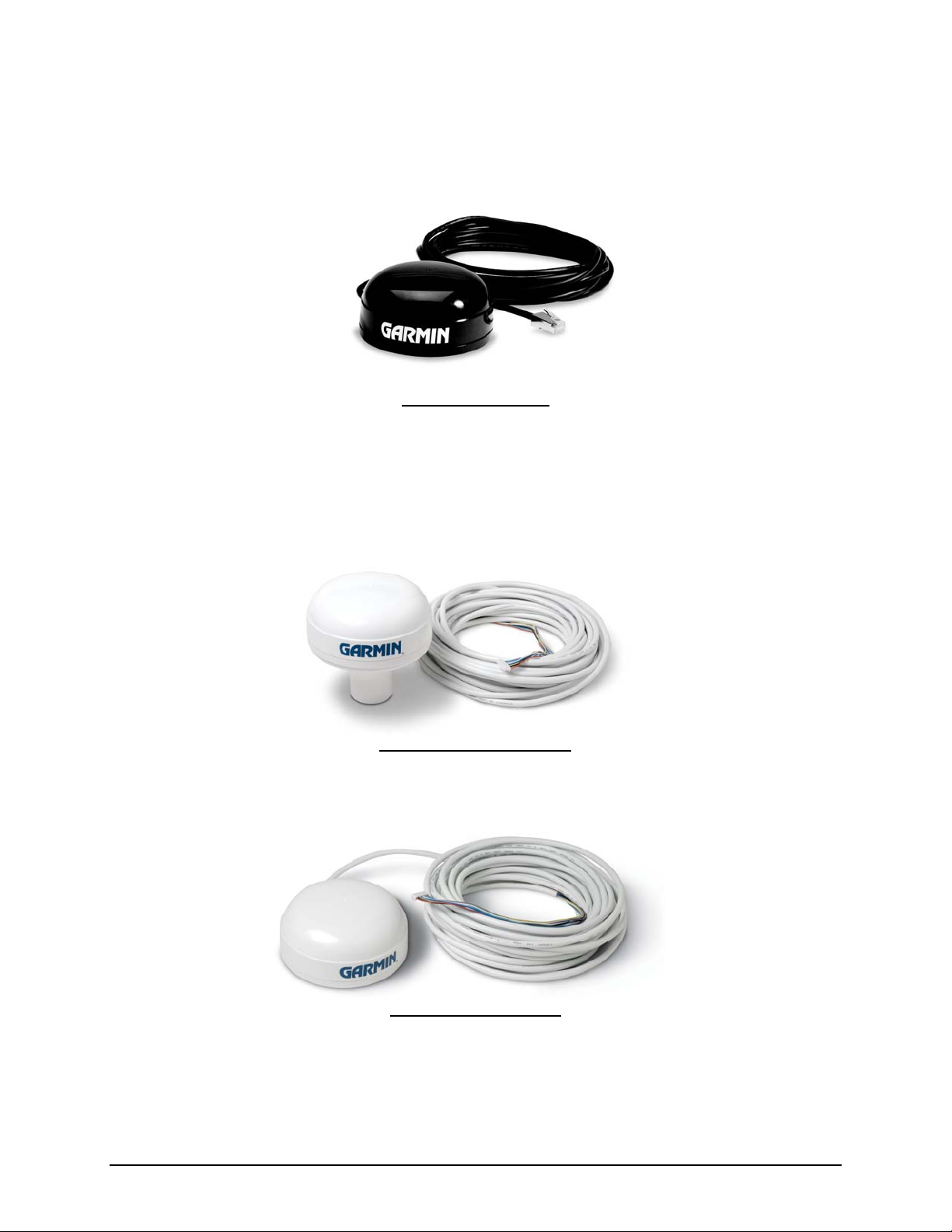
Both the GPS 16LVS and GPS 16HVS are black with a white logo.
GPS 16LVS & 16HVS
1.6.2 GPS 17HVS
The GPS 17HVS is white with a blue logo. GPS 17HVS can be flush mounted or pole mounted on the enclosed 1”
pole mount (also called a marine mount). You can also use the GPS17HVS on a standard one-inch, 14 threads-perinch marine mount.
GPS17HVS with Pole Mount
GPS 17HVS Flush Mount
190-00228-21 GPS 16/17 Technical Specifications Rev. A
Page 4

1.7 Technical Specifications
Specifications are subject to change without notice.
1.7.1 Physical Characteristics
1.7.1.1 Size
• GPS 16: 3.58” (91.0 mm) diameter, 1.65” (42 mm) high
• GPS 17: 3.58” (91.0 mm) diameter, 3.60” (91.5 mm) high
1.7.1.2 Weight
• GPS 16LVS & 16HVS only: 6.4 oz (181 g)
• GPS 16LVS & 16HVS with 5-meter cable: 11.7 oz (3 32 g)
• GPS 16LVS & 16HVS cable alone: 5.3 oz (151 g)
• GPS 17HVS only: 7.1 oz (201 g)
• GPS 17HVS with 30-foot cable: 16.8 oz (465 g)
• GPS 17HVS with pole mount adapter & cable: 18.2 oz (516 g)
• GPS 17HVS pole mount adapter alone: 1.4 oz (40 g)
• GPS 17HVS cable alone: 9.7 oz (275 g)
1.7.1.3 Cable
• GPS 16LVS & 16HVS: Black PVC-jacketed, 5-meter, foil-shielded, 8-conduct or 2 8 A WG wi th RJ -45 te rmination
• GPS 17HVS: White PVC-jacketed, 30-foot, foil-shielded, 8-conductor 28 AWG with JST connector termination
1.7.1.4 Color
• GPS 16LVS & 16HVS: Black with white logos
• GPS 17HVS: White with blue logos
1.7.1.5 Case Material
Polycarbonate thermoplastic that is waterproof to IEC 60529 IPX7 level (immersion in 1 meter of water for 30
minutes).
1.7.1.6 GPS 17HVS Thread Specifications
Standard one-inch, 14 threads-per-inch
1.7.2 Electrical Characteristics
1.7.2.1 Input Voltage
• GPS 16LVS: 3.3 VDC to 6.0 VDC regulated, <100 mV ripple
• GPS 16HVS & 17HVS: 8.0 VDC to 40 VDC unregulated
1.7.2.2 Input Current
• GPS 16HVS, GPS 17HVS 60 mA @ 8 VDC
40 mA @ 12 VDC
15 mA @ 40 VDC
• GPS 16LVS: 65 mA typical
1.7.2.3 Standby Current
<1mA for all GPS 16 and GPS 17 models
1.7.2.4 GPS Receiver Sensitivity
-165 dBW minimum
1.7.3 Environmental Characteristics
• Operating Temperature: -30°C to +80°C
• Storage Temperature: -40°C to +80°C
190-00228-21 GPS 16/17 Technical Specifications Rev. A
Page 5

1.7.4 GPS Performance
1.7.4.1 Receiver
WAAS Enabled™; 12 parallel channel GPS receiver continuously tracks and uses up to 12 satellites (up to 11 with
PPS active) to compute and update your position.
1.7.4.2 Acquisition Times
• Reacquisition: Less than 2 seconds
• Warm: Approx. 15 seconds (all data known)
• Cold: Approx. 45 seconds (initial position, time, and almanac known; ephemeris unknown)
• AutoLocate®: 5 minutes (almanac known; initial position and time unknown)
• SkySearch: 5 minutes (no data known)
1.7.4.3 Sentence Rate
1 second default; NMEA 0183 output interval configurable from 1 to 900 seconds in 1-second increments
1.7.4.4 Accuracy
• GPS Standard Positioning Service (SPS)
Position: <15 meters, 95% typical (100 meters with Selective Availability on)
Velocity: 0.1 knot RMS steady state
• DGPS (USCG/RTCM)
Position: 3–5 meters, 95% typical
Velocity: 0.1 knot RMS steady state
• DGPS (WAAS)
Position: <3 meters, 95% typical
Velocity: 0.1 knot RMS steady state
• PPS Time: ±1 microsecond at rising edge of PPS pulse (subject to Selective Availability)
• Dynamics: 999 knots velocity (only limited at altitude greater than 60,000 feet), 6g dynamics
1.7.5 Interfaces
• True RS-232 output, asynchronous serial input compatible with RS-232 or TTL voltage levels, RS-232 polarity.
• User selectable baud rate: 300, 600, 1200, 2400, 4800, 9600, 19200, or 38400.
1.7.5.1 Port 1
• Configurable between NMEA 0183 Ve rsi o ns 2.00 and 3.00
• ASCII output sentences GPALM, GPGGA, GPGLL, GPGSA, GP GS V, GPRM C, GPVTG (NMEA-approved
sentences); PGRMB, PGRME, PGRMF, PGRMM, PGRMT, and PGRMV (Garmin proprietary sentences)
• NMEA 0183 Outputs (see Section 4.2 Transmitted NMEA 0183 Sentences for full protocol specifications)
Position, velocity, and time
Receiver and satellite status
Differential Reference Station ID and RTCM Data age
Geometry and error estimates
• NMEA 0183 Inputs (see Section 4.1 Received NMEA 0183 Sentences for full protocol specifications)
Initial position, date, and time (not required)
Earth datum and differential mode configuration command, PPS Enable, GPS satellite almanac
• Configurable for binary data output including GPS carrier phase data
1.7.5.2 Port 2
Real-time Differential Correction input (RTCM SC-104 message types 1, 2, 3, 7, and 9)
1.7.5.3 PPS
1 Hz pulse, programmable width, 1 µs accuracy
1.7.5.4 Power Control
• Off: Open circuit
• On: Ground, or pull to low logic level <0.3 volts
190-00228-21 GPS 16/17 Technical Specifications Rev. A
Page 6

2 GPS 16/17 WIRING AND PINOUTS
2.1 GPS 16/17 Pinout
The GPS 16LVS and GPS 16HVS sensors utilize an 8-pin RJ-45 plug. The GPS 17HVS terminates in a JST
connector, which is mainly for factory testing; you can remove the JST connector without voiding your warranty.
The following is a functional description of each wire in the cable assembly.
RJ-45
Pin
#
Wire
Color
Signal
Name
Description
1 Red POWER GPS 16LVS: Regulated +3.3 to +6 VDC. Typical operating current is 80 mA. An
internal 6.8 V transient zener diode and a positive temperature coefficient
thermistor protect from transients and over-voltages. With voltages greater than
6.8 VDC the zener will draw several amps of current through the thermistor,
causing it to heat rapidly and eventually power the unit off, unless an external
fuse blows first. When proper supply voltages are returned, the thermistor will
cool and allow the GPS 16LVS to operate.
GPS 16HVS & GPS 17HVS: Vin can be an unregulated 8.0 VDC to 40 VDC,
optimized for 12 VDC. Typical operating power is 800 mW. This voltag e drives a
switching regulator with a nominal 5.0 VDC output, which powers an internal
linear regulator, producing the system Vcc.
2 Black GROUND Power and Signal Ground
3 Yellow REMOTE
POWER
ON/OFF
External Power Control Input. Active (ON) if less than 0.3 VDC. Inactive (OFF)
if open-circuit. Pulling this pin to ground enables the unit; leaving the pin open-
circuited powers the internal regulators off and drops the supply current to less
than 1 mA. This input is intended to be driven by an open-collector output.
4 Blue PORT 1
DATA IN
First Serial Asynchronous Input. RS-232 compatible with maximum input
voltage range -25 < V < 25. This input may also be directly connected to standard
3 to 5 VDC CMOS logic. The low signal voltage requirement is <0.6 V, and the
high signal voltage requirement is >2.4 V. Input impedance is between 3.0 and
7.0 kΩ. This input may be used to receive serial initialization/ configuration data
5 White PORT 1
DATA
OUT
as specified in Section 4.1
First Serial Asynchronous Output. This RS-232 compatible output normally
provides serial data which is formatted per NMEA 0183, Version 3.0. This output
is also capable of outputting phase data information; see Appendix C for details.
Received NMEA 0183 Sentences.
The NMEA 0183 baud rate is switchable in the range of 300 to 38400 baud. The
default baud rate is 4800.
6 Gray PPS One-Pulse-Per-Second Output. Typical voltage rise and fall times are 300 ns.
Impedance is 150 Ω. Open circuit output voltage is low = 0 V and high = Vin in
the GPS 16LVS, and low = 0 V and high = 5.0 V in the GPS 16HVS and GPS
17HVS. The default format is a 100 ms wide active-high pulse at a 1 Hz rate; the
pulse width is configurable in 20 ms increments. Rising edge is synchronized to
the start of each GPS second. This output provides between 800 mVp-p to
1.7 Vp-p for GPS 16LVS and 1.4 Vp-p for the GPS 16HVS and 17HVS into a
50 Ω load. The pulse time measured at the 50% voltage point will be about 50 ns
earlier with a 50 Ω load than with no l oad.
7 Green PORT 2
DATA IN
Second Serial Asynchronous Input, electrically identical to PORT 1 DATA IN.
This input may be used to receive serial differential GPS data formatted per
RTCM SC-104 Recommended Standards For Differential Navstar GPS Service,
8 Violet PORT 2
DATA
Version 2.2 (see Section 4.5
Second Serial Asynchronous Output, electrically identical to PORT 1 DATA
OUT. Reserved for future use.
Received RTCM Data for details).
OUT
Table 1: GPS 16/17 Wire Pinout
190-00228-21 GPS 16/17 Technical Specifications Rev. A
Page 7
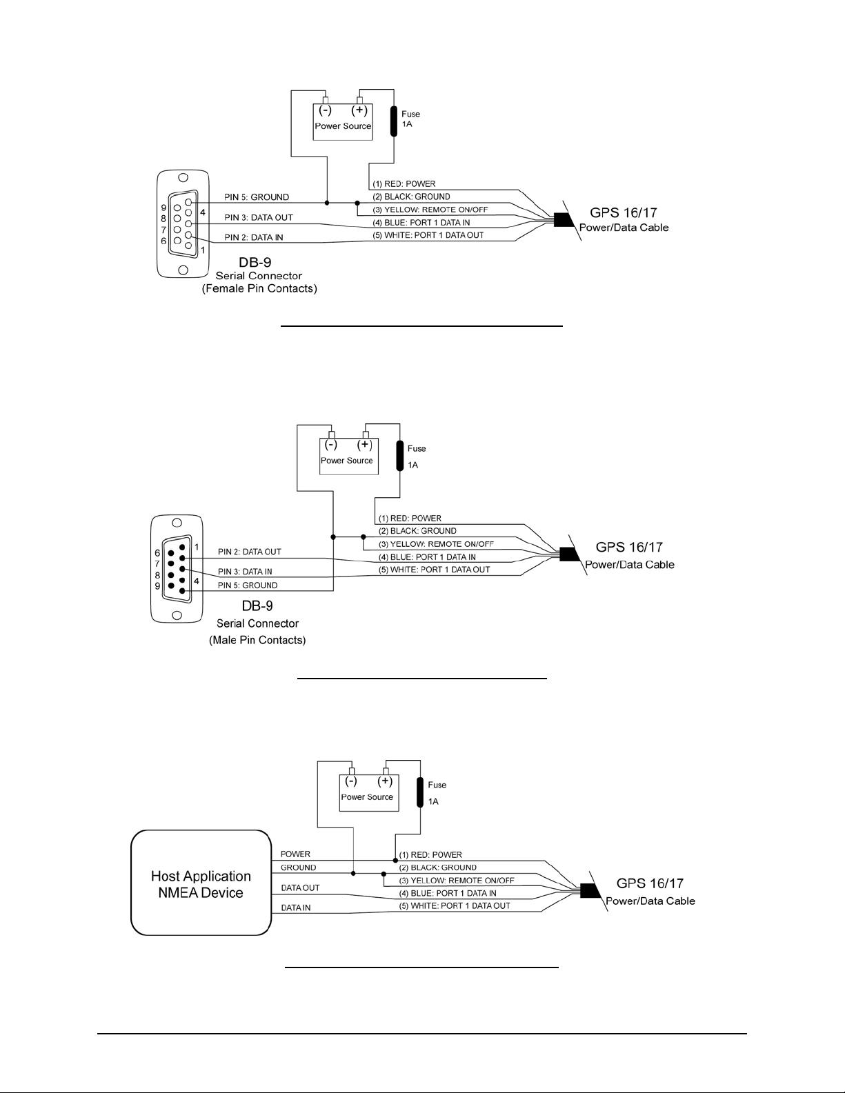
2.2 GPS 16/17 Wiring Diagrams
Figure 1: Computer Serial Port Interconnection
Figure 2: PDA Serial Port Interconnection
Figure 3: Basic NMEA Device Interconnection
190-00228-21 GPS 16/17 Technical Specifications Rev. A
Page 8
 Loading...