

Page 1
®
Apollo™ RA770 Installation
DRAFT
Instructions
Important Safety Information
WARNING
Failure to follow these warnings and cautions could result in
personal injury, damage to the vessel, or poor product
performance.
See the
product box for product warnings and other important
information.
This device must be installed according to these instructions.
Disconnect the vessel's power supply before beginning to install
this product.
Before applying power to this product, make sure it has been
correctly grounded, following the instructions in the guide.
Always wear safety goggles, ear protection, and a dust mask
when drilling, cutting, or sanding.
When drilling or cutting, always check what is on the opposite
side of the surface.
You must read all installation instructions before beginning the
installation. If you experience difficulty during the installation,
contact FUSION® Product Support.
What's In the Box
• Mounting gasket
• Four 8-gauge, self-tapping screws
• Two screw covers
• Power and speaker wiring harness
• Auxiliary-in, line-out, and subwoofer-out wiring harnesses
• 2 m (6 ft.) NMEA 2000® drop cable
• Dust cover
Tools Needed
• Phillips screwdriver
• Electric drill
• Drill bit (size varies based on surface material and screws
• Rotary cutting tool or jigsaw
• Silicone-based marine sealant (optional)
Mounting Considerations
• The stereo must be mounted on a flat surface.
• The stereo must be mounted in a location that allows open
• If you are installing the stereo in a location that may be
Important Safety and Product Information guide in the
CAUTION
NOTICE
used)
airflow around the rear of the stereo for heat ventilation.
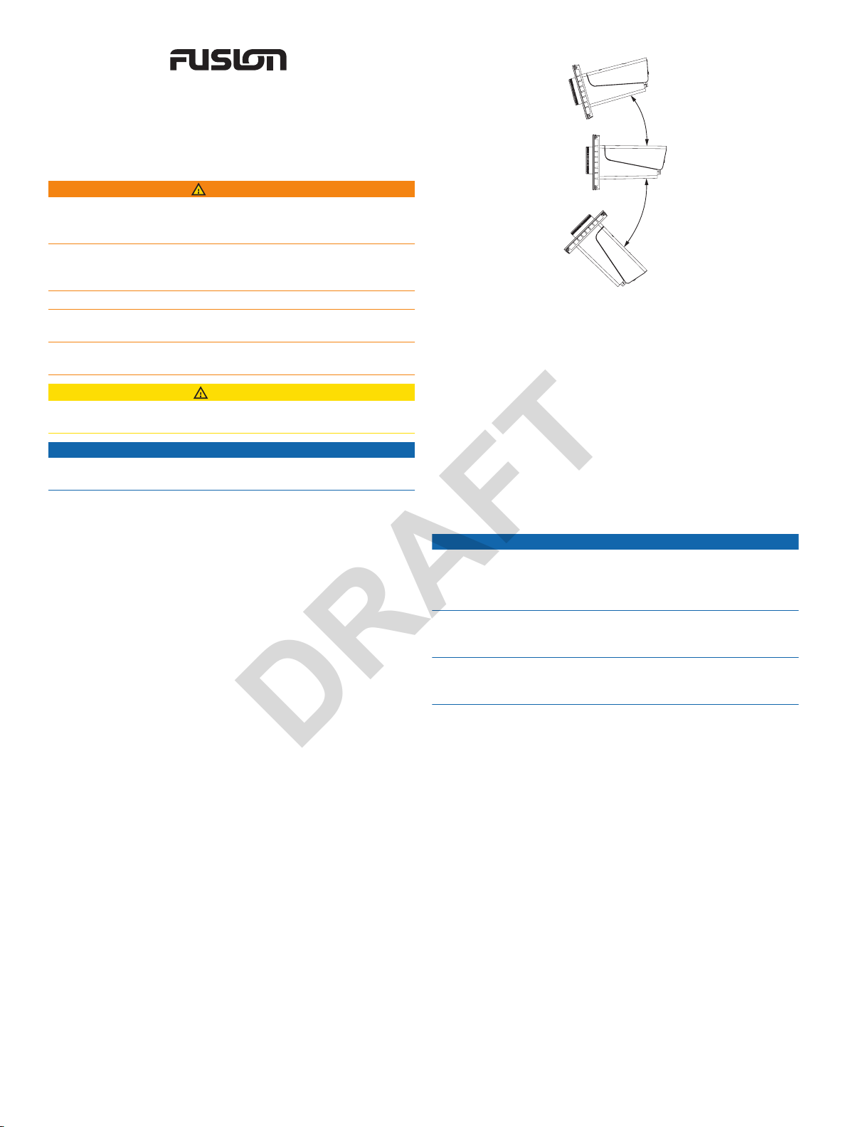
exposed to water, it must be mounted within 45 degrees
below or 15 degrees above the horizontal plane.
• If you are installing the stereo in a location that may be
exposed to water, you should install any connected cables
with a drip loop to allow water to drip down off the cable and
avoid damage to the stereo.
• If you need to mount the stereo outside a boat, it must be
mounted in a location far above the waterline, where it is not
submerged.
• If you need to mount the stereo outside a boat, it should be
mounted in a location where it cannot be damaged by docks,
pilings, or other pieces of equipment.
• To avoid interference with a magnetic compass, the stereo
should be installed at least 15 cm (5.9 in.)
compass.
Mounting the Stereo
NOTICE
Be careful when cutting the hole to mount the stereo. There is
only a small amount of clearance between the case and the
mounting holes, and cutting the hole too large could
compromise the stability of the stereo after it is mounted.
Be careful when installing the stereo in an aluminum boat or a
boat with a conductive hull, if you require the electrical system to
be isolated from the boat hull.
Do not apply grease or lubricant to the screws when fastening
the stereo to the mounting surface. Grease or other lubricants
can cause damage to the stereo housing.
Before you can mount the stereo in a new location on the
mounting surface, you must select a location in accordance with
the mounting considerations.
Trim the template and make sure it fits at the mounting
1
location.
Adhere the template to the mounting surface.
2
Using a drill bit appropriate for the mounting surface, drill a
3
hole inside the corner of the dashed line on the template to
prepare the mounting surface for cutting.
Using a rotary-cutting tool, cut the mounting surface along
4
the inside of the dashed line on the template.
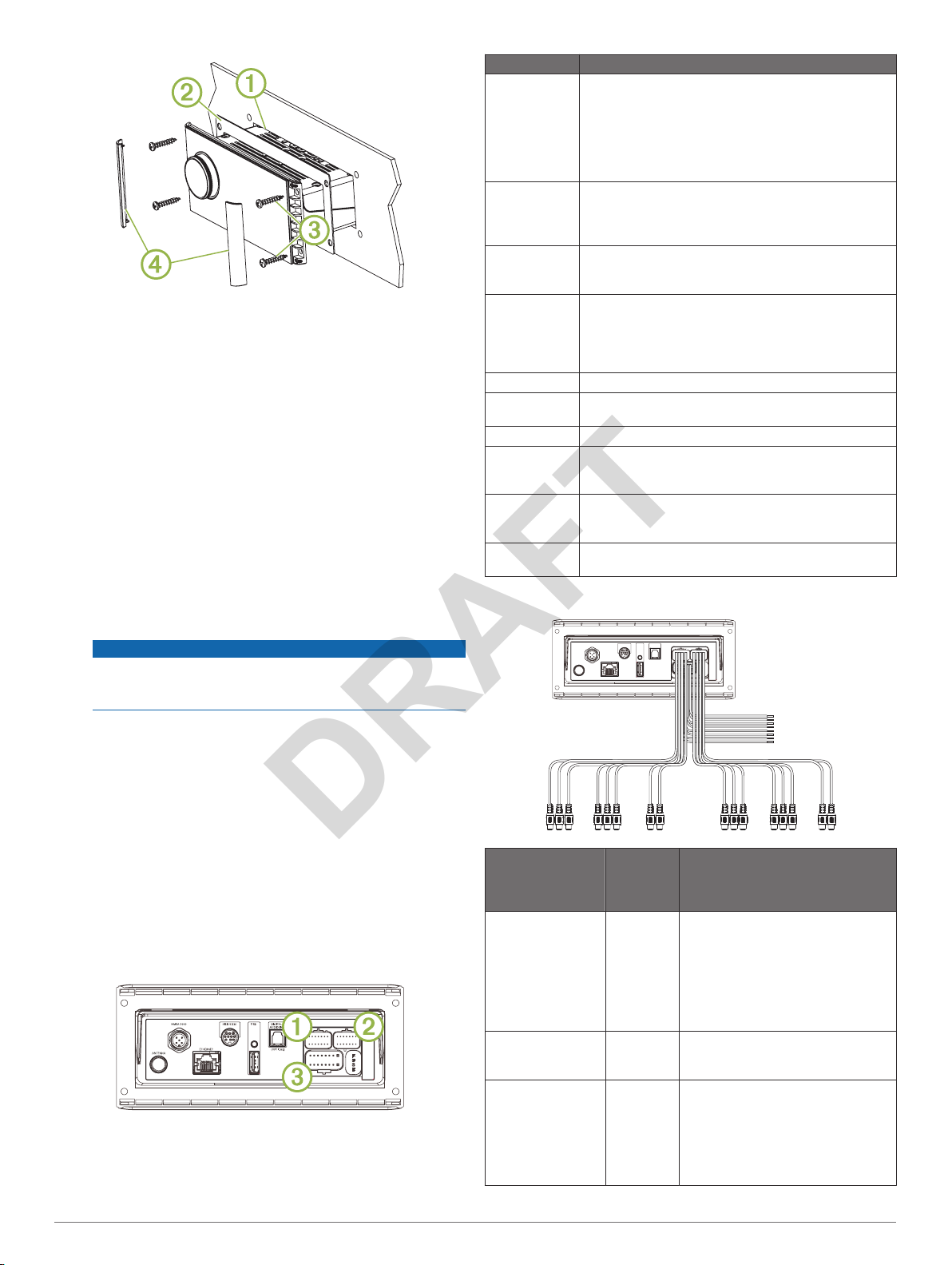
Place the stereo in the cutout À to test the fit.
5
away from a
April 2018
190-02382-02_0A
Page 2
If necessary, use a file and sandpaper to refine the size of
DRAFT
6
the cutout.
After the stereo fits correctly in the cutout, ensure the
7
mounting holes on the stereo line up with the pilot holes on
the template.
If the mounting holes on the stereo do not line up, mark the
8
new pilot-hole locations.
Using an appropriately sized drill bit for the mounting surface
9
and screw type, drill the pilot holes.
Remove the template from the mounting surface.
10
Make the necessary wiring connections (Connection
11
Considerations,
Select an option:
12
• If you are installing the stereo in a dry location, place the
included mounting gasket Á on the back of the stereo.
• If you are installing the stereo in a location that is exposed
to water, apply silicone-based marine sealant on the
mounting surface around the cutout.
Do not install the included mounting gasket if you applied
sealant to the mounting surface. Using sealant and the
mounting gasket may reduce water resistance.
Place the stereo into the cutout.
13
Secure the stereo to the mounting surface using the included
14
screws Â.
You should hand-tighten the screws when securing the
stereo to the mounting surface to avoid overtightening them.
Snap the screw covers in place Ã.
15
page 2).
NOTICE
Item Description
ANTENNA Connects the stereo to a typical AM/FM antenna.
If you are installing the stereo on a boat with a metal
hull, you must use a ground-dependent antenna. If you
are installing the stereo on a boat with a non-metal
hull, you must use a ground-independent antenna.
See the installation instructions provided with your
antenna for more information.
NMEA 2000 Connects the stereo to a
ETHERNET Connects the stereo to another FUSION PartyBus
SIRIUS XM Connects the stereo to a
USB Connects the stereo to a USB source.
DIGITAL
AUDIO IN
FUSE Contains the 15 A fuse for the device.
À
Á
Â
2000 System Wiring Diagram, page 4)
Connects to an NRX series remote control directly
Configuring an Optional Wired Remote,
(
stereo, zone stereo, or network (FUSION PartyBus
Networking,
receive SiriusXM stations where available (not
included).
Connects to a FUSION DAB module to receive DAB
stations where available (not included).
Connects the stereo to an optical digital audio source,
such as TV or DVD player.
Connects the stereo to the wiring harness for auxiliary
input 2, and for the line and subwoofer outputs for
zones 3 and 4.
Connects the stereo to the wiring harness for auxiliary
input 1, and for the line and subwoofer outputs for
zones 1 and 2.
Connects the stereo to the power and speaker wiring
harness.
page 4).
NMEA 2000 network (
SiriusXM
.
page 4).
®
Connect Tuner to
Wiring Harness Wire and Connector Identification
NMEA
Connection Considerations
For the stereo to function correctly, you must connect it to
power, to speakers, and to input sources. You should carefully
plan the layout of the stereo, speakers, input sources, optional
NMEA 2000
or network before making any connections.
Port Identification
2 Apollo RA770
network, and optional
FUSION PartyBus™ devices
Wire or RCA
Connector
Function
Ground (-) Black Connects to the negative terminal of
Power (+) Yellow Connects to the positive terminal of a
Ignition Red Connects to a separately-switched,
Bare Wire
Color or
RCA Label
Name
Notes
a 12 Vdc power source capable of
supplying 15 A. You should connect
this wire before connecting the
yellow wire. All accessories
connected to the stereo must share
a common ground location
(Connecting to Power,
12 Vdc power source capable of
supplying 15 A.
12 Vdc connection, such as an
ignition bus, to turn the stereo on
and off. If you are not using a
switched 12 Vdc connection, you
must connect this to the same
source as the yellow (power) wire
page 3).
Installation Instructions
Page 3
Wire or RCA
DRAFT
Connector
Function
Amplifier on Blue Connects to optional external
Telemute Brown Activates when connected to ground.
Dim Orange Connects to the boat's illumination
Speaker zone 1
left (+)
Speaker zone 1
left (-)
Speaker zone 1
right (+)
Speaker zone 1
right (-)
Speaker zone 2
left (+)
Speaker zone 2
left (-)
Speaker zone 2
right (+)
Speaker zone 2
right (-)
Zone 1 line out
(left)
Zone 1 line out
(right)
Zone 1 subwoofer
out
Zone 2 line out
(left)
Zone 2 line out
(right)
Zone 2 subwoofer
out
Auxiliary in 1 left
Auxiliary in 1 right
Zone 3 line out
(left )
Zone 3 line out
(right)
Zone 3 subwoofer
out
Zone 4 line out
(left)
Zone 4 line out
(right)
Zone 4 subwoofer
out
Auxiliary in 2 left
Auxiliary in 2 right
Bare Wire
Color or
RCA Label
Name
White
White/black
Gray
Gray/black
Green
Green/
black
Purple
Purple/
black
ZONE 1
ZONE 1
SUB OUT
ZONE 2
ZONE 2
SUB OUT
AUX IN 1 Provides an RCA stereo line input for
ZONE 3
ZONE 3
SUB OUT
ZONE 4
ZONE 4
SUB OUT
AUX IN 2 Provides and RCA stereo line input
Notes
amplifiers, enabling them to turn on
when the stereo turns on.
For example, when you connect this
wire to a compatible, hands-free
mobile kit, the audio mutes or the
input switches to
received and the kit connects this
wire to ground. You can enable this
functionality from the settings menu.
wire to dim the stereo screen when
the lights are on.
The gauge of the illumination wire
must be suitable for the fuse
supplying the circuit it is connected
to.
Provides output to an external
amplifier, and is associated with the
volume control for zone 1.
Each subwoofer cable provides a
single mono output to a powered
subwoofer or subwoofer amplifier.
Provides output to an external
amplifier, and is associated with the
volume control for zone 2.
Each subwoofer cable provides a
single mono output to a powered
subwoofer or subwoofer amplifier.
audio sources, such as a CD or MP3
player.
Provides output to an external
amplifier, and is associated with the
volume control for zone 3.
Each subwoofer cable provides a
single mono output to a powered
subwoofer or subwoofer amplifier.
Provides output to an external
amplifier, and is associated with the
volume control for zone 4.
Each subwoofer cable provides a
single mono output to a powered
subwoofer or subwoofer amplifier.
for audio sources, such as a CD or
MP3 player.
Aux1 when a call is
to the battery. This provides power to the stereo and a constant
trickle-power standby feed.
You should connect the red signal wire to the same battery
through the ignition or another manual switch to turn the stereo
on and off. If you are not routing the red wire through the ignition
or another manual switch, you can connect the red wire to the
yellow wire, and connect them both to the positive (+) battery
terminal.
You must connect the power wire to the battery through a 15 A
fuse or a 15 A circuit breaker.
If it is necessary to extend the yellow power and black ground
wires, use 14 AWG (2.08 mm2) wire. For extensions longer than
1 m (3 ft.), use 12 AWG (3.31 mm²) wire. If it is necessary to
extend the red wire, use 22 AWG (0.33 mm2) wire.
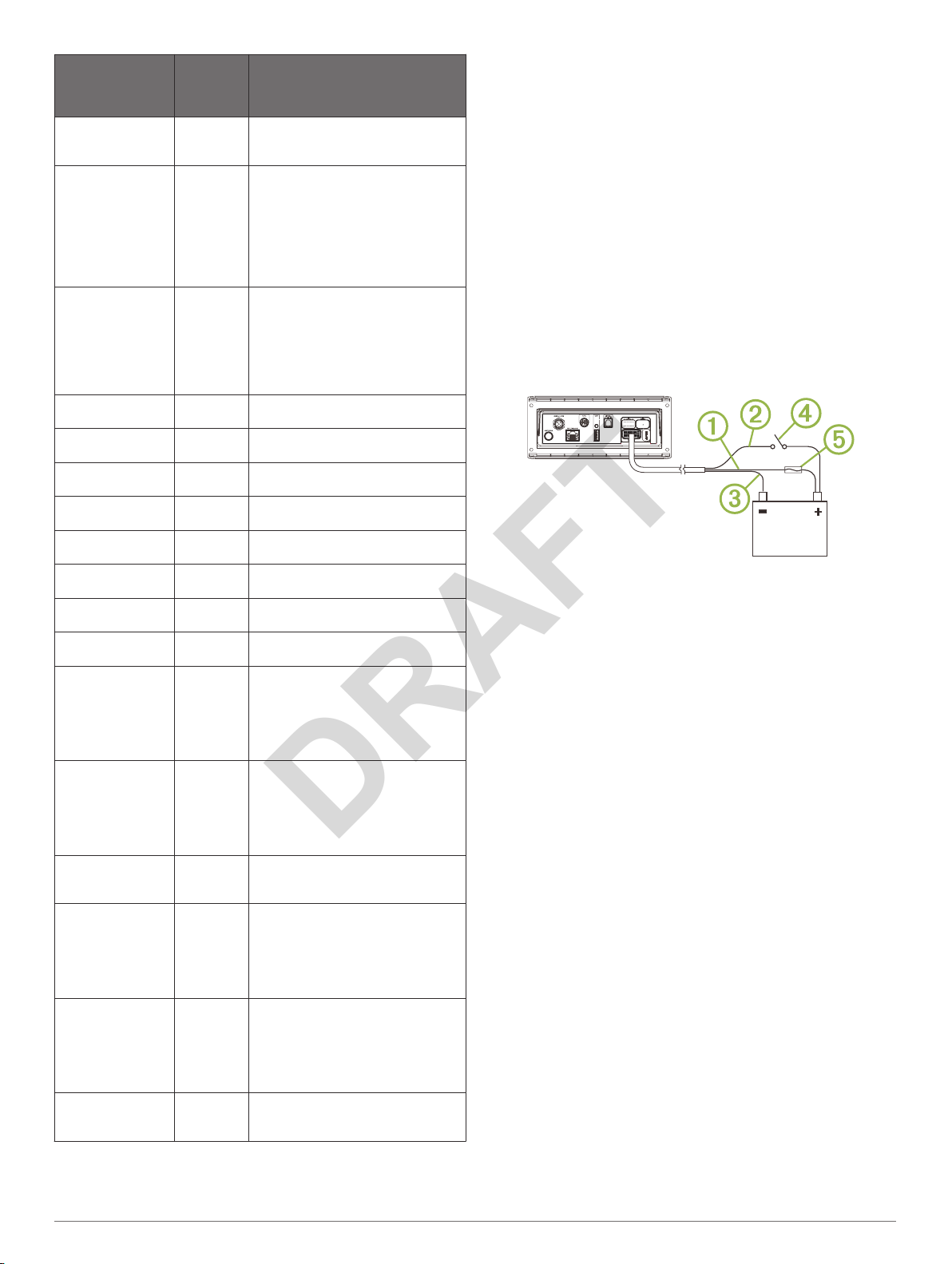
Route the yellow power À, red signal Á, and black ground
1
Â
wires to the battery, and route the wiring-harness plug to the
stereo.
Do not connect the wiring harness to the stereo until all of the
bare wire connections have been made.
Connect the black wire to the negative (-) battery terminal.
2
Complete an action:
3
• If you are routing the red wire through the ignition or
another manual switch Ã, connect the red signal wire to
the ignition or switch, install a 15 A fuse Ä on the yellow
wire as close to the battery as possible, and connect the
yellow wire to the positive (+) battery terminal.
• If you are not routing the red wire through the ignition or
switch, connect the red wire to the yellow wire, install a
15 A fuse as close to the battery as possible, and connect
both wires to the positive (+) battery terminal.
Speaker Zones
You can group speakers in one area into speaker zones. This
enables you to control the audio level of the zones individually.
For example, you could make the audio quieter in the cabin and
louder on deck.
Up to two pairs of speakers can be connected per channel of
each zone, in parallel. A zone can support no more than four
speakers using the on-board amplifier.
Zones 1 and 2 are powered by the on-board amplifier. To use
the RCA line outputs and the RCA subwoofer outputs for zones
1 and 2, you must connect external amplifiers.
Zones 3 and 4 are available as line-level outputs only. To use
the RCA line outputs and the RCA subwoofer outputs for zones
3 and 4, you must connect external amplifiers.
You can set the balance, volume limit, tone, subwoofer level,
subwoofer frequency, and name for each zone.
Connecting to Power
When connecting the stereo to power, you must connect both
power wires. You should connect the yellow power wire directly
Apollo RA770 Installation Instructions 3
Page 4
Single-Zone System Wiring Example
DRAFT
NMEA 2000 System Wiring Diagram
À
Á
Speakers
Water-tight connection
Extended System Wiring
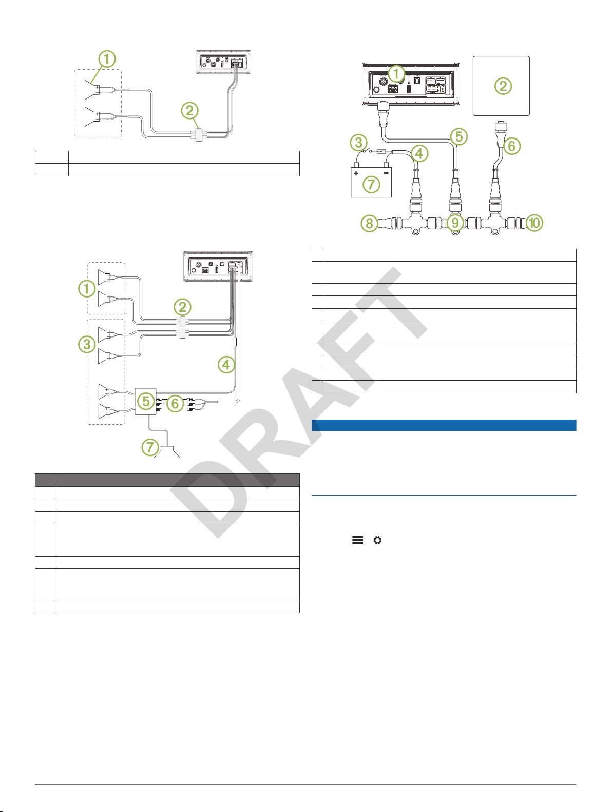
This diagram illustrates a system installation with an external
amplifier and subwoofer connected to zone 2 on the stereo. You
can connect an amplifier and subwoofer to any or all of the four
zones on the stereo.
Item Description
Zone 1 speakers
À
Water-tight connection
Á
Zone 2 speakers
Â
Amplifier-on signal wire
Ã
You must connect this wire to each amplifier connected to a zone
line out.
Powered amplifier connected to the zone 2 line out
Ä
Zone 2 line out and subwoofer out
Å
Each subwoofer cable provides a single mono output to a
powered subwoofer or subwoofer amplifier.
Subwoofer
Æ
Stereo
À
Supported chartplotter MFD or compatible FUSION
Á
remote control
In-line switch
Â
NMEA 2000 power cable
Ã
NMEA 2000 drop cable from the stereo, up to 6 m (20 ft.)
Ä
NMEA 2000 drop cable from the chartplotter MFD or compatible
Å
FUSION
9 to 16 Vdc power supply
Æ
NMEA 2000 terminator or backbone cable
Ç
NMEA 2000 T-connector
È
NMEA 2000 terminator or backbone cable
É
Configuring an Optional Wired Remote
The stereo is configured by default to work with a NMEA 2000
network, and the
when an optional remote is connected directly to the stereo.
Enabling this option when the stereo is connected to a NMEA
2000 network may damage other devices on the NMEA 2000
network.
If you connect an optional wired NRX remote directly to the
stereo, and not through a NMEA 2000
configuration is needed.
Select > >
1
Select an option:
2
• If you connected both your stereo and your optional wired
• If you connected the optional wired remote directly to the
NMEA 2000 remote control
NOTICE
NRX POWER option should be enabled only
network , additional
NMEA
.
remote to a NMEA 2000 network, make sure the NRX
POWER
remote to receive power from the NMEA 2000 network.
stereo through the NMEA 2000
POWER option. This enables the stereo to supply power
to the optional remote.
option is not selected. This enables the optional
connector, select the NRX
NMEA 2000
FUSION PartyBus Networking
The FUSION PartyBus networking feature allows you to connect
multiple compatible stereos and zone stereos together on a
network, using a combination of wired or wireless connections.
A FUSION PartyBus device connected to the network can
stream sources from and control media playback on another
FUSION PartyBus device connected to the network.
You can connect up to eight FUSION PartyBus devices on a
network.
4 Apollo RA770
Installation Instructions
Page 5
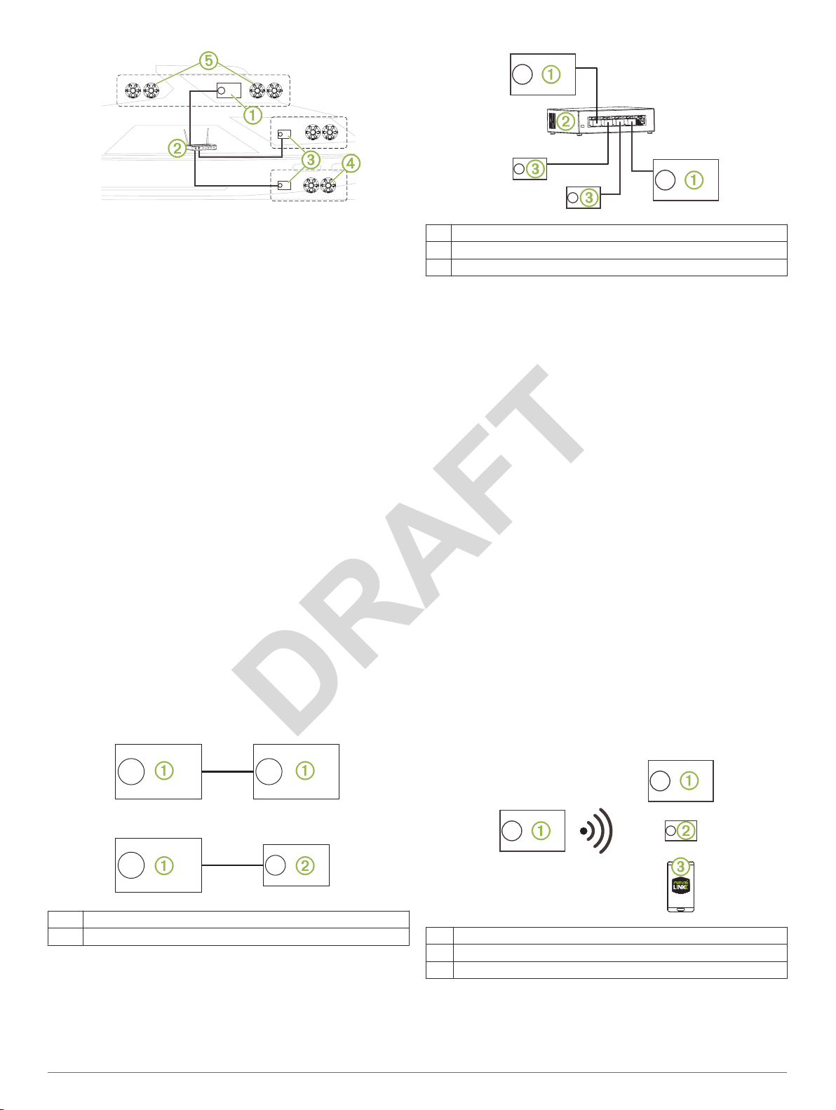
In the image above, a Apollo
DRAFT
wireless router Á and to two
You can connect a FUSION PartyBus zone stereo to a single
speaker zone Ã. You can connect a FUSION PartyBus stereo to
multiple speaker zones Ä to cover a larger area.
FUSION PartyBus devices connected to the network can stream
media from and control media playback on other devices on the
network, but cannot control the volume of other devices on the
network. You can adjust the volume of speakers or speaker
zones connected to the stereo only.
RA770 stereo À connects to a
Apollo SRX400 zone stereos Â.
Wired Networking Considerations
When you are planning your network installation, observe the
following considerations for all wired connections.
• Wired connections are more reliable than wireless
connections. When planning your network, you should use
network cables to connect FUSION PartyBus devices to the
network when possible.
• You must connect devices using standard Cat5e or Cat6
network cables with RJ45 connectors.
• You can use one network cable to directly connect two
compatible devices.
• You may need to use wired network switches and wired or
wireless network routers when you connect more than two
compatible stereos to a network.
• If you install a router on the network, it should be configured
to be the DHCP server by default. See your router
instructions for more information.
• If you do not install a router on the network, you must
configure one FUSION PartyBus device to be the DHCP
server.
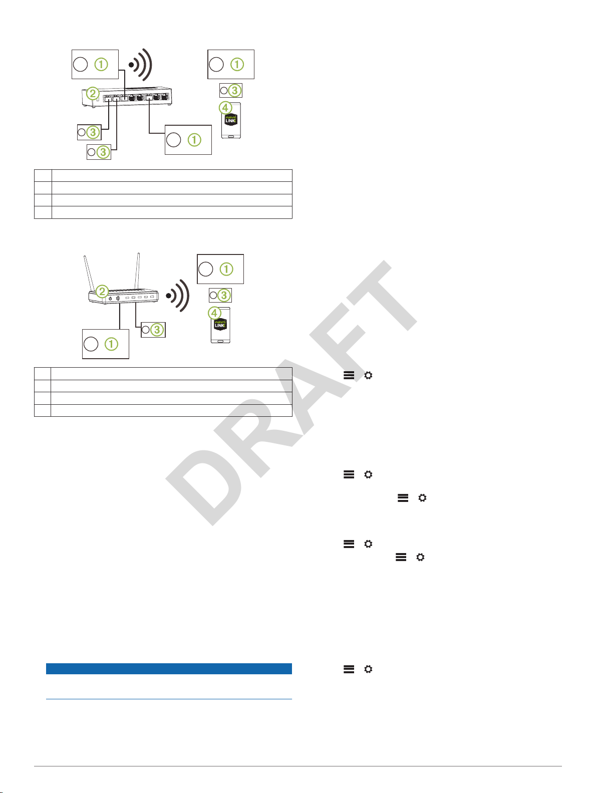
Wired Network Example for Direct Connections
You must configure one FUSION PartyBus device as a DCHP
server when connecting two devices together directly.
FUSION PartyBus stereo
À
Wired network switch or wired network router
Á
FUSION PartyBus zone stereo
Â
Wireless Networking Considerations
When you are planning your network, observe the following
considerations for all wireless connections.
• Wired connections are more reliable than wireless
connections. You should plan your network to use network
cables, but if it is not possible, FUSION PartyBus devices are
Wi‑Fi® compatible. You can connect them to wireless routers
or access points.
• You can configure a FUSION PartyBus device as a wireless
access point, so you can connect devices within wireless
range.
• If you install a wireless router on the network, it should be
configured to be the DHCP server by default. See your
wireless router instructions for more information.
• If you do not install a router or wireless router on the network,
you must configure one FUSION PartyBus device to be the
DHCP server.
• You can configure any FUSION PartyBus device on the wired
network to be a wireless access point, even if you install a
wireless router or additional wireless access points on the
network. This would be useful to allow access to devices in
range of the stereo but not in range of the other wireless
access points.
• If you connect a FUSION PartyBus device to the network
wirelessly, you cannot connect any additional wired FUSION
PartyBus devices to that device.
• You can connect a smartphone to the wireless network to
control any stereo on the network using the FUSION-Link
app.
Wireless Access Point Example
™
FUSION PartyBus stereo
À
FUSION PartyBus zone stereo
Á
Wired Network Example with a Switch or Router
You must use wired network switches, a wired network router, or
both to connect more than two FUSION PartyBus devices.
Apollo RA770 Installation Instructions 5
FUSION PartyBus stereo
À
FUSION PartyBus zone stereo
Á
Smartphone using the FUSION-Link
Â
app
Page 6
Wireless Network Example with a Wired Switch or Router
DRAFT
FUSION PartyBus stereo
À
Wired network switch or wired network router
Á
FUSION PartyBus zone stereo
Â
Smartphone using the FUSION-Link
Ã
Wireless Network Example with a Wireless Router or Access Point
FUSION PartyBus stereo
À
Wireless network router or wireless access point
Á
FUSION PartyBus zone stereo
Â
Smartphone using the FUSION-Link app
Ã
app.
Constructing a Network
You should have a basic understanding of networking when
building a network for FUSION PartyBus devices.
These instructions guide you through the basics of building and
configuring a network, and should apply to most situations. If
you need to perform advanced networking tasks, such as
assigning static IP addresses to devices on the network or
configuring advanced settings on a connected router, you may
need to consult a networking professional.
Determine the installation location of the FUSION PartyBus
1
devices you want to connect to the network.
NOTE:
connections. When planning your network, you should run
network cables instead of using wireless connections when
possible.
Determine the installation location of any needed network
2
routers or switches.
Route Cat5e or Cat6 network cable to the installation
3
locations of the stereos, switches, and router.
Connect the network cables to the stereos, switches, and
4
router.
Do not completely install the stereos yet. You should test the
network before you install the stereos.
Turn on all devices connected to the network, including
5
wireless devices.
Select an option:
6
• If you are not using a network router (wired or wireless),
Wired connections are more reliable than wireless
NOTICE
configure one FUSION PartyBus device to be the DHCP
server (Setting the FUSION PartyBus Device as the
DHCP Server
their default configuration (automatic IP).
• If you are using a network router (wired or wireless),
consult the documentation provided with your router to
configure the router as the DHCP server, if necessary. All
stereos should use their default configuration (automatic
IP).
Configure a stereo as a wireless access point, if necessary
7
(Setting the FUSION PartyBus Device as a Wireless Access
Point
, page 6).
Configure a FUSION PartyBus stereo or zone stereo to
8
connect to a wireless access point or router, if necessary
(Connecting the FUSION PartyBus Device to a Wireless
Access Point, page 6)
Test the network by viewing the list of FUSION PartyBus
9
devices from each device on the network and select an
option:
• If any FUSION PartyBus devices are not available to the
network, troubleshoot the network (Network
Troubleshooting, page 7)
• If all FUSION PartyBus devices are available to the
network, complete the installation for each stereo, if
necessary.
, page 6). All other stereos should use
.
.
Network Configuration
Setting the FUSION PartyBus Device as the DHCP Server
If you connected two FUSION PartyBus devices together
directly, or connected more than two together using a network
switch and did not install a router, you must configure only one
FUSION PartyBus stereo to be the DHCP server.
Select > >
SERVER > ENABLED > APPLY
Setting the FUSION PartyBus Device as a Wireless Access Point
Before you can connect additional FUSION PartyBus devices or
smartphones to a FUSION PartyBus device wirelessly, you must
configure at least one device as a wireless access point. This is
not necessary if you installed a wireless router or other wireless
access point on the network.
Select > >
1
To view and change the SSID, password, and other access
2
point settings select > >
WIFI ACCESS POINT SETTINGS
Connecting the FUSION PartyBus Device to a Wireless Access Point
Select > >
1
If necessary, select > > NETWORK > ADVANCED >
2
WIFI CLIENT SETTINGS.
The stereo scans for available wireless networks.
Select an available wireless network.
3
Enter the network password, if necessary.
4
Select APPLY
5
Resetting Network Settings
You can reset all network settings for this stereo to the factory
default values.
Select > >
Advanced Network Configuration
You can perform advanced networking tasks on a FUSION
PartyBus device, such as defining DHCP ranges and setting
static IP addresses. See the owner's manual for more
information.
NETWORK > ADVANCED > DHCP
NETWORK > WIFI ACCESS POINT
NETWORK > WIFI CLIENT
to connect to the wireless network.
NETWORK > RESET > YES
.
NETWORK > ADVANCED >
.
.
.
6 Apollo RA770
Installation Instructions
Page 7
Network Troubleshooting
DRAFT
If you cannot see or connect to FUSION PartyBus devices on
the network, check the following:
• Verify that only one device, either a stereo or a router, is
configured as a DCHP server.
• Verify that all FUSION PartyBus devices, network switches,
routers, and wireless access points are connected to the
network and turned on.
• Verify that wireless FUSION PartyBus devices are connected
to a wireless router or wireless access point on the network.
• If you have made configuration changes that might be
causing networking issues, reset all network settings to
factory defaults.
Stereo Information
Specifications
General
Weight 750 g (26.5 oz.)
Water resistance IEC 60529 IPX7 (front), IEC 60529
Operating temperature range From 0 to 50°C (from 32 to 122°F)
Storage temperature range From -20 to 70°C (from -4 to 158°F)
Input voltage From 10.8 to 16 Vdc
Current (max.) 15 A
Current (muted) Less than 900 mA
Current (off, standby mode
enabled)
Current (off, standby mode
disabled)
Fuse 15 A mini blade-type
NMEA 2000 LEN 1 (50 mA)
Bluetooth® wireless range Up to 10 m (30 ft.)
ANT® wireless range Up to 3 m (10 ft.)
Wireless frequencies/protocols Wi‑Fi
Compass-safe distance
IPX2 (rear)
120 mA
30 mA
2.4 GHz @ +15 dBm nominal
Bluetooth 2.4 GHz @ +10 dBm
nominal
ANT
2.4 GHz @ +4 dBm nominal
15 cm (5.9 in.)
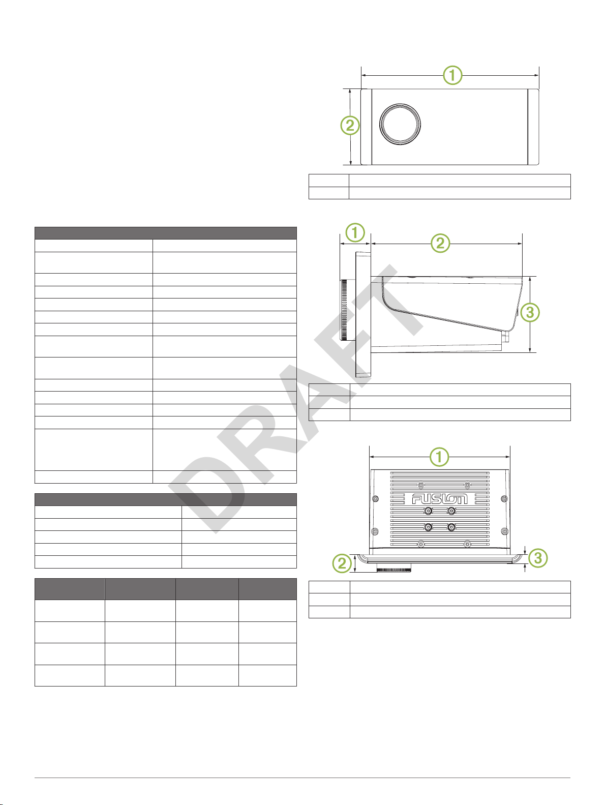
Stereo Dimension Drawings
Front Dimensions
À
Á
Side Dimensions
À
Á
Â
Top Dimensions
192 mm (7.56 in.)
82 mm (3.23 in.)
20.4 mm (0.8 in.)
99 mm (3.9 in.)
50 mm (1.97 in.)
On-board, Class D Amplifier
Output music power per channel 70 W max. x 4 at 2 ohms
Total output music power 280 W max.
Output power per channel 35 W RMS x 4 at 2 ohms
Line output level (max.) 6 V (peak to peak)
Aux input level (typical) 1 V RMS
Tuner Europe and
FM radio
frequency range
FM frequency
step
AM radio
frequency range
AM frequency
step
Australasia
87.5 to 108 MHz 87.5 to
50 kHz 200 kHz 50 kHz
522 to 1620 kHz 530 to
9 kHz 10 kHz 9 kHz
USA Japan
107.9 MHz
1710 kHz
76 to 95 MHz
522 to
1620 kHz
À
Á
Â
Registering Your Apollo
Help us better support you by completing our online registration
today.
• Go to www.fusionentertainment.com.
• Keep the original sales receipt, or a photocopy, in a safe
place.
164 mm (6.5 in.)
20.4 mm (0.8 in.)
10 mm (0.39 in.)
RA770
Software Updates
For best results, you should update the software in all FUSION
devices at the time of installation to ensure compatibility.
You can update the software using the FUSION-Link remote
control app on your compatible Apple or Android™ device, or
using a USB flash drive.
Apollo RA770 Installation Instructions 7
Page 8

To download the app and update the device software, go to the
DRAFT
Apple App StoreSM or the
updates and instructions on updating the device using the USB
flash drive, go to the device product page at
www.fusionentertainment.com/marine.
© 2018 Garmin Ltd. or its subsidiaries
Garmin®, ANT®, FUSION®, and the Fusion logo are trademarks of Garmin Ltd. or its
subsidiaries, registered in the USA and other countries. Apollo™, FUSION-Link™, and
FUSION PartyBus™ are trademarks of Garmin Ltd. or its subsidiaries. These trademarks
may not be used without the express permission of Garmin.
Apple® and App StoreSM are trademarks of Apple Inc. Android™ and Google Play™ are a
trademarks of Google Inc. Bluetooth® word mark and logos are owned by the Bluetooth
SIG, Inc. and any use of such marks by Garmin is under license. NMEA 2000®, and the
NMEA 2000 logo are registered trademarks of the National Marine Electronics
Association. SiriusXM® is a registered trademark of SiriusXM Radio Inc. Wi‑Fi® is a
registered mark of Wi-Fi Alliance Corporation. Other trademarks and trade names are
those of their respective owners.
Google Play
™
store. For software
www.fusionentertainment.com
 Loading...