

Page 1

Garmin Device
Installation Manual
DRAFT
190-00303-91 December, 2013 Revision 1
Page 2
© Copyright 2013
DRAFT
Garmin Ltd. or its subsidiaries
All Rights Reserved
Except as expressly provided herein, no part of this manual may be reproduced, copied,
transmitted, disseminated, downloaded or stored in any storage medium, for any purpose without
the express prior written consent of Garmin. Garmin hereby grants permission to download a
single copy of this manual and of any revision to this manual onto a hard drive or other electronic
storage medium to be viewed and to print one copy of this manual or of any revision hereto,
provided that such electronic or printed copy of this manual or revision must contain the complete
text of this copyright notice and provided further that any unauthorized commercial distribution of
this manual or any revision hereto is strictly prohibited.
Garmin International, Inc.
1200 E. 151st Street
Olathe, KS 66062 USA
Telephone: 913.397.8200
Aviation Panel-Mount Technical Support Line (Toll Free) 1.888.606.5482
www.garmin.com
Garmin (Europe) Ltd.
Liberty House, Bulls Copse Road
Hounsdown Business Park
Southampton, SO40 9RB U.K.
+44/ (0) 870.8501241
Garmin AT, Inc.
2345 Turner Rd., SE
Salem, OR 97302 USA
Telephone: 503.581.8101
RECORD OF REVISIONS
Revision Revision Date Description
A 12/17/13 Initial Release
Garmin Device Installation Manual 190-00303-91
Page A Rev. 1
Page 3
CURRENT REVISION DESCRIPTION
DRAFT
Revision
A
Page
Number(s)
All All Initial Release
Section
Number
DOCUMENT PAGINATION
Section Page Range
Table of Contents i – x
Section 1 1-1 – 1-6
Section 2 2-1 – 2-4
Section 3 3-1 – 3-22
Section 4 4-1 – 4-6
Appendix A A-1 – A-12
Appendix B B-1 – B-4
Appendix C C-1 – C-4
Appendix D D-1 – D-5
Description of Change
190-00303-91 Garmin Device Installation Manual
Rev. 1 Page i
Page 4
INFORMATION SUBJECT TO EXPORT CONTROL LAWS
WARNING
CAUTION
WARNING
Warnings are used to bring to the installer’s immediate attention that not only
damage to the equipment but personal injury may occur if the instruction is
disregarded.
CAUTION
Cautions are used to alert the individual that damage to equipment may
result if the procedural step is not followed to the letter.
NOTE
Notes are used to expand and explain the preceding step and provide further
understanding of the reason for the particular operation.
DRAFT
This document may contain information which is subject to the Export Administration Regulations
("EAR") issued by the United States Department of Commerce (15 CFR, Chapter VII, Subchapter C) and
which may not be exported, released, or disclosed to foreign nationals inside or outside of the United States
without first obtaining an export license. The preceding statement is required to be included on any and all
reproductions in whole or in part of this manual.
DEFINITIONS OF WARNINGS, CAUTIONS, AND NOTES
This product, its packaging, and its components contain chemicals known to the State of
California to cause cancer, birth defects, or reproductive harm. This Notice is being
provided in accordance with California's Proposition 65. If you have any questions or
would like additional information, please refer to our web site at www.garmin.com/prop65
Garmin Device Installation Manual 190-00303-91
Page ii Rev. 1
The front bezel, keypad, and display can be cleaned with a microfiber cloth or with
a soft cotton cloth dampened with clean water. DO NOT use any chemical
cleaning agents. Care should be taken to avoid scratching the surface of the
display.
.
Page 5

Aviation Limited Warranty
DRAFT
All Garmin avionics products are warranted to be free from defects in materials or workmanship for: two
years from the date of purchase for new Remote-Mount and Panel-Mount products; one year from the date
of purchase for new portable products and any purchased newly-overhauled products; six months for
newly-overhauled products exchanged through a Garmin Authorized Service Center; and 90 days for
factory repaired or newly-overhauled products exchanged at Garmin in lieu of repair. Within the
applicable period, Garmin will, at its sole option, repair or replace any components that fail in normal use.
Such repairs or replacement will be made at no charge to the customer for parts or labor, provided that the
customer shall be responsible for any transportation cost. This warranty does not apply to: (i) cosmetic
damage, such as scratches, nicks and dents; (ii) consumable parts, such as batteries, unless product damage
has occurred due to a defect in materials or workmanship; (iii) damage caused by accident, abuse, misuse,
water, flood, fire, or other acts of nature or external causes; (iv) damage caused by service performed by
anyone who is not an authorized service provider of Garmin; or (v) damage to a product that has been
modified or altered without the written permission of Garmin. In addition, Garmin reserves the right to
refuse warranty claims against products or services that are obtained and/or used in contravention of the
laws of any country.
THE WARRANTIES AND REMEDIES CONTAINED HEREIN ARE EXCLUSIVE AND IN LIEU OF
ALL OTHER WARRANTIES, WHETHER EXPRESS, IMPLIED OR STATUTORY, INCLUDING ANY
LIABILITY ARISING UNDER ANY WARRANTY OF MERCHANTABILITY OR FITNESS FOR A
PARTICULAR PURPOSE, STATUTORY OR OTHERWISE. THIS WARRANTY GIVES YOU
SPECIFIC LEGAL RIGHTS, WHICH MAY VARY FROM STATE TO STATE.
IN NO EVENT SHALL GARMIN BE LIABLE FOR ANY INCIDENTAL, SPECIAL, INDIRECT OR
CONSEQUENTIAL DAMAGES, WHETHER RESULTING FROM THE USE, MISUSE OR
INABILITY TO USE THE PRODUCT OR FROM DEFECTS IN THE PRODUCT. SOME STATES DO
NOT ALLOW THE EXCLUSION OF INCIDENTAL OR CONSEQUENTIAL DAMAGES, SO THE
ABOVE LIMITATIONS MAY NOT APPLY TO YOU.
Garmin retains the exclusive right to repair or replace (with a new or newly-overhauled replacement
product) the product or software or offer a full refund of the purchase price at its sole discretion. SUCH
REMEDY SHALL BE YOUR SOLE AND EXCLUSIVE REMEDY FOR ANY BREACH OF
WARRANTY.
Online Auction Purchases: Products purchased through online auctions are not eligible for warranty
coverage. Online auction confirmations are not accepted for warranty verification. To obtain warranty
service, an original or copy of the sales receipt from the original retailer is required. Garmin will not
replace missing components from any package purchased through an online auction.
International Purchases: A separate warranty may be provided by international distributors for devices
purchased outside the United States depending on the country. If applicable, this warranty is provided by
the local in-country distributor and this distributor provides local service for your device. Distributor
warranties are only valid in the area of intended distribution. Devices purchased in the United States or
Canada must be returned to the Garmin service center in the United Kingdom, the United States, Canada,
or Taiwan for service.
Garmin International, Inc. Garmin (Europe) Ltd.
1200 East 151st Street Liberty House, Bulls Copse Road
Olathe, Kansas 66062, U.S.A. Hounsdown Business Park
Phone:913/397.8200 Romsey, SO40 9RB, U.K.
FAX:913/397.0836 Phone:44/ (0) 870.8501241
FAX:44/ (0) 870.850125
190-00303-91 Garmin Device Installation Manual
Rev. 1 Page iii
Page 6

This page intentionally left blank
DRAFT
Garmin Device Installation Manual 190-00303-91
Page iv Rev. 1
Page 7

TABLE OF CONTENTS
DRAFT
PARAGRAPH PAGE
Section 1 Garmin Device Installation Overview ..............................................1-1
1.1 Unpacking Unit................................................................................................................ 1-1
1.2 Introduction...................................................................................................................... 1-1
1.3 System Overview.............................................................................................................1-2
1.4 General Garmin Device LRU Specifications................................................................... 1-2
1.5 Mounting.......................................................................................................................... 1-3
1.6 Wiring/Cabling Considerations ....................................................................................... 1-3
1.7 Wiring Harness Installation ............................................................................................. 1-4
Section 2 Garmin Device ....................................................................................2-1
2.1 Equipment Description .................................................................................................... 2-1
2.2 Electrical Specifications .................................................................................................. 2-2
2.3 Environmental Specifications .......................................................................................... 2-3
2.4 Installation Requirements ............................................................................................... 2-4
2.5 Installation Considerations .............................................................................................. 2-5
2.6 Mounting Requirements .................................................................................................. 2-5
2.7 Unit Installation ............................................................................................................... 2-5
2.8 Continued Airworthiness ................................................................................................. 2-5
2.9 Panel Cutout Template..................................................................................................... 2-5
Section 3 GPS/SiriusXM® Antenna Installation .............................................3-1
3.1 Garmin Antennas .............................................................................................................3-2
3.2 Antenna Mounting Considerations .................................................................................. 3-3
3.3 Teardrop Footprint Antenna Installation (GA 55 and GA 56) ........................................ 3-8
3.4 ARINC 743 Footprint Antenna Installation (GA 55A, GA 57X).................................. 3-15
3.5 Non-Structural Mount Installation................................................................................. 3-24
Section 4 Software, Configuration, Databases, and SiriusXM® Activation .4-1
4.1 Configuration Mode......................................................................................................... 4-1
4.3 Software Loading Procedure ........................................................................................... 4-2
4.4 Configuration Pages.........................................................................................................4-3
4.5 Garmin Database Updates ............................................................................................. 4-11
4.6 Sirius XM® Activation Instructions (Garmin Device only).......................................... 4-14
Appendix A Garmin Device Pinouts ................................................................A-1
A.1 Garmin Device ...............................................................................................................A-1
Section B Connector Installation Instructions.................................................B-1
B.1 Jackscrew Backshell Installation Instructions.................................................................B-1
190-00303-91 Garmin Device Installation Manual
Rev. 1 Page v
Page 8

PARAGRAPH PAGE
DRAFT
Appendix C Outline and Installation Drawings .............................................C-1
Appendix D Interconnect Example..................................................................D-1
Garmin Device Installation Manual 190-00303-91
Page vi Rev. 1
Page 9

LIST OF FIGURES
DRAFT
FIGURE PAGE
Section 1 Garmin Device Installation Overview ..............................................1-1
Figure 1-1 Coax Cable Installation....................................................................................... 1-5
Section 2 Garmin Device ....................................................................................2-1
Figure 2-1 Garmin Device .................................................................................................... 2-1
Figure 2-2 Garmin Device Mounting Accessories ............................................................... 2-4
Section 3 GPS/SiriusXM® Antenna Installation .............................................3-1
Figure 3-1 Recommended Antenna Placement .................................................................... 3-5
Figure 3-2 Carbon/Glass Buried Antenna Area.................................................................... 3-6
Figure 3-3 Glare Shield Buried Antenna Area ..................................................................... 3-7
Figure 3-4 Doubler Design, Teardrop Footprint Antenna, Skin Thickness
0.032" to 0.049" .................................................................................................................. 3-10
Figure 3-5 Doubler Design, Teardrop Footprint Antenna, Skin Thickness
0.049" to 0.051" ................................................................................................................... 3-10
Figure 3-6 Doubler Design, Teardrop Footprint Antenna, Skin Thickness
0.051" to 0.063" ................................................................................................................... 3-11
Figure 3-7 Sample Doubler Location, Teardrop Footprint Antenna, Metal Skin Aircraft. 3-11
Figure 3-8 Skin Cutout Detail, Teardrop Footprint Antenna, Skin Thickness
0.032" to 0.049" ................................................................................................................... 3-12
Figure 3-9 Skin Cutout Detail, Teardrop Footprint Antenna, Skin Thickness
0.049" to 0.051" ................................................................................................................... 3-12
Figure 3-10 Skin Cutout Detail, Teardrop Footprint Antenna, Skin Thickness
0.051" to 0.063" ................................................................................................................... 3-13
Figure 3-11 Doubler Installation, Teardrop Footprint Antenna, Skin Thickness
0.032" to 0.049" ................................................................................................................... 3-13
Figure 3-12 Doubler Installation, Teardrop Footprint Antenna, Skin Thickness
0.049" to 0.051" ................................................................................................................... 3-14
Figure 3-13 Doubler Installation, Teardrop Footprint Antenna, Skin Thickness
0.051" to 0.063" ................................................................................................................... 3-14
Figure 3-14 Doubler Design, ARINC 743 Footprint Antenna, Skin Thickness
0.032" to 0.049" ................................................................................................................... 3-17
Figure 3-15 Doubler Design, ARINC 743 Footprint Antenna, Skin Thickness
0.049" to 0.051" ................................................................................................................... 3-18
Figure 3-16 Doubler Design, ARINC 743 Footprint Antenna, Skin Thickness
0.051" to 0.063" ................................................................................................................... 3-19
Figure 3-17 Sample Doubler Location, ARINC 743 Antenna, Metal Skin Aircraft .......... 3-20
Figure 3-18 Skin Cutout Detail, ARINC 743 Footprint Antenna, Skin Thickness
0.032" to 0.049" ................................................................................................................... 3-20
Figure 3-19 Skin Cutout Detail, ARINC 743 Footprint Antenna, Skin Thickness
0.049" to 0.051" ................................................................................................................... 3-21
190-00303-91 Garmin Device Installation Manual
Rev. 1 Page vii
Page 10

FIGURE PAGE
DRAFT
Figure 3-20 Skin Cutout Detail, ARINC 743 Footprint Antenna, Skin Thickness
0.051" to 0.063" ................................................................................................................... 3-21
Figure 3-21 Doubler Installation, ARINC 743 Footprint Antenna, Skin Thickness
0.032" to 0.049" ................................................................................................................... 3-22
Figure 3-22 Doubler Installation, ARINC 743 Footprint Antenna, Skin Thickness
0.049" to 0.051" ................................................................................................................... 3-22
Figure 3-23 Doubler Installation, ARINC 743 Footprint, Skin Thickness
0.051" to 0.063" ................................................................................................................... 3-23
Figure 3-24 Installation of ARINC 743 Footprint Antenna .............................................. 3-23
Figure 3-25 Generic Non-structural ARINC 743 Footprint Antenna Installation.............. 3-25
Figure 3-26 Example Bracket Antenna Mounting Under Glareshield ............................... 3-25
Figure 3-27 Example Non-structural Antenna Mounting Under Glareshield .................... 3-26
Figure 3-28 Example Teardrop Antenna Installation In Airframe Under Fabric Skin....... 3-27
Figure 3-29 Example ARINC 743 Footprint In Airframe Under Fabric Skin.................... 3-27
Figure 3-30 Example Non-structural Antenna Mounting On Airframe ............................. 3-28
Figure 3-31 Example Teardrop Footprint Antenna Mounting Under Fabric Skin ............. 3-29
Section 4 Software, Configuration, Databases, and SiriusXM® Activation .4-1
Appendix A Garmin Device Pinouts................................................................A-1
Figure A-1 View of J4601 Connector from Back of Unit .................................................. A-1
Figure A-2 View of J4602 Connector from Back of Unit .................................................. A-2
Figure A-3 View of J4603 Connector from Back of Unit .................................................. A-4
Section B Connector Installation Instructions.................................................B-1
Figure B-1 Shield Install onto a Jackscrew Backshell (78 pin example) .............................B-2
Figure B-2 Method A.1 for Shield Termination ..................................................................B-3
Figure B-3 Insulation/Contact Clearance .............................................................................B-5
Figure B-4 Method A.2 (Daisy Chain) for Shield Termination ...........................................B-7
Figure B-5 Method B.1 (Quick Term) for Shield Termination ...........................................B-9
Figure B-6 Method B.2 (Daisy Chain-Quick Term) for Shield Termination.....................B-10
Figure B-7 Daisy Chain between Methods A and B ..........................................................B-11
Figure B-8 D-Sub Spliced Signal Wire illustration ............................................................B-12
Appendix C Outline and Installation Drawings .............................................C-1
Figure C-1 Garmin Device Outline Drawing .......................................................................C-1
Figure C-2 Garmin Device Installation Drawing .................................................................C-2
Figure C-3 Garmin Device Nutplate Drawing (not to scale)................................................C-3
Figure C-4 Garmin Device Panel Cutout Drawing...............................................................C-4
Appendix D Interconnect Example..................................................................D-1
Figure D-1 Garmin Device Interconnect Example .............................................................. D-1
Garmin Device Installation Manual 190-00303-91
Page viii Rev. 1
Page 11

LIST OF TABLES
DRAFT
TABLE PAGE
Section 1 Garmin Device Installation Overview ..............................................1-1
Table 1-1 Garmin Device LRU Part Numbers ..................................................................... 1-2
Table 1-2 Contents of Garmin Device Assembly (010-01057-XX)..................................... 1-2
Table 1-3 Garmin Device LRU Power Requirements .......................................................... 1-2
Table 1-4 Garmin Device LRU Physical Specifications ...................................................... 1-3
Table 1-5 Pin Contact and Crimp Tools Part Numbers ........................................................ 1-4
Section 2 Garmin Device ....................................................................................2-1
Table 2-1 Garmin Device Supply Voltages.......................................................................... 2-2
Table 2-2 Garmin Device Power Requirements ................................................................... 2-2
Table 2-3 Garmin Device GPS Specifications ..................................................................... 2-2
Table 2-4 Garmin Device Supported Antennas.................................................................... 2-3
Table 2-5 Garmin Device Required Accessories.................................................................. 2-4
Table 2-6 Contents of Garmin Device Connector Kit (011-01921-00)................................ 2-4
Section 3 GPS/SiriusXM® Antenna Installation .............................................3-1
Table 3-1 Supported Garmin Antennas ................................................................................ 3-2
Table 3-2 GPS Antenna Minimum Requirements................................................................ 3-2
Table 3-3 SiriusXM® Satellite Radio Antenna Minimum Requirements........................... 3-3
Table 3-4 Teardrop Footprint Antenna Doubler Design and Installation............................. 3-8
Table 3-5 ARINC 743 Footprint Antenna Doubler Design and Installation...................... 3-15
Table 3-6 Minimum Distance Required Between Tube Structure and Antenna ................ 3-29
Section 4 Software, Configuration, Databases, and SiriusXM® Activation .4-1
Appendix A Garmin Device Pinouts ...............................................................A-1
Table A-1 J4602................................................................................................................... A-2
Table A-2 Aircraft Power .................................................................................................... A-4
Table A-3 Configuration Module ........................................................................................ A-5
Table A-4 CDU System ID Program Pins ........................................................................... A-5
Table A-5 Demo Mode ........................................................................................................ A-5
Table A-6 RS-232................................................................................................................ A-6
Table A-7 Lighting .............................................................................................................. A-6
Table A-8 Mono Audio........................................................................................................ A-6
Table A-9 Stereo Audio....................................................................................................... A-7
Section B Connector Installation Instructions.................................................B-1
Table B-1 Parts supplied for a Shield Block Installation (Figure B-1) ................................B-1
Table B-2 Parts not supplied for a Shield Block Installation (Figure B-1) ..........................B-1
Table B-3 Shielded Cable Preparations for Garmin Connectors..........................................B-3
Table B-4 Shielded Cable Preparations – (Quick Term)......................................................B-9
190-00303-91 Garmin Device Installation Manual
Rev. 1 Page ix
Page 12

This page intentionally left blank
DRAFT
Garmin Device Installation Manual 190-00303-91
Page x Rev. 1
Page 13

1 GARMIN DEVICE INSTALLATION OVERVIEW
NOTE
DRAFT
1.1 Unpacking Unit
Carefully unpack the equipment and make a visual inspection of the unit for evidence of damage incurred
during shipment. If the unit is damaged, notify the carrier and file a claim. To justify a claim, save the
original shipping container and all packing materials. Do not return the unit to Garmin until the carrier has
authorized the claim.
Retain the original shipping containers for storage. If the original containers are not available, a separate
cardboard container should be prepared that is large enough to accommodate sufficient packing material to
prevent movement.
1.2 Introduction
This manual provides an overview of the Garmin Device and its mechanical and electrical installation
aspects.
The Garmin Device is not a TSO-certified product and has received no FAA approval or
endorsement, and is therefore not suitable for installation in a type-certificated aircraft.
The following outline describes the organization of this manual:
Section 1 This section gives a basic overview of the Garmin Device system and interface.
This section contains generic information that pertains to all components of the
Garmin Device system, such as wiring and backshell considerations.
Section 2 This section describes the electrical and installation aspects of the Garmin Device.
Section 3 This section describes the electrical and installation aspects of the Garmin GPS
and SiriusXM® antennas.
Section 4 This section contains software, configuration, database, and SiriusXM® activation
information.
Section 5 This section contains post-installation checkout for the Garmin Device.
Appdx A
Appdx B This section contains outline and installation drawings for the Garmin Antennas
Appdx C
Appdx D
This section contains pinout information for all Garmin Device LRU’s.
and Garmin Device units.
This section connector installation instructions.
This section contains interconnect drawings for the Garmin Device.
190-00303-91 Garmin Device Installation Manual
Rev. 1 Page 1-1
Page 14

1.3 System Overview
DRAFT
TBD
1.4 General Garmin Device LRU Specifications
1.4.1 Garmin LRU Part Numbers
Table 1-1 Garmin Device LRU Part Numbers
LRU Unit Only Part Number Assembly Part Number
Garmin Device Americas DB 011-02920-00 010-01057-00
Garmin Device Atlantic DB 011-02920-00 010-01057-01
Garmin Device Pacific DB 011-02920-00 010-01057-02
Garmin Device Americas DB 011-02920-01 010-01057-10
Table 1-2 Contents of Garmin Device Assembly (010-01057-XX)
Item Garmin P/N Quantity
Garmin Device 011-01747-XX 1
Cleaning Cloth 013-00380-00 1
SD Card, Dummy 145-00561-00 1
Important Safety and Product Information 190-00720-52 1
Jeppesen Free Single Update 190-10003-03 1
1.4.2 Power Specifications
All LRUs are capable of operating at either 14 or 28 VDC. See Table 1-3 for current draw specifications.
Table 1-3 Garmin Device LRU Power Requirements
LRU Supply Voltage Approx. Current Draw
Garmin Device 10-32 Vdc
2.0 Amp @ 14Vdc
1.0 Amp @ 28Vdc
Garmin Device Installation Manual 190-00303-91
Page 1-2 Rev. 1
Page 15
1.4.3 Physical Specifications
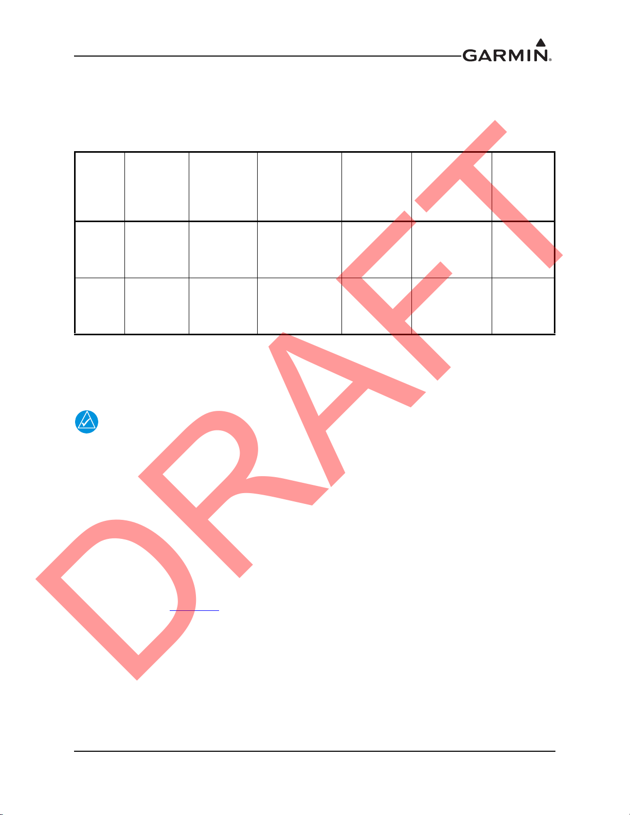
NOTE
DRAFT
Measurements do not account for space or weight of wiring, cables, etc.
Table 1-4 Garmin Device LRU Physical Specifications
Depth Behind
LRU
Garmin
Device
Garmin
Device
1.4.4 Cooling Requirements
While no forced cooling air is required for the Garmin Device, it is highly recommended that the air behind
the panel be kept moving (by ventilation or a fan).
Bezel
Width
10.85
inches
(275.5
mm)
10.85
inches
(275.5
mm)
Bezel
Height
7.82 inches
(198.6 mm)
7.82 inches
(198.6 mm)
Panel
(includes
recommended
backshell)
3.57 inches
(90.7 mm)
3.57 inches
(90.7 mm)
Unit Weight
(Unit Only)
4.55 lbs
(2.064 kg)
4.66 lbs
(2.112 kg)
Unit Weight
(w/connector)
TBD
TBD
Nutplate
Weight
0.045 lbs
(.0204 kg)
0.045 lbs
(.0204 kg)
Avoid installing the Garmin Device LRUs near heat sources. If this is not possible, ensure
that additional cooling is provided. Allow adequate space for installation of cables and
connectors. The installer will supply and fabricate all of the cables. All wiring should be
in accordance with FAA AC 43.13-1B and AC 43.13-2A.
1.5 Mounting
Refer to Sections 2 and 3 for specific mounting instructions for each component of the Garmin Device, and
to Appendix C for Outline & Installation Drawings.
1.6 Wiring/Cabling Considerations
Use MIL-W-22759/16 (or other approved wire) AWG #22 or larger wire for all connections unless
otherwise specified. The standard pin contacts supplied in the connector kit are compatible with up to
AWG #22 wire. See Figure D-1
than one LRU sharing a common circuit breaker, sizing and wire gauge is based on aircraft circuit breaker
layout, length of wiring, current draw on units, and internal unit protection characteristics. Do not attempt
to combine more than one unit on the same circuit breaker.
RG400 or RG142 coaxial cable with 50 Ω nominal impedance and meeting applicable aviation regulations
should be used for the installation.
for power/ground wire info. In cases where some installations have more
190-00303-91 Garmin Device Installation Manual
Rev. 1 Page 1-3
Page 16
1.7 Wiring Harness Installation
CAUTION
DRAFT
Allow adequate space for installation of cables and connectors. Ensure that routing of the wiring does not
come in contact with sources of heat, RF or EMI interference. Analog Input wires routed too close to
spark plugs, plug wires, or magnetos may result in erratic readings.
The installer shall supply and fabricate all of the cables. The connector is available in the Garmin Device
Connector Kit (011-01921-10). Electrical connections are made through a 50 pin D-subminiature
connector for the Garmin Device units. Appendix A defines the electrical characteristics of all input and
output signals. Required connectors and associated hardware are supplied with the connector kit.
Check wiring connections for errors before connecting any wiring harnesses.
Incorrect wiring could cause internal component damage.
Table 1-5 Pin Contact and Crimp Tools Part Numbers
LRU
Garmin
Device
Insertion/Extraction tools from ITT Cannon are all plastic; others are plastic with metal tip.
Non-Garmin part numbers shown are not maintained by Garmin and consequently are subject to
change without notice.
1.7.1 Cable Location Considerations
Use cable meeting the applicable aviation regulation for the interconnect wiring. Any cable meeting
specifications is acceptable for the installation. When routing cables, observe the following precautions:
• All cable routing should be kept as short and as direct as possible.
• Check that there is ample space for the cabling and mating connectors.
• Avoid sharp bends in cabling.
• Avoid routing near aircraft control cables.
• Avoid routing cables near power sources (e.g., 400 Hz generators, trim motors, etc.) or
near power for fluorescent lighting.
• Route the GPS antenna cable as far as possible away from all COM transceivers and
antenna cables.
Contact
Type
Socket,
MilCrimp,
Size 20
Garmin
Contact Part
Number
336-00022-02
Recommended
Positioner
M22520/2-08,
Daniels K13-1
Recommended
Insertion/
Extraction Tool
M81969/1-04 for
size 22D pins
and M81969/102 for size 20
pins
Recommended
Hand Crimping
Tool
M22520/2-01
Garmin Device Installation Manual 190-00303-91
Page 1-4 Rev. 1
Page 17
1.7.2 Cable Installation
DRAFT
1. Route the coaxial cable to the unit location. Secure the cable in accordance with good aviation
practices.
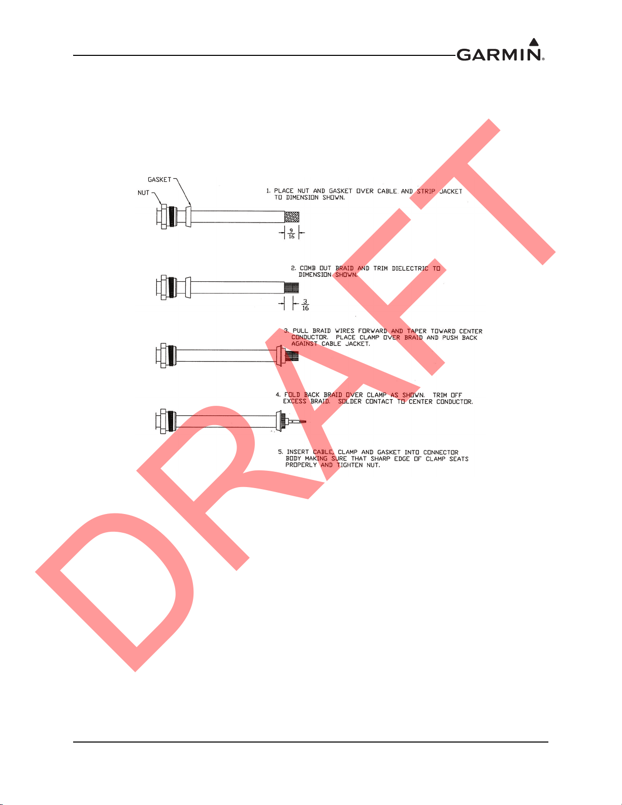
2. Trim the coaxial cable to the desired length and install the BNC connector (330-00087-00) per the
cabling instructions on Figure 1-1. If the connector is provided by the installer, follow the connector manufacturer’s instructions for cable preparation.
Figure 1-1 Coax Cable Installation
3. Contacts for the 50 pin connectors must be crimped onto the individual wires of the aircraft wiring
harness. Table 1-5 list contact part numbers (for reference) and recommended crimp tools.
1.7.3 Backshell Assemblies
Connector kits include backshell assemblies. Garmin’s backshell connectors give the installer the ability
to quickly and easily terminate shield grounds at the backshell housing. The instructions needed to
assemble the backshell connector w/Shield Block grounding system are located in Appendix B.
190-00303-91 Garmin Device Installation Manual
Rev. 1 Page 1-5
Page 18

This page intentionally left blank
DRAFT
Garmin Device Installation Manual 190-00303-91
Page 1-6 Rev. 1
Page 19

2 GARMIN DEVICE
Insert picture
DRAFT
Figure 2-1 Garmin Device
2.1 Equipment Description
The Garmin Device is not suitable for installation in a type-certificated aircraft.
The Garmin Device is mounted flush to the aircraft instrument panel using four #6 screws. The Garmin
Device is available in two models. The Garmin Device is a Garmin Display Unit with a GPS receiver. The
Garmin Device provides these same features plus an SiriusXM
2.1.1 Navigation Functions
• Display of position and ground speed
• Display of stored navigation and map databases
• Area navigation functions using the determined position/velocity and stored navigation data
• Advisory approach navigation functions and associated databases
® receiver.
190-00303-91 Garmin Device Installation Manual
Rev. 1 Page 2-1
Page 20
2.1.2 Interface Summary
DRAFT
The Garmin Device uses RS-232 communications interfaces. The Garmin Device communicates with the
following Garmin LRUs:
• GDL 39/GDL39R
• GNS 400/500 Series Units
•GTN 6XX/7XX
• GTX 327/330 Transponder
• SL30 Nav/Comm Transceiver
• SL40 Comm Transceiver
2.2 Electrical Specifications
2.2.1 Electrical Characteristics
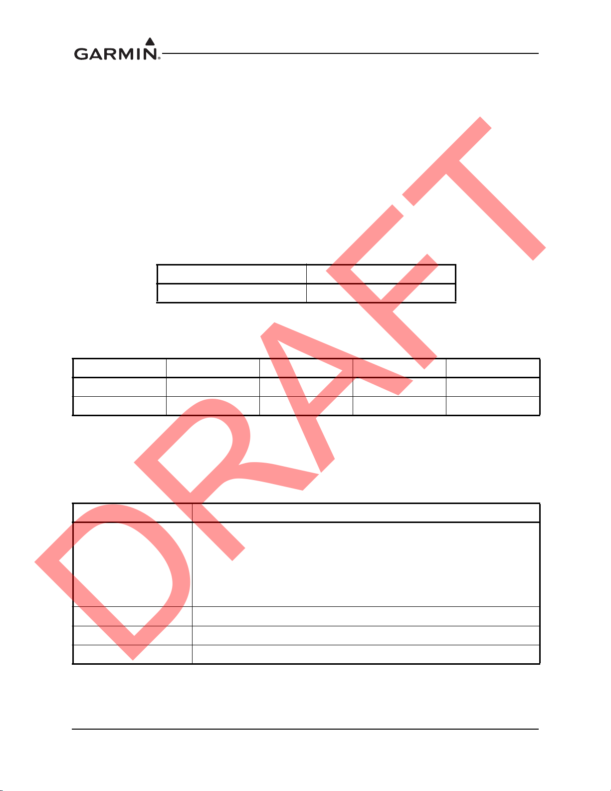
Table 2-1 Garmin Device Supply Voltages
Characteristics Specifications
Power Requirements 14/28 VDC
2.2.2 Power Consumption
Table 2-2 Garmin Device Power Requirements
LRU 14V (Maximum) 14V (Typical) 28V (Maximum) 28V (Typical)
Garmin Device 3.0 Amp 1.8 Amp 1.9 Amp 0.9 Amp
Garmin Device 3.5 Amp 2.0 Amp 2.0 Amp 1.0 Amp
2.2.3 GPS Specifications
The Garmin Device uses a high-sensitivity GPS receiver that continuously tracks and uses up to 12
satellites to compute and update its position.
Table 2-3 Garmin Device GPS Specifications
Characteristics Specifications
a) Warm Start (position known to 10 nm, time known to 10 minutes, with
valid almanac and ephemeris): Less than 5 seconds
Acquisition Time
Update Rate 5/second, continuous
Positional Accuracy <10 meters
Antenna Power Supply Voltage (4.5 to 5.0), current (50 mA max)
b) Cold Start (position known to 300 nm, time known to 10 minutes, with
valid almanac): Less than 45 seconds
c) AutoLocate™ (with almanac, without initial position or time): Less than 60
seconds
Garmin Device Installation Manual 190-00303-91
Page 2-2 Rev. 1
Page 21
2.2.4 Antennas
NOTE
DRAFT
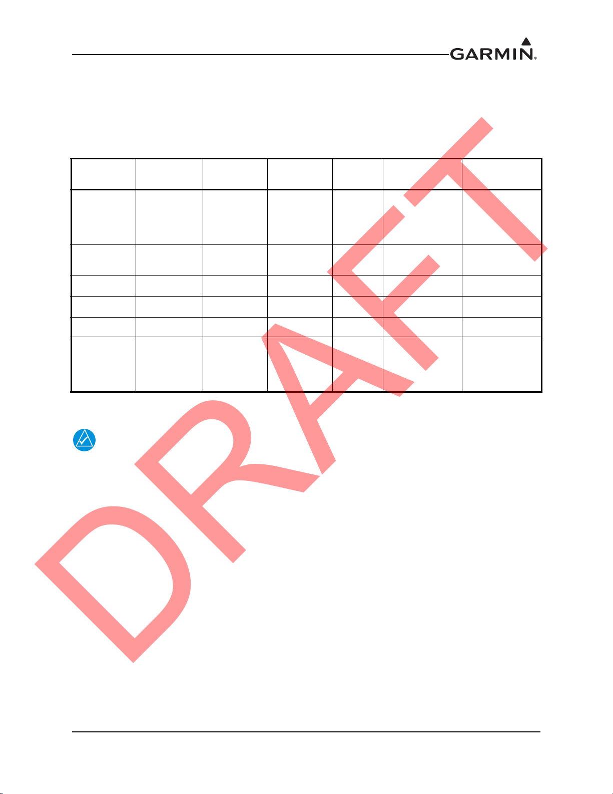
Table 2-4 lists Garmin and non-Garmin antennas currently supported by the Garmin Device. Refer to
Section 3 for Garmin antenna installation information. For non-Garmin antennas, follow the
manufacturer’s installation instructions.
Table 2-4 Garmin Device Supported Antennas
Model
GA 26C
GA 26XM
GA 55 Stud Mount TNC
GA 55A ARINC 743 TNC
GA 56 Stud Mount BNC GPS Garmin 011-00134-00 010-10040-01
GA 57X [1]
[1] The GPS antenna connector is BNC type. The SiriusXM® antenna connector is TNC type.
The GPS antenna should provide a gain of 16 to 25dB, and requires a 4.5V to 5V supply
voltage that can provide 50mA max.
Mount
Style
Suction
Cup,
Magnetic or
Flange Mt
Ground
Plane Mt
Screw
Mount,
ARINC 743
Footprint
Conn Type
BNC GPS Garmin 011-00149-04 010-10052-04
TNC
BNC
TNC
Antenna
Type
SiriusXM®
SiriusXM®
SiriusXM®
GPS
SiriusXM
®
Mfr
Garmin 013-00268-10 010-11373-00
Garmin 011-01033-00 010-10600-01
Garmin 011-01153-00 010-10598-00
Garmin 011-01032-10 010-11370-10
Antenna Part
Number
Garmin Order
Number
2.3 Environmental Specifications
The Garmin Device has an Operating Temperature Range of -20°C to +60°C.
190-00303-91 Garmin Device Installation Manual
Rev. 1 Page 2-3
Page 22
2.4 Installation Requirements
Insert picture
DRAFT
2.4.1 Required Accessories
Each of the following accessories is provided in the Installation Kit (010-12150-00), which is sold
separately. The connector kit is required to install the unit (Figure 2-2). The Garmin Device Nutplate is
available to reinforce the panel cutout in thin panel installations.
Table 2-5 Garmin Device Required Accessories
Item Garmin P/N Quantity
Garmin Device Connector Kit* 011-01921-10 1
Garmin Device Nutplate* 115-01725-01 1
*Included in Garmin Device Assembly (010-00667-XX) Table 1-1
Table 2-6 Contents of Garmin Device Connector Kit (011-01921-00)
Item Garmin P/N Quantity
Sub-Assy,bkshl w/Hdw,Jackscrew 011-01855-04 1
Conn, Rcpt,D-Sub, Crimp Socket, C 330-00625-50 1
Contact, Sckt, D-Sub, Crimp, Size 20 336-00022-02 30
2.4.2 Additional Equipment Required
A 3/32” hex drive tool is required to secure the Garmin Device to the panel as described in Section 2.7 Unit
Installation.
Figure 2-2 Garmin Device Mounting Accessories
Garmin Device Installation Manual 190-00303-91
Page 2-4 Rev. 1
Page 23

2.5 Installation Considerations
NOTE
DRAFT
Fabrication of a wiring harness is required. Sound mechanical and electrical methods and practices are
recommended for installation of the Garmin Device. Refer to Section 1.6 for wiring considerations,
Appendix A.1 for pinouts.
Connector kits include backshell assemblies. Garmin’s backshell connectors give the installer the ability
to quickly and easily terminate shield grounds at the backshell housing. The instructions needed to
assemble the backshell connector w/Shield Block grounding system are located in Appendix B.
The Garmin Device rear connector (J3701) is electrically isolated. For installations
using shielded cables, a ground pin must be tied to the connector shell.
2.6 Mounting Requirements
Refer to Appendix C for outline and installation drawings.
2.7 Unit Installation
The Garmin Device is installed by holding the unit flush with the instrument panel and fastening the four
3/32” hex socket head screws to the panel as shown in Figure C-1.1 and C-1.2.
2.8 Continued Airworthiness
Maintenance of the Garmin Device is “on condition” only. Periodic maintenance of the Garmin Device is
not required. Instructions for Continued Airworthiness (ICA) are not required for this product under 14
CFR Part 21 since the Garmin Device has received no FAA approval or endorsement.
2.9 Panel Cutout Template
A template that can be used for marking the panel for cutout is available from www.garmin.com. See
Figure C-1.3 for complete dimensions.
190-00303-91 Garmin Device Installation Manual
Rev. 1 Page 2-5
Page 24

This page intentionally left blank
DRAFT
Garmin Device Installation Manual 190-00303-91
Page 2-6 Rev. 1
Page 25

3 GPS/SIRIUSXM® ANTENNA INSTALLATION
NOTE
DRAFT
This section contains general information as well as installation information for GPS and SiriusXM
antennas. Use this section to mount the GPS/SiriusXM antenna(s).
In an installation with multiple Garmin Device units, each Garmin Device can be configured to use its own
internal GPS receiver, or to receive GPS data transmitted by another Garmin Device. A minimum of one
GPS antenna is required for installations using more than one Garmin Device unit, as the Garmin Device
will “share” the GPS information with all Garmin Device units. Additional GPS antennas may be used for
redundancy, but are not required.
Only a single GPS antenna is required for installations using more than one
Garmin Device unit, as the Garmin Device will “share” the GPS information with all
Garmin Device units.
190-00303-91 Garmin Device Installation Manual
Rev. 1 Page 3-1
Page 26
3.1 Garmin Antennas
DRAFT
If using a Garmin GA 26C or GA 26XM, refer to the accompanying installation instructions
(190-00082-00 or 190-00522-03). For GA 55/55A, or GA 56 or GA 57X antennas, refer to this section
and the outline and installation drawings beginning with Figure C-1
.
Garmin recommends the antennas shown in Table 3-1. However, any equivalent GPS or SiriusXM
antenna that meets the specifications listed in Table 3-2 and Table 3-3
Table 3-1 Supported Garmin Antennas
Model Part Number Description Weight Mounting Configuration
GA 26C 011-00149-04 GPS Antenna NA
GA 26XM 013-00268-10
GA 55 011-01033-00
GA 55A 011-01153-00
GA 56 011-00134-00 GPS Antenna
GA 57X 011-01032-10
SiriusXM®
Antenna
SiriusXM®
Antenna
SiriusXM®
Antenna
GPS/Siri-
usXM
®
Antenna
NA
0.25 lbs
(0.11 kg)
0.43 lbs
(0.20 kg)
0.24 lbs
(0.11 kg)
0.47 lbs
(0.21 kg)
should work with the system.
Flange, Magnetic, or Suction Cup
Mount (for in-cabin mounting)
Flange, Magnetic, or Suction Cup
Mount (for in-cabin mounting)
Stud mount (Tear-drop form factor)
Thru-mount (ARINC 743 style
mount)
Stud mount (Tear-drop form factor)
Thru-mount (ARINC 743 style
mount)
®
Table 3-2 GPS Antenna Minimum Requirements
Characteristics Specifications
Frequency Range 1565 to 1585 MHz
Gain 16 to 25 dB typical, 40 dB max.
Noise Figure <4.00 dB
Nominal Output Impedance 50 ohms
Supply Voltage 4.5 to 5.5 VDC
Supply Current up to 50 mA
Output Connector BNC
Garmin Device Installation Manual 190-00303-91
Page 3-2 Rev. 1
Page 27
Table 3-3 SiriusXM
DRAFT
Characteristics Specifications
Frequency Range 2332.5 to 2345 MHz
Gain (Typical) 24 dB*
Noise Figure <1.2 dB
Nominal Output Impedance 50 ohms
Supply Voltage 3.6 to 5.5 VDC
Supply Current (maximum) 55 mA
Operating Temperature Gain -50 to +85° C
*For each 1 dB gain over 24 dB, add 1 dB of attenuation into the antenna cable path between the
antenna and the Garmin Device.
It is the installer’s responsibility to ensure that their choice of antenna meets FAA standards according to
the specific installation. This installation manual discusses only the antennas listed in Table 3-1
antennas may be acceptable but their installation is not covered by this manual.
There are several critical factors to take into consideration before installing an antenna for a satellite
communications system. These factors are addressed in the following sections.
3.2 Antenna Mounting Considerations
® Satellite Radio Antenna Minimum Requirements
. Other
The information in this section does not pertain to in-cabin (internal) mounted antennas such as the
GA 26C, refer to the accompanying installation instructions (190-00082-00).
No special precautions need be taken to provide an electrical bonding path between the GPS Antenna and
the aircraft structure.
3.2.1 VHF COM/GPS Interference
On some installation VHF COM transceivers, Emergency Locator Transmitter (ELT) antennas, and
Direction Finder (DF) receiver antennas can re-radiate through the GPS antenna. The Garmin Device does
not interfere with its own GPS receiver. However, placement of the GPS antenna relative to a COM
transceiver and COM antenna, ELT antenna, and DF receiver antenna is critical.
Use the following guidelines, in addition to others in this document, when locating the Garmin Device and
its antennas.
• GPS Antenna—Locate as far as possible from all COM antennas and all COM
transceivers, ELT antennas, and DF antennas. The GPS antenna is less susceptible to
harmonic interference if a 1.57542 GHz notch filter is installed on the COM transceiver
antenna output.
• Locate the Garmin Device as far as possible from all COM antennas.
If a COM antenna is found to be the problem, a 1.57542 GHz notch filter (Garmin P/N 330-00067-00) may
be installed in the VHF COM coax, as close to the COM as possible.
If a COM is found to be radiating, the following can be done:
1. Replace or clean the VHF COM rack connector to ensure good coax ground.
2. Place grounding straps between the Garmin Device unit, VHF COM and a good ground.
3. Shield the VHF COM wiring harness.
190-00303-91 Garmin Device Installation Manual
Rev. 1 Page 3-3
Page 28

3.2.2 GPS/SiriusXM® Antenna Mounting Location
NOTE
DRAFT
The GPS antenna is a key element in the overall system performance and integrity for a GPS navigation
system. The mounting location, geometry, and surroundings of the antenna can affect the system
performance and/or availability. The following guidance provides information to aid the installer in
ensuring that the optimum location is selected for the installation of the GPS antenna. The installation
guidelines presented here meet the intent of AC 20-138A section 16. The greater the variance from these
guidelines, the greater the chance of decreased availability. Because meeting all of these installations
guidelines may not be possible on all aircraft, these guidelines are listed in order of importance to achieve
optimum performance. Items 4a - 4c below are of equal importance, and their significance may depend on
the aircraft installation. The installer should use their best judgment to balance the installation guidelines.
1. Mount the antenna on top of the aircraft in a location with an unobstructed view of the sky, as close
to level as possible with respect to the normal cruise flight attitude of the aircraft. If the normal
flight attitude is not known, substitute the waterline, which is typically referenced as level while
performing a weight and balance check.
2. The GPS antenna should be mounted in a location to minimize the effects of airframe shadowing
during typical maneuvers. Typically mounting farther away from the tail section reduces signal
blockage seen by the GPS antenna.
3. The GPS antenna should ideally be located at the opposite end of the aircraft from the COM unit in
order to make the GPS less vulnerable to harmonics radiated from the COM itself.
4a. The GPS antenna should be mounted no closer than two feet (edge to edge) and ideally three feet
from any VHF COM antenna or any other antenna which may emit harmonic (or other)
interference at the L1 frequency of 1575.42 MHz. An aircraft EMC (Electromagnetic
Compatibility) check can verify the degradation of GPS in the presence of interference signals. If
an EMC check reveals unacceptable interference, insert a GPS notch filter in line with the
offending VHF COM or the (re-radiating) ELT transmitter.
The separation requirement does not apply to GPS and COM combination antennas,
provided the antenna has been tested to meet Garmin’s minimum performance standards.
The separating requirement includes the combination with an SiriusXM antenna element
as well.
4b. The GPS antenna should be mounted no closer than two feet (edge to edge) and ideally three feet
from any antennas emitting more than 25 watts of power. An aircraft EMC check can verify the
degradation of GPS in the presence of interference signals.
4c. To minimize the effects of shadowing at 5° elevation angles, the GPS antenna should be mounted
no closer than 6 inches (edge to edge) from other antennas, including passive antennas such as
another GPS antenna or SiriusXM antenna.
5. To maintain a constant gain pattern and limit degradation by the windscreen, avoid mounting the
antenna closer than 3 inches from the windscreen.
6. For multiple GPS installations, the antennas should not be mounted in a straight line from the front
to the rear of the fuselage. Also varying the mounting location will help minimize any aircraft
shading by the wings or tail section (in a particular azimuth, when one antenna is blocked the other
antenna may have a clear view).
Garmin Device Installation Manual 190-00303-91
Page 3-4 Rev. 1
Page 29

Figure 3-1 shows the recommended placement of antennas.
Add antenna placement figure
DRAFT
Figure 3-1 Recommended Antenna Placement
190-00303-91 Garmin Device Installation Manual
Rev. 1 Page 3-5
Page 30

3.2.3 Buried Antenna (below the skin covering or glareshield) Mounting
Add buried antenna figure
DRAFT
There are potential performance issues related to buried antennas that the kit builder/installer should be
aware of prior to electing to install a buried antenna. See also Section 3.5.3
Glareshield.
• Some gain of the antenna may be lost as the signal needs to penetrate through the skin of
the aircraft. The loss may not be apparent, but under the some of the worst case signal
scenarios signal availability may be affected.
• The materials in some aircraft are not suitable for GPS signals to penetrate, care should be
taken to properly modify the aircraft structure to accommodate this. Modifications of this
sort are not recommended or inferred by Garmin or the installation of the Garmin Device,
and the installer should seek the guidance of the kit manufacture for such modifications.
• SiriusXM® – FIS antennas may typically be buried without performance impact if the
overlying material is fairly transparent to the satellite signal.
Figure 3-2 shows example areas of some mounting locations which have been used. Low satellite
reception and tracking are compromised in these installations due to fuselage and tail blockage. It is not
possible to determine the full impact of these locations, however initial flight testing has not shown any
significant impact to availability, your results may vary.
, Non-structural Installation to
Figure 3-2 Carbon/Glass Buried Antenna Area
Garmin Device Installation Manual 190-00303-91
Page 3-6 Rev. 1
Page 31

Mounting the antenna under the glare shield (Figure 3-3) is a good option for SiriusXM® – FIS antennas,
NOTE
Add buried antenna figure
DRAFT
although it is not typically the best option for a GPS antenna. This location results in the aft fuselage
shading the antenna.
Figure 3-3 Glare Shield Buried Antenna Area
Due to the excessive temperature environment and large areas of signal blockage caused
by the fuselage, mounting the antenna under the engine cowling (forward of the firewall)
is not recommended and likely will not provide adequate GPS reception.
3.2.4 Antenna Doubler/Backing Plate
The antenna installation must provide adequate support for the antenna considering a maximum drag load
of 5 lbs. (at subsonic speed). When penetrating the skin with a large hole (i.e. for the coax connector) a
doubler plate is required to re-instate the integrity of the aircraft skin. Never weaken the aircraft structure
when choosing a mounting area. Make use of any available reinforcements where appropriate.
3.2.5 Antenna Grounding Plane
Although no ground plane is required, the antennas typically perform better when a ground plane is used.
The ground plane should be a conductive surface as large as practical, with a minimum diameter of 8
inches. To use an antenna in aircraft with fabric or composite skin, a ground plane is recommended. It is
usually installed under the skin of the aircraft, below the antenna, and is made of either aluminum sheet or
of wire mesh.
3.2.6 Antenna Grounding
The antenna is grounded through the mounting hardware and the coax connection. The mounting
hardware (washers and nuts) and doubler plate should make contact with an unpainted grounded surface
ensuring proper antenna grounding. It is important to have good conductivity between the coaxial shield
and the ground plane. The bottom of the antenna does not need to make contact with the ground plane (i.e.
the surface may be painted). The antenna will capacitively couple to the ground plane beneath the paint or
aircraft cover.
190-00303-91 Garmin Device Installation Manual
Rev. 1 Page 3-7
Page 32
3.3 Teardrop Footprint Antenna Installation (GA 55 and GA 56)
DRAFT
This section describes the structural mounting of the teardrop footprint antenna installation.
An acceptable installation method is to use Garmin P/N: 115-00846-10 doubler plate with the GA 55 or
GA 56 stud mount antennas. Another acceptable method is to fabricate and install one of three doublers
(Figure 3-4
vary only by number of rivets and hole preparation for installation with flush rivets. Table 3-4 provides a
summary of design and installation details for selecting the appropriate antenna doubler/backplate.
, Figure 3-5, and Figure 3-6), depending on the thickness of the skin. The three doubler designs
Figure 3-7
centerline. The location should be flat, with no gaps between the skin and doubler, to keep from deforming
the skin during installation.
Doubler Design (Figure) Figure 3-4 Figure 3-5 Figure 3-6
Number of Rivets Required 12 16 16
Type of Rivets Required
Skin Preparation for Rivets Dimple Dimple Countersink
Doubler Preparation for Rivets Countersink Countersink None
Skin Cutout Detail (Figure) Figure 3-8 Figure 3-9 Figure 3-10
Doubler Installation (Figure) Figure 3-11 Figure 3-12 Figure 3-13
1
Rivet length determined at installation, dependent on thickness of material (rivet length = grip length +
1.5 * rivet diameter)
Refer to the drawings beginning with Figure C-1
3.3.1 Preparation of Doubler
shows an example of the doubler installed between stringers on the top fuselage skin, just off
Table 3-4 Teardrop Footprint Antenna Doubler Design and Installation
Aircraft Skin Thickness 0.032” to 0.049” 0.049” to 0.051” 0.051” to 0.063”
1
MS20426AD4-x MS20426AD4-x MS20426AD4-x
for Garmin Antenna installation drawings.
1. Use Garmin P/N: 115-00846-10, or refer to Table 3-4 for guidance on selecting the appropriate
doubler drawing based on the thickness of skin at the antenna location. Make the doubler from
2024-T3 Aluminum (AMS-QQ-A-250/5), 0.063” sheet thickness.
2. For installation in aircraft skins of thickness less than 0.051”, countersink the rivet holes in the
doubler for use with flush head rivets (MS20426AD4-x).
3. When using Garmin P/N: 115-00846-10 doubler, sixteen rivet holes exist in the part. For
installation of Garmin P/N: 115-00846-10 in skins of thickness between 0.032” and 0.049”, only
the rivets identified for use through the skin cutout detail (Figure 3-8
(Figure 3-11
Garmin Device Installation Manual 190-00303-91
Page 3-8 Rev. 1
) are required.
) and doubler installation
Page 33

3.3.2 Antenna Installation Instructions
CAUTION
DRAFT
1. Refer to Tab l e 3-5
guidance on selecting the appropriate mounting cutout. Drill or punch the holes to match the
mating part (doubler).
2. Install a doubler plate to reinforce the aircraft skin, as required. Refer to Section 3.3.1
preparation and Table 3-5
when the skin thickness is less than 0.051” for installation of flush head rivets. Countersink
aircraft skin when the skin thickness is between 0.051” and 0.063” for installation of flush head
rivets.
3. For the stud mount teardrop footprint antenna, place install gasket on top of aircraft skin using the
four screw holes to align the gasket.
4. Washers and locking nuts are required to secure the antenna. Torque the four #8-32 stainless steel
locking nuts 12-15 in-lbs. Torque should be applied evenly across all mounting studs or screws to
avoid deformation of the mounting area.
5. Ensure that the antenna base and aircraft skin are in continuous contact with the gasket or o-ring,
as appropriate to the antenna model.
6. Seal the antenna and gasket to the fuselage using Dow Corning 738 Electrical Sealant or
equivalent. Run a bead of the sealant along the edge of the antenna where it meets the exterior
aircraft skin. Use caution to ensure that the antenna connectors are not contaminated with sealant.
Do not use construction grade RTV sealant or sealants containing acetic acid.
These sealants may damage the electrical connections to the antenna. Use of
these type sealants may void the antenna warranty.
and the outline and installation drawings beginning with Figure C-3 for
for doubler
for additional guidance on the doubler installation. Dimple aircraft skin
190-00303-91 Garmin Device Installation Manual
Rev. 1 Page 3-9
Page 34

3.3.3 Reference Figures
Figure to be added
Figure to be added
DRAFT
Figure 3-4 Doubler Design, Teardrop Footprint Antenna, Skin Thickness 0.032" to 0.049"
Figure 3-5 Doubler Design, Teardrop Footprint Antenna, Skin Thickness 0.049" to 0.051"
Garmin Device Installation Manual 190-00303-91
Page 3-10 Rev. 1
Page 35

Figure 3-6 Doubler Design, Teardrop Footprint Antenna, Skin Thickness 0.051" to 0.063"
Figure to be added
Figure to be added
DRAFT
Figure 3-7 Sample Doubler Location, Teardrop Footprint Antenna, Metal Skin Aircraft
190-00303-91 Garmin Device Installation Manual
Rev. 1 Page 3-11
Page 36

Figure 3-8 Skin Cutout Detail, Teardrop Footprint Antenna, Skin Thickness 0.032" to 0.049"
Figure to be added
Figure to be added
DRAFT
Figure 3-9 Skin Cutout Detail, Teardrop Footprint Antenna, Skin Thickness 0.049" to 0.051"
Garmin Device Installation Manual 190-00303-91
Page 3-12 Rev. 1
Page 37

Figure 3-10 Skin Cutout Detail, Teardrop Footprint Antenna, Skin Thickness 0.051" to 0.063"
Figure to be added
Figure to be added
DRAFT
Figure 3-11 Doubler Installation, Teardrop Footprint Antenna, Skin Thickness 0.032" to 0.049"
190-00303-91 Garmin Device Installation Manual
Rev. 1 Page 3-13
Page 38

Figure 3-12 Doubler Installation, Teardrop Footprint Antenna, Skin Thickness 0.049" to 0.051"
Figure to be added
Figure to be added
DRAFT
Figure 3-13 Doubler Installation, Teardrop Footprint Antenna, Skin Thickness 0.051" to 0.063"
Garmin Device Installation Manual 190-00303-91
Page 3-14 Rev. 1
Page 39
3.4 ARINC 743 Footprint Antenna Installation (GA 55A, GA 57X)
DRAFT
This section describes the structural mounting of the ARINC 743 footprint antenna (GA 55A, GA 57X)
installation. One acceptable method is to use Garmin P/N: 115-00846-00 doubler plate. Another
acceptable method is to fabricate and install one of three doublers, Figure 3-14
Figure 3-16
rivets and hole preparation for installation with flush rivets. Figure 3-24
743 footprint antenna.
, depending on the thickness of the skin. The three doubler designs vary only by number of
, Figure 3-15, or
shows installation of the ARINC
Table 3-5 provides a summary of design and installation details for the antenna doubler. Figure 3-17
shows an example of the doubler installed between stringers on the top fuselage skin, just off centerline.
The location should be flat, with no gaps between the skin and doubler, to keep from deforming the skin
during installation.
Table 3-5 ARINC 743 Footprint Antenna Doubler Design and Installation
Skin Thickness 0.032” to 0.049” 0.049” to 0.051” 0.051” to 0.063”
Doubler Design (Figure) Figure 3-14 Figure 3-15 Figure 3-16
Number of Rivets Required 12 16 16
Type of Rivets Required
Skin Preparation for Rivets Dimple Dimple Countersink
Doubler Preparation for Rivets Countersink Countersink None
Skin Cutout Detail (GA 55A) Figure 3-18 Figure 3-19 Figure 3-20
Doubler Installation (Figure) Figure 3-21 Figure 3-22 Figure 3-23
1
Rivet length determined at installation, dependent on thickness of material (rivet length = grip length +
1.5 * rivet diameter)
3.4.1 Preparation of Doubler
1
MS20426AD4-x MS20426AD4-x MS20426AD4-x
1. Use Garmin P/N: 115-00846-00, or refer to Table 3-5 for guidance on selecting the appropriate
doubler drawing based on the thickness of skin at the antenna location. Make the doubler from
2024-T3 Aluminum (AMS-QQ-A-250/5), 0.063” sheet thickness.
2. For installation in aircraft skins of thickness less than 0.051”, countersink the rivet holes in the
doubler for use with flush head rivets (MS20426AD4-x).
3. When using Garmin P/N: 115-00846-00 doubler, sixteen rivet holes exist in the part. For
installation of Garmin P/N: 115-00846-00 in skins of thickness between 0.032” and 0.049”, only
the rivets identified for use through the skin cutout detail (Figure 3-18
(Figure 3-21
190-00303-91 Garmin Device Installation Manual
Rev. 1 Page 3-15
) are required.
) and doubler installation
Page 40

3.4.2 Antenna Installation Instructions
CAUTION
DRAFT
1. Refer to Tab l e 3-5
guidance on selecting the appropriate mounting cutout. Drill or punch the holes to match the
mating part (doubler).
2. Install a doubler plate to reinforce the aircraft skin, as required. Refer to Section 3.4.1
preparation and Table 3-5
when the skin thickness is less than 0.051” for installation of flush head rivets. Countersink
aircraft skin when the skin thickness is between 0.051” and 0.063” for installation of flush head
rivets.
3. Place the install gasket on top of aircraft skin using the four screw holes to align the gasket.
4. Locking nuts are required to secure the antenna (locking nuts installed on doubler). Torque the
four supplied #10-32 stainless steel screws (Garmin P/N: 211-60212-20, MS51958-67, or
equivalent) 20-25 in-lbs. Torque should be applied evenly across all mounting studs to avoid
deformation of the mounting area.
5. Ensure that the antenna base and aircraft skin are in continuous contact with the gasket.
6. Seal the antenna and gasket to the fuselage using Dow Corning 738 Electrical Sealant or
equivalent. Run a bead of the sealant along the edge of the antenna where it meets the exterior
aircraft skin. Use caution to ensure that the antenna connectors are not contaminated with sealant.
Do not use construction grade RTV sealant or sealants containing acetic acid.
These sealants may damage the electrical connections to the antenna. Use of
these type sealants may void the antenna warranty.
(and the outline and installation drawings beginning with Figure C-1) for
for doubler
for additional guidance on the doubler installation. Dimple aircraft skin
Garmin Device Installation Manual 190-00303-91
Page 3-16 Rev. 1
Page 41

3.4.3 Reference Figures
Figure to be added
DRAFT
Figure 3-14 Doubler Design, ARINC 743 Footprint Antenna, Skin Thickness 0.032" to 0.049"
190-00303-91 Garmin Device Installation Manual
Rev. 1 Page 3-17
Page 42

Figure to be added
DRAFT
Figure 3-15 Doubler Design, ARINC 743 Footprint Antenna, Skin Thickness 0.049" to 0.051"
Garmin Device Installation Manual 190-00303-91
Page 3-18 Rev. 1
Page 43

Figure to be added
DRAFT
Figure 3-16 Doubler Design, ARINC 743 Footprint Antenna, Skin Thickness 0.051" to 0.063"
190-00303-91 Garmin Device Installation Manual
Rev. 1 Page 3-19
Page 44

Figure 3-17 Sample Doubler Location, ARINC 743 Antenna, Metal Skin Aircraft
Figure to be added
Figure to be added
DRAFT
Figure 3-18 Skin Cutout Detail, ARINC 743 Footprint Antenna, Skin Thickness 0.032" to 0.049"
Garmin Device Installation Manual 190-00303-91
Page 3-20 Rev. 1
Page 45

Figure 3-19 Skin Cutout Detail, ARINC 743 Footprint Antenna, Skin Thickness 0.049" to 0.051"
Figure to be added
Figure to be added
DRAFT
Figure 3-20 Skin Cutout Detail, ARINC 743 Footprint Antenna, Skin Thickness 0.051" to 0.063"
190-00303-91 Garmin Device Installation Manual
Rev. 1 Page 3-21
Page 46

Figure 3-21 Doubler Installation, ARINC 743 Footprint Antenna, Skin Thickness 0.032" to 0.049"
Figure to be added
Figure to be added
DRAFT
Figure 3-22 Doubler Installation, ARINC 743 Footprint Antenna, Skin Thickness 0.049" to 0.051"
Garmin Device Installation Manual 190-00303-91
Page 3-22 Rev. 1
Page 47

Figure 3-23 Doubler Installation, ARINC 743 Footprint, Skin Thickness 0.051" to 0.063"
Figure to be added
Figure to be added
DRAFT
Figure 3-24 Installation of ARINC 743 Footprint Antenna
190-00303-91 Garmin Device Installation Manual
Rev. 1 Page 3-23
Page 48

3.5 Non-Structural Mount Installation
DRAFT
This section provides installation examples and considerations for non-structural mounting of teardrop and
ARINC 743 footprint antennas. Typical installations may be below a non-metallic glareshield, under the
composite or fabric skin, or on an external, non-structural surface. Other non-structural installations may
exist, but are not presented in this manual.
External mounting of the antenna is preferred, although the antenna can be mounted inside the aircraft.
When mounted internally, the antenna does not have to be aligned with the aircraft forward direction, but
should be equal to the aircraft typical cruise attitude.
There should be a solid mechanical base in the mounting area for the antenna, and existing surfaces or
brackets may be used with the doubler plate. Alternately, non-structural brackets may be fabricated in the
field as necessary to mount the antenna. Brackets should be made of minimum 0.032” thickness aluminum
and should span as short a distance as possible.
Some fabric aircraft include aluminum paste in the fabric finishing process, often referred to as “silver
coats”. Presence of thick fabric and/or heavy “silver coats” may degrade the signal strength of the antenna.
3.5.1 Generic Non-structural Antenna Installation
Figure 3-25
antenna. The teardrop footprint antennas (GA 55, GA 56 stud mount) can also be installed in this manner.
For mounting the teardrop style antenna (GA 55 or GA 56), a doubler plate similar to Figure 3-4
115-00846-10 can be used with the mounting surface to support the antenna. Rivets used to secure the
doubler plate to the mounting surface are optional in a non-structural installation. Screws, washers, and
locking nuts as shown in the outline and installation drawings beginning with Figure C-1,
secure the Teardrop style antenna to the mounting surface. Torque the locking nuts to 12-15 in-lbs, torque
should be applied evenly across all mounting studs.
A doubler plate similar to Figure 3-11
mounting surface to support the antenna. Rivets used to secure the doubler plate to the mounting surface
are optional in a non-structural installation. Locking nuts are required to secure the ARINC 743 antenna
(locking nuts installed on doubler). Torque the four supplied #10-32 stainless steel screws (Garmin P/N:
211-60212-20, MS51958-67, or equivalent) evenly across all mounting screws.
3.5.2 Considerations for Non-Structural Mounting
External mounting of the antenna is preferred, although the antenna can be mounted inside the aircraft.
When mounted internally, the antenna does not have to be aligned with the aircraft forward direction, but
should be equal to the aircraft typical cruise attitude.
There should be a solid mechanical base in the mounting area for the antenna, and existing surfaces or
brackets may be used with the doubler plate. Alternately, non-structural brackets may be fabricated in the
field as necessary to mount the antenna. Brackets should be made of minimum 0.032” thickness aluminum
and should span as short a distance as possible.
shows the generic non-structural installation for the ARINC 743 footprint (GA 55A/GA 57X)
or P/N
are required to
, or P/N 115-00846-00 (ARINC 743 style) can be used with the
Some fabric aircraft include aluminum paste in the fabric finishing process, often referred to as “silver
coats”. Presence of thick fabric and/or heavy “silver coats” may degrade the signal strength of the antenna.
Garmin Device Installation Manual 190-00303-91
Page 3-24 Rev. 1
Page 49

Figure 3-25 Generic Non-structural ARINC 743 Footprint Antenna Installation
Figure to be added
Figure to be added
DRAFT
3.5.3 Non-Structural Installation to Glareshield
Figure 3-26 shows an example of a bracket created to support an antenna mounted on the underside of the
glare shield. Figure 3-27
bracket assembly shown in Figure 3-26.
shows the non-structural mounting of the antenna under the glareshield, with the
Figure 3-26 Example Bracket Antenna Mounting Under Glareshield
190-00303-91 Garmin Device Installation Manual
Rev. 1 Page 3-25
Page 50

Figure 3-27 Example Non-structural Antenna Mounting Under Glareshield
Figure to be added
DRAFT
Garmin Device Installation Manual 190-00303-91
Page 3-26 Rev. 1
Page 51

3.5.4 Non-structural Installation to Airframe
Figure to be added
Figure to be added
DRAFT
Internal Non-structural Installation
Figure 3-28 and Figure 3-29 show examples of under the fabric skin non-structural mounting of the
antenna to the airframe of a tube-and-fabric aircraft.
In Figure 3-28, a bracket is made to attach to the airframe, just under the fabric for a teardrop antenna
installation. The doubler plate and mounting hardware described in the generic installation (Section 3.5.1
are used with the bracket as the antenna mounting surface. In Figure 3-29, a similar case is shown using
the generic installation of the ARINC 743 footprint antenna. The doubler plate is optional for this type of
installation with either the Teardrop or the ARINC 743 antenna.
)
Figure 3-28 Example Teardrop Antenna Installation In Airframe Under Fabric Skin
Figure 3-29 Example ARINC 743 Footprint In Airframe Under Fabric Skin
190-00303-91 Garmin Device Installation Manual
Rev. 1 Page 3-27
Page 52

External Non-structural Installation
Figure to be added
DRAFT
Figure 3-30 is an example of an external, non-structural mounting of the antenna in a tube-and-fabric
aircraft. The antenna support bracket shown should be made of 2024-T3 Aluminum with a minimum
material thickness 0.032” and maximum distance between airframe tubes of 36”. The bracket is installed
to the airframe under the fabric, and the antenna is mounted externally to the bracket. The generic
installation of the (Section 3.5.1
surface. Follow the applicable gasketing and sealant instructions in Section 3.3.2
Section 3.4.2
(ARINC 743 style).
) antenna is used, with the antenna support bracket as the mounting
(Teardrop style) or
Figure 3-30 Example Non-structural Antenna Mounting On Airframe
Garmin Device Installation Manual 190-00303-91
Page 3-28 Rev. 1
Page 53
Minimum Distance from Metal Tube Structure Requirements
Figure to be added
DRAFT
Figure 3-31 shows minimum distance from metal tube structure requirements for internal, non-structural
mounting of the antenna. Table 3-6 presents minimum distance requirements between the tube structure
and the antenna for cases where the antenna sits underneath the fabric in a metal-tube structure aircraft.
Figure 3-31 illustrates the tube diameter (d) and minimum distance (l) references in the Table 3-6.
Figure 3-31 Example Teardrop Footprint Antenna Mounting Under Fabric Skin
.
Table 3-6 Minimum Distance Required Between Tube Structure and Antenna
Illustrated Case
Top of antenna at or above the center of the tube structure
(Figure 3-31, top)
Top of antenna between the center and bottom of the tube
structure (Figure 3-31, bottom)
Tube Diameter
d (in)
0.625 3.6
0.75 4.3
1.00 5.7
1.25 7.2
0.625 7.2
0.75 8.6
1.00 11.5
1.25 14.3
Minimum
Distance l (in)
190-00303-91 Garmin Device Installation Manual
Rev. 1 Page 3-29
Page 54

This page intentionally left blank
DRAFT
Garmin Device Installation Manual 190-00303-91
Page 3-30 Rev. 1
Page 55

4 SOFTWARE, CONFIGURATION, DATABASES, AND SIRIUSXM®
Figure to be added
Figure to be added
DRAFT
ACTIVATION
4.1 Configuration Mode
Some software loading and all configuration settings are performed in the configuration mode. To enter
configuration mode, hold down the left-hand softkey (softkey #1) while powering on the Garmin Device.
4.2 Software/Audio Data Identification
4.2.1 LRU Software and Audio Data Version Identification
Do the following steps to verify the unit’s current software and audio data versions:
1. Turn on the unit in configuration mode.
2. Use the FMS Joystick or Touch Panel to select the CONFIG MAIN page (if needed).
3. Note the displayed software and audio database versions.
190-00303-91 Garmin Device Installation Manual
Rev. 1 Page 4-1
Page 56

4. Use the FMS Joystick or Touch Panel to scroll down as needed to display the audio database (and
NOTE
Figure to be added
DRAFT
other) information.
4.3 Software Loading Procedure
Software loading is performed in normal mode.
See the Garmin website (www.garmin.com
4.3.1 Garmin Device Software Loading Procedure
1. Power on the Garmin Device in normal mode, then insert the properly formatted SD card into the
SD card slot.
It is also acceptable to insert the SD card before powering on the unit.
2. A Software update window will appear on the screen, highlight YES and press the ENT key to
begin the update.
) for instructions on downloading and installing software.
Garmin Device Installation Manual 190-00303-91
Page 4-2 Rev. 1
Page 57

Figure to be added
DRAFT
3. The unit will reboot, then software update will begin automatically.
4. Ensure power is not removed while the update is being performed
5. The unit will reboot after the update is complete.
4.4 Configuration Pages
4.4.1 Main Configuration Page
The Main Configuration Page is used to display LRU (device) specific information such as Unit and
System ID’s and Database information for the various databases used by the Garmin Device. This page
has no user-selectable options.
1. In configuration mode, use the FMS Joystick or Touch Panel to select and view the MAIN Page.
190-00303-91 Garmin Device Installation Manual
Rev. 1 Page 4-3
Page 58

Figure to be added
DRAFT
4.4.2 ACFT Configuration Page
The Aircraft Configuration Page allows setting the parameters for Flight Planning, Aircraft Identifier, and
Map Symbol. The aircraft’s cruise speed, fuel flow, aircraft identifier, and map symbol can be entered on
this page.
Garmin Device Installation Manual 190-00303-91
Page 4-4 Rev. 1
Page 59

The flight planning fields let you adjust the default values (cruise speed and fuel flow) used for flight
Figure to be added
Figure to be added
DRAFT
planning calculations.
Aircraft Identifier–The aircraft identifier can be entered using the FMS Joystick.
Map Symbol– The aircraft symbol that is displayed on the Map page can be selected.
1. In configuration mode, use the FMS Joystick or Touch Panel to select the ACFT Page.
2. Use the FMS Joystick or Touch Panel to select the desired configurable item and make the desired
change. Then press the ENT Key or use the FMS Joystick or Touch Panel to select the next item.
Press the FMS Joystick to move the cursor to the page selection menu when finished.
4.4.3 W/B (Weight/Balance) Configuration Page
The W/B Configuration Page allows setting the weight and balance parameters for the airplane, these
parameters are then used on the Main Menu W/B Page in normal mode. Weight/Balance may be used
during pre-flight preparations to verify the weight and balance conditions of the aircraft. By entering the
weight and arm values into the Aircraft window, the Garmin Device can calculate the total weight,
moment, and center of gravity (CG).
Before entering the various figures, the empty weight of the airplane and the arm (or “station”) for each
weight should be determined. These figures should be determined using the pilot’s operating handbook for
the airplane, which also notes the weight limitations and fore/aft CG limits. Compare those figures to the
values calculated by the Garmin Device.
Each station listed in the Station window has an editable name and arm location. This allows the setting of
the units of measure used for that station (weight, or units of avgas or jet fuel). Optionally a maximum
value can be set for a particular station (e.g. a fuel tank might have a max capacity of 50 gallons) or the
max can be set to zero so that no maximum will be imposed.
The LOADING LIMITS window contains fields for the entry of minimum and maximum aircraft weight,
and the minimum and maximum CG location.
1. In configuration mode, use the FMS Joystick to select the W/B Page.
190-00303-91 Garmin Device Installation Manual
Rev. 1 Page 4-5
Page 60

2. Use the FMS Joystick to select the desired configurable item and make the desired change, then
Figure to be added
Figure to be added
DRAFT
press the ENT Key or use the FMS Joystick to select the next item.
3. To create a new station, press the NEW softkey, enter the name, units, max weight, and arm, then
highlight DONE and press the ENT key.
4. To edit or delete a station, highlight the desired station, then press the edit or delete softkey.
5. Press the FMS Joystick to move the cursor to the page selection menu when finished.
4.4.4 UNITS Configuration Page
The Units Configuration Page allows selection of the desired displayed units for the listed items in the
Units Configuration window. The various settings for Location Format, Map Datum, and Heading can be
accessed in the Position Configuration window. See the Garmin Device Pilot’s Guide for a description of
Location Format and Map Datum.
1. In configuration mode, use the FMS Joystick to select the UNITS Page.
2. Use the FMS Joystick to select the desired configurable item and make the desired change. Then
press the ENT Key or use the FMS Joystick to select the next item. Press the FMS Joystick to
move the cursor to the page selection menu when finished.
Garmin Device Installation Manual 190-00303-91
Page 4-6 Rev. 1
Page 61

Figure to be added
Figure to be added
DRAFT
4.4.5 DSPL (Display) Configuration Page
The DSPL Configuration Page allows setting the parameters for Display and Backlight Control
configuration.
1. In configuration mode, use the FMS Joystick to select the DSPL Page.
190-00303-91 Garmin Device Installation Manual
Rev. 1 Page 4-7
Page 62

2. Use the FMS Joystick to select the desired configurable item and make the desired change. Then
Figure to be added
DRAFT
press the ENT Key or use the FMS Joystick to select the next item. Press the FMS Joystick to
move the cursor to the page selection menu when finished.
Garmin Device Installation Manual 190-00303-91
Page 4-8 Rev. 1
Page 63

4.4.5.1 Display Configuration Window:
Figure to be added
DRAFT
Backlight Intensity: Can be set to Auto or Manual (this setting is also available in normal mode on the
Display Setup page).
Auto–Sets the backlight intensity (display brightness) based on the aircraft’s instrument lighting bus
voltage.
Manual–Allows setting the display brightness by changing the Backlight Intensity (0-9) setting found
beside the ‘Manual’ setting.
Default Mode: Can be set to Auto or Manual (described above). This controls the backlight mode that will
be active each time the system is powered on.
4.4.5.2 Automatic Backlight Control Window (settings apply only to ‘Auto’ setting):
Input Voltage–Displays the current lighting bus voltage
Backlight Level–Displays the current backlight level (0-100%)
Graph–Brightness is displayed as the vertical (Y) axis, and aircraft lighting bus voltage is displayed as the
horizontal (X) axis. The graph changes according to the auto backlight control settings, and the lighting
bus voltage.
Off Threshold–Sets the lighting bus threshold voltage. At the threshold voltage, the backlighting is turned
on per the Min Brightness setting. Below the threshold voltage, the backlighting defaults to a Backlight
Level of 100% . The’ ±’ setting controls the range that the Off Threshold voltage is in effect. Default
values are 2.9V & ±0.15V.
Min Brightness (Voltage and Percentage)–Sets the lower bus voltage required to turn the backlighting on to
the percentage of brightness set by the Min % setting. Default values are 3.0V and 10%.
Max Brightness (Voltage and Percentage)–Sets the upper bus voltage required to turn the backlighting on
to the percentage of brightness set by the Max % setting. Default values are 12.0V and 100%.
Input Type–Sets the aircraft lighting bus voltage for either 12 or 24V input to match the aircraft lighting
bus voltage.
Time Constant–Adjusts the speed (in seconds), that the brightness level responds to changes in the input
voltage level.
4.4.6 SOUND Configuration Page
The SOUND Configuration Page allows setting the parameters for various alert and message tones.
1. In configuration mode, use the FMS Joystick to select the SOUND Page.
2. Use the FMS Joystick to select the desired configurable item and make the desired change. Then
press the ENT Key or use the FMS Joystick to select the next item. Press the FMS Joystick to
move the cursor to the page selection menu when finished.
190-00303-91 Garmin Device Installation Manual
Rev. 1 Page 4-9
Page 64

The configuration options for the SOUND Configuration Page are listed/described as follows:
Figure to be added
Figure to be added
Figure to be added
DRAFT
Alert Volume – Controls the volume level of audio alerts (settings: Off, 1-10)
Message Tones – Controls the volume level of message tones (settings: Off, 1-10)
Terrain Audio – Enables/disables terrain awareness audio alerts
TIS Audio – Enables/disables TIS traffic audio alerts
Alert Output – If set to MONO + STEREO, alert tones and messages will be output on both the mono and
stereo outputs. If set to MONO ONLY, alert tones and messages will be output only on the mono output.
4.4.7 COMM Configuration Page
The COMM Configuration Page allows setting the parameters for the communication ports.
1. In configuration mode, use the FMS Joystick to select the COMM Page.
2. Use the FMS Joystick to select the desired configurable item and make the desired change. Then
press the ENT Key or use the FMS Joystick to select the next item. Press the FMS Joystick to
move the cursor to the page selection menu when finished.
A green checkbox will appear next to the name of each RS-232 port when it is receiving valid data.
Garmin Device Installation Manual 190-00303-91
Page 4-10 Rev. 1
Page 65

The RS-232 comm port configuration options for the COMM Configuration Page are listed/described as
NOTE
DRAFT
follows:
Garmin Data Transfer - The proprietary format used to exchange data with a PC.
NMEA Out - Supports the output of standard NMEA 0183 version 3.01 data at a baud rate of 4800.
Aviatio n I n - The proprietary format used for input to the Garmin Device (baud rate of 9600) from an FAA
certified Garmin panel mount unit. Allows the Garmin Device to display a Go To or route selected on the
panel mount unit, which eliminates the need to enter the destination on both units.
Aviation In/NMEA & VHF Out - Receives aviation data and transmits out both NMEA data, at 9600
baud, and VHF frequency tuning information to a Garmin Nav/Comm radio.
TIS In - Receives TIS data from a Garmin Mode S transponder.
TIS In/NMEA & VHF Out - Receives TIS data and transmits out both NMEA data, at 9600 baud, and
VHF frequency tuning information to a Garmin Nav/Comm radio.
MapMX - The preferred data source when interfacing with an external navigator, and is only available
from Garmin units with a WAAS GPS receiver. When MapMX data is received, the Garmin Device
display can show more accurate information about the external navigator flight plan (e.g. DME, arcs, and
holding patterns).
SL30 Nav/Comm - RS-232 format. Outputs frequency tuning and course selection data to an SL30.
SL40 Comm - Outputs frequency tuning data to an SL40.
4.5 Garmin Database Updates
The Garmin Device MFD database updates can be obtained by visiting the ‘flyGarmin’ website
(www.fly.garmin.com
allows the databases to be encrypted with the unit’s unique System ID when copied to the SD Card.
Since these databases are stored internally in each Device, each Device will need to be updated separately.
The SD card may be removed from the applicable Device after installing the database(s). After the
databases have been updated, check that the appropriate databases are initialized and displayed on the
splash screen during power-up.
). The ‘flyGarmin’ website requires the unit’s System ID to update databases. This
4.5.1 Updating Garmin Databases
Equipment required to perform the update is as follows:
• Windows-compatible PC computer (Windows 2000 or XP recommended)
• SanDisk SD Card Reader, P/Ns SDDR-93 or SDDR-99 or equivalent card reader
• Updated database obtained from the flyGarmin website
• SD Card, 2 GB recommended (Garmin recommends SanDisk® or Toshiba brand)
After the data has been copied to the SD card, perform the following steps:
1. Insert the SD card in the card slot of the Garmin Device to be updated.
2. Turn on the Garmin Device to be updated.
Steps 1 and 2 can be performed in reverse order.
3. Upon turn-on, a screen appears which lists the databases on the SD card. A green checkbox
indicates that the database already installed on the G300 is up to date, an empty checkbox indicates
that the database on the SD card is more current and should be installed (alternatively, the
Database Update page can be accessed via Main Menu > Tools > Database > Menu > Update
Databases).
190-00303-91 Garmin Device Installation Manual
Rev. 1 Page 4-11
Page 66

1. The database(s) can be updated by either highlighting UPDATE ALL and pressing the ENT key;
Figure to be added
Figure to be added
Figure to be added
DRAFT
or by using the FMS Joystick to highlight a single database and pressing the ENT Key.
2. When the update process is complete, the screen displays the database status.
Garmin Device Installation Manual 190-00303-91
Page 4-12 Rev. 1
Page 67

3. Once the database(s) have been updated, the SD card can be removed from the unit
Figure to be added
DRAFT
4. The unit must be restarted by pressing the Restart softkey.
4.5.2 Available Databases
Airport Directory Data
The Airport Directory contains airport statistics such as pattern altitudes, noise abatement information,
FBO phone numbers, hours of operation, local attractions, ground transportation, lodging, and services.
This database is updated on a quarterly cycle, and has no expiration date.
Basemap
The basemap contains data for the topography and land features, such as rivers, lakes, and towns. It is
updated only periodically, with no set schedule. There is no expiration date.
Chartview™ Database
ChartView is an optional feature that must be activated by purchasing a ChartView unlock card
(010-00769-53). ChartView resembles the paper version of Jeppesen® terminal procedures charts. The
ChartView database is stored on an SD memory card that remains in the display during normal operation.
The ChartView database is updated by removing the database card, updating the database on the card, and
reinserting the card. ChartView data is updated by purchasing database subscription updates from
Jeppesen Sanderson.
FliteCharts
The FliteCharts database contains terminal procedure charts for the United States only. This database is
updated on a 28-day cycle.
Jeppesen® Aviation Data (NavData™)
The Jeppesen database contains the general aviation data (NavData) used by pilots (Airports, VORs,
NDBs, SUAs, etc.) and is updated on a 28-day cycle.
Obstacle
The obstacle basemap contains data for obstacles, such as towers, that pose a potential hazard to aircraft.
Obstacles 200 feet and higher are included in the obstacle database. It is very important to note that not all
obstacles are necessarily charted and therefore may not be contained in the obstacle database. This
database is updated on a 56-day cycle.
190-00303-91 Garmin Device Installation Manual
Rev. 1 Page 4-13
Page 68

SafeTaxi
NOTE
DRAFT
The SafeTaxi database contains detailed airport diagrams for selected airports. These diagrams aid in
following ground control instructions by accurately displaying the aircraft position on the map in relation
to taxiways, ramps, runways, terminals, and services. This database is updated on a 56-day cycle, and has
no expiration date.
Terrain
The terrain database contains the elevation data which represents the topography of the earth. This
database is updated on an irregular basis.
VFR/IFR Chart Viewing
VFR, IFR, and TPC Charts can be obtained by visiting the 'flyGarmin' website (www.fly.garmin.com
4.6 Sirius XM® Activation Instructions (Garmin Device only)
Follow the below instructions to activate the SiriusXM receiver in the Garmin Device.
Before SiriusXM Satellite Weather can be used, the service must be activated by calling SiriusXM at
1.800.985.9200. Service is activated by providing SiriusXM Satellite Radio with a Radio ID. SiriusXM
Satellite Radio uses the Radio ID to send an activation signal that allows the Garmin Device MFD to
display weather data an/or entertainment programming. SiriusXM service should activate in 45 to 60
minutes.
1. The Radio ID can be displayed by accessing the XM Audio Page, and then pressing the INFO
Softkey. Record the Radio ID for reference during SiriusXM Activation.
2. Make sure that the aircraft's SiriusXM antenna has an unobstructed view of the southern sky. It is
highly recommended that the aircraft be outside of and away from the hangar.
3. Hook up the aircraft to external power if available. The complete activation process may take 4560 minutes or more, depending on the demand on the SiriusXM activation system.
4. Power on the avionics and allow the Garmin Device to power up. Do not power cycle the units
during the activation process.
5. Go to the SiriusXM Info Page. During the activation process the unit may display several different
activation levels, this is normal and should be ignored. When the service class (Aviator Lite,
Aviator, or Aviator Pro) and all of the weather products for the class that you subscribed to are
displayed, the activation is complete. Wait 30 seconds to allow the Garmin Device to store the
activation before removing power.
).
During the activation process do not change channels or pages.
Garmin Device Installation Manual 190-00303-91
Page 4-14 Rev. 1
Page 69
APPENDIX A GARMIN DEVICE PINOUTS
Figure to be added
DRAFT
A.1 Garmin Device
A.1.1 J4601 Connector
The J4601 connector is used only for connections to the GSU 25.
Figure A-1 View of J4601 Connector from Back of Unit
Pin Pin Name I/O
1 CAN BUS HI Out
2 CAN BUS LO --
3 RESERVED --
4 RS-232 TX Out
5 RS-232 RX In
6 GND --
7 PWR 1 In
8 PWR 2 In
9 GND --
190-00303-91 Garmin Device Installation Manual
Rev. 1 Page A-1
Page 70
A.1.2 J4602 Connector
Figure to be added
DRAFT
Figure A-2 View of J4602 Connector from Back of Unit
Table A-1 J4602
Pin Pin Name I/O
1 MONO AUDIO OUT HI Out
2 STEREO AUDIO OUT LO --
3 STEREO AUDIO OUT LEFT Out
4 SPARE --
5 SPARE --
6 DO NOT USE --
7 DO NOT USE --
8 DO NOT USE --
9 CDU SYSTEM ID PROGRAM* 2 In
10 CDU SYSTEM ID PROGRAM* 1 In
11 RESERVED FOR FUTURE DEVELOPMENT, DO NOT USE --
12 RESERVED FOR FUTURE DEVELOPMENT, DO NOT USE --
13 RS-232 OUT 3 Out
14 RS-232 IN 2 In
15 POWER GROUND --
16 POWER GROUND --
17 CONFIG MODULE POWER OUT (3.3V VERY LOW CURRENT) Out
18 MONO AUDIO OUT LO --
19 STEREO AUDIO OUT RIGHT Out
20 STEREO AUDIO OUT LO --
21 RESERVED FOR FUTURE DEVELOPMENT, DO NOT USE In
22 RESERVED FOR FUTURE DEVELOPMENT, DO NOT USE In
Garmin Device Installation Manual 190-00303-91
Page A-2 Rev. 1
Page 71
Table A-1 J4602
DRAFT
Pin Pin Name I/O
23 RS-232 IN 4 In
24 RS-232 IN 5 In
25 CDU SYSTEM ID PROGRAM* 3 In
26 28V LIGHTING BUS HI In
27 SIGNAL GROUND --
28 CAN BUS TERMINATION --
29 RS-232 IN 3 In
30 RS-232 OUT 2 Out
31 AIRCRAFT POWER 2 In
32 AIRCRAFT POWER 1 In
33 CONFIG MODULE CLOCK I/O
34 SIGNAL GROUND --
35 SIGNAL GROUND --
36 SIGNAL GROUND --
37 SIGNAL GROUND --
38 RESERVED FOR FUTURE DEVELOPMENT, DO NOT USE In
39 RESERVED FOR FUTURE DEVELOPMENT, DO NOT USE In
40 RS-232 OUT 4 Out
41 RS-232 OUT 5 Out
42 CDU SYSTEM ID PROGRAM* 4 In
43 14V LIGHTING BUS HI In
44 SIGNAL GROUND --
45 CAN BUS LO I/O
46 CAN BUS HI I/O
47 RS-232 IN 1 In
48 RS-232 OUT 1 Out
49 CONFIG MODULE GROUND --
50 CONFIG MODULE DATA I/O
* Indicates Active Low
190-00303-91 Garmin Device Installation Manual
Rev. 1 Page A-3
Page 72
A.1.3 J4603 Connector
Figure to be added
DRAFT
J4603 is used for CAN connections to LRUs other than the GSU 25.
Figure A-3 View of J4603 Connector from Back of Unit
Pin Pin Name I/O
1 CAN BUS HI Out
2 CAN BUS LO --
3 RESERVED --
4 RESERVED --
5 RESERVED --
6 RESERVED --
7 RESERVED --
8 RESERVED --
9 RESERVED --
A.1.4 Aircraft Power
AIRCRAFT POWER 1 AND AIRCRAFT POWER 2 are “diode ORed” to provide aircraft power
redundancy. Use 22 AWG wire (min) for all power and ground connections.
Table A-2 Aircraft Power
Pin Name Connector Pin I/O
AIRCRAFT POWER 1 J4602 32 In
AIRCRAFT POWER 2 J4602 31 In
POWER GROUND J4602 15 --
POWER GROUND J4602 16 --
A.1.5 Configuration Module
Garmin Device Installation Manual 190-00303-91
Page A-4 Rev. 1
Page 73
Connect the configuration module to the PFD1 unit; do not connect a config module to PFD2 or the MFD.
DRAFT
Table A-3 Configuration Module
Pin Name Connector Pin I/O
CONFIG MODULE POWER OUT (3.3V, very low current) J4602 17 Out
CONFIG MODULE CLOCK J4602 33 I/O
CONFIG MODULE GROUND J4602 49 --
CONFIG MODULE DATA J4602 50 I/O
A.1.6 CDU System ID Program Pins
CDU SYSTEM ID PROGRAM* 4, pin 42. Demo mode is for in-store demonstration use only, never
ground pin 42 in an aircraft installation.
Table A-4 CDU System ID Program Pins
Pin Name Connector Pin I/O
CDU SYSTEM ID PROGRAM* 1 J4602 10 In
CDU SYSTEM ID PROGRAM* 2 J4602 9 In
CDU SYSTEM ID PROGRAM* 3 J4602 25 In
Table A-5 Demo Mode
(J4602, Pin 42) DISPLAY MODE
Open MFD
Ground DEMO
190-00303-91 Garmin Device Installation Manual
Rev. 1 Page A-5
Page 74
A.1.7 Serial Data
DRAFT
A.1.7.1 RS-232
5 Channels of RS-232 I/O data.
Table A-6 RS-232
Pin Name Connector Pin I/O
RS-232 IN 1 J4602 47 In
RS-232 OUT 1 J4602 48 Out
RS-232 IN 2 J4602 14 In
RS-232 OUT 2 J4602 30 Out
RS-232 IN 3 J4602 29 In
RS-232 OUT 3 J4602 13 Out
RS-232 IN 4 J4602 23 In
RS-232 OUT 4 J4602 40 Out
RS-232 IN 5 J4602 24 In
RS-232 OUT 5 J4602 41 Out
A.1.7.2 CAN Bus Termination
Pin 28 of the J4602 connector is used as the CAN Bus Termination.
A.1.8 Lighting
The Garmin Device display and keys can be configured to track 28 VDC or 14 VDC lighting busses using
these inputs.
Table A-7 Lighting
Pin Name Connector Pin I/O
14V LIGHTING BUS HI J4602 43 In
28V LIGHTING BUS HI J4602 26 In
A.1.9 Audio
A.1.9.1 Mono Audio
Table A-8 Mono Audio
Pin Name Connector Pin I/O
MONO AUDIO OUT HI J4602 1 Out
MONO AUDIO OUT LO J4602 18 --
Garmin Device Installation Manual 190-00303-91
Page A-6 Rev. 1
Page 75
A.1.10 Stereo Audio
DRAFT
Table A-9 Stereo Audio
Pin Name Connector Pin I/O
STEREO AUDIO OUT LEFT J4602 3 Out
STEREO AUDIO OUT LO* J4602 20 --
STEREO AUDIO OUT RIGHT J4602 19 Out
STEREO AUDIO OUT LO* J4602 2 --
*The left and right common pins (pins 2 and 20) may be tied together or only one may be used. It is not
necessary to use both common pins.
190-00303-91 Garmin Device Installation Manual
Rev. 1 Page A-7
Page 76

This page intentionally left blank
DRAFT
Garmin Device Installation Manual 190-00303-91
Page A-8 Rev. 1
Page 77
APPENDIX B CONNECTOR INSTALLATION INSTRUCTIONS
CAUTION
NOTE
DRAFT
This instruction manual assumes skill and knowledge of aircraft harness
fabrication techniques. DO NOT PERFORM THIS INSTALLATION IF YOU ARE
UNQUALIFIED.
The Garmin Device rear connector (J4601) is electrically isolated. For installations using
shielded cables, a ground pin must be tied to the connector shell.
B.1 Jackscrew Backshell Installation Instructions
B.1.1 Shield Block Installation Parts
Table B-1 and Table B-2 list the parts needed to install a Shield Block. Parts listed in Table B-1 are
supplied in the Device Connector Kit (011-01921-00). Parts listed in Table B-2 are to be provided by the
installer.
Table B-1 Parts supplied for a Shield Block Installation (Figure B-1)
Figure Ref Description GPN or MIL spec
1 Cast Backshell Housing 125-00175-00
6 Contacts 336-00094-00
12 Clamp 115-01078-04
13 Screw,4-40x.375,PHP,SS/P,w/Nylon 211-60234-10
14 Cover 115-01079-04
15 Screw,4-40x.187,FLHP100,SS/P,w/Nylon 211-63234-06
Table B-2 Parts not supplied for a Shield Block Installation (Figure B-1)
Figure
Ref
2
3 Drain Wire Shield Termination (method optional)
4
5 Floating Shield Termination (method optional)
Multiple Conductor Shielded Cable (2-conductor shown in Figure
B-1)
Braid, Flat (19-20 AWG equivalent, tinned plated copper strands
36 AWG, Circular Mil Area 1000 -1300)
Description GPN or MIL spec
Parts used depend on
Parts used depend on
Parts used depend on
Parts used depend on
method chosen
method chosen
method chosen
method chosen
190-00303-91 Garmin Device Installation Manual
Rev. 1 Page B-1
Ring terminal, #8, insulated, 18-22 AWG MS25036-149
7
Ring terminal, #8, insulated, 14-16 AWG MS25036-153
Ring terminal, #8, insulated, 10-12 AWG MS25036-156
Page 78
NOTE
Table B-2 Parts not supplied for a Shield Block Installation (Figure B-1)
Figure to be added
DRAFT
Figure
Ref
Screw, PHP, 8-32x.312", Stainless MS51957-42
8
Screw, PHP, 8-32x.312", Cad Plated Steel MS35206-242
Split Washer, #8, (.045" compressed thickness) Stainless MS35338-137
9
Split Washer, #8, (.045" compressed thickness) Cad-plated steel MS35338-42
Flat Washer, Stainless, #8, .032" thick, .174"ID, .375" OD NAS1149CN832R
10
Flat washer, Cad-plated Steel, #8, .032" thick, .174"ID, .375" OD NAS1149FN832P
11 Silicon Fusion Tape -
In Figure B-1, “AR” denotes quantity “As Required” for the particular installation.
Description GPN or MIL spec
Figure B-1 Shield Install onto a Jackscrew Backshell (78 pin example)
Garmin Device Installation Manual 190-00303-91
Page B-2 Rev. 1
Page 79
B.1.2 Shield Termination Technique – Method A.1 (Standard)
NOTE
Figure to be added
DRAFT
For the following steps please refer to the drawings showing the installation of a
Jackscrew Backshell.
1. The appropriate number of Jackscrew Backshells will be included in the particular LRU connector
kit.
Figure B-2 Method A.1 for Shield Termination
Table B-3 Shielded Cable Preparations for Garmin Connectors
Backhell
Size
1 9/15 1.25 2.25 1.75 2.75 5.25 4.25
2 15/26 1.5 2.5 2.0 3.0 5.5 4.5
3 25/44 1.5 2.5 2.0 3.0 5.5 4.5
4 37/62 1.5 2.5 2.0 3.0 5.5 4.5
5 50/78 1.5 2.5 2.0 3.0 5.5 4.5
2. At one end of a shielded cable (item 2) measure a distance between “Window Min” to “Window
Suggested tools to accomplish the window cut:
Number of
Pins Std/
HD
Max” (Table B-3) and cut a window (max size 0.35”) in the jacket to expose the shield (Figure B-
2). Use caution when cutting the jacket to avoid damaging the individual braids of the shield.
When dealing with a densely populated connector with many cables, it may prove beneficial to
stagger the windows throughout the “Window Min” to “Window Max” range. If staggering is not
needed the “Ideal Window” length is recommended.
• Coaxial Cable Stripper
• Thermal Stripper
• Sharp Razor Blade
Float Min
(inches)
Float Max
(inches)
Ideal Float
(inches)
Window
Min
(inches)
Window
Max
(inches)
Ideal
Window
(inches)
190-00303-91 Garmin Device Installation Manual
Rev. 1 Page B-3
Page 80

3. Connect a Flat Braid (item 4) to the shield exposed through the window of the prepared cable
NOTE
NOTE
DRAFT
assembly (item 2) from step 2. The Flat Braid should go out the front of the termination towards
the connector. It is not permitted to exit the rear of the termination and loop back towards the
connector (Figure B-2
FAA AC 43.13-1B Chapter 11, Section 8 (Wiring Installation Inspection Requirements)
may be a helpful reference for termination techniques.
Preferred Method:
Slide a solder sleeve (item 3) onto the prepared cable assembly (item 2) and connect the Flat Braid
(item 4) to the shield using a heat gun approved for use with solder sleeves. It may prove
beneficial to use a solder sleeve with a pre-installed Flat Braid versus having to cut a length of Flat
Braid to be used. The chosen size of solder sleeve must accommodate both the number of
conductors present in the cable and the Flat Braid (item 4) to be attached.
Solder Sleeves with pre-installed Flat Braid
A preferred solder sleeve would be the Raychem S03 Series with the thermochromic
temperature indicator (S03-02-R-9035-100, S03-03-R-9035-100, S03-04-R-9035-100). These
solder sleeves come with a pre-installed braid and effectively take the place of items 3 and 4.
For detailed instructions on product use, reference Raychem installation procedure RCPS 100-
70.
). Make this connection using an approved shield termination technique.
Raychem recommended heating tools:
•HL1802E
•AA-400 Super Heater
•CV-1981
•MiniRay
•IR-1759
Individual solder sleeves and Flat Braid
Solder Sleeves:
Reference the following MIL-Specs for solder sleeves.
(M83519/1-1, M83519/1-2, M83519/1-3, M83519/1-4, M83519/1-5)
Flat Braid:
If the preferred Raychem sleeves are not being used, the individual flat braid selected should
conform to ASTMB33 for tinned copper and be made up of 36 AWG strands to form an
approximately 19-20 AWG equivalent flat braid. A circular mil area range of 1000 to 1300 is
required. The number of individual strands in each braid bundle is not specified. (e.g.
QQB575F36T062)
Flat Braid as opposed to insulated wire is specified in order to allow continuing air
worthiness by allowing for visual inspection of the conductor.
Garmin Device Installation Manual 190-00303-91
Page B-4 Rev. 1
Page 81

Secondary Method:
Figure to be added
DRAFT
Solder a Flat Braid (item 4) to the shield exposed through the window of the prepared cable assembly
(item 2). Ensure a solid electrical connection through the use of acceptable soldering practices. Use
care to avoid applying excessive heat that burns through the insulation of the center conductors and
shorts the shield to the signal wire. Slide a minimum 0.75 inches of Teflon heat shrinkable tubing
(item 3) onto the prepared wire assembly and shrink using a heat gun. The chosen size of heat
shrinkage tubing must accommodate both the number of conductors present in the cable and the Flat
Braid (item 4) to be attached.
Teflon Heat Shrinkable Tubing:
Reference the following MIL-Spec for Teflon heat shrinkable tubing (M23053/5-X-Y).
4. At the same end of the shielded cable (item 2) and ahead of the previous shield termination, strip
back “Float Min” to “Float Max” (Table B-3
center conductors (Figure B-2
Preferred Method:
The jacket and shield should be cut off at the same point so no shield is exposed. Slide 0.75 inches
minimum of Teflon heat shrinkable tubing (item 5) onto the cable and use a heat gun to shrink the
tubing. The chosen size of heat shrinkage tubing must accommodate the number of conductors
present in the cable.
Secondary Method:
Leave a max 0.35 inches of shield extending past the jacket. Fold this 0.35 inches of shield back
over the jacket. Slide a solder sleeve (item 5) over the end of the cable and use a heat gun
approved for solder sleeves to secure the connection. The chosen size of solder sleeve must
accommodate the number of conductors present in the cable.
). The “Ideal Float” length may be best to build optimally.
) length of jacket and shield to expose the insulated
5. Strip back approximately 0.17 inches of insulation from each wire of the shielded cable (item 2)
and crimp a contact (item 6) to each conductor. It is the responsibility of the installer to determine
the proper length of insulation to be removed. Wire must be visible in the inspection hole after
crimping and the insulation must be 1/64 – 1/32 inches from the end of the contact as shown in
Figure B-3.
Figure B-3 Insulation/Contact Clearance
190-00303-91 Garmin Device Installation Manual
Rev. 1 Page B-5
Page 82

6. Insert newly crimped pins and wires into the appropriate connector housing location as specified
NOTE
NOTE
DRAFT
by the installation wiring diagrams.
7. Cut the Flat Braid (item 4) to a length that, with the addition of a ring terminal, will reach one of
the tapped holes of the Jackscrew backshell (item 1) (Figure B-1
excess length without looping should be given to the Flat Braid (item 4) to allow it to freely move
with the wire bundle.
Position the window splice to accommodate a Flat Braid (item 4) length of no more than 4
inches.
8. Guidelines for terminating the newly cutoff Flat Braid(s) (item 4) with insulated ring terminals
(item 7):
• Each tapped hole on the Jackscrew Backshell (item 1) may accommodate only two ring
terminals (item 7).
• It is preferred that only two Flat Braid(s) (item 4) be terminated per ring terminal. Two Flat
Braids per ring terminal will necessitate the use of a Ring terminal, #8, insulated, 14-16
AWG (MS25036-153).
• If only a single Flat Braid is left or if only a single Flat Braid is needed for this connector a
Ring terminal, #8, insulated, 18-22 AWG (MS25036-149) can accommodate this single Flat
Braid.
• If more braids exist for this connector than two per ring terminal, it is permissible to
terminate three braids per ring terminal. This will necessitate the use of a Ring terminal, #8,
insulated, 10-12 AWG (MS25036-156).
9. Repeat steps 2 through 8 as needed for the remaining shielded cables.
10. Terminate the ring terminals to the Jackscrew Backshell (item 1) by placing items on the Pan Head
Screw (item 8) in the following order: Split Washer (item 9), Flat Washer (item 10) first Ring
Terminal, second Ring Terminal (if needed) before finally inserting the screw into the tapped holes
on the Jackscrew Backshell. Do not violate the guidelines presented in Step 8 regarding ring
terminals.
11. It is recommended to wrap the cable bundle with Silicone Fusion Tape (item 11) (GPN:
249-00114-00 or a similar version) at the point where the backshell clamp and cast housing will
contact the cable bundle.
). An appropriate amount of
Choosing to use this tape is the discretion of the installer.
12. Place the smooth side of the backshell clamp (item 12) across the cable bundle and secure using
the three screws (item 13). Warning: Placing the grooved side of the clamp across the cable bundle
may risk damage to wires.
13. Attach the cover (item 14) to the backshell (item 1) using the two screws (item 15).
Garmin Device Installation Manual 190-00303-91
Page B-6 Rev. 1
Page 83

B.1.3 Shield Termination Technique - Method A.2 (Daisy Chain)
NOTE
NOTE
Figure to be added
DRAFT
In rare situations where more braids need to be terminated for a connector than three per ring terminal it is
allowable to daisy chain a maximum of two shields together before coming to the ring terminal
(Figure B-4). All other restrictions and instructions for the shield termination technique set forth for
Method A.1 are still applicable.
The maximum length of the combined braids should be approximately 4 inches.
Figure B-4 Method A.2 (Daisy Chain) for Shield Termination
B.1.4 Shield Termination – Method B.1 (Quick Term)
If desired, the drain wire termination (item 3) and the floating shield termination (item 5) can be effectively
combined into a “Quick Term”. This method eliminates the float in the cable insulation and moves the
placement of the window which was described by the dimensions “Window Min” and “Window Max”
from Method A. This technique is depicted in Figure B-5
The original purpose for separating the shield drain termination (item 3) from the float
termination (item 5) in Method A was to allow for a variety of lengths for the drain wires
so that the shield drain terminations (item 3) would not all “bunch up” in the harness and
to eliminate loops in the drain wires. If Method B is chosen, as described in this section,
care must be taken to insure that all drain shield terminations can still be inspected. With
connectors which require a large number of shield terminations it may be best to use
Method A. This will allow the drain shield terminations (item 3) a larger area to be
dispersed across.
Using this method, the instructions from Section B.1.2
1. Step 2 is eliminated
.
(Method A) are followed except that:
190-00303-91 Garmin Device Installation Manual
Rev. 1 Page B-7
Page 84

2. Steps 3 and 4 are replaced by the following:
NOTE
NOTE
DRAFT
At the end of the shielded cable (item 2), strip “Quick Term Min” to “Quick Term Max”
(Table B-4) length of the jacket to expose the shield. Next trim the shield so that at most 0.35
inches remains extending beyond the insulating jacket. Fold this remaining shield back over the
jacket.
Connect a Flat Braid (item 4) to the folded back shield of the prepared cable assembly. The flat
braid should go out the front of the termination towards the connector. It is not permitted to exit
the rear of the termination and loop back towards the connector. (Figure B-5). Make this
connection using an approved shield termination technique.
FAA AC 43.13-1B Chapter 11, Section 8 (Wiring Installation Inspection Requirements)
may be a helpful reference for termination techniques.
Preferred Method:
Slide a solder sleeve (item 3) onto the prepared cable assembly (item 2) and connect the Flat Braid
(item 4) to the shield using a heat gun approved for use with solder sleeves. It may prove beneficial to
use a solder sleeve with a pre-installed Flat Braid versus having to cut a length of Flat Braid to be used.
The chosen size of solder sleeve must accommodate both the number of conductors present in the
cable and the Flat Braid (item 4) to be attached.
Reference Section B.1.2 for recommended solder sleeves and flat braid. The same
recommendations are applicable to this technique.
Garmin Device Installation Manual 190-00303-91
Page B-8 Rev. 1
Page 85
Secondary Method:
Figure to be added
DRAFT
Solder a Flat Braid (item 4) to the folded back shield on the prepared cable assembly (item 2). Ensure
a solid electrical connection through the use of acceptable soldering practices. Use care to avoid
applying excessive heat that burns through the insulation of the center conductors and shorts the shield
to the signal wire. Slide a minimum of 0.75 inches of Teflon heat shrinkable tubing (item 3) onto the
prepared wire assembly and shrink using a heat gun. The chosen size of heat shrinkage tubing must
accommodate both the number of conductors present in the cable as well as the Flat Braid (item 4) to
be attached.
Teflon Heat Shrinkable Tubing:
Reference the following MIL-Spec for general Teflon heat shrinkable tubing (M23053/5-X-Y)
Backshell Size
1 9/15 1.25 2.25 1.75
2 15/26 1.5 2.5 2.0
3 25/44 1.5 2.5 2.0
4 37/62 1.5 2.5 2.0
5 50/78 1.5 2.5 2.0
Figure B-5 Method B.1 (Quick Term) for Shield Termination
Table B-4 Shielded Cable Preparations – (Quick Term)
Number of Pins
Std/HD
Quick Term Min
(inches)
Quick Term Max
(inches)
Quick Term
Float (inches)
190-00303-91 Garmin Device Installation Manual
Rev. 1 Page B-9
Page 86

B.1.5 Shield Termination-Method B.2 (Daisy Chain-Quick Term)
NOTE
Figure to be added
DRAFT
In rare situations where more braids need to be terminated for a connector than three per ring terminal it is
allowable to daisy chain a maximum of two shields together before coming to the ring terminal
(Figure B-6). All other restrictions and instructions for the shield termination technique set forth for
Method B.1 are still applicable.
The maximum length of the combined braids should be approximately 4 inches.
Figure B-6 Method B.2 (Daisy Chain-Quick Term) for Shield Termination
Garmin Device Installation Manual 190-00303-91
Page B-10 Rev. 1
Page 87
B.1.6 Daisy Chain between Methods A and B
NOTE
NOTE
WARNING
Figure to be added
DRAFT
In rare situations where more braids need to be terminated for a connector than three per ring terminal and
a mixture of Methods A and B have been used, it is allowable to daisy chain a maximum of two shields
together from a Method A termination to a Method B (Figure B-7). All other restrictions and instructions
for the shield termination technique set forth for Method A and B are still applicable.
The maximum length of the combined braids should be approximately 4 inches.
Figure B-7 Daisy Chain between Methods A and B
B.1.7 ID Program Pins (Strapping)
The Garmin Device rear connector (J4601) is electrically isolated. For installations
using programming pins, a ground pin must be tied to the connector shell.
ID Program Pins provide a ground reference used by the hardware as a means of configuration for system
identification. The following instructions will illustrate how this ground strapping should be accomplished
with the Jackscrew Backshell:
1. Cut a 4 inch length of 22 AWG insulated wire.
Flat Braid is not permitted for this purpose. Use only insulated wire to avoid inadvertent
ground issues that could occur from exposed conductors.
2. Strip back approximately 0.17 inches of insulation and crimp a contact (item 6) to the 4” length of
22 AWG insulated wire. It is the responsibility of the installer to determine the proper length of
insulation to be removed. Wire must be visible in the inspection hole after crimping and the
insulation must be 1/64 – 1/32 inches from the end of the contact as shown in Figure B-3
3. Insert newly crimped pins and wires into the appropriate connector housing location as specified
by the installation wiring diagrams.
4. At the end opposite the pin on the 22 AWG insulated wire strip back 0.2 inches of insulation.
5. Terminate this end via the ring terminals with the other Flat Braid per Steps 8 and 11 pertaining to
shield termination. If this ground strap is only wire to terminate, attach a Ring terminal, #8,
insulated, 18-22 AWG (MS25036-149).
.
190-00303-91 Garmin Device Installation Manual
Rev. 1 Page B-11
Page 88

B.1.8 Splicing Signal Wires
NOTE
WARNING
Figure to be added
DRAFT
Figure B-8 illustrates that a splice must be made within a 3 inch window from outside the
edge of clamp to the end of the 3 inch max mark.
Keep the splice out of the backshell for pin extraction, and outside of the strain relief to
avoid preloading.
Figure B-8 shows a two wire splice, but a maximum of three wires can be spliced. If a third wire is spliced,
it is located out front of splice along with signal wire going to pin.
Splice part numbers:
•Raychem D-436-36/37/38
•MIL Spec MIL-S-81824/1
This technique may be used with shield termination methods: A.1, A.2, B.1, B.2, C.1 and C.2.
Garmin Device Installation Manual 190-00303-91
Page B-12 Rev. 1
Figure B-8 D-Sub Spliced Signal Wire illustration
 Loading...