

Garland SRW286A Installation & Operating Instructions Manual
INSTALLATION & OPERATING
INSTRUCTIONS FOR THE
GARLAND® STARFIRE SENTRY COMBINATION
RANGE,
MODEL STW286A
FOR YOUR SAFETY
DO NOT STORE OR USE GASOLINE OR OTHER
FLAMMABLE VAPORS OR LIQUIDS IN THE
VICINITY OF THIS OR ANY OTHER APPLIANCE.
KEEP APPLIANCE AREA FREE AND CLEAR
FROM COMBUSTIBLES.
WARNING: ELECTRICAL GROUNDING INSTRUCTIONS
THIS APPLIANCE IS EQUIPPED WITH A THREE-PRONG (GROUNDING) PLUG FOR YOUR PROTECTION
AGAINST SHOCK HAZARD. IT SHOULD BE PLUGGED DIRECTLY INTO A PROPERLY GROUNDED THREE-
PRONG RECEPTACLE. DO NOT CUT OR REMOVE THE GROUNDING PRONG FROM THIS PLUG
DO NOT OBSTRUCT THE FLOW OF COMBUSTION AND VENTILATION AIR TO THIS APPLIANCE.
PLEASE READ ALL SECTIONS OF THIS MANUAL AND RETAIN FOR FUTURE REFERENCE.
THIS PRODUCT HAS BEEN CERTIFIED AS COMMERCIAL COOKING EQUIPMENT AND MUST BE INSTALLED BY
PROFESSIONAL PERSONNEL AS SPECIFIED.
IMPROPER INSTALLATION, ADJUSTMENT,
ALTERATION, SERVICE OR MAINTENANCE CAN
CAUSE PROPERTY DAMAGE, INJURY OR DEATH.
READ THE INSTALLATION, OPERATION AND
MAINTENANCE INSTRUCTIONS THOROUGHLY
BEFORE INSTALLING OR SERVICING
WARNING:
THIS EQUIPMENT.
For Your Safety:
Post in a prominent location, instructions to be followed in the event the user smells gas.
This information shall be obtained by consulting your local gas supplier.
Users are cautioned that maintenance and repairs must be performed by a Garland authorized service agent using genuine
Garland replacement parts. Garland will have no obligation with respect to any product that has been improperly installed,
adjusted, operated or not maintained in accordance with national and local codes or installation instructions provided
with the product, or any product that has its serial number defaced, obliterated or removed, or which has been modified
or repaired using unauthorized parts or by unauthorized service agents. For a list of authorized service agents, please refer
to the Garland web site at http://www.garland-group.com. e information contained herein, (including design and parts
specifications), may be superseded and is subject to change without notice.
Continuous product improvement is a Garland policy, therefore design and specifications are subject to change without notice.
GARLAND COMMERCIAL INDUSTRIES
185 East South Street
Freeland, Pennsylvania 18224
Phone: (570) 636-1000
Fax: (570) 636-3903
4517957 Rev. 2 (06/05) Page 1
4517957 Rev. 2 (06/05) © 2005 Garland Commercial Industries, Inc.
GARLAND COMMERCIAL RANGES,
LTD.
1177 Kamato Road, Mississauga, Ontario L4W 1X4
CANADA
Phone: 905-624-0260
Fax: 905-624-5669
Enodis UK LTD.
Swallowfield Way, Hayes, Middlesex UB3 1DQ ENGLAND
Telephone: 081-561-0433
Fax: 081-848-0041

4517957 Rev. 2 (06/05)Page 2

TABLE OF CONTENTS
DIMENSIONS . . . . . . . . . . . . . . . . . . . . . . . . . . . 4
SPECIFICATIONS . . . . . . . . . . . . . . . . . . . . . . . . 5
INTRODUCTION . . . . . . . . . . . . . . . . . . . . . . . . 5
Unpacking: . . . . . . . . . . . . . . . . . . . . . . . . . . . . 5
Rating Plate. . . . . . . . . . . . . . . . . . . . . . . . . . . . 6
Safety . . . . . . . . . . . . . . . . . . . . . . . . . . . . . . . . 6
Product Usage . . . . . . . . . . . . . . . . . . . . . . . . . . 6
INSTALLATION . . . . . . . . . . . . . . . . . . . . . . . . . 6
General Information . . . . . . . . . . . . . . . . . . . . . 6
Clearances . . . . . . . . . . . . . . . . . . . . . . . . . . . . . 7
Location . . . . . . . . . . . . . . . . . . . . . . . . . . . . . . 7
Appliances Equipped with Casters. . . . . . . . . . . 7
Ventilation & Air Supply. . . . . . . . . . . . . . . . . . 7
Gas Connection: . . . . . . . . . . . . . . . . . . . . . . . . 8
Commissioning: . . . . . . . . . . . . . . . . . . . . . . . . 9
Burner Adjustments: . . . . . . . . . . . . . . . . . . . . . 9
Griddle /Solid Hot Top Burner . . . . . . . . . . 9
Hot Top Minimum Flame Setting . . . . . . . 9
Oven Burner . . . . . . . . . . . . . . . . . . . . . . . . 9
OPERATION . . . . . . . . . . . . . . . . . . . . . . . . . . . 10
Safety concerns . . . . . . . . . . . . . . . . . . . . . . . . 10
Operation Controls . . . . . . . . . . . . . . . . . . . . . 10
Griddles . . . . . . . . . . . . . . . . . . . . . . . . . . . . . 10
Preparing A New Griddle . . . . . . . . . . . . . 10
Lighting e Griddle. . . . . . . . . . . . . . . . . 11
Seasoning e Griddle . . . . . . . . . . . . . . . 11
Shut Down . . . . . . . . . . . . . . . . . . . . . . . . 11
Solid Hot Tops (STW286A) . . . . . . . . . . . . . . 11
Lighting e Solid Hot Top . . . . . . . . . . . 11
Oven. . . . . . . . . . . . . . . . . . . . . . . . . . . . . . . . 11
Convection Oven . . . . . . . . . . . . . . . . . . . 12
Lighting the Oven. . . . . . . . . . . . . . . . . . . 12
Shut Down . . . . . . . . . . . . . . . . . . . . . . . . 12
Operating Suggestions. . . . . . . . . . . . . . . . . . . 12
MAINTENANCE & CLEANING . . . . . . . . . . . 12
Stainless steel. . . . . . . . . . . . . . . . . . . . . . . . . . 12
Exhaust Filter . . . . . . . . . . . . . . . . . . . . . . . . . 13
Enameled/Painted Surfaces . . . . . . . . . . . . . . . 13
Griddle . . . . . . . . . . . . . . . . . . . . . . . . . . . . . . 13
Cleaning instructions (After each use). . . . 13
Cleaning Instructions
(For Heavy Build Up) . . . . . . . . . . . . . . . . 13
Griddle Do’s & Don’ts . . . . . . . . . . . . . . . 13
Cleaning Burners . . . . . . . . . . . . . . . . . . . . . . 14
Griddle / Solid Hot Plate. . . . . . . . . . . . . . 14
Convection Oven . . . . . . . . . . . . . . . . . . . 14
Pilot Burner Cleaning . . . . . . . . . . . . . . . . 14
Gas Valve . . . . . . . . . . . . . . . . . . . . . . . . . . . . 14
ermostat Calibration . . . . . . . . . . . . . . . . . . 14
Oven. . . . . . . . . . . . . . . . . . . . . . . . . . . . . 14
Griddle . . . . . . . . . . . . . . . . . . . . . . . . . . . 15
Miscellaneous . . . . . . . . . . . . . . . . . . . . . . . . . 16
CONVERSION INSTRUCTIONS . . . . . . . . . . 16
FAULT FINDING. . . . . . . . . . . . . . . . . . . . . . . . 17
REPLACEMENT OF PARTS . . . . . . . . . . . . . . . 18
Gas Taps . . . . . . . . . . . . . . . . . . . . . . . . . . . . . 18
Door Switch . . . . . . . . . . . . . . . . . . . . . . . . . . 18
Control Panel Rocker Switches . . . . . . . . . . . . 18
ermostat . . . . . . . . . . . . . . . . . . . . . . . . . . . 18
Heat-On Lamp . . . . . . . . . . . . . . . . . . . . . . . . 18
Gas Control Valve. . . . . . . . . . . . . . . . . . . . . . 18
Front Cooling Fan. . . . . . . . . . . . . . . . . . . . . . 19
Motor . . . . . . . . . . . . . . . . . . . . . . . . . . . . . . . 19
Ignition Control . . . . . . . . . . . . . . . . . . . . . . . 19
Hot Top Ignition Momentary Switch . . . . . . . 19
Hot Top Spark Generator . . . . . . . . . . . . . . . . 19
REPLACEMENT PARTS
IDENTIFICATION . . . . . . . . . . . . . . . . . . . . . . 20
WIRING DIAGRAMS . . . . . . . . . . . . . . . . . . . . 28
4517957 Rev. 2 (06/05) Page 3
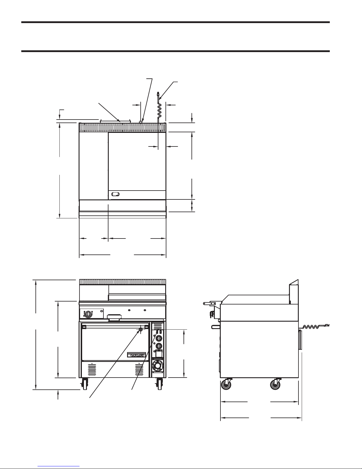
DIMENSIONS
3/4" NPT REAR
GAS INLET
10' POWER CORD
AT REAR [120V]
FAN
GUARD
10 1/2"
[267mm]
1 1/2"
[38mm]
3 3/4" [95mm]
3 1/2"
[83mm]
39 1/2"
[1003mm]
28"
[711mm]
5"
[127mm]
12"
[305mm]
24"
[610mm]
36"
[915mm]
45 1/2"
[1156mm]
31 3/4"
[806mm]
5"
[127mm]
20 1/2"
[521mm]
3/4" NPT REAR
GAS INLET
10' POWER CORD
AT REAR
32 1/2"
[825mm]
34"
[864mm]
4517957 Rev. 2 (06/05)Page 4
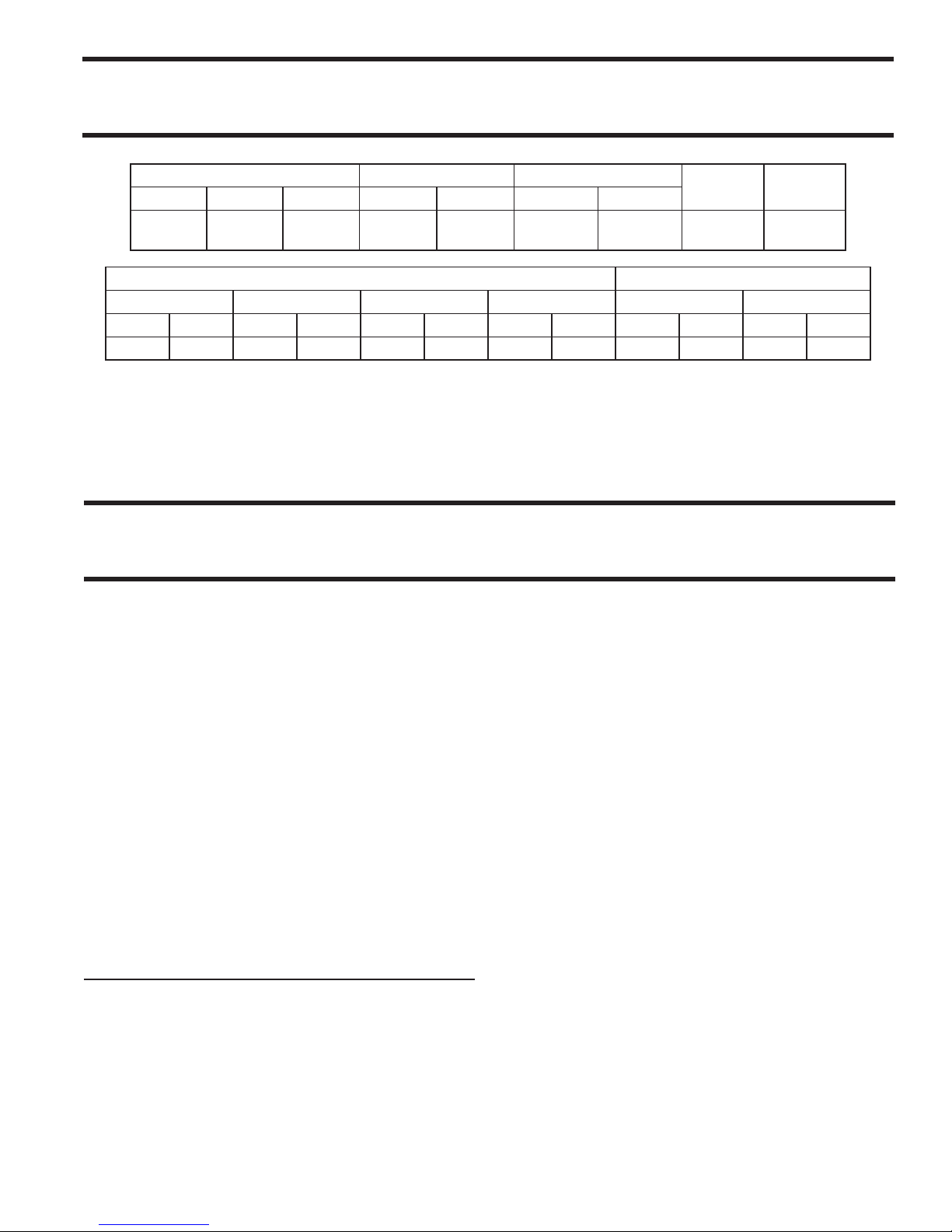
SPECIFICATIONS
Oven Interior Dimensions Entry Clearance Installation Clearances
Height Width Depth Crated Uncrated Sides Rear
13-12"
(343mm)
Hot Top Griddle Oven Total Natural Propane
BTU kW BTU kW BTU kW BTU KW "WC mbar "WC mbar
25,000 7.32 50,000 14.65 30,000 8.79 105,000 30.76 4.5 11 10 25
NOTE: Installation clearance reductions are applicable only where local codes permit.
is product is not approved for residential use.
Commercial cooking equipment requires an adequate ventilation system. For additional information, refer to the National Fire Protection Association's standard NFPA96.
26-1/4"
(667mm)
22"
(559mm)
Input Ratings Operating Pressure
43"
(1105mm)
37-7/8"
(648mm)7"(178mm)6"(152mm)
Shipping
Weight
584lbs.
(265kg)
INTRODUCTION
is equipment must be installed and adjusted by a
competent person in accordance with the law. Failure
to install appliances correctly could lead to prosecution.
It is in your own interests and that of safety to ensure
that the law is complied with. Your Garland Dealer is
well qualified to provide this service.
is appliance should be given regular care and
maintenance. Periodic inspections by the dealer or a
qualified service company are recommended to check
temperature, burner adjustments and to ensure moving
parts are operative. Wherever possible avoid overheating
idle equipment as this is the primary cause of increased
service cost.
“Regular maintenance ensures peak performance.”
Unpacking:
1. Check crate for possible damage sustained during
transit. Carefully remove unit from crate and again
check for damage. Any damage to the appliance
must be reported to the carrier immediately.
2. e wires for retaining the burners and other
packing material must be removed from units. Any
protective material covering stainless steel parts
must also be removed.
3. All ranges are shipped from the factory with casters
fitted.
4. e type of gas and the supply pressure that the
equipment was set up for at the factory is noted on
the data plate and on the packaging. is type of
gas supply must be used.
5. Do not remove permanently affixed labels, warnings
or data plates from the appliance, for this may
invalidate the manufacturer’s warranty.
NOTE: Many parts of the equipment are raw steel i.e
griddle top and solid hot top and can react with moisture
forming rust. is is normal and not considered a defect.
Clean with a stainless steel fiber pad. A light coating of
salt free oil may be applied to prevent further rusting.
Manifold
Inlet Size
3/4" NPT
Female
4517957 Rev. 2 (06/05) Page 5

INTRODUCTION continued
Rating Plate
All burner input ratings are shown on the name/rating
plate of each range which can be located behind the lower
front kick panel, (located below oven door). To access,
remove two () fasteners securing the panel shut.
For proper operation, the fuel information on the data
plate of your new equipment must match your fuel
supply.
When corresponding with the factory or equipment
dealer regarding service problems or replacement parts,
be sure to refer to the particular unit by the correct
model number, including prefix and suffix letters and
numbers and serial number. e rating plate affixed to
the unit contains this information.
Safety
It is essential that the instructions in this booklet are
strictly followed for the safe and economical operation
of the equipment. If it is known or suspected that a fault
exists on the appliance then it must not be used until
the fault is rectified by a competent person.
Power Failure Note: In the event of a power failure, no
attempt should be made to operate the oven. e oven
is gas operated but has electrical features, motor and
door switches.
Product Usage
e top of the range is designed for flexibility and the
preparation of numerous types of products.
Preparation of soups, stocks and sauces are done on a
hot top where slow even cooking is desirable. Heating
larger quantities of food can be done more efficiently than
heating small quantities. Pots and pans should be covered
whenever possible to reduce energy consumption.
High acid sauces, such as tomato should be cooked in
stainless steel vessels rather than aluminum since stainless
will not react chemically. Light coloured sauces may be
dicoloured by the aluminum especially if stirred with
a metal spoon. Salty water may pit aluminum vessels if
used frequently.
INSTALLATION
General Information
Before assembly and connection, check gas supply.
• e type of gas for which the unit is equipped is
stamped on the name/rating plate. Connect a unit
stamped “NAT” only to natural gas, and a unit
stamped “PRO” only to propane.
• In a new installation, have the gas authorities check
meter size and piping to ensure that the gas supply
will deliver sufficient pressure to operate the unit
properly.
• When adding or replacing equipment, have gas
authorities check gas pressure to ensure that the
existing meter and piping will supply fuel to the
appliance with no more than 0.5 inch water column
pressure drop during operation
• Before turning on the main gas supply, check the
unit to be certain that all the controls are in the
“OFF” position.
• When checking gas pressure, be sure that all other
equipment on the same gas line is turned “ON.”
A preset gas pressure regulator is supplied with
GARLAND Restaurant Series Equipment. It may
be necessary to adjust the regulator to deliver fuel at
the pressure shown on the rating plate.
4517957 Rev. 2 (06/05)Page 6
INSTALLATION continued
• In Canada, the installation must comply with local
codes, or in the absence of local codes, with the
Installation Codes for Gas Burning Appliances and
Equipment CAN/CGA-B149.1 and CAN/CGA
B149.2, (latest edition), and with the Canadian
Electrical Code C22.1 (latest edition).
In the United States the installation must comply
with the National Fuel Gas Code ANSI Z223.1,
(latest edition), NFPA No. 54, (latest edition), and
the National Electrical Code ANSI/NFPA 70,
(latest edition), and/or local codes to ensure a safe
and efficient operation.
• is equipment must be electrically grounded in
accordance with local codes, or in the absence of
local codes, with National Electrical Code, ANSI/
NFPA 70, or the Canadian Electrical Code, CSA
C22.2, as applicable.
• e appliance and its individual shut-off (supplied
by others) must be disconnected from the gas
supply piping system during any pressure testing of
the system at pressures in excess of 1/2 PSIG (3.45
KPA). e appliance must be isolated from the gas
supply piping by closing its individual manual shutoff (supplied by others) during any pressure testing
of the gas supply piping system at test pressures equal
to or less than 1/2 PSIG (3.45 KPA).
• Adequate clearance must be provided for servicing
and proper operation.
Clearances
Minimum installation clearance to adjacent combustible
walls and type of floor or base:
MINIMUM CLEARANCES STW286A
LOCATION CLEARANCE
Left Hand Side 7" (178mm)
Right Hand Side 7" (178mm)
Rear 6" (152mm)
TYPE OF FLOOR OR BASE
Combustible
Location
e range should be installed on a firm, smooth and
level floor designed to withstand the weight of the fully
laden appliance. Any openings in the wall beside the
appliance should be sealed.
Appliances Equipped with Casters
• e installation shall be made with a connector
that complies with the Standard for Connectors
for Moveable Gas Appliances, ANSI Z21.69/CGA
6.16, (latest edition), addenda Z21.69a-1989, and
a quick-disconnect device that complies with the
Standard for Quick Disconnects for Use with Gas
Fuel, ANSI Z21.41/CAN1 6.9, (latest edition).
• e front casters on the appliance are equipped
with brakes to limit the movement of the appliance
without placing any strain on the connector or
quick disconnect device or its associated piping.
• Be aware; required restraint is attached to a bracket,
which is located on the rear caster closest to the
gas connection. If disconnection of the restraint is
necessary, be sure to reconnect the device after the
appliance is returned to its original position.
Ventilation & Air Supply
e area in which the appliance is installed must be
adequately ventilated to provide air for combustion,
removal of products of combustion and removal of
steam, etc. Proper ventilation is essential for optimum
performance.
e ideal method of ventilating equipment is the use
of a properly designed canopy which should extend six
inches, (mm), beyond all sides of the appliance(s) and
six feet, six inches, (mm), above the floor.
A strong exhaust will create a vacuum in the room. For
an exhaust vent to work properly, replacement air must
enter the room. e amount of air that enters must equal
the amount exhausted. All gas burners and pilots need
sufficient air to operate. Large objects should not be
placed in front of the appliance(s) which would obstruct
the flow of air into the front.
4517957 Rev. 2 (06/05) Page 7
INSTALLATION continued
Gas Connection:
e gas pipe connection is made at the rear right hand
side of the equipment. e size of the pipe work supplying
the appliance must not be less than the inlet connection
TABLE A. Gas Flow Rate (total)
NATURAL GAS ( ft3/h ) PROPANE GAS (ft3/h )
105 42
TABLE B. Heat Input Per Burner
BURNER
GRIDDLE
HOT TOP
OVEN
kW BTU/HR MJ/HR kW BTU/HR MJ/HR
7.32 25,000 26.37 7.32 25,000
7.32 25,000 26.37 7.32 25,000
8.79 30,000 31.65 8.79 30,000
NATURAL GAS PROPANE
TABLE C. Manifold Pressure / Injector Size
NATURAL GAS PROPANE
BURNER
GRIDDLE
HOT TOP
OVEN
Manifold Pressure Injector Size Manifold Pressure Injector Size
mbar "W.C. DMS mm mbar "W.C. DMS mm
11.2 4.5 42 2.4 25 10 53 1.51
11.2 4.5 41 2.45 25 10 — 1.5
11.2 4.5 35 2.8 25 10 51 1.7
which is /” NPT. An isolating valve is recommended
to be close to the appliance to allow shut down during
an emergency or routine servicing. After installation, the
complete pipe work must be checked for soundness.
NOMINAL HEAT INPUT
26.37
26.37
31.65
NOTE: e pressure must be measured at the pressure test nipple located on the main manifold, located at the
left hand front of the range where the hot top valve is situated, with all burners lit.
TABLE D. Adjustment Pressure for “MIN” Valve Position (Hot Top section)
NATURAL GAS PROPANE
mbar "w.c. mbar "w.c.
2.0 0.8 4.5 1.8
NOTE: e pressure must be measured at the test nipple located downstream of the gas valve.
TABLE E. Aeration Shutter Setting / Pilot Flame Length
BURNER
OVEN
GRIDDLE
HOT TOP
SHUTTER OPENING
NATURAL GAS PROPANE
mm Ins. mm Ins. mm Ins.
19 0.750 19 0.750 25.4 1
41.3 1.625 41.3 1.625 25.4 1
41.3 1.625 41.3 1.625 12.5 0.5
PILOT FLAME LENGTH
4517957 Rev. 2 (06/05)Page 8
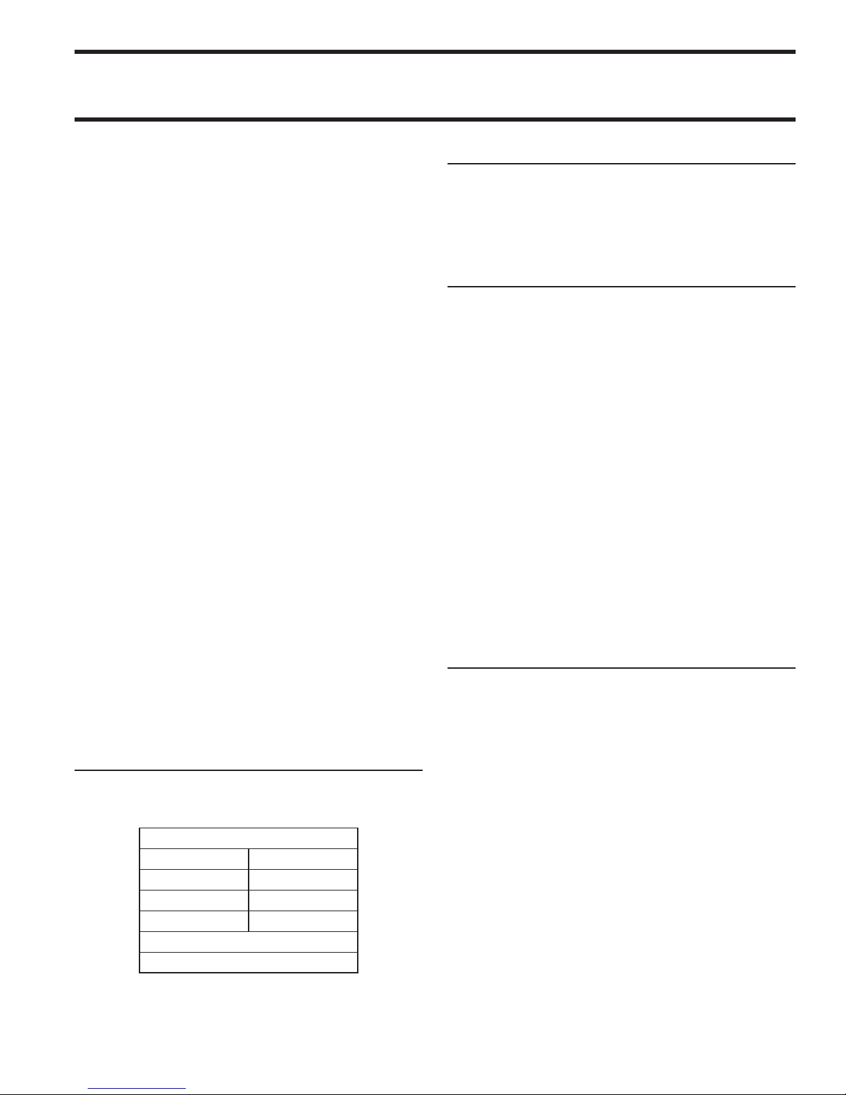
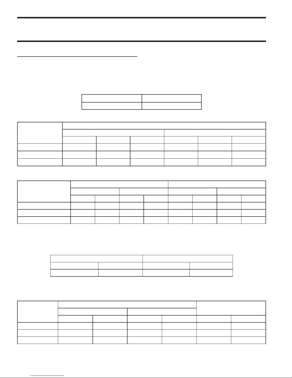
INSTALLATION continued
FIXING SCREW
SHUTTER
OPENING
MEASUREMENT
INJECTOR
LOCATION
TEST POINT
LOW FLAME
ADJUSTER
PILOT
ADJUSTER
SHUTTER
OPENING
MEASUREMENT
Commissioning:
e whole of the gas installation, including the meter,
should be inspected, purged and tested for leakage in
accordance with local codes.
1. Ensure that all controls are in the off position and
turn on the main gas supply and electrical mains.
2. Remove the screws securing the front fascia and
connect a U-gauge manometer to the pressure test
point on the main manifold. Operate the main
burners in accordance with the instructions given
in the User’s manual.
3. Check that the setting pressure is correct per
TABLE C on the previous page. If necessary, adjust
the pressure governor located at the rear of the
range, downstream of the shut-off valve, to give the
required setting.
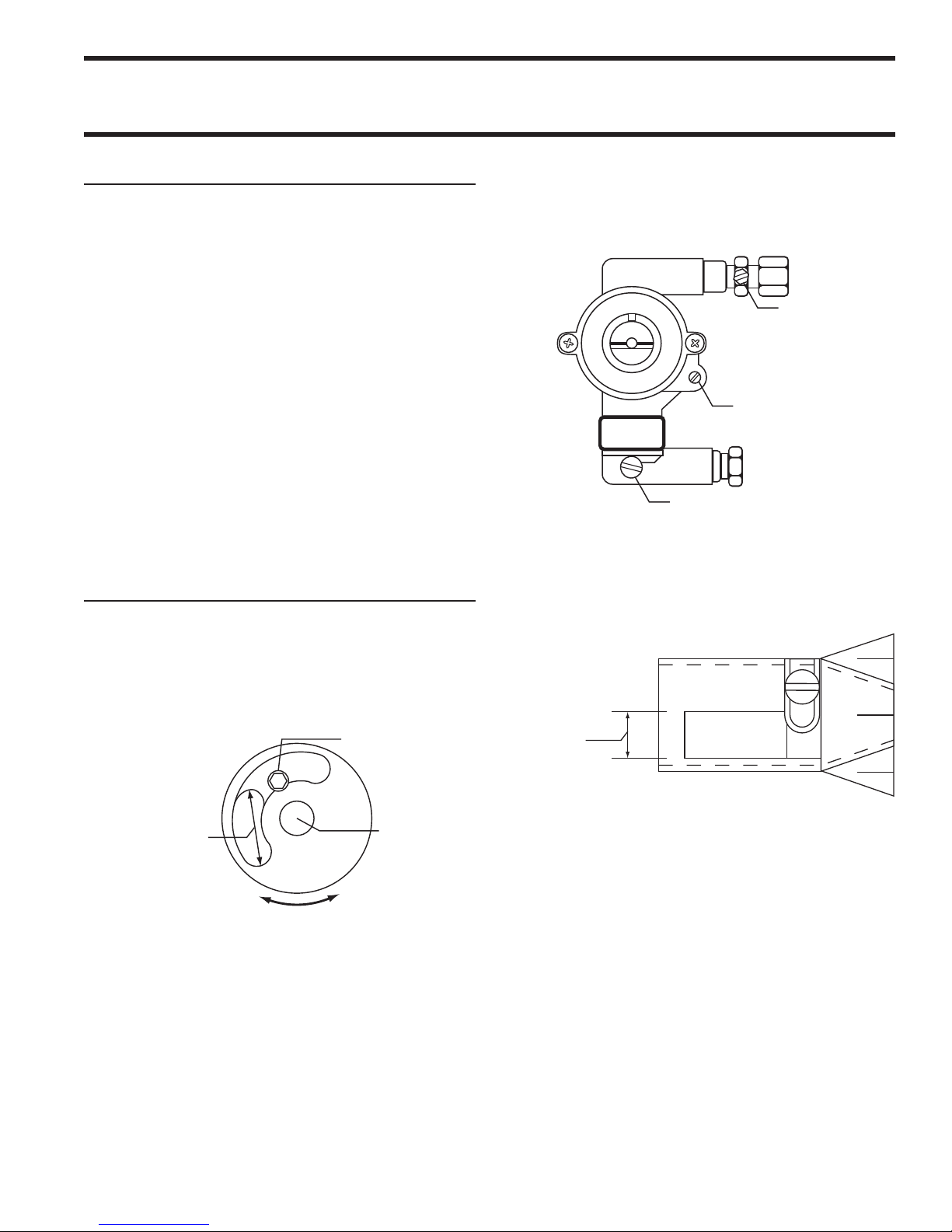
Burner Adjustments:
Griddle /Solid Hot Top Burner
3. With a flat screwdriver, turn the adjuster on the
body of the tap clockwise to reduce the pressure or
anti-clockwise to increase pressure. Set the pressure
to correspond with table D.
Oven Burner
1. Check that the aeration shutter is set to the required
opening per table E. Adjust if necessary.
Check that the aeration shutter is set to provide the
required opening per table E on the previous page. Adjust
if necessary.
Hot Top Minimum Flame Setting
1. Set the gas tap to the MIN position.
2. Connect a U-gauge manometer to the pressure test
nipple located downstream of the gas tap.
When all the settings have been checked, remove the Ugauge manometer, replace the pressure test point screw
and the lower front panel.
Instruct the user or purchaser in the efficient and safe
operation of the appliance.
Tell the user of the location of the gas isolation cock
for use in an emergency. Leave this User Installation
and Servicing Instruction Manual with the user or
purchaser.
4517957 Rev. 2 (06/05) Page 9
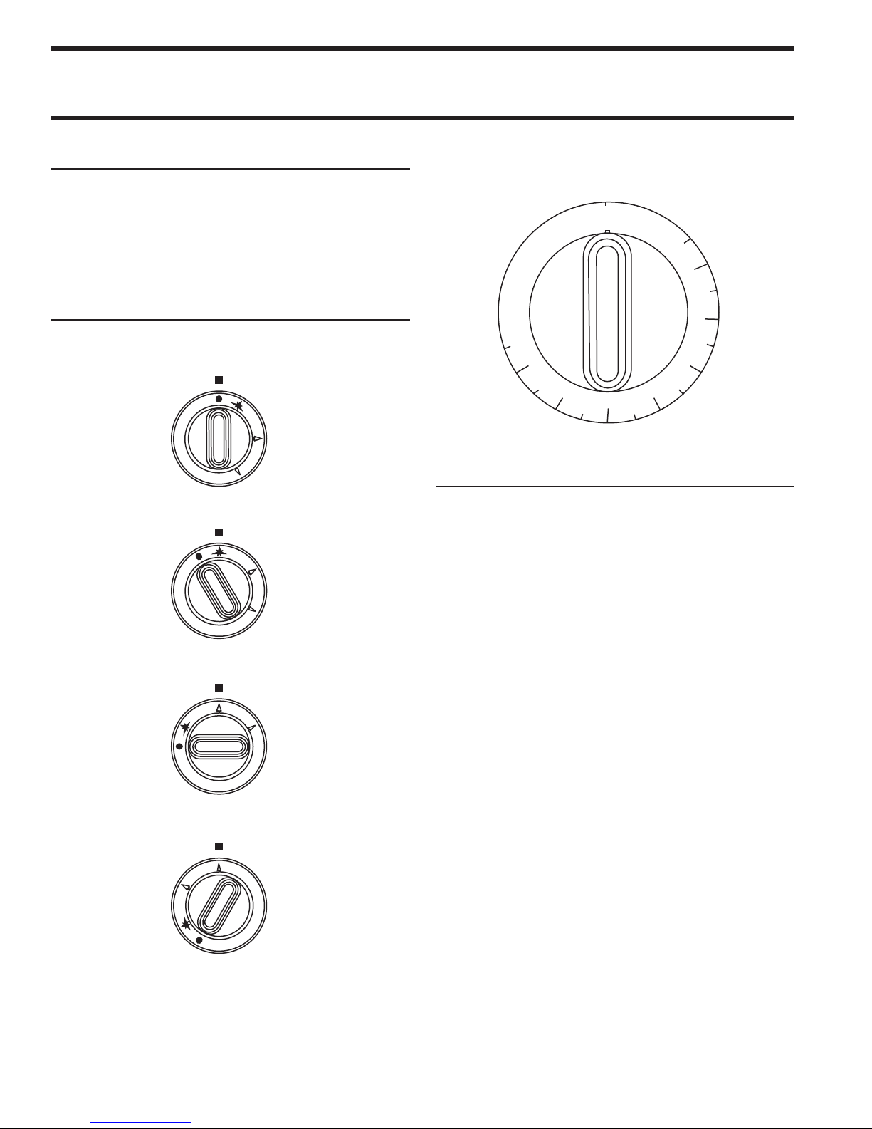
OPERATION
OFF
IGNITION
FULL FLAME
LOW FLAME
SOLID TOP (STW286A)
5
0
0
4
5
0
4
0
0
3
5
0
3
0
0
2
5
0
2
0
0
1
5
0
2
6
2
1
4
4
0
°
F
O
F
F
OVEN/GRIDDLE TOP
Safety concerns
It is the responsibility of the supervisor or equivalent
person to ensure that users of this equipment wear
suitable protective clothing and draw attention to the
fact that some parts will by necessity become very hot
and will cause burns if touched accidentally.
Operation Controls
Griddles
Griddle tops are designed to have food cooked directly
on the surface. Do not put pots or pans on the griddle
surface as this will scratch or nick the surface and will
result in improper cooking or sticking of the product.
Never salt food over the griddle since this will build up
a gummy residue making it difficult to clean.
Avoid hitting the surface of the griddle with the edge of
a spatula since this will cause nicks. e most frequently
used temperatures are ° F (°C) to °(°C).
After one firing, the griddle plate will discolour, this is
normal and will not affect cooking performance.
Check the grease container and drain frequently during
heavy use to prevent overflow.
Preparing A New Griddle
1. Remove the protective coating on the surface using
a mild detergent.
2. oroughly rinse the griddle with vinegar and a
water solution (3/4 cup vinegar per quart of water)
and dry.
4517957 Rev. 2 (06/05)Page 10
 Loading...