

Page 1

INSTALLATION AND
N
I
T
A
T
I
S
T
E
OPERATION MANUAL
GARLAND RTCS TECHNOLOGY BUILT IN
INDUCTION COOKERS,
MODELS: BH/IN 2500, SH/IN 3500,SH/IN 5000,
SH/WO/IN 3500,SH/WO/IN 5000 & SH/WO/IN 8000
I
O
N
A
S
86037
C
CM
L
D
PLEASE READ ALL SECTIONS OF THIS MANUAL
FOR YOUR SAFETY:
DO NOT STORE OR USE GASOLINE
OR OTHER FLAMMABLE VAPORS OR
LIQUIDS IN THE VICINITY OF
THIS OR ANY OTHER
APPLIANCE
WARNING:
IMPROPER INSTALLATION, ADJUSTMENT,
ALTERATION, SERVICE OR MAINTENANCE
CAN CAUSE PROPERTY DAMAGE, INJURY,
OR DEATH. READ THE INSTALLATION,
OPERATING AND MAINTENANCE
INSTRUCTIONS THOROUGHLY
BEFORE INSTALLING OR
SERVICING THIS EQUIPMENT
AND RETAIN FOR FUTURE REFERENCE.
THIS PRODUCT HAS BEEN CERTIFIED AS
COMMERCIAL COOKING EQUIPMENT AND
MUST BE INSTALLED BY PROFESSIONAL
PERSONNEL AS SPECIFIED.
INSTALLATION AND ELECTRICAL CONNECTION
MUST COMPLY WITH CURRENT CODES:
IN CANADA - THE CANADIAN ELECTRICAL
CODE PART 1 AND / OR LOCAL CODES.
IN USA – THE NATIONAL ELECTRICAL CODE
ANSI / NFPA – CURRENT EDITION.
ENSURE ELECTRICAL SUPPLY CONFORMS WITH
ELECTRICAL CHARACTERISTICS SHOWN ON
THE RATING PLATE.
Users are cautioned that maintenance and repairs must be performed by a Garland authorized service agent
using genuine Garland replacement parts. Garland will have no obligation with respect to any product that has been
improperly installed, adjusted, operated or not maintained in accordance with national and local codes or installation
instructions provided with the product, or any product that has its serial number defaced, obliterated or removed,
or which has been modified or repaired using unauthorized parts or by unauthorized service agents.
For a list of authorized service agents, please refer to the Garland web site at http://www.garland-group.com.
The information contained herein, (including design and parts specifications), may be superseded and is subject
to change without notice.
GARLAND COMMERCIAL INDUSTRIES
185 East South Street
Freeland, Pennsylvania 18224
Phone: (570) 636-1000
Fax: (570) 636-3903
Part # 4520898 (03/31/11) © 2005 Garland Commercial Industries, Inc.
Part # 4520898 (03/31/11) Page 1
GARLAND COMMERCIAL RANGES, LTD.
1177 Kamato Road, Mississauga, Ontario L4W 1X4
CANADA
Phone: 905-624-0260
Fax: 905-624-5669
Enodis UK LTD.
Swalloweld Way, Hayes, Middlesex UB3 1DQ ENGLAND
Telephone: 081-561-0433
Fax: 081-848-0041
Page 2

Part # 4520898 (03/31/11)Page 2
Page 3
IMPORTANT INFORMATION
The instructions in this manual are fundamentally important
and must be taken into account during assembly, operation
and maintenance. They must therefore be read very carefully
before installation and operation by the responsible
specialist sta and the operator(s). After installation keep in a
promenade position for consultation and reference.
Warning
Risk of fire or electric
shock
Do not open
Description Of Warning Signs
Identifies safety information
about dangers which may
cause serious personal injury
if equipment is not operated
properly.
Dangerous voltage warning
symbol, indicates a risk of
electric shock and hazards from
dangerous voltage.
Indicates a hazard or unsafe
CAUTION
practice which could result
in minor personal injury or
property damage.
To reduce the risk of fire or electric
shock, do not remove or open cover.
No user Serviceable parts inside.
Refer servicing to qualified personnel.
Warning signs mounted directly on the cooker must be
observed at all times and kept in a fully legible condition
Health Information
WARNING:
This product contains chemicals known
to the State of California to cause cancer.
Installation and servicing of this product
could expose you to airborne particles of
glass wool/ceramic fibers. Inhalation of
airborne particles of glass wool/ceramic
fibers is known to the State of
California to cause cancer.
Electromagnetic field
Part # 4520898 (03/31/11) Page 3
Page 4

Part # 4520898 (03/31/11)Page 4
Page 5

TABLE OF CONTENTS
IMPORTANT INFORMATION. . . . . . . . . . . . . 3
Description Of Warning Signs. . . . . . . . . . . . . . . . . 3
Health Information . . . . . . . . . . . . . . . . . . . . . . . . . . .3
DIMENSIONS AND SPECIFICATIONS . . . . . 6
GENERAL INFORMATION . . . . . . . . . . . . . . . 7
Purpose Of Induction Cookers . . . . . . . . . . . . . . . . 7
Description Of Products . . . . . . . . . . . . . . . . . . . . . . 7
Components Supplied . . . . . . . . . . . . . . . . . . . 7
Product Overview . . . . . . . . . . . . . . . . . . . . . . . . 7
Built In Units At A Glance . . . . . . . . . . . . . . . . . 7
Control knob. . . . . . . . . . . . . . . . . . . . . . . . . . . . . 7
INSTALLATION . . . . . . . . . . . . . . . . . . . . . . . . . 8
Requirements For Installation . . . . . . . . . . . . . . . .8
Electrical Supply . . . . . . . . . . . . . . . . . . . . . . . . . . . . . 8
Electrical installation . . . . . . . . . . . . . . . . . . . . . . . . 19
Operating Test . . . . . . . . . . . . . . . . . . . . . . . . . . . . . . 19
OPERATION. . . . . . . . . . . . . . . . . . . . . . . . . . . 20
Cooking Process . . . . . . . . . . . . . . . . . . . . . . . . . . . .20
Comfort . . . . . . . . . . . . . . . . . . . . . . . . . . . . . . . . . . . .20
Out Of Operation . . . . . . . . . . . . . . . . . . . . . . . . . . .20
Safety Concerns . . . . . . . . . . . . . . . . . . . . . . . . . . . .20
Risk Involved By Disregarding Safety
Information . . . . . . . . . . . . . . . . . . . . . . . . . . . . . 20
Safety Conscious Work . . . . . . . . . . . . . . . . . . 20
Safety Information For The Operator/
Operating Personnel . . . . . . . . . . . . . . . . . . . . 20
Unauthorized Reconstruction And
Use Of Spare Parts. . . . . . . . . . . . . . . . . . . . . . . 21
Improper Operating Methods. . . . . . . . . . . . 21
Pan Detection. . . . . . . . . . . . . . . . . . . . . . . . . . . 21
Ventilation . . . . . . . . . . . . . . . . . . . . . . . . . . . . . . . . . . .8
Cut Out For Model BH/IN 2500 . . . . . . . . . . . . . . .9
Cut Out for Models SH/IN 3500
And SH/IN 5000 . . . . . . . . . . . . . . . . . . . . . . . . . . . . .10
Cut Out For Models SH/WO/IN 3500,
SH/WO/IN 5000 And SH/WO/IN 8000 . . . . . . . . 11
Unit Placement . . . . . . . . . . . . . . . . . . . . . . . . . . . . . 12
Installation of Operating Unit . . . . . . . . . . . . . . . . 12
Fresh Air Intake Installation . . . . . . . . . . . . . . . . . 13
Instructions For Assembly:
Induction Built-In Units . . . . . . . . . . . . . . . . . . . . . .14
Guidelines For Assembly. . . . . . . . . . . . . . . . . 14
Mounting Instructions. . . . . . . . . . . . . . . . . . . 14
Control Of The Heating Area . . . . . . . . . . . . . 21
MAINTENANCE AND CLEANING . . . . . . . . 22
Cleaning . . . . . . . . . . . . . . . . . . . . . . . . . . . . . . . . . . . .22
Maintenance . . . . . . . . . . . . . . . . . . . . . . . . . . . . . . .22
TROUBLESHOOTING . . . . . . . . . . . . . . . . . . 22
Malfunction With Error Code . . . . . . . . . . . . . . . .23
Malfunction Without Error Code . . . . . . . . . . . . . 24
Part # 4520898 (03/31/11) Page 5
Page 6

DIMENSIONS AND SPECIFICATIONS
OPERATING CONDITIONS
Maximum Tolerance of
Supply Voltage
Supply Frequency 50/60 Hz
Protection Class IP XO
Minimal Diameter Of The Pan
(BH/IN and SH/IN)
Maximum Ambient
Temperature
Maximum Relative Humidity
Of Air
ELECTRICAL SPECIFICATIONS
MODEL VOLTAGE Total KW
BH/IN2500 208/230/240 2.5
SH/IN 3500 208/230/240 3.5
SH/IN 5000 208/230/400/440 5.0
SH/WO/IN 3500 208/230/240 3.5
SH/WO/IN 5000 208/230/400/440 5.0
SH/WO/IN 8000 400/440 8.0
Storage -4º to 158ºF (-20º to 70ºC)
Function 41º to 104ºF (5º to 40ºC)
Storage 10%-90%
Function 30%-90%
+6/-10%
4 3/4” (120mm)
DIMENSIONS
Model Glass Ceramic Top Work Surface Measurement
BH/IN 10.24” x 10.24” (260mm x 260mm) 12.20’ x 12.20” (310mm x 310mm)
SH/IN 12.60” X 12.60” (320mm x 320 mm) 15.12” x 15.12” (384mm x 384mm)
SH/WO/IN ø 11.81” (300mm) 15.12” x 15.12” (384mm x 384mm)
Part # 4520898 (03/31/11)Page 6
Page 7
GENERAL INFORMATION
Purpose Of Induction Cookers
The induction cookers are especially suitable as built-in
cookers in closed counters for the preparation of meals. The
cookers can be used for cooking, keeping warm, ambéing,
roasting, etc. of food. Only recommended types and sizes of
pans should be used. Do not use NO NAME pan material but
only pans appropriate for induction cooking!
Description Of Products
Components Supplied
1. Generator with built-in frame including glass top.
2. Operating unit.
Product Overview
Garland supplies several basic types of units with dierent
performances and measurements. Built with a robust
method of construction, they are compact and powerful with
a revolutionary technology in a complete case of CrNi-steel.
Equipped with continuous control, allowing for ecient
cooking and have the following features:
• Simple operation with rotary switch with integrated
mains switch.
• Compact module in a frame design with an induction
generator, controller, coil, ventilator, glass ceramic
cooking zone with power rotary knob and LED-indicator
xed on a CNS plate.
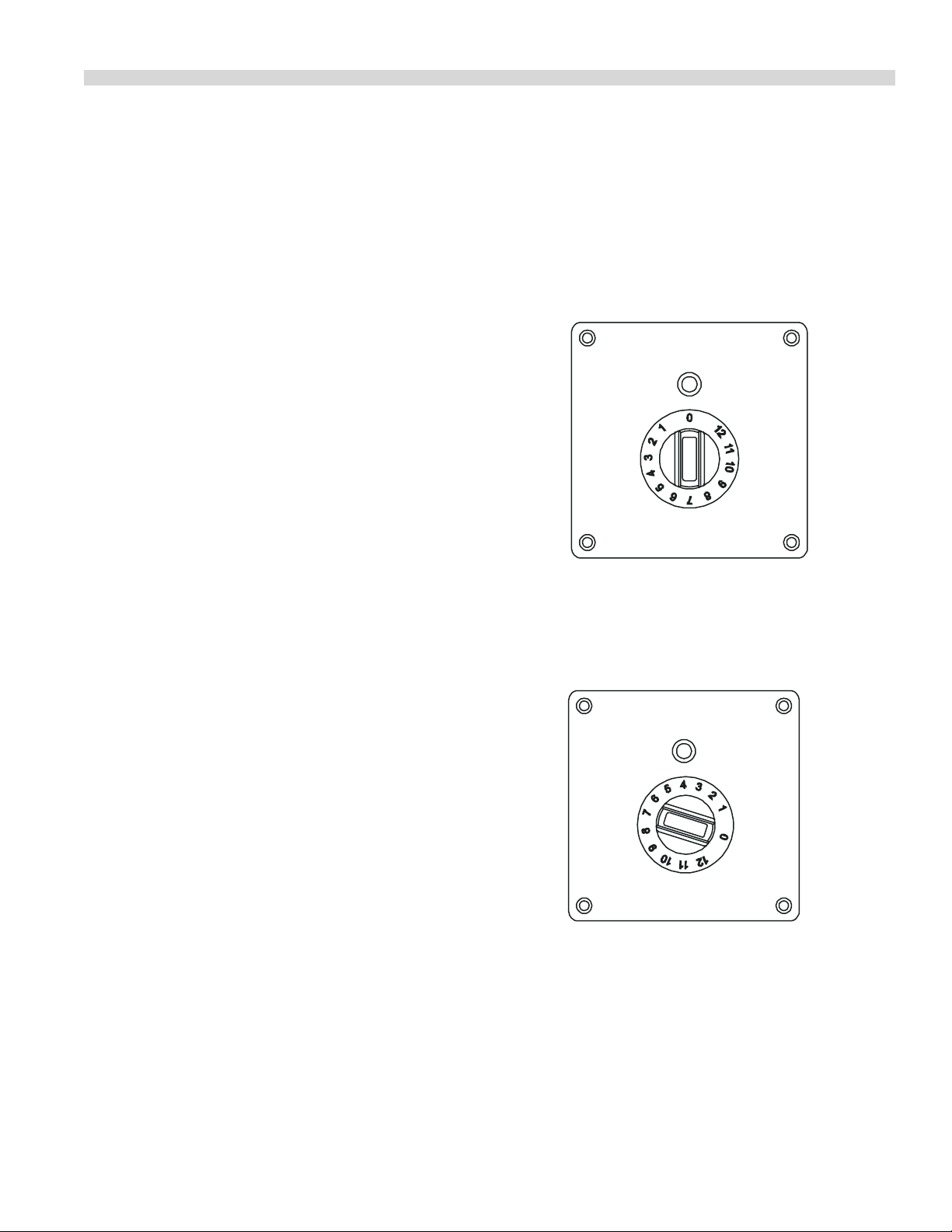
Control knob
The number that points to the operation indicator marks the
actual position of the control knob.
OFF-POSITION
0 Points to the operation indicator
ON-POSITION
Any position when a number other than
0 points to the operation indicator
• Electronic limitation of the connected load.
• Compact powerful electronics enable tight construction
and safe operation.
• A maximum of safety thanks to multiple functions of
protection and checking.
• Short cooking time.
• Compact measurement – light weight.
• Fullls the latest standards: VDE EN 60335-1; -2/36;
CE-conforming UL 197; CAN/CSA/C 22.2 No. 109.
Built In Units At A Glance
Before carrying out function checks, the operator must know
how to operate the cooker.
Part # 4520898 (03/31/11) Page 7
Page 8

INSTALLATION
The generator is delivered with rmly xed built-in frame
including glass top and separate operating unit.
Please note that the unit is
not completely assembled.
CAUTION
Pay close attention to the
requirements for
installation section.
Requirements For Installation
The induction appliance has to be built into a clean and even
surface (table, counter, stove) at a denite place.
Make sure that all installation requirements and instructions
are followed.
Built In appliances must only be installed in closed
counters
The rear side of the induction unit below the fan has to be
absolutely free from obstruction and air intake. Optimal air
intake must not be reduced by the installation. If necessary,
an optional air supply has to be achieved by adding a exible
air duct including a shackle (available as accessory). Be sure
that the air inlet and air outlet openings have a clearance of
at least 1 3/16” (30 mm) from obstructions like walls or oors.
Also ensure that the air of air inlet and air outlet do not mix.
Garland recommends guaranteeing a supply of fresh air by
xing an air duct including shackle or by air openings. The air
exit must not to be hindered by any obstructions.
Electrical Supply
Please observe the following rules:
1. Check and ensure that the supply voltage and the line
current matches the specications given on the rating
plate.
2 This induction appliance is equipped with mains cable
and plug which can be connected to the socket. The
connector must be easily accessible to disconnect the
unit from the electrical supply.
3. When residual current circuit breakers are used, they
must be rated for a breaking current of 30mA or more.
Ventilation
Please read carefully and comply with the following rules.
1. This induction unit is equipped with an internal air
cooling system. Be sure that the air supply and air exhaust
are not blocked (wall, fabric etc.).
2. Ensure that the induction unit does not take in hot
ambient air (concerns units standing side by side, or one
behind the other, or standing near a frying pan or an
oven), otherwise an air duct including shackle has to be
added.
3. The induction unit must not be placed next to an oven or
another heat producing unit.
4. The air intake temperature must be under 104°F (40°C).
5. The operating sta has to make sure that installation,
support and inspection is done by qualied personnel.
Part # 4520898 (03/31/11)Page 8
Page 9

INSTALLATION continued
Cut Out For Model BH/IN 2500
The size of the cut out in the built-in area must be,
11.41” x 11.41” (290 x 290mm), the depth 7.87” (200mm) and
the base at least 13.39” x 11.75” (340 x 273mm).
0.06"
[1.5mm]
Side View of the right
Front view
air exit air exit
6.73"
[171mm]
12.20"
[310mm]
Ventilator
Mains
Cable
11.02"
[280mm]
10.23"
[260mm]
Ceran-surface
air supply
4.06"
[103mm]
10.23"
[260mm]
5.04"
[128mm]
Mounting height
min. 7.87"
[200mm]
Connection
clutch for
operation device
3.07"
[84mm]
11.02"
[280mm]
Required cut-out of the work top
min. 11.42" x 11.42" [290mm x 290mm]
Plug-in clutch for
operation device
7.32"
[186mm]
air supply
12.20"
[310mm]
Part # 4520898 (03/31/11) Page 9
Page 10

INSTALLATION continued
Cut Out for Models
SH/IN 3500 And SH/IN 5000
The size of the cut out in the built-in area must be
13.78” x 13.78” (350 x 350mm), the depth 9.45” (240mm) and
the base at least 16.14” x 13.90” ( 410 x 353mm).
0.06"
[1.5mm]
Air exit
Side view of the right
Ventilator
[143mm]
Air exit
5.63"
Front view
7.13"
[181mm] 8.90"
Plug-in for
operating device
[226mm]
Net cable
15.12"
[384mm]
7.20"
[183mm]
Air Supply
12.99"
[330mm]
12.60"
[320mm]
Ceran-surface
15.12"
[384mm]
12.60"
[320mm]
3.86"
[98mm]
min. 13.78' x 13.78' [350mmx 350mm]
Mounting height
min. 9.45"
[240mm]
Plug type connection
for operating device
13.03"
[331mm]
Required cut-out of the work top
Air supply
Part # 4520898 (03/31/11)Page 10
Page 11

INSTALLATION continued
1
1.
81” (3
0
0M
M
)
WOK-CERAN-BOWL
Air supply
Air exit
0.06”
(1.5mm)
8.46”
(5mm)
Side view of the right
Front view
Net cable
Air exit
7.20”
(183mm)
13.47”
(330mm)
Ventilator
15.12”
(384mm)
15.12”
(384mm)
9.92”
(252mm)
16.69”
(297mm)
3.86”
(98mm)
13.03”
(331mm)
14.31” (363.5mm)
Connection clutch
for operation device
Plug-in clutch
for operation device
Mounting height
min. 11.81”
(300 mm)
Air supply
Required cut-out of the work top
min. 14.49” x 14.49”
(368mm x 368mm)
Cut Out For Models SH/WO/IN
3500, SH/WO/IN 5000 And
SH/WO/IN 8000
The size of the cut out for the built in area must be 14.37” x
14.37” (365 x 365mm), the depth 11.81” (300mm) and the
base at least 16.14” x 13.90” (410 x 353mm).
Part # 4520898 (03/31/11) Page 11
Page 12

INSTALLATION continued
Unit Placement
After the cut out has been made according to the previous
sections, apply silicone to the top of the counter and press
the induction unit into the silicone, allowing for a complete
water tight seal between the unit and the counter. Make sure
the unit is level.
4.09"
[104mm]
4.09"
[104mm]
4.72"
[120mm]
Installation of Operating Unit
Each unit is supplied with a complete operating unit. In order
to x this unit on the surface of the enclosure, a cut out for
the power switch and the LED must considered. The operator
control panel has to be xed vertically on the installation
panel. The cable for the power switch and the LED have a
length of 39.37” (1000mm).
2.24"
[57mm]
3.66"
[93mm]
0"
0.55"
[14mm]
1.73"
0.75"
[19mm]
4.72"
[120mm]
[44mm]
3.66"
[93mm]
4.17"
[106mm]
4.72"
[120mm]
4.72"
[120mm]
1.50"
[38mm]
1.99"
[50.5mm]
0.31"
[8mm]
2.36"
[60mm]
2X ø 0.20"
[ø 5mm]
4.72"
[120mm]
1.10"
[28mm]
4.09"
[104mm]
0.08"
[2mm]
ø 0.33"
[ø 8.5mm]
ø 0.40"
[ø 10.2mm]
4X counter sunk
ø 0.31"x ø 0.18"
[ø 8mm x ø 4.5mm]
4.09"
[104mm]
0.31"
[8mm]
4x R 0.20"[5mm]
Part # 4520898 (03/31/11)Page 12
Page 13

[288.6 mm]
INSTALLATION continued
Figure #
Silicone
Sleeve with hose clip:
mounted on bottom of unit
Sleeve with hose clip:
mounted to cabinet
Air Intake Housing
See Fig. # 2
Cut Out Opening
Louvered
Air Exhaust
Opening
(By Installer)
Aluminum air duct
(Max 96" (8'))
mounted on collars
with hose clamps
Removable grease lter and air
intake housing mounted on
cabinet
Fresh Air Supply
Fresh Air Intake Installation
The built-in induction units require a cooling air intake to
operate eectively. The air intake housing is mounted to
the cabinet, and is tted with a removable stainless steel
grease lter that can be cleaned in a dishwasher. Install the
air intake housing and connect it to the induction unit with
the aluminum air duct. Maximum length of this air inlet is
to be 96” (8’). Make sure the cabinet is also equipped with
a louvered air exhaust having a size of no less than 30 sq
inches (50 sq inches for dual units) for the hot air to escape
(by installer). Failure to provide adequate ventilation for the
unit will result in the unit overheating, nuisance shut down
and potential failure of the unit. (See Figures # 1 & 2)
Figure # - Air Intake Housing
TOP VIEW
11" [279.4mm]
10 3/16" [258.8mm]
8 3/16"
[208 mm]
9"
FRONT VIEW
See Cut out for air intake housing on next page
5/32"
[4mm]
4 Holes
Part # 4520898 (03/31/11) Page 13
Page 14

INSTALLATION continued
Figure Continued - Cut Out
4 HOLES
CUTOUT
9.125" x 7"
[231.8mm x 177.8mm]
Instructions For Assembly:
Induction Built-In Units
Garland has made enhancements for the installation
requirements for the induction cooker built-in models. These
changes are designed to provide the installer with greater
details for installation. Meeting these requirements will
reduce failure due to installation deciencies
NOTE: BI Units not installed correctly will have warranty
Voided.
Guidelines For Assembly
The underside and sides of the induction unit must be
absolutely clear of obstructions to provide for adequate
cooling air to enter and exhaust. Install a exible air duct
including shackle provided with your built-in induction
cooker. Clearances between openings for air supply and air
exhaust to obstacles (walls or oors), must be maintained to
provide clearances of at least 4” (102mm). The outgoing air
must leave without any obstacles. In addition, make sure
that the in-coming and outgoing exhaust air do not mix.
We recommend guaranteeing the supply of fresh air by using
a tube with screens, vent ducts or Air Intake Kit.
It is highly recommend that an exhaust fan be installed
into the cabinet. This will force hot air out the cabinet and
away from the cooker. (See gures # 3, 4 & 5)
The fat and grease lter should be in visible view and
labeled. A blocked grease lter can cause internal damage!
Mounting Instructions
As soon as the above mentioned preparations are made, the
completely pre-mounted induction unit can be installed into
the counter. Apply silicone, which is provided with every air
Intake Kit, completely around the underside of this stainless
steel frame before lowering the induction cooker onto the
counter top. Once the built-in induction cooker is in place,
food save silicone may be also applied completely around
stainless steel top trim, this is highly recommended. Silicone
properly installed, will provide a good seal completely
around the induction cooker and stop moisture from
entering into the cooker. This moisture or grease will cause
damage to the electronic components.
Part # 4520898 (03/31/11)Page 14
Page 15

3
Part # 4520898 (03/31/11) Page 15
Page 16

Figure #
Part # 4520898 (03/31/11)Page 16
Page 17

Figure #
Part # 4520898 (03/31/11) Page 17
Page 18

Figure #
Part # 4520898 (03/31/11)Page 18
Page 19

INSTALLATION continued
Electrical installation
CAUTION
The electrical installation must be done by approved
installation contractors in accordance with specic national
and local codes in conformity with all safety regulations.
The warning signs and rating plates on the appliances must
strictly be followed.
Check and ensure that the supply voltage and the line
current matches the specications given on the rating plate.
Maximum Tolerance of Supply +6/-10 %
1. Turn control knob to o position (“0”).
2. Connect operating unit to the generator.
3. Connect the unit to the power socket (The unit is
delivered completely with mains cable and plug.)
If the voltage is wrong, the
cooker can be damaged.
SPECIFICATIONS
Supply Frequency 50/60 Hz
1 Put some water in the pan and place it in the center of the
heating area.
2. Turn the control knob to an ON position. The indicator
will light up (green) and the water will be heated.
3. Take the pan away from the heating area, the indicator
light will ash.
4. Place the pan back on the heating area, the indicator will
light and the heating process will continue.
5. Turn the control knob in the OFF-position, the heating
process will stop, indicator light turns o.
NOTE: The shining operation indicator light means that
energy is being transferred to the pan. If the operation
indicator light remains o, check the following:
1. Is the cooker connected to the power outlet?
2. Is the control knob in ON position?
3. Did you use a suitable pan (bottom diameter at least 4.72”
(120mm) (only BH/IN and SH/IN), pan made of suitable
material)?
When the installation is complete an operating test outlined
in the below must be done.
Operating Test
Remove all objects from the glass ceramic zone, verify that
this area is neither cracked nor broken. Do not continue
the use when the glass ceramic cooking zone is cracked or
broken, immediately switch it o and disconnect the cooker
from the power outlet and contact a service representative.
The glass ceramic cooking
zone is warmed up from the
CAUTION
heat of the pan. To avoid
injuries (burning) do not
touch this area.
Use a pan suitable for induction cooking, having a bottom
diameter of at least 4.72” (120mm) (only BH/IN and SH/IN).
4. Is the pan placed in the center of the heating area?
To verify, if the pan is suitable, use a permanent magnet and
nd out if it sticks on the bottom of the pan. If not, your pan
is not suitable for induction cooking. Choose a pan which is
recommended for induction cooking. Choose pan material
suitable for induction appliances.
If in spite of all positive controls and tests, the cooker doesn’t
work, refer to the Fault Finding Section, or call a service
representative.
Part # 4520898 (03/31/11) Page 19
Page 20

OPERATION
Cooking Process
The induction cooker is switched on by turning the control
knob (OFF ➯ ON) and it is immediately ready for operation.
The luminous operation indicator light means that energy
is being transferred to the pan. The power rating is set by
turning the control knob. The inductive power depends on
the position of the potentiometer:
Position 1 > minimum power
➯
Position 9 > maximum power (BH/IN only)
➯
Position 12 > maximum power
➯
Due to the following characteristics, the operator must be
more attentive when using the induction cooker than it
would be required with other appliances:
The heat storage capacity of this system is very low. If the
heating level is changed by turning the control knob, the
food is immediately exposed to a dierent temperature.
Do not put empty pans on the cooking zone, rst put
grease or liquid into the pan and start the cooking process
afterwards. Empty pans and pots heat up very quickly. Adjust
the heating level carefully to the required cooking mode.
Set and adjust the power by turning the control knob. The
pan should always remain in the center of the heating area,
otherwise, the bottom of the pan is heated up unequally and
the food inside the pan may burn. When heating up oil or
grease, constantly check the pan to prevent oil and grease
from overheating and burning.
Comfort
The cooker transmits energy only when a pan is placed
on the heating area, independently of the position of the
control knob. If you take the pan away from the heating
area, power transfer to the pan stops immediately. If the pan
is put back on the heating area, the selected power will be
transferred to the pan again.
After switching the cooker to the o position the cooking
process will stop. Except for the pan, no heat is stored.
Out Of Operation
Safety Concerns
Risk Involved By Disregarding Safety Information
Danger for persons, the environment and the cooker as
well as claims for damages of any kind can result from
disregarding safety information. Certain risks may be
associated with disregarding precautions, including:
• Danger to persons through electrical causes.
• Danger to persons through overheated pans.
• Danger to persons through an overheated cooking
platform (ceran glass).
Safety Conscious Work
The safety information pointed out in these instructions,
existing national regulation for the prevention of accidents
as well as any internal working, operating and safety
regulations stipulated by the operator must be observed at
all times.
Safety Information For The
Operator/Operating Personnel
Any risks from electric power must be eliminated. The
cooking induction unit shall only be used if the installation of
the electricity is tted by an approved installation contractor
in accordance with specic national and local codes.
The following safety precautions should be followed at all
times:
• The heating area is warmed up from the heat of the pan.
To avoid injuries (burning) do not touch the heating area.
• To avoid overheating of pans due to the evaporation of
the content, don’t leave pans unattended.
• Switch the control knob o if you take the pan away for
a while. This will avoid the heating process to continue
automatically when a pan is placed back on the heating
area. So, if any person starts to use the cooker, he/she will
have to start the heating process by turning the control
knob in the ON-position.
If the cooker is not in use make sure that the control knob is
in the “OFF” position. If you don’t use the cooker for a long
period (several days), unplug the unit. Make sure that no
liquid can enter into the cooker, do not clean the cooker with
a jet of water.
• Do not insert any piece of paper, cardboard, cloth, etc.
between the pan and the heating area, as this might
initiate a re.
Part # 4520898 (03/31/11)Page 20
Page 21

OPERATION continued
• Since metallic objects are heated up very quickly when
placed on the heating area, do not place any other
objects (closed cans, aluminium foil, cutlery, jewelry,
watches etc.) on the induction cooker.
• Persons with a pacemaker should consult their doctor
whether they are safe near an induction cooker.
• Aluminium foil and plastic vessels must not be placed on
the hot surface.
• The surface must not be used for storage.
• Do not place credit cards, phone cards, cassette tapes, or
other objects sensitive to magnetism on the Ceran glass.
• The induction cooker has an internal air-cooling system.
Do not obstruct the air inlet- and air outlet-slots with
objects (cloth). This would cause overheating and
therefore the cooker would switch o.
• Avoid liquid entering into the cooker. Do not let water or
food overow the pan. Do not clean the cooker with a jet
of water.
• If the heating area (Ceran glass) is cracked or broken, the
induction cooker must be switched o and disconnected
from the electric connection. Don’t touch any parts inside
the cooker.
Unauthorized Reconstruction
And Use Of Spare Parts
Reconstruction of the cooker or changes to the cooker are
not allowed. Contact the manufacturer if you intend to
make any changes on the cooker. To guarantee safety, use
only genuine spare parts and accessories authorized by the
manufacturer. The use of other components will void all
warranty.
Improper Operating Methods
The operating reliability of the cookers can only be
guaranteed by careful use.
Pan Detection
Pans having a diameter less than 4.72” (120 mm) are not
detected (only BH/IN and SH/IN). During pan detection, the
indicator operation ashes. No power is transferred and
the indicator lamp ashes if no pan or an unsuitable pan is
detected.
Control Of The Heating Area
The heating area is controlled by a temperature sensor.
Overheated pans (hot oil, empty pans) can be detected.
Energy transfer will be stopped. The induction unit must be
re-started after it has cooled down.
• If the supply cord is damaged, it must be replaced by the
manufacturer, the service agent or a similarly qualied
person in order to avoid a hazard.
Part # 4520898 (03/31/11) Page 21
Page 22

MAINTENANCE AND CLEANING
NOTE: ensure no liquid can enter the induction unit, do
not clean the cooker with a jet of water.
Cleaning
Slight soiling, no burned residues
Wipe with a moist cloth (scotch), without a cleaning
agent.
Sticky soiling
Remove with a scraper, then wipe the heating area with a
moist cloth.
Lime deposits, caused by water which has boiled over
These spots can be removed with vinegar or a special
cleaning agent.
Sugar, sugar containing food, plastic, aluminum foil
1. Immediately scrape o the sugar, plastic or aluminum foil
residues thoroughly from the hot cooking area, e.g. with
a razor blade.
2. After removal of the residues, clean unit with a cleaning
agent.
3. If the heating area soiled with residues of sugar, plastic
or aluminum foil cools down without prior cleaning, the
ceramic surface might become deformed by pinheadsized pits.
Ceran glass
1. The cleaning of the Ceran glass is identical to other
similar surfaces like glass. Do not use corrosive or abrasive
cleaning agents, such as grill- and oven-sprays, stain- and
rust-removers, scouring powder and rough sponges.
2. Before being cleaned, the Ceran glass must have cooled
down.
Maintenance
Other maintenance and servicing work other than cleaning
as described here, must be done by authorized service
personnel.
A good maintenance of the induction cooker requires a
regular cleaning, care and servicing. The operator has to
ensure, that all components relevant for safety are in perfect
working order at all times.
The cooker should be examined at least once a year by an
authorized technician.
Do not open the cooker,
CAUTION
dangerous electric voltage
inside..
The cookers may only be opened by authorized personnel.
TROUBLESHOOTING
The cookers may only be opened by authorized service
personnel.
Do not open the cooker,
CAUTION
dangerous electric voltage
inside.
NOTE: Stop any actions if the heating area (Ceran glass) is
cracked or broken. The induction cooker must be switched
o and disconnected from the electric supply. Don’t touch
any parts inside the cooker.
Part # 4520898 (03/31/11)Page 22
Page 23

TROUBLESHOOTING continued
Malfunction With Error Code
Number of Flashing
Signals (Code)
E03
- . . . - . . .
E04
- . . . . - . . . .
E06
- . . . . . . - . . . . . .
E07
- . . . . . . . - . . . . . . .
E08
- . . . . . . . . - . . . . . . . .
Order of error message: The indicator lamp lights up for an interval of 0.6 sec. The number of the following short ashes has to be
counted and informs about the kind of error corresponding to the above mentioned code system.
Possible Cause Action To Take By Operator Or Operating
Personnel
Overheated heat sink Let unit cool down
Check air lter and air ow
Air-cooling system obstructed Verify that air inlet and air outlet are not
obstructed with objects
Clean air lter
Overheated cooking zone Let unit cool down
Check air lter and air ow
Overheated electronic Let unit cool down
Check air lter and air ow
Ambient temperature too high (the cooling
system is not able to keep the cooker in normal
operating conditions )
Empty cooking sensing element activated Reset empty cooking protection by switching
Ambient temperature beyond operating range Make sure that the operating conditions
Error on sensing element Contact service agent
Verify that no hot air is sucked in by the fan.
Reduce the ambient temperature. The air inlet
temperature must be lower than 104°F/40°C
the unit o
(especially the ambient temperature) are kept
The code will repeat until the error is cancelled.
The cooling-system (fan) starts to operate when the ambient temperature in the control area exceeds 131°F/55°C. At heat
temperatures higher than 158°F /70°C the controller automatically reduces the power to keep the unit in normal operating
conditions. The cooker runs in a non continuous mode. This mode can be heard.
Part # 4520898 (03/31/11) Page 23
Page 24

TROUBLESHOOTING continued
Malfunction Without Error Code
Fault Possible Cause Action To Take By Operator Or Operating
Personnel
No heating
Operation indicator light
is OFF (dark)
No heating
Operation indicator
light is ashing (If an
error code is ashing see
section “Malfunction with
error code”)
Poor heating
Operation indicator light
is ON (shining)
No reaction to control
knob positions
Heating cycle switches o
and on
Within minutes, fan is
active
Heating cycle switches o
and on
Within minutes, fan is
never active
No mains supply Check the electrical supply (cable plugged
onto the wall socket)
Check preliminary fuses
Control knob is in OFF-position Turn control knob ON
Cooker is defective Ask your supplier for repair service
Unplug the cooker from the mains supply
Pan is too small (bottom diameter less than
4.72” (120mm), only BH/IN and SH/IN)
Pan is not placed in the center of the heating
area (the cooker cannot detect the pan)
Unsuitable pan Choose a pan recommended for induction
Cooker defective Ask your supplier for repair service, unplug the
Used pan is not appropriate Use a pan recommended for induction cooking
Air-cooling system obstructed Verify that air inlet and air outlet are not
Ambient temperature is too high (the cooling
system is not able to keep the cooker in normal
operating conditions )
One phase is missing (only units with three
phase supply)
Cooker defective Ask your supplier for repair service, unplug the
Control knob defective Ask your supplier for repair serviced, unplug
Air inlet or outlet obstructed or fan dirty Remove objects from air inlet and air outlet
Fan defective
Fan control defective
Use a suitable pan
Move the pan to the center of the heating area
cooking
cooker from the mains supply
and compare the result with “your” pan
obstructed with objects
Verify that no hot air is sucked in by the fan.
Reduce the ambient temperature. The air inlet
temperature must be lower than 104°F /40°C.
Check preliminary fuses
cooker from the electrical supply
the cooker from the mains supply
slots, clean the slots
Clean fan
Ask your supplier for repair service
To verify, if the pan is suitable, use a permanent magnet and nd out if it sticks on the bottom of the pan. If not, your pan
is not suitable for induction cooking. Choose a pan which is recommended for induction cooking. Choose pan material
suitable for induction appliances.
The cooling-system (fan) starts to operate when the ambient temperature in the control area exceeds 131°F/55°C. At
heat temperatures higher than 158°F /70°C the controller automatically reduces the power to keep the unit in normal
operating conditions. The cooker runs in a non continuous mode. This mode can be heard.
Part # 4520898 (03/31/11)Page 24
Page 25

TROUBLESHOOTING continued
Fault Possible Cause Action To Take By Operator Or Operating
Personnel
After a long permanent
operating time, the
heating switches o and
on within minutes
Small metallic objects
(e.g. spoon) are heated
up on the cooking area
To verify, if the pan is suitable, use a permanent magnet and nd out if it sticks on the bottom of the pan. If not, your pan
is not suitable for induction cooking. Choose a pan which is recommended for induction cooking. Choose pan material
suitable for induction appliances.
The cooling-system (fan) starts to operate when the ambient temperature in the control area exceeds 131°F/55°C. At
heat temperatures higher than 158°F /70°C the controller automatically reduces the power to keep the unit in normal
operating conditions. The cooker runs in a non continuous mode. This mode can be heard.
Coil overheated, cooking area too hot
Empty pan
Pan with overheated oil
Pan detection circuit is defective Ask your supplier for repair service
Switch cooker o, remove pan and wait until
the cooking area has cooled o
Part # 4520898 (03/31/11) Page 25
Page 26

Part # 4520898 (03/31/11)Page 26
Page 27

Part # 4520898 (03/31/11) Page 27
Page 28

 Loading...