

Garland SHGRIN5000 Installation And Operation Manual
INSTALLATION AND
OPERATION MANUAL
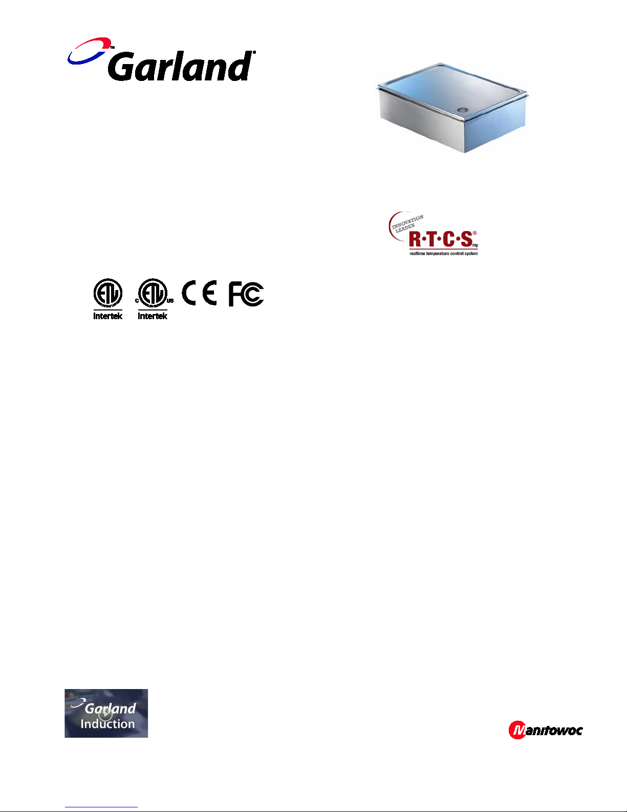
GARLAND INDUCTION
BUILT-IN GRIDDLES
with RTCSmp TECHNOLOGY
Real-time Temperature Control System
multi-point sensing
CE models comply with the latest European
Norms:
EN 60335-1, EN 60335-2-36, EN 62233 (EMC/EMV)
North American models: ETL listed in
compliance with UL 197, CSA C22.2 No.109, NSF-4
Complies with FCC part 18, ICES-001
FOR YOUR SAFETY
DO NOT STORE OR USE GASOLINE OR OTHER
FLAMMABLE VAPORS OR LIQUIDS IN THE VICINITY
OF THIS OR ANY OTHER APPLIANCE
CAUTION
A SUITABLE GREASE-COLLECTING MEANS MUST BE
IN PLACE BEFORE OPERATING APPLIANCE
Models:
SHGRIN3500
SHGRIN5000
PLEASE READ ALL SECTIONS OF THIS MANUAL AND
RETAIN FOR FUTURE REFERENCE.
THIS PRODUCT HAS BEEN CERTIFIED AS COMMERCIAL
COOKING EQUIPMENT AND MUST BE INSTALLED BY
PROFESSIONAL PERSONNEL AS SPECIFIED
INSTALLATION AND ELECTRICAL CONNECTION MUST
COMPLY WITH CURRENT CODES:
IN CANADA – THE CANADIAN ELECTRICAL CODE PART 1
AND / OR LOCAL CODES.
IN USA – THE NATIONAL ELECTRICAL CODE ANSI / NFPA
– CURRENT EDITION.
WARNING
IMPROPER INSTALLATION, ADJUSTMENT, ALTERATION,
SERVICE OR MAINTENANCE CAN CAUSE PROPERTY
DAMAGE, INJURY, OR DEATH. READ THE INSTALLATION,
OPERATING AND MAINTENANCE INSTRUCTIONS
THOROUGHLY BEFORE INSTALLING OR SERVICING THIS
EQUIPMENT
Users are cautioned that maintenance and repairs must be performed by a Garland authorized service agent using only genuine
Garland replacement parts. Garland will have no obligation with respect to any product that has been improperly installed,
adjusted, operated or not maintained in accordance with national and local codes and/or installation instructions provided with
the product or any product that has its serial number defaced, obliterated or removed, and/or which has been modified or
repaired using unauthorized parts or by unauthorized service agents. For a list of authorized service agents and/or genuine
replacement parts, please visit our website at www.garland-group.com for USA and Canada. For international customers, please
visit www.manitowocfoodservice.com. The information contained herein, including design and part specifications, may be
superseded and is subject to change without notice.
Visit our Video Gallery at
Part # 4532291 Rev 2 (01/15/14) © 2013 Garland Commercial Ranges Limited
www.Garland-Group.com
Installation and Operation Manual Garland RTCSmp Induction Built-in Griddles
Warning
WARRANTY
Our warranty statements for induction products are available on-line. Please visit our
website at www.garland-group.com/minisite/service to download the latest revision. If you
might have any questions, please contact Garland.
USING THIS MANUAL
This manual contains important information regarding safety, installation, operation,
maintenance, and troubleshooting. They must be read entirely and carefully by the
installers and operators before the equipment is installed and taken into operation. This
manual must always be available for reference at the place of operation.
Throughout this manual, the induction unit type “RTCSmp Griddle-Line” is referred to as
“induction unit”.
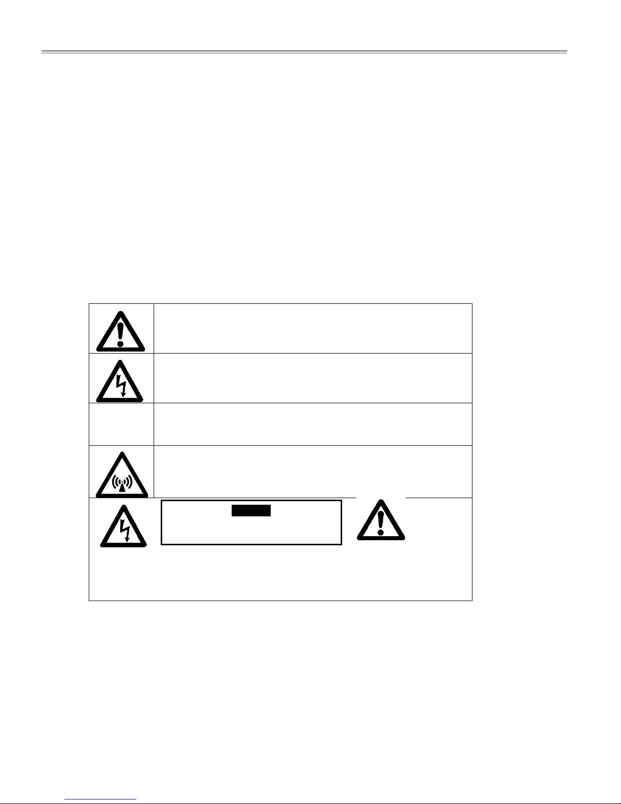
DESCRIPTION OF WARNING SYMBOLS
This symbol alerts you to a hazardous situation that WILL or COULD
cause serious bodily harm or death. Be alert and implement relevant
safety precautions.
CAUTION
CONTACTS
Garland Commercial Ranges Ltd.
1177 Kamato Road, Mississauga, Ontario, Canada. L4W 1X4
T: 1-905-624-0260 | F: 1-905-624-5669 | www.garland-group.com
USA Sales, Parts and Service 1-800-424-2411
Canadian Sales 1-888-442-7526
Canada or USA Parts/Service 1-800-427-6668
International Sales and Service www.ManitowocFoodservice.com
This dangerous voltage warning symbol indicates a risk of electric shock
and hazards from dangerous voltage.
This symbol alerts a hazardous situation, which if not avoided, COULD
cause minor to moderate personal injury or property damage. The
relevant safety precautions MUST be implemented at all times.
Electromagnetic field.
Risk of fire or electric shock
Do not open
To reduce the risk of fire or electric shock,
do not remove or open cover.
No user serviceable parts inside.
Refer servicing to qualified personnel.
2 Part # 4532291 Rev 2 (01/15/14)

Installation and Operation Manual Garland RTCSmp Induction Built-in Griddles
CONTENTS
WARRANTY ..................................................................................................................................... 2
USING THIS MANUAL ..................................................................................................................... 2
DESCRIPTION OF WARNING SYMBOLS ......................................................................................... 2
CONTACTS ...................................................................................................................................... 2
1 Safety Requirements .............................................................................................................. 4
1.1 Risk Involved By Disregarding Safety Information .................................................................................................. 4
1.2 Safety Instructions for Operator ..................................................................................................................................... 4
1.3 Improper Use of the Equipment ..................................................................................................................................... 5
1.4 Unauthorized Modification and Use of Spare Parts ................................................................................................ 5
2 Components and Features ..................................................................................................... 6
2.1 Application .............................................................................................................................................................................. 6
2.2 Components Included ........................................................................................................................................................ 6
2.3 Features .................................................................................................................................................................................... 6
3 Dimensions and Technical Specifications ............................................................................. 7
3.1 Rating Plate ............................................................................................................................................................................. 7
3.2 Nomenclature and Models ............................................................................................................................................... 7
3.3 Dimensions and Weight ..................................................................................................................................................... 7
3.4 Electrical Specifications ...................................................................................................................................................... 7
3.5 Operating Conditions ......................................................................................................................................................... 8
3.6 Compliances ........................................................................................................................................................................... 8
4 Installation .............................................................................................................................. 9
4.1 Location .................................................................................................................................................................................... 9
4.2 Ventilation ............................................................................................................................................................................... 9
4.3 Grease Chute and Grease Collector .............................................................................................................................10
4.4 Compartment Protection ................................................................................................................................................10
4.5 Dimensions and Installation ...........................................................................................................................................11
4.5.1 Control Unit ...........................................................................................................................................................11
4.5.2 Built-In Griddle Plate Installation ..................................................................................................................12
4.5.2.1 Dimensions of RTCSmp Built-In GI-SH/GR/IN 3500 and 5000 .................................................... 12
4.5.2.2 Drop-In Mounting Instructions ............................................................................................................ 13
4.5.2.3 Flush Mounting Instructions ................................................................................................................ 13
4.5.3 Air Intake Kit Installation ..................................................................................................................................14
4.5.3.1 Components .............................................................................................................................................. 14
4.5.3.2 Installation Steps ...................................................................................................................................... 15
4.6 Electrical Installation .........................................................................................................................................................16
5 Function Test ......................................................................................................................... 17
6 Operating Instructions ......................................................................................................... 18
6.1 Grease Collector ..................................................................................................................................................................18
6.2 Temperature Control and Display ................................................................................................................................18
6.3 Considerations .....................................................................................................................................................................19
6.4 When Unit is Not In Use ...................................................................................................................................................19
7 Cleaning ................................................................................................................................. 20
8 Maintenance .......................................................................................................................... 21
9 Important Rules .................................................................................................................... 21
10 Troubleshooting ................................................................................................................... 22
10.1 Common causes for induction unit failure ...............................................................................................................22
10.2 Problems and Possible Causes ......................................................................................................................................23
10.3 Troubleshooting with Error Codes (for Service Technicians) ............................................................................24
Part # 4532291 Rev 2 (01/15/14) 3
Safety Requirements Garland RTCSmp Induction Built-in Griddles
1 Safety Requirements
WARNING This product contains chemicals known to the State of California to cause cancer.
Installation and servicing of this product could expose you to airborne particles of glass
wool / ceramic fibers. Inhalation of airborne particles of glass wool / ceramic fibers is
known to the State of California to cause cancer.
IMPORTANT Warning labels mounted directly on the induction unit must be observed at all times and
kept in a fully legible condition.
IMPORTANT To ensure your working environment is safe, you must follow all of the safety instructions
contained in this manual, the existing national regulations for accident prevention with
electrical systems, as well as any relevant company-specific safety instructions.
The induction unit should only be used if and only if the
installation of the electrical system is fitted by an approved
installation contractor in accordance with specific national and
local regulations.
1.1 Risk Involved By Disregarding Safety Information
Disregarding the safety instructions may cause harm to people, the surroundings, and the induction unit. Garland
is not responsible for any damages or personal injury caused by failure to observe the safety requirements. Risks
involved when disregarding safety precautions may include:
• Death or injury caused by electric shock.
• Injury due to burns from contacting overheated cooking surface, housing, or oil and grease.
1.2 Safety Instructions for Operator
Please follow the following rules to avoid personal injuries and property damages:
• Ensure the grease collector is placed correctly under the grease drain spout before operating the unit.
• The griddle plate and the housing are hot when the unit is in use. To avoid burn injuries, do not touch them
when using the induction unit.
• A dirty air filter blocks the fresh air inlet. The Air Inlet Filter should be cleaned at least once a week (dish-
washer safe) or as often as necessary. Wipe the filter dry before putting it back into the unit.
• Ensure no liquid can enter into the induction unit. Do not let water or food overflow the cooking area. Do not
use hoses to clean or power wash the induction unit or its vicinity.
• Persons with a cardiac pacemaker should consult their doctor whether they are safe near an induction unit.
• The induction unit has an internal air-cooling system. Do not block the air intake and exhaust openings with
objects such as containers. Any obstruction to the air intake and exhaust could cause the unit to overheat and
to switch off.
• If the power cord is damaged, have it replaced immediately by an approved service technician.
4 Part # 4532291 Rev 2 (01/15/14)

Safety Requirements Garland RTCSmp Induction Built-in Griddles
• The induction unit must only be used for cooking. Do no put any object other than food on the cooking
surface.
o Never heat cookware on the griddle plate as this could damage the griddle plate.
o Do not leave any object such as paper, cardboard, or cloth on the griddle plate as this might start a
fire.
o Do not place credit cards, phone cards, tapes, or any objects sensitive to magnetism on the
induction unit.
o Metallic objects are heated up very quickly when placed on the induction unit when it is in use. Do
not place any objects such as closed cans, aluminum foil, cutlery, jewelry, or watches on the
induction unit.
o Do not place any vessels made of aluminum or plastics on the cooking surface.
1.3 Improper Use of the Equipment
The reliability of the induction unit can only be guaranteed when it is used properly. The induction unit must
always be operated within the limits provided in the technical specifications. Please refer to section 9 Important
Rules of using induction equipment.
1.4 Unauthorized Modification and Use of Spare Parts
Please contact Garland if you intend to make any changes on the induction unit. For safety reasons, always use
genuine parts and accessories approved by Garland. Any unauthorized modification as well as any installation of
unapproved components will void all warranty.
Part # 4532291 Rev 2 (01/15/14) 5

Components and Features Garland RTCSmp Induction Built-in Griddles
2 Components and Features
2.1 Application
The unique and patented RTCSmp Install Griddle-Line units are specially engineered for cooking a large variety of
food throughout the day. These compact griddles offer numerous great features including fast heat up time,
uniform heat distribution, and precise temperature monitoring across the entire cooking surface. To guarantee
the induction units’ reliability and performance, please observe all safety, installation, and operation requirements
mentioned in this manual.
2.2 Components Included
• 1 RTCSmp Install Griddle-Line Single Griddle with 6-foot (1829mm) cord and plug
• 1 Control Unit with 1 RJ-45 Cable, and 1 Control Panel Overlay
• 1 Mounting Frame (leveling plate and heat resistant silicone gasket included)
• Accessories included: 1 Scrubbing Pad, 1 Griddle Spatula, 1 Griddle Plate Splash Guard
• 1 Air Intake Kit (part number 95000021)
• Installation and Operation Manual
2.3 Features
Built with a robust construction, the RTCSmp Induction Griddles are compact and powerful with a revolutionary
RTCSmp-Technology (Realtime Temperature Control System with Multi-Point sensing). The RTCSmp Technology
monitors the energy supply, the state of the induction coil, power board, CPU, and the cooking zone in realtime.
Please review the following features this induction unit offers:
• Instant energy transmission from inverter coil to griddle plate surface for fast startup. Heat up time, from 68° -
392°F (20° - 200°C): within 4 ½ minutes for the 3500W models; within 3 ½ minutes for the 5000W models.
• Equal heat distribution from corner to corner, with consistent results across the entire cooking surface.
Surface is controlled and monitored with multiple sensors, resulting in instantaneous recovery.
• Durable griddle plate surface with a polished HPCR-INOX coating, which is resistant to abrasion, chemical,
corrosion, and heat.
• Removable: stainless steel griddle plate splash guard and dishwasher-safe air filter.
• Integral cooling fan keeps electronics cool.
• Simple to operate. Adjust the temperature setting simply by turning the knob. The temperature value is
shown via the LED digital display.
• CrNi-steel housing, curvatures and smooth surface enable easy cleaning.
• Patents: Europatent EP 0858722, Swiss patent 695817, US 7183525 B2
6 Part # 4532291 Rev 2 (01/15/14)

Dimensions and Technical Specifications Garland RTCSmp Induction Built-in Griddles
3 Dimensions and Technical Specifications
3.1 Rating Plate
The rating plate lists important information such as model
number, serial number, and electrical specifications. The
rating plate is affixed to the bottom of the unit.
3.2 Nomenclature and Models
Series Function Built-In Power
SH =
Slim Hob
GR =
Griddle Line
IN =
Built-In Line
3.3 Dimensions and Weight
Model
SHGRIN3500 20.91” x 15.35” (531 x 390 mm) 19.41” x 13.86” (493 x 352 mm) 24 kg/ 52.9 lb
SHGRIN5000 20.91” x 15.35” (531 x 390 mm) 19.41” x 13.86” (493 x 352 mm) 25 kg/ 55.1 lb
Dimensions (width x depth) Griddle plate (width x depth) Weight
3.4 Electrical Specifications
Model Voltage Power Plug Configuration
SHGRIN3500 208 V AC / 1Ph / 60Hz 3500 W / 17A
SHGRIN3500 230 V AC / 1Ph / 50Hz 3500 W / 15A
(Watt)
3500
5000
Models
SHGRIN3500
SHGRIN5000
SHGRIN5000 208 V AC / 3Ph / 60Hz 5000 W / 14A
SHGRIN5000 400 V AC / 3Ph / 50Hz 5000 W / 8A
Part # 4532291 Rev 2 (01/15/14) 7

Dimensions and Technical Specifications Garland RTCSmp Induction Built-in Griddles
Maximum Ambient Temperature
In Storage > -4°F to +158°F (-20°C to +70°C)
3.5 Operating Conditions
Max. Tolerance of Nominal Supply Voltage +6 /-10 %
Supply frequency 50/60 Hz
Ingress Protection class IP X0
In Operation >+ 41°F to +104°F (+5°C to +40°C)
Maximum Relative Air Humidity In Storage > 10% to 90%
In Operation > 30% to 90%
Maximum fan air flow: 88.29cfm/150m3 per hour and min. opening: 16.59in2/10700mm2 is required.
3.6 Compliances
• North American models:
ETL listed in compliance with UL 197, CSA C22.2 No.109, NSF-4. Complies with FCC part 18, ICES-001
• CE models comply with the latest European Norms:
EN 60335-1, EN 60335-2-36, EN 62233 (EMC/EMV)
Patents: Europatent EP 0858722, Swiss patent 695817, US 7183525 B2
8 Part # 4532291 Rev 2 (01/15/14)

Installation Garland RTCSmp Induction Built-in Griddles
4 Installation
IMPORTANT
• Kitchen designers and installation contractors are responsible for designing and installing correctly the
appropriate support structures and ventilation system for the cooking equipment.
• When designing kitchen cabinets for the induction equipment, please take into account all installation
requirements, including factors such as: ease of electrical installation, size of the power conductor, and
length of the wires.
• The installation, including electrical installation, must be carried out by registered installation contractors
only. The contractors are responsible for interpreting all instructions correctly and performing the
installation in compliance with national and local regulations. The warning signs and rating plates on the
cooking equipment must strictly be followed.
• Read ALL SECTIONS carefully, comply with all requirements listed and ensure all inspection is done by
qualified personnel.
• Refer to the technical data given in chapter 3 Dimensions and Technical Specifications.
• Induction equipment that is not installed correctly will have warranty voided. See Warranty, p.2.
4.1 Location
• The induction unit must be installed securely in closed counters. IMPORTANT: Allow easy access to the
unit, the air intake duct, and the wiring for maintenance and service.
• The induction unit must be installed securely on a leveled and even counter surface.
• Prevent moisture, hot ambient air or greasy fume being drawn in by the induction unit, especially when
the equipment is installed in the vicinity of any heat-producing equipment (fryer/oven) or high steam
emitting equipment (pasta cookers/steamers/water bath).
• Avoid placing the induction unit on or near any heat producing equipment such as an oven or a deep-
fryer.
• If the induction unit must be installed around a heat-producing unit, ensure the ambient temperature is
below 104°F (40°C). It is highly recommended to install an external fan to remove hot air away from the
induction unit.
• Ensure the cabinet interior is protected against liquid penetration.
• Allow easy access to the control knob and ensure the digital display is not obstructed.
• Keep the induction unit away from combustible materials, vapors or liquids.
4.2 Ventilation
Proper cool air intake and ventilation is essential to the reliability and functioning of the induction unit. Please
ensure all requirements listed below are met:
• This induction unit is equipped with an internal air cooling system. Do not block the air intake and
exhaust outlets.
• The maximum fan air flow is 88.29 cfm (150 m
• An optimal air circulation and air flow must not be restricted by the installation.
Part # 4532291 Rev 2 (01/15/14) 9
2
) is required around the fan.
mm
3
per hour) and a minimal opening of 16.59 sq. in. (10700
 Loading...