

Page 1
INSTALLATION AND
OPERATION MANUAL
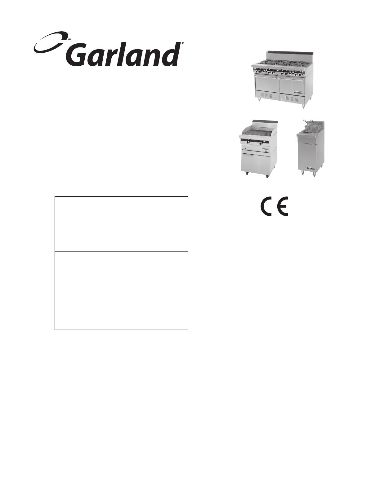
STARFIRE SENTRY SERIES
MEDIUM DUTY RANGES,
FRYERS & BROILERS
FOR YOUR SAFETY:
DO NOT STORE OR USE GASOLINE
OR OTHER FLAMMABLE VAPORS OR
LIQUIDS IN THE VICINITY OF
THIS OR ANY OTHER
APPLIANCE
WARNING:
IMPROPER INSTALLATION, ADJUSTMENT,
ALTERATION, SERVICE OR MAINTENANCE
CAN CAUSE PROPERTY DAMAGE, INJURY,
OR DEATH. READ THE INSTALLATION,
OPERATING AND MAINTENANCE
INSTRUCTIONS THOROUGHLY
BEFORE INSTALLING OR
SERVICING THIS EQUIPMENT
PLEASE READ ALL SECTIONS OF THIS MANUAL
AND RETAIN FOR FUTURE REFERENCE.
THIS PRODUCT HAS BEEN CERTIFIED AS
COMMERCIAL COOKING EQUIPMENT AND
MUST BE INSTALLED BY PROFESSIONAL
PERSONNEL AS SPECIFIED.
For Your Safety:
Post in a prominent location, instructions to be
followed in the event the user smells gas. This
information shall be obtained by consulting
your local gas supplier.
Users are cautioned that maintenance and repairs must be performed by a Garland authorized service agent
using genuine Garland replacement parts. Garland will have no obligation with respect to any product that has been
improperly installed, adjusted, operated or not maintained in accordance with national and local codes or installation
instructions provided with the product, or any product that has its serial number defaced, obliterated or removed,
or which has been modified or repaired using unauthorized parts or by unauthorized service agents.
For a list of authorized service agents, please refer to the Garland web site at http://www.garland-group.com.
The information contained herein, (including design and parts specifications), may be superseded and is subject
to change without notice.
GARLAND COMMERCIAL INDUSTRIES
185 East South Street
Freeland, Pennsylvania 18224
Phone: (570) 636-1000
Fax: (570) 636-3903
Part # 4519070 Rev 1 (12/07) © 2007 Garland Commercial Industries, Inc.
Part # 4519070 Rev 01 (12/07) Page 1
GARLAND COMMERCIAL RANGES, LTD.
1177 Kamato Road, Mississauga, Ontario L4W 1X4
CANADA
Phone: 905-624-0260
Fax: 905-624-5669
Enodis UK LTD.
Swallow eld Way, Hayes, Middlesex UB3 1DQ ENGLAND
Telephone: 081-561-0433
Fax: 081-848-0041
Page 2

Part # 4519070 Rev 01 (12/07)Page 2
Page 3

TABLE OF CONTENTS
TECHNICAL SPECIFICATIONS . . . . . . . . . . . . . . . . . .4
Gas Supply . . . . . . . . . . . . . . . . . . . . . . . . . . . . . . . . . . . . . . 4
Electrical Supply . . . . . . . . . . . . . . . . . . . . . . . . . . . . . . . . . 4
Data Plate Location . . . . . . . . . . . . . . . . . . . . . . . . . . . . . . 4
Table B: Model Designations. . . . . . . . . . . . . . . . . . . . . . 5
Table B Continued . . . . . . . . . . . . . . . . . . . . . . . . . . . . . . . 6
Table C Exterior Dimensions. . . . . . . . . . . . . . . . . . . . . . 6
Table D Gas Flow Rate (Net) Per Model . . . . . . . . . . . . 7
Table E Heat Input (Gross) Per
Burner / Burner Group . . . . . . . . . . . . . . . . . . . . . . . . . . . 7
Table F Pressure Setting / Injector Size . . . . . . . . . . . . 8
Table G Aeration Shutter Setting / Pilot Flame
Length . . . . . . . . . . . . . . . . . . . . . . . . . . . . . . . . . . . . . . . . . . 8
Table H Nominal Gas Consumption &
Injector Sizes Australia Only . . . . . . . . . . . . . . . . . . . . . . 9
Table I Clearances. . . . . . . . . . . . . . . . . . . . . . . . . . . . . . . . 9
STATUTORY REGULATIONS . . . . . . . . . . . . . . . . . . .10
INTRODUCTION. . . . . . . . . . . . . . . . . . . . . . . . . . . . . .10
Uncrating. . . . . . . . . . . . . . . . . . . . . . . . . . . . . . . . . . . . . . . 10
General Information . . . . . . . . . . . . . . . . . . . . . . . . . . . . 10
Service . . . . . . . . . . . . . . . . . . . . . . . . . . . . . . . . . . . . . . . . . 10
Safety . . . . . . . . . . . . . . . . . . . . . . . . . . . . . . . . . . . . . . . . . . 11
Optional Extras . . . . . . . . . . . . . . . . . . . . . . . . . . . . . . . . . 11
INSTALLATION. . . . . . . . . . . . . . . . . . . . . . . . . . . . . . .11
Appliances Equipped with Legs . . . . . . . . . . . . . . . . . 11
Appliances Equipped with Casters . . . . . . . . . . . . . . . 11
Ventilation and Air Supply. . . . . . . . . . . . . . . . . . . . . . . 12
Mounting Instructions for Backguards,
Low Prole Backguards, Single-Deck
High Shelves, Double Deck High Shelves,
Salamanders and Cheesmelters. . . . . . . . . . . . . . . . . . 12
Gas Connections. . . . . . . . . . . . . . . . . . . . . . . . . . . . . . . . 12
Testing and Adjustments . . . . . . . . . . . . . . . . . . . . . . . . 13
Electrical Connection . . . . . . . . . . . . . . . . . . . . . . . . . . . 13
Installation of a Common Front Rail & Backguard 13
Assembly of Broiler . . . . . . . . . . . . . . . . . . . . . . . . . . . . . 14
Sanitary Countertop Seal. . . . . . . . . . . . . . . . . . . . . . . . 14
Assembly of Optional Stands . . . . . . . . . . . . . . . . . . . .14
OPERATING INSTRUCTIONS . . . . . . . . . . . . . . . . . .15
Starre Sentry Ranges. . . . . . . . . . . . . . . . . . . . . . . . . . .15
General Notes . . . . . . . . . . . . . . . . . . . . . . . . . . . . . . . . . . . 15
Open Type Hot Plate . . . . . . . . . . . . . . . . . . . . . . . . . . . . . 15
Solid Hot Tops . . . . . . . . . . . . . . . . . . . . . . . . . . . . . . . . . . . 15
Oven (Standard) . . . . . . . . . . . . . . . . . . . . . . . . . . . . . . . . . 16
“RC” Convection Ovens . . . . . . . . . . . . . . . . . . . . . . . . . . 16
Fryers and Broilers . . . . . . . . . . . . . . . . . . . . . . . . . . . . . . 17
Range-Match Broilers . . . . . . . . . . . . . . . . . . . . . . . . . . . . 17
Range-Match Fryers . . . . . . . . . . . . . . . . . . . . . . . . . . . . . 18
Fryer Burner . . . . . . . . . . . . . . . . . . . . . . . . . . . . . . . . . . . . . 18
PRODUCT APPLICATION INFORMATION . . . . . . .19
General. . . . . . . . . . . . . . . . . . . . . . . . . . . . . . . . . . . . . . . . .19
Open Burners. . . . . . . . . . . . . . . . . . . . . . . . . . . . . . . . . . . 19
Hot Tops. . . . . . . . . . . . . . . . . . . . . . . . . . . . . . . . . . . . . . . . 19
Griddle Tops . . . . . . . . . . . . . . . . . . . . . . . . . . . . . . . . . . . . 19
Oven (Standard) . . . . . . . . . . . . . . . . . . . . . . . . . . . . . . . . 19
Range Base Convection Oven . . . . . . . . . . . . . . . . . . .20
ADJUSTMENTS. . . . . . . . . . . . . . . . . . . . . . . . . . . . . . .21
Pilot Burner Adjustment. . . . . . . . . . . . . . . . . . . . . . . . . 21
“Minimum” Flame Setting . . . . . . . . . . . . . . . . . . . . . . . 21
Burner Gas / Air Adjustment . . . . . . . . . . . . . . . . . . . . . 22
FDO Heavy Duty Oven control. . . . . . . . . . . . . . . . . . . 22
Fryer Thermostat . . . . . . . . . . . . . . . . . . . . . . . . . . . . . . .23
MAINTENANCE AND CLEANING. . . . . . . . . . . . . . .23
Seasoning . . . . . . . . . . . . . . . . . . . . . . . . . . . . . . . . . . . . . . 23
Griddle . . . . . . . . . . . . . . . . . . . . . . . . . . . . . . . . . . . . . . . . . . 23
Cast Iron top Grates. . . . . . . . . . . . . . . . . . . . . . . . . . . . . . 24
Cleaning. . . . . . . . . . . . . . . . . . . . . . . . . . . . . . . . . . . . . . . . 24
Painted Finishes . . . . . . . . . . . . . . . . . . . . . . . . . . . . . . . . . 24
Stainless Steel . . . . . . . . . . . . . . . . . . . . . . . . . . . . . . . . . . . 24
Oven Interior (Porcelain Enamel) . . . . . . . . . . . . . . . . . 24
Griddle . . . . . . . . . . . . . . . . . . . . . . . . . . . . . . . . . . . . . . . . . . 24
Open Top Burners . . . . . . . . . . . . . . . . . . . . . . . . . . . . . . . 25
Cast Iron Top and Ring Grates . . . . . . . . . . . . . . . . . . . . 25
Porcelain Top and Ring Grates. . . . . . . . . . . . . . . . . . . . 25
Hot tops . . . . . . . . . . . . . . . . . . . . . . . . . . . . . . . . . . . . . . . . . 25
CONVERSION INSTRUCTIONS. . . . . . . . . . . . . . . . .26
TROUBLESHOOTING . . . . . . . . . . . . . . . . . . . . . . . . .27
Open Burner – Models not Equipped with
Flame Supervision Device . . . . . . . . . . . . . . . . . . . . . . .27
Open Burner – Models Equipped with
Flame Supervision Device . . . . . . . . . . . . . . . . . . . . . . .27
Oven (Standard & Convection). . . . . . . . . . . . . . . . . . . 28
Convection Ovens Only . . . . . . . . . . . . . . . . . . . . . . . . . 29
Hot Top / Griddle / Broiler . . . . . . . . . . . . . . . . . . . . . . . 30
Fryers . . . . . . . . . . . . . . . . . . . . . . . . . . . . . . . . . . . . . . . . . .31
WIRING DIAGRAMS . . . . . . . . . . . . . . . . . . . . . . . . . .32
Part # 4519070 Rev 01 (12/07) Page 3
Page 4

TECHNICAL SPECIFICATIONS
Gas Supply
The gas pipe connection is made at the rear left hand side
of the equipment. The size of the pipe work supplying the
appliance must not be less than the inlet connection, which
is 3/4” NPT. An isolating cock is recommended to be close to
the appliance to allow shutdown during an emergency or
routine servicing. After installation, be certain to check the
complete pipe work for leakage.
Electrical Supply
An electrical supply of 230VAC, 50Hz is required for all ranges
with sux RC or E.
Data Plate Location
Every cooking unit has a rating plate. All burner input ratings
are shown on the serial plate of each unit model the location
of the plate is indicated in Table A
Table A.
MODEL
WITH SUFFIX
Ranges Behind the lower kick panel
Broilers Behind upper front panel
Fryers Behind cabinet door
Knowing the equipment model is essential if spare parts
are required or for discussing equipment problems with
Garland’s technical support sta. Table B lists the various
models of heavy duty Ranges, Broilers & Fryers in Garland’s
gas operated Starre series.
LOCATION
Part # 4519070 Rev 01 (12/07)Page 4
Page 5
TECHNICAL SPECIFICATIONS continued
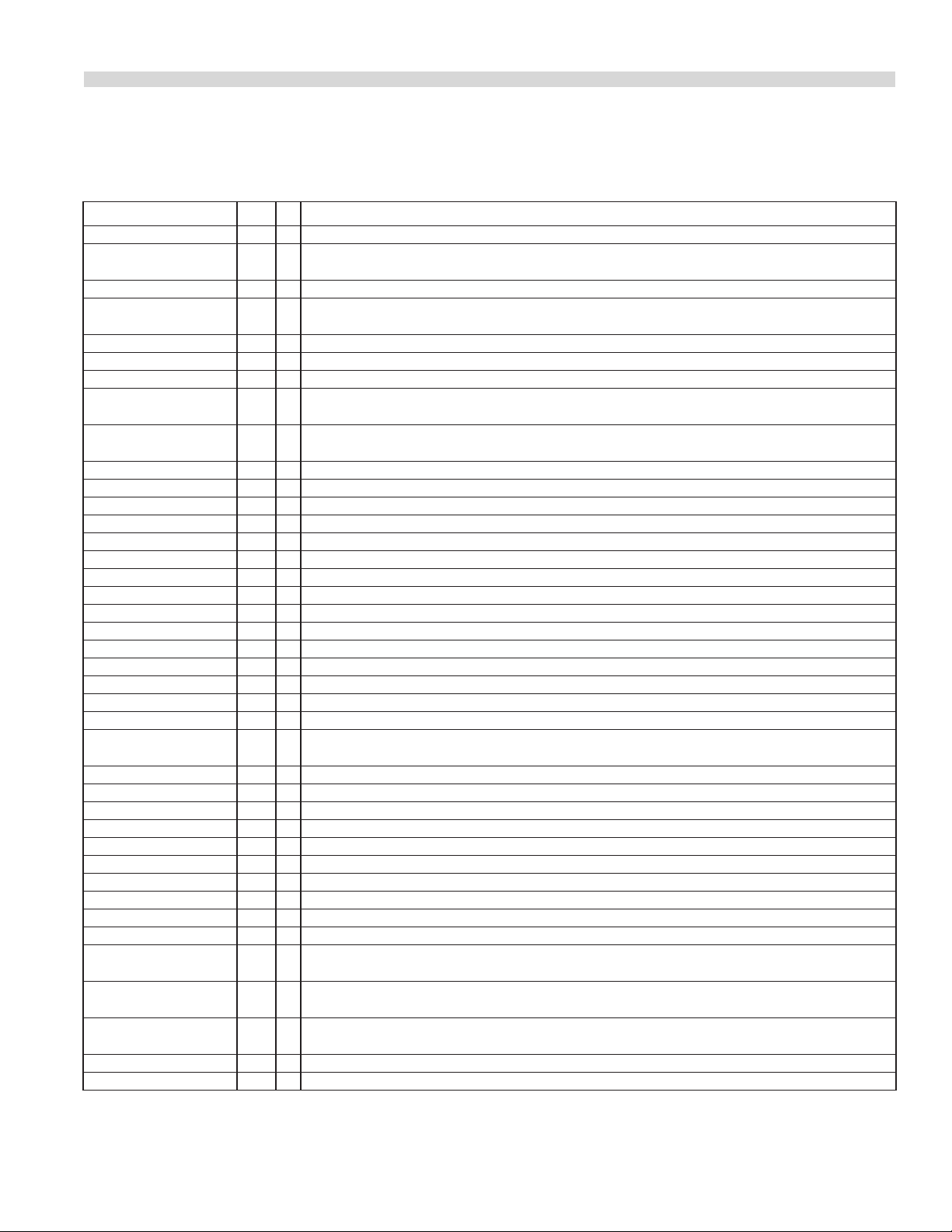
Table B: Model Designations.
MODEL MM DESCRIPTION
S*, ST28(E) 610 24 Range with space saver oven and four equally rated open top burners
S*, ST28(E)-1 610 24
S*, ST28(E)-2 610 24 Range with space saver oven and two 305mm solid hot plate sections
S*, ST28(E)-12G 610 24
S*, ST28(E)-24G 610 24 Range with space saver oven and a 610mm griddle section
S*, ST288(E) 1219 48 Range with two space saver ovens and eight equally rated open top burners
S*, ST288(E)-1 1219 48 Range with two space saver ovens, six open top burners and a 305mm hot plate section
S*, ST288(E)-2 1219 48
S*, ST288(E)-3 1219 48
S*, ST288(E)-4 1219 48 Range with two space saver ovens and four 305mm hot plate sections
S*, ST288(E)-12G 1219 48 Range with two space saver ovens, six open top burners and a 305mm griddle section
S*, ST288(E)-24G 1219 48 Range with two space saver ovens, four open top burners and a 610mm griddle section
S*, ST288(E)-36G 1219 48 Range with two space saver ovens, two open top burners and a 914mm griddle section
S*, ST288(E)-48G 1219 48 Range with two space saver ovens and a 1219mm griddle section
S*, ST288(E)-1-12G 1219 48 Same as S, ST288(E) with a 305mm hot plate and a 305mm griddle section
S*, ST288(E)-2-12G 1219 48 Same as S, ST288(E) with two 305mm hot plate sections and a 305mm griddle section
S*, ST288(E)-1-24G 1219 48 Same as S, ST288(E) with a 305mm hot plate and a 610mm griddle section
S*, ST286(RC)(E) 914 36 Range with oven and six open top burners
S*, ST286(RC)(E)-1 914 36 Range with oven and four open top burners and a 305mm hot plate section
S*, ST286(RC)(E)-2 914 36 Range with oven and two open top burners and two 305mm hot plate sections
S*, ST286(RC)(E)-3 914 36 Range with oven and three 305mm hot plate sections
S*, ST286(RC)(E)-12G 914 36 Range with oven and four open top burners and a 305mm griddle section
S*, ST286(RC)(E)-24G 914 36 Range with oven and two open top burners and a 610mm griddle section
S*, ST286(RC)(E)-36G 914 36 Range with oven and a 914mm griddle section
S*, ST286(RC)(E)-1-12G 914 36
S*, ST284(RC)(E) 1524 60 Range with two ovens and ten open top burners
S*, ST284(RC)(E)-1 1524 60 Range with two ovens, eight open top burners and one 305mm hot plate section
S*, ST284(RC)(E)-2 1524 60 Range with two ovens, six open top burners and two 305mm hot plate sections
S*, ST284(RC)(E)-3 1524 60 Range with two ovens, four open top burners and three 305mm hot plate sections
S*, ST284(RC)(E)-4 1524 60 Range with two ovens, two open top burners and four 305mm hot plate sections
S*, ST284(RC)(E)-5 1524 60 Range with two ovens and ve 305mm hot plate sections
S*, ST284(RC)(E)-12G 1524 60 Range with two ovens, eight open top burners and one 305mm griddle section
S*, ST284(RC)(E)-24G 1524 60 Range with two ovens, six open top burners and one 610mm griddle section
S*, ST284(RC)(E)-36G 1524 60 Range with two ovens, four open top burners and one 914mm griddle section
S*, ST284(RC)(E)-48G 1524 60 Range with two ovens, two open top burners and one 1219mm griddle section
S*, ST284(RC)(E)-1-12G 1524 60
S*, ST284(RC)(E)-1-24G 1524 60
S*, ST284(RC)(E)-1-36G 1524 60
S*, ST282(RC)(E) 1524 60 Range with single oven, Storage compartment with raised broiler/griddle
S*, ST283(RC, RC2)(E) 1524 60 Range with two ovens with a raised griddle/broiler
Range with space saver oven, two equally rated open burners
and a 305mm wide solid hot plate
Range with space saver oven, two equally rated open top burners and a 305mm griddle
section
Range with two space saver ovens, four open top burners and two 305mm hot plate
sections
Range with two space saver ovens, two open top burners and three 305mm
hot plate sections
Range with oven and two open top burners, one 305mm hot plate section
and one 305mm griddle
Range with two ovens, six open top burners and one 305mm hot plate and
a 305mm griddle
Range with two ovens, four open top burners and one 305mm hot plate and
a 610mm griddle
Range with two ovens, two open top burners and one 305mm hot plate and
a 914mm griddle
* S Prex are not CE marked
TableB continued on next page
Part # 4519070 Rev 01 (12/07) Page 5
Page 6
TECHNICAL SPECIFICATIONS continued
Table B Continued
MODEL MM DESCRIPTION
S*, ST280-45R(E) 914 36 Range with oven and front red hot top
S*, ST280-45T(E) 914 36 Modular top range with front red hot top
S*, ST280-45S(E) 914 36 Range with S, STorage cabinet base and front red hot top
S*, ST280-18B 457 18 Char broiler with three burners
S*, ST280-24B 610 24 Char broiler with four burners
S*, ST280-36B 914 36 Char broiler with six burners
S35-280S, ST 406 16 Deep fat fryer
S35-280SD 406 16 Deep fat fryer with Stainless Steel fry pot
S35-280SC 406 16 Deep fat fryer with Stainless Steel fry pot and cabinet
ST24GS 610 24 Grill/Salamder (Grillmander) with three burners
* S Prex are not CE marked
SUFFIX DEFINITIONS FOR MODELS
E Electric spark pilot ignition R Range with standard oven
B Broiler ST Fryer with standard fry pot
T Modular top section SD Fryer with stainless steel fry pot
S Storage cabinet under top section SC Fryer with S/S fry pot and cabinet
RC Range with convection oven GS Grill/Salamander
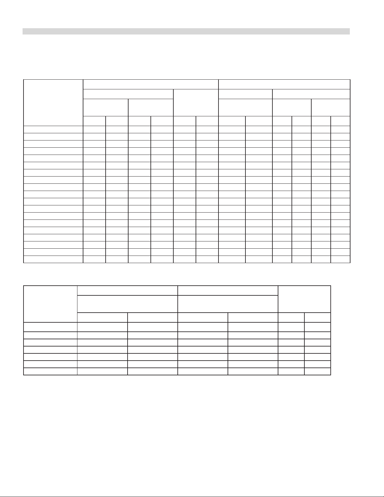
Table C Exterior Dimensions
MODELS
S, ST28 1137 44.75 610 24 876 34.5 168* 370*
S, ST286 1137 44.75 914 36 876 34.5 191* 420*
S, ST288 1137 44.75 1220 48 876 34.5 304* 670*
S, ST284 1137 44.75 1524 60 876 34.5 318* 700*
S, ST287 1137 44.75 1524 60 876 34.5 318* 700*
S, ST280-45R 1137 44.75 914 36 876 34.5 200 450
S, ST280-45S 1137 44.75 914 36 876 34.5 175 400
S, ST280-45T 216 8.5 914 36 876 34.5 136 300
S, ST282 1137 44.75 1524 60 876 34.5 386 850
S, ST283 1137 44.75 1524 60 876 34.5 386 850
S, ST280-18B 1137 44.75 457 18 876 34.5 102 225
S, ST280-24B 1137 44.75 610 24 876 34.5 120 265
S, ST280-30B 1137 44.75 762 30 876 34.5 132 290
S, ST280-36B 1137 44.75 915 36 876 34.5 148 325
S35-280(ST,SD,SC) 1137 44.75 407 16 876 34.5 82 180
ST24GS 555 21.83 610 24 876 34.5 162 365
* Add 9.1kg (20lbs) for each 305mm (12”) section of hot plate or griddle that replaces an open top section
NOTE: Height dimensions are specied with 4” (101.6mm) legs. Add 2” (50.8mm) for 6” legs
HEIGHT WIDTH DEPTH WEIGHT
mm ins. mm ins. mm ins. kg lb
Part # 4519070 Rev 01 (12/07)Page 6
Page 7
TECHNICAL SPECIFICATIONS continued
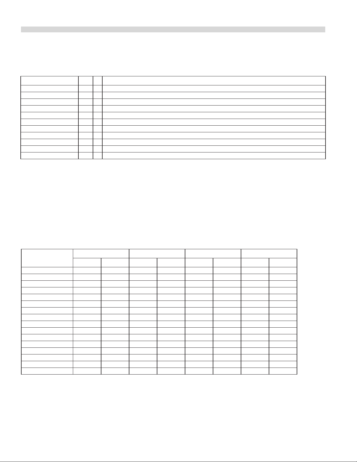
Table D Gas Flow Rate (Net) Per Model
MODEL
ST28 3.38* 3.93* 2.14*
ST288 6.8* 7.9* 4.28*
ST286 4.86* 5.65* 2.97*
ST284 8.37* 9.74* 5.53*
ST280-45R 2.9 3.4 1.9
ST280-45S 2.1 2.4 1.5
ST280-45T 2.1 2.4 1.5
ST282 5.94* 6.9* 4.12*
ST283 6.78* 7.88* 4.62*
ST280-18B 1.26 1.46 0.94
ST280-24B 1.67 1.95 1.26
ST280-30B 2.09 2.43 1.57
ST280-36B 2.51 2.92 1.9
S35-280(ST,SD,SC) 3.07 3.57 2.3
* Deduct 0.83 m3/h (G20), 0.96 m3/h (25) & 0.62 kg/h (G31) from the totals shown above
when a 305mm hot plate or griddle section replaces a two-burner section of open top
G20 @ 20mbar G25 @ 25mbar G31 @ 37/50mbar
2nd Family (m3/h) NET 3rd Family (kg/h)
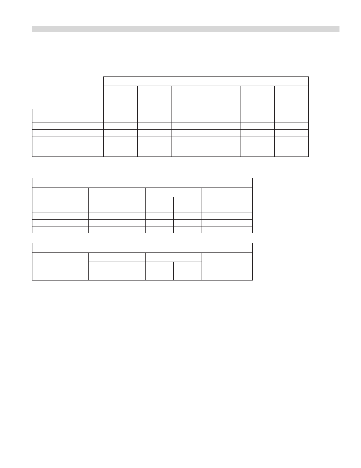
Table E Heat Input (Gross) Per Burner / Burner Group
2nd Family, Groups H,L & E 3rd Family, Group 3P
MODELS / SECTION
ST280 Oven 8.79 30,000 31.65 6.45 30,000 31.65
ST28 & 288 Oven 7.33 25,000 26.4 6.45 22,000 23
Open Top Burner 7.03 24,000 25.32 5.86 20,000 20.92
Griddle / Hot Plate 5.3 18,000 18.99 5.3 18,000 18.83
ST280-18B 13.2 45,000 47.47 13.2 45,000 47.47
ST280-24B 17.6 60,000 63.3 17.6 60,000 63.3
ST280-30B 22 75,000 79.11 22 75,000 79.11
ST280-36B 26.4 90,000 94.94 26.4 90,000 94.94
S35-280(ST,SC,SD) 32.2 110,000 116.04 32.2 110,000 116.04
ST280-45R Target Top 10.84 37,000 39 10.25 35,000 36.9
ST283 Raised Grill 3.81 13,000 13.71 3.81 13,000 13.71
(G20/G25 @ 20/25 mbar) NAT (G31 @ 37/50 mbar) PROPANE
Per burner / section Per burner / section
kW BTU/HR MJ/HR kW BTU/HR MJ/HR
Part # 4519070 Rev 01 (12/07) Page 7
Page 8
TECHNICAL SPECIFICATIONS continued
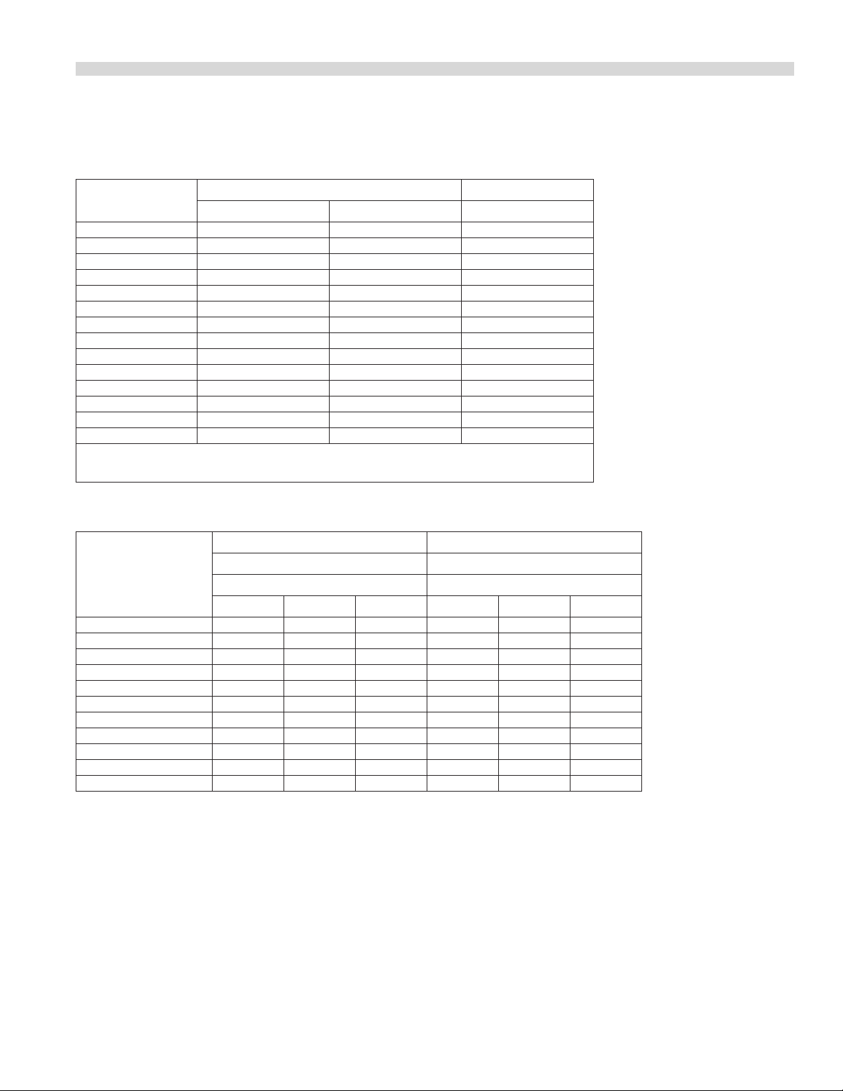
Table F Pressure Setting / Injector Size
2nd Family, Groups H, L & E 3rd Family, Group 3P
Setting Pressure
MODEL/SECTION
ST28(E) 11.2 4.5 15.6 6.4 - - 25 10 - - - ST288(E) 11.2 4.5 15.6 6.4 - - 25 10 - - - ST286(RC)(E) 11.2 4.5 15.6 6.4 - - 25 10 - - - ST284(RC)(E) 11.2 4.5 15.6 6.4 - - 25 10 - - - ST28(E) Oven - - - - 39 2.5 - - 53 1.5 53 1.5
ST288(E) Oven - - - - 39 2.5 - - 53 1.5 53 1.5
ST286(E) Oven - - - - 31 3.05 - - 53 1.5 53 1.5
ST284(E) Oven - - - - 31 3.05 - - 53 1.5 53 1.5
Open Top Burner - - - - 42 2.35 - - 55 1.3 55 1.3
Hot Plate / Griddle - - - - 47 2 - - 1.2 1.2 1.2 1.2
ST280-18B 20 8 25 10 1.5 1.5 37/50 14.8/20 1 1 63 0.95
ST280-24B 20 8 25 10 1.5 1.5 37/50 14.8/20 1 1 63 0.95
ST280-30B 20 8 25 10 1.5 1.5 37/50 14.8/20 1 1 63 0.95
ST280-36B 20 8 25 10 1.5 1.5 37/50 14.8/20 1 1 63 0.95
S35-280(ST, SC, SD) 10.5 4.2 - - 1.7 1.7 22.4 9 1 1 1 1
ST280-45 R, S, T 11.2 4.5 15.6 6.4 - - 25 10 - - - Oven - - - - 3.8 2.5 - - 53 1.4 54 1.4
ST280-45 Hot Top - - - - 53 1.55 - - 61 1 61 1
ST283 Raised Grill 11.2 4.5 15.6 6.4 53 1.55 25 10 59 1.05 59 1.05
G20 @ 20 mbar G25 & 25 mbar
mbar “W.C. mbar “W.C. DMS mm mbar “W.C. DMS mm DMS mm
Injector Size
Setting Pressure Injector Size
G31 @ 37/50
mbar
37 mbar 50 mbar
Table G Aeration Shutter Setting / Pilot Flame Length
2nd Family, Groups H, L & E 3rd Family, Group 3P
SECTION
Oven 16 0.625 19 0.75 12.5 0.5
Open Burner 16 0.625 16 0.625 12.5 0.5
Griddle / Hot Plate 25.4 1 27 1.062 12.5 0.5
ST280 Broiler 25.4 1 25.4 1 12.5 0.5
Fryer N/A N/A N/A N/A 24.5 1
ST280-45 Top 38 1.5 31.75 1.75 12.5 0.5
ST283 Raised Grill 16.4 0.65 21.4 0.85 25.4 1
G20/G25 @ 20/25 mbar Natural
Gas
mm Ins. mm Ins. mm Ins.
G31 @ 37/50 mbar Propane
Pilot Flame
Length
Part # 4519070 Rev 01 (12/07)Page 8
Page 9
TECHNICAL SPECIFICATIONS continued
Table H Nominal Gas Consumption & Injector Sizes Australia Only
NATURAL GAS PROPANE GAS
INJ. DIA
mm
ST28 Oven 2.35 26.4 1 1.3 26.4 2.49
ST280 Oven 2.64 31.65 1 1.61 31.65 2.49
Open Top 2.26 21.1 1 1.32 21.1 2.49
Hot Plate / Griddle 2.05 18.98 1 1.18 18.98 2.49
ST280 Broiler 1.9 18.5 1 1.1 16.95 2.49
ST280-45 Top 1.6 39 1 1 39 2.49
ST283/ST24GS Raised Grill 1.8 13.7 1 1.05 13.7 2.49
MJ/H
GAS
PRESSURE
(kPa)
INJ. DIA.
Mm
MJ/H
Table I Clearances
CLEARANCE FROM COMBUSTIBLE CONSTRUCTION
MODEL
Ranges 150 6 150 6 Combustible
Broilers 150 6 150 6 Combustible
Fryers 150 6 150 6 Combustible
ST280-45T 150 6 150 6 Non-Combustible
SIDES REAR
mm Ins. mm Ins.
BASE
GAS
PRESSURE
(kPa)
CLEARANCE FROM NON-COMBUSTIBLE CONSTRUCTION
MODEL
All Models 0 0 0 0 Non-Combustible
SIDES REAR
mm Ins. mm Ins.
BASE
Part # 4519070 Rev 01 (12/07) Page 9
Page 10

STATUTORY REGULATIONS
The installation of this appliance must be carried out by
a competent person and in accordance with the relevant
regulations, standards, codes of practice and the related
publications of the Country of destination.
INTRODUCTION
It is required by law that all gas appliances are installed by
competent persons in accordance with the LOCAL GAS
SAFETY REGULATIONS. Failure to install appliances correctly
can lead to prosecution. It is in your own interests and that of
safety to insure that there is compliance with the law.
We suggest installation, maintenance and repairs should be
performed by your local authorized service agency listed in
your information manual pamphlet.
The following instructions should be read carefully as the
manufacturer cannot be held responsible for any damage
to property, persons or animals caused by incorrect
installation or operation of the appliance.
AUSTRALIA SPECIFIC CLAUSE
This appliance must be installed in accordance with the
manufacturers instructions, local gas tting regulations
and requirements of AS 5601 / AG 601 installation code.
All burner adjustments and settings should be made by a
qualied gas technician.
3. Have a qualied gas technician check the gas pressure
to make certain that the existing gas facilities, (meter,
piping, etc.), will deliver the volume, (BTU’s), of gas
required for proper operation with no more than 0.50”
WC (0.12 kPa/12.5 mbar) pressure drop. When checking
pressure, be sure that all the equipment on the same gas
line is turned to the “ON” position.
4. Make certain that new piping, joints and connections
have been made in a clean manner, and have been
purged, so that the piping compound, chips, etc., will
not clog pilots, valves, and/or controls. Use pipe joint
sealant that is approved for use with natural and liqueed
petroleum gases.
Uncrating
Check crate for possible damage sustained during transit.
Carefully remove the unit from the crate and again check for
damage. Any damage to the appliance must be reported to
the carrier immediately.
General Information
1. The correct type of gas for which the unit was
manufactured is noted on the rating plate, and only this
type of gas must be used.
2. The gas pressure must be checked when the unit is
installed to ensure that the operating gas pressure is the
same as that specied on the rating plate. If necessary,
pressure adjustments may be made at the pressure
regulator, supplied on each appliance.
5. WARNING: Check gas connections for leaks using soap
solutions or similar mean. DO NOT CHECK WITH AN OPEN
FLAME.
Service
When corresponding with the factory or your local
authorized service agency regarding service or parts, be sure
to refer to the particular unit by the correct model number
(including prex and sux letters and numbers) and the
serial or code number. The rating plate axed to the unit
contains this information. Rating Plate locations are listed in
Table A.
In the event you have any questions concerning the
installation, use, care or service of the product, write or call
our Product Service Department.
This product has been certied as commercial cooking
equipment and must be installed by professional personnel
as specied.
Part # 4519070 Rev 01 (12/07)Page 10
Page 11

INTRODUCTION continued
Safety
IF YOU SMELL GAS
1. Turn o the appliance at the gas inlet cock and open all
doors and windows.
2. Do not operate any electrical switches and extinguish all
naked ames.
3. Contact the local gas authority immediately.
WARNING: do not store ammable materials in or near this
appliance.
INSTALLATION
Do not store or use gasoline or other ammable vapors and
liquids in the vicinity of this or any other appliance.
Do not spray aerosols in the vicinity of this appliance while it
is in operation.
Optional Extras
• Pot rack
• Spreader plate
• Common front rail & back guard
• End unit
• Casters
1. Carefully remove unit from carton. The wires or ties
retaining the burners and other packing material must be
removed from the unit. Any protective material covering
stainless steel parts must also be removed.
2. All equipment is shipped from the factory with legs
tted, unless otherwise specied. Where the range is to
be mounted on a dais or cove base, it is shipped without
legs. Legs must be tted to the oven where it is installed
on a combustible oor.
3. The back splash or optional pot rack is packed separately.
4. The type of gas and supply pressure that the equipment
was set up for at the factory is noted on the data plate
and on the packaging. This type of gas supply must be
used.
5. Before assembly and connection, check gas supply.
6. Adequate clearance must be provided for servicing and
proper operation.
7. Do not remove permanently axed labels, warning or
data plates from the appliance, for this may void the
manufacturer’s warranty.
Appliances Equipped with Legs
Raise the front of the appliance and block. Do not lay the
appliance on its back. Position a leg insert in leg retainer
opening and tap upward until the insert seats at the collar
ange. Repeat leg insert installation for the other three
legs and adjust all four legs to the same height. Legs can be
further adjusted to level the appliance and to compensate
for uneven ooring.
Appliances Equipped with Casters
A. The installation shall be made with a connector that
complies with the Standard for Connectors for Moveable
Gas Appliances, ANSI Z21.69/CSA 6.16, Addenda
Z21.69B-2006/CSA 6.16B-2006 (or latest edition), and a
quick-disconnect device that complies with the Standard
for Quick Disconnects for Use with Gas Fuel, ANSI Z21.41/
CSA 6.9, Addenda Z21.41A-2005/CSA 6.16A-2005 (or
latest edition).
B. The front casters on the appliance are equipped with
brakes to limit the movement of the appliance without
placing any strain on the connector or quick disconnect
device or its associated piping.
Part # 4519070 Rev 01 (12/07) Page 11
Page 12
INSTALLATION Continued
Upright
Burner Box
Side
1/4" x 3/4"
Type "B"
Washer Hex
Head SMS
4 Req'd
Bolt "A"
C. Please be aware: required restraint is attached to a
bracket, (which is located on the rear caster closest to
the gas connection), and if disconnection of the restraint
is necessary, be sure to reconnect the device after the
appliance has been returned to its original position.
Ventilation and Air Supply
Proper ventilation is highly essential for optimum
performance. The ideal method of ventilating open-top
equipment is the use of a properly designed canopy which
should extend six inches, (152mm), beyond all sides of the
appliance(s) and six feet, six inches, (1981mm), above the
oor.
A strong exhaust will create a vacuum in the room. For an
exhaust vent to work properly, replace air must enter the
room. The amount of air that enters must equal the amount
exhausted.
All gas burners and pilots need sucient air to operate. Large
objects should not be placed in front of the appliance(s)
which would obstruct the ow of air into the front.
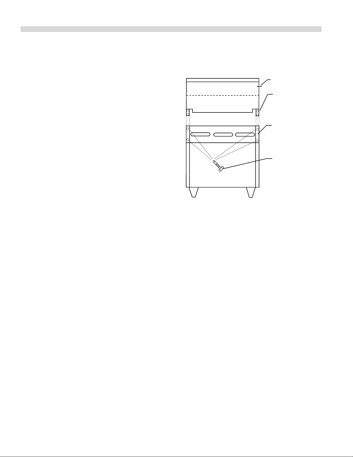
Mounting Instructions for Backguards, Low
Prole Backguards, Single-Deck High Shelves,
Double Deck High Shelves, Salamanders and
Cheesmelters.
A. Rear of range must be easily accessible.
B. Remove the at-head bolt “A” from each side of the
backguard only when the unit will be placed against
another appliance with a backguard, shelf, or broiler.
C. Place the backguard, high shelf, salamander, or
cheesmelter on the rear of the range, slipping the
support brackets into the openings in the burner box
side.
D. Securely fasten the support brackets to the burner box
sides with (4) 1/4-20 x 3/4 slot truss head machine screws,
or (4) #10B x 1/2 Phillips sheet metal screws. (Hardware
package is supplied.)
E. Remove front panel.
F. If the appliance is banked with others that have
backguards installed, replace the at head bolts removed
in Step B so that the upright of the backguard is fastened
to upright of the adjacent backguard.
G. Replace the front panel(s).
Gas Connections
A. The type of gas for which the unit is equipped is stamped
on the rating plate, (refer to Rating Plate Location Table
A). Connect a unit stamped “NAT” only to natural gas, and
a unit stamped “PRO” only to propane.
B. In a new installation, have the gas authorities check
meter size and piping to ensure that the gas supply will
deliver sucient pressure to operate the unit properly.
C. When adding or replacing equipment, have gas
authorities check gas pressure to ensure that the existing
meter and piping will supply fuel to the appliance with
no more than 1/2 inch WC
(0.12 kPa/12.5 mbar) pressure drop during operating.
D. Before turning on the main gas supply, check the unit to
be certain that all the valves are in the “OFF” position.
E. When checking gas pressure, be sure that all other
equipment on the same gas line is turned “ON.” A preset
gas pressure regulator is supplied with GARLAND
Restaurant Series Equipment. It may be necessary to
adjust the regulator to deliver fuel at the pressure shown
on the rating plate.
Part # 4519070 Rev 01 (12/07)Page 12
Page 13

INSTALLATION Continued
BROILER AND FRYER
REPRESENT TYPICAL UNITS
RAIL FLANGE
BACKGUARD
CONNECTING BRACKETS
REAR OUTER FLANGE
CHANNEL BRACKETS
SWING IN FOR
SHIPPING
F. The appliance and its individual shut-o (supplied by
others) must be disconnected from the gas supply piping
system during any pressure testing of that system at
pressures in excess of 1/2 PSIG
(3.45 kPa/34.5 mbar). The appliance must be isolated
from the gas supply piping by closing its individual
manual shut-o (supplied by others) during any pressure
testing of the gas supply piping system at test pressures
equal to or less than
1/2 PSIG (3.45 kPa/34.5 mbar).
Testing and Adjustments
All ttings and pipe connections must be tested for
leaks. Use approved gas leak detectors, soap solution or
equivalent, checking over and around all the ttings and
pipe connections. DO NOT USE A FLAME! Accessibility to
all gas lines and ttings require that valve panel(s) lower
front panel(s), and/or oven rack(s) be removed. It may be
necessary to remove, or at least raise and securely prop
griddle(s), hot top(s), and /or top grate(s). All parts removed,
(including fasteners), should be stored safely for reinstallation.
1. Be sure that all valves and thermostats are in the “OFF”
position.
2. Turn on the main gas supply valve. Light all pilots.
For ease of attaching the supply line, there is a removable
cover on the terminal box.
Permanent connection to the electrical service must comply
with local codes, or in the absence of local codes, with the
national electrical code.
A wiring diagram is attached to the rear of each appliance
Installation of a Common
Front Rail & Backguard
1. All units must be properly aligned and leveled.
2. Remove the control panels on fryers and preparation
tops. Loosen the main top to allow the rail ange to t
between the main top and the frame.
3. The rail ange must be tucked under all the main tops
and fastened to the framework.
4. The front rail is anchored at the front using spacers and
screws provided.
5. Install connecting brackets between each pair of units to
receive backguard and pull the units together.
6. Install bayonet backguard by sliding it down over the rear
outer anges.
3. Leak test all valves and ttings as described above.
Correct any leaks as required and recheck.
4. Shut o all valves and set thermostat dials to “OFF” or
lowest position.
All units are tested and adjusted at the factory, however,
burners and pilots should be checked upon installation and
adjusted if necessary.
Electrical Connection
IMPORTANT – This appliance must be electrically grounded
in accordance with local codes, or, in the absence of local
codes, with the national Electrical code.
When the appliance is ordered and equipped for 220/240
volt operation, the supply line must be connected to the
wiring terminations located inside the terminal box at the
rear of the appliance.
NOTE: Open burner top grates and preparation tops have
rear return ange which is placed inside the rear backguard.
Part # 4519070 Rev 01 (12/07) Page 13
Page 14

INSTALLATION Continued
Assembly of Broiler
Steel Grate Rods
Each broiler is supplied with (14) 15-inch/381mm, (-18B),
21-inch/533mm, (-24B), 26 inch/660mm, (-30B), or 31-inch/
787mm, (-36B) long steel rods. These rods are to be installed
in the grooves on the support brackets, which are atop the
burners.
Briquettes
For best cooking results, it is recommended that the correct
amount of briquettes are installed in the broiler. Refer to
the table and drawing below for the proper arrangement
of briquettes. When all the briquettes have been placed as
instructed, install the top grate sections.
MODEL -18B -25B -30B -36B
Rows front to rear 7 7 7 7
Rows left to right 7 11 14 17
Sanitary Countertop Seal
When the broiler is installed on a countertop, the National
Sanitation Foundation, (NSF), International recommends
that it be sealed in accordance with NSF standards per the
following instructions:
1. Unit should be located on a non-combustible, level
countertop surface.
2. Thoroughly clean the bottom perimeter of the broiler and
the countertop around the bottom of the broiler.
3. Apply a generous bead of silicone sealant around the
entire outside perimeter of the broiler bottom.
4. The broiler can be secured to the countertop by inserting
the 3/8-inch (9.5mm) diameter crating bolts through
the counter from the bottom, (via predrilled 1/2-inch
(12.7mm) diameter holes), and threading them into the
nut inserts in the bottom of the nit.
5. Smooth the silicone sealant with a nger or tool to
provide a cover seal.
Assembly of Optional Stands
Space briquettes evenly on rods in number of rows and
columns specied for your particular model.
1. Fit stand ends together.
2. Secure stand together with (8) 10-24 machine screws,
lock washers and 10-24 hex nuts, (provided). Use only the
front and back pieces.
3. If the stand exceeds a four, (4), foot length, use the
optional cross member. Optional cross member
mounting brackets are secured with ten, (10) each of the
following, (provided): 10-24 machine screws, 1/4-inch
lock washers, and 10-24 hex nuts.
4. Position a square foot insert in the bottom of one of the
legs, and use a light hammer to tap the insert upward
into the leg until it seats at the collar ange.
5. Repeat step 4 for each.
Part # 4519070 Rev 01 (12/07)Page 14
Page 15

OPERATING INSTRUCTIONS
Starre Sentry Ranges
General Notes
NOTE: Models with sux “E” are equipped with an electric
spark ignition module for pilot burner ignition.
WARNING: If the pilot is extinguished either intentionally
or accidentally, no attempt should be made to relight for at
least ve, (5) minutes.
Open Type Hot Plate
All burners are equally rated, and may be used for either
fast boiling or simmering. The pan supports will safely
accommodate pans from 5 inches, (125mm), in diameter. It
is, however recommended that pans larger than 12 inches,
(300mm), be placed only on the rear burners.
NOTE: For maximum eciency and stability, use at bottom
utensils and center them over the burner head.
Lighting
(Models equipped with ame supervision devices):
1. Push in the valve knob, and turn it counter clockwise to
the ignition position.
2. While holding the valve knob fully in, light the pilot
burner with a match.
NOTE: On ranges equipped with electric spark ignitors, press
the ignitor button and observe that the pilot lights. If it does
not, repeatedly depress the ignitor button until it does.
3. When the pilot is lit continue to hold the valve knob fully
in for at least 30 seconds, then release it. If the pilot goes
out, wait for ve (5), minutes, then repeat from step 1.
3. When all pilots are lit, push the burner valve knob in
and turn counter-clockwise to the desired ame height
setting.
4. To turn the burner o, turn the dial to the circular “OFF”
symbol.
5. To turn o all pilots, turn the pilot dial to the circular “OFF”
symbol.
CAUTION: Gas will ow to the top burners even if the pilots
are not lit. Gas will not be interrupted. It is the responsibility
of the installer to check the ignition of all burners and ensure
that it is proper. SHOULD IGNITION FAIL AFTER 10 SECONDS,
TURN THE BURNER VALVE OFF, WAIT 5 MINUTES AND TRY
AGAIN.
Solid Hot Tops
NOTE: All burners are controlled by a ame supervision
device.
Use of the solid hot tops is recommended where long-term
stock pot cooking is required for soups, sauces or stock. Pots
can be placed anywhere on the hot top.
Recommended preheat time is 30 minutes. This will ensure
that the casting is thoroughly saturated with heat. Pots
should have at bottoms for maximum surface contact.
Warped or dented pots will not transfer heat evenly, wasting
energy and resulting in uneven cooking patterns. During
slow periods, it is advisable to lower the burner setting to
conserve energy.
Lighting
1. Push in the valve knob, and turn it counter-clockwise to
the ignition position.
4. When the pilot has been established, push the valve knob
in again and turn it counter-clockwise to the desired
ame setting position, lighting the burner.
5. To turn the burner o, turn the dial to the circular “OFF”
symbol. The safety device will disengage within 60
seconds.
(Models not equipped with ame supervision devices):
1. Push in the pilot valve knob and turn it counter clockwise
to the ignition position, (see caution below).
2. Light all pilots with a match.
Part # 4519070 Rev 01 (12/07) Page 15
2. While holding the valve knob fully in, press the ignitor
button and observe that the pilot lights. If it does not,
repeatedly depress the ignitor button until it does.
3. When the pilot is lit, continue to hold the valve knob fully
in for at least 30 seconds, then release it. If the pilot goes
out, wait for ve, (5), minutes, then repeat from step 1.
4. When the pilot has been established, push the valve knob
in again and turn it counter-clockwise to the desired
ame setting position, lighting the burner.
5. For low ame or simmer push in the valve knob and turn
it counter-clockwise to the low ame position.
Page 16

OPERATING INSTRUCTIONS Continued
6. To turn the burner o, turn the dial to the circular “OFF”
symbol. The safety device will disengage within 60
seconds.
Griddles
NOTE: All burners are controlled by a ame supervision
device.
Griddle tops are designed to have food cooked directly on
the surface. Do not put pots or pans on the griddle surface.
This will scratch or nick the surface and result in poor
cooking performance and sticking of product.
Check the grease container and empty frequently during
heavy use to prevent overow.
Lighting
Refer to the section titled “SOLID HOT TOPS’ on the previous
page for detailed instructions.
Oven (Standard)
Lighting
1. Push in the valve knob, and turn it counter-clockwise to
the ignition position.
During the cooking process in a conventional oven, a vapor
barrier and a layer of “cool” air covers the exposed area of
the product. In a forced air oven, the fan pushes the heated
air over and around the product, sweeping away the vapor
barrier and cool air, permitting faster heat penetration. This
action permits the use of lower temperatures and shorter
cooking times.
The rule of thumb for determining the cooking temperature
is to reduce the set temperature by approximately 80°F,
(28°C), from that which you would use in a conventional
oven, and that the product be checked at a point midway in
the time required in a conventional oven.
Lighting
Refer to the section titled ‘STANDARD OVEN’ on the previous
page for detailed instructions.
Start Up
1. Set the power switch to the” COOK” position.
2. Turn the oven valve knob to the “ame” symbol.
3. Turn the thermostat to the desired setting.
Cool down
2. While holding the valve knob fully in, press the ignitor
button and observe that the pilot lights. If it does not,
repeatedly depress the ignitor button until it does.
3. When the pilot is lit, continue to hold the valve knob fully
in for at least 30 seconds, then release it. If the pilot goes
out, wait for ve (5), minutes, then repeat from step 1.
4. When the pilot has been established, push the valve
knob in again and turn it counter-clockwise to the oven
ame position, then set the thermostat to the desired
temperature.
5. To turn the burner o, turn the dial to the circular “OFF”
symbol. The safety device will disengage within 60
seconds.
“RC” Convection Ovens
The forced air range oven consists of a food preparation
chamber completely sealed from the combustion area.
This eliminates the possibility of contamination from ue
products and permits an ecient method of circulating the
heated air within the cooking chamber.
1. Turn the oven valve knob to the circular “OFF” symbol.
2. Turn the thermostat to its lower setting.
3. Open the oven door.
4. Set the power switch to the “COOL DOWN” position.
Shut Down
1. Turn the oven valve knob to the circular “OFF” symbol.
2. Turn the thermostat to its lowest setting.
3. Set the power switch to the “OFF” position.
Operating Suggestions
The motor on your range convection oven is maintenance
free since it is constructed with self-lubricating sealed ball
bearings. It is designed to proved durable service when
treated with ordinary care. We have a few suggestions to
follow on the car of your motor.
Part # 4519070 Rev 01 (12/07)Page 16
Page 17

OPERATING INSTRUCTIONS Continued
A. When the motor is operating, it cools itself internally by
air entering the rear of the motor case, provided proper
clearance has been allowed.
B. Since the blower wheel is in the oven cavity it is at the
same temperature as the oven. If the motor is stopped
while the oven is hot, the heat from the blower wheel is
conducted down the shaft and into the armature of the
motor. This action could shorten motor life.
C. We recommend, at the end of the bake or roasting
period, when the oven will be idle for any period of time
or before shutting down completely, that the doors
be left open, and by use of the cool-down position on
the fan switch, the fan continues to run for at least 20
minutes. The “FAN” should never be turned “OFF” when
the oven is “HOT”.
Fryers and Broilers
Range-Match Broilers
To ensure long life and service, it is imperative that the
cooking surface be carefully broken in or “seasoned” in the
follow manner:
Lighting Instructions
Model (H,S) 280 – (18,24,30,36)B
1. One pilot serves two burners and is located between
those burners.
2. Push red spark buttons several times to ignite pilot
burners.
3. Ensure pilots are lit by viewing through pilot view hole on
front of unit.
Model ST280 – (18,24,30,36)B
1. Push in the valve knob and turn counter-clockwise to the
ignition position.
2. While holding the knob fully in, depress the ignitor
button and visually conrm that the pilot lights. If the
pilot does not light, repeatedly press the ignitor button
until ignition is achieved.
3. After the pilot is lit, continue to hold the valve knob in for
at least 20 seconds, then release it. If the pilot goes out,
wait ve, (5), minutes, then repeat the procedure.
1. Remove all factory applied protective material by
washing with hot water and a mild detergent or soap
solution. Rinse and dry thoroughly.
2. Apply a light coat of cooking oil to the cooking surface.
Wipe away the excess.
3. Turn all the valves to a low setting and allow the grids to
heat slowly for 30 minutes. Allow the oil to remain on the
cooking surface for an additional 3 to 4 minutes, then
wipe o.
4. Reset valves to your desired operating temperature and
apply a second coat of oil.
Allow the broiler to reach the set temperature, wait an
additional 2 to 3 minutes, then wipe away the excess oil.
The broiler is now ready for use.
NOTE: Unless your products contain a sucient amount of
fat, the grid racks may require re-seasoning before use to
prevent sticking. Grid racks must be re-seasoned after every
cleaning.
4. When the pilot is established, push in the valve knob
again and turn it counter-clockwise to the full ame
position, igniting the main burner.
5. For low ame or simmer, push in the valve knob and turn
it to the low ame position.
6. To turn the burner o, push in and turn the valve knob to
the circular “OFF” symbol.
Shut down
1. Turn all gas valves o.
2. If the unit is to be shut down for an extended period of
time, turn the in-line service valve to the “OFF” position,
(this valve is not factory supplied).
Part # 4519070 Rev 01 (12/07) Page 17
Page 18

OPERATING INSTRUCTIONS Continued
Range-Match Fryers
Before Operating the Fryer
1. Before leaving the factory, the fryer was tested, and the
thermostat calibrated with oil in the fry tank; therefore it
is necessary to clean the fry tank before lling with frying
compound. Use detergent or other cleaning agents with
hot water. Thoroughly rinse and dry.
2. Never operate the pilot or burner with an empty fry tank.
It will only take a few minutes to ruin the tank and void
the warranty.
3. If the fryer is equipped with a cold-rolled steel fry tank,
and is not to be lled immediately after cleaning, coat
the entire tank surface with shortening or cooking oil to
prevent rusting.
Fryer Burner
The burner used in Starre Range-Match Series Fryers
is a patented design which requires no primary air; so
adjustment of primary air is not possible. When the proper
gas is supplied at the proper pressure, and the ceramic
targets are properly adjusted, combustion will begin about
even with the bottom of the ceramics. The characteristic
sound is a low roar, similar to a blow-torch.
NEVER throttle down the incoming gas in an eort to make
the ame burn directly on the orice.
Lighting Instructions
1. Before lighting the pilot, ll the fry tank with frying
compound.
2. Turn the thermostat to the “OFF” position. Depress and
turn the gas control knob to the “OFF” position. Wait ve
(5) minutes.
3. Turn the control knob to the “PILOT” position.
4. Push the control knob in and press the piezo ignitor.
Continue to hold the control knob in for about 60
seconds after the pilot is lit.
5. If liquid frying compound is used., Turn the gas control
knob to the “ON” position, and set the thermostat to the
desired temperature.
6. If a hydrogenated, (solid), frying compound is used,
pack the fry tank with the compound and turn the gas
control knob to the “ON” position for approximately ve,
(5) seconds, then turn it “OFF” for approximately ten,
(10), seconds. Repeat turning the control knob “ON,” then
“OFF” until the frying compound is melted. If smoking
occurs during this process, the heat is being applied too
fast, scorching the frying compound. If the process is
continued in this way, permanent damage to the fry tank
may occur.
7. If the pilot goes out during this process, repeat the
procedure from step 2.
Shut down
For complete shut down, turn both the thermostat and the
gas control knob to the “OFF” position.
Part # 4519070 Rev 01 (12/07)Page 18
Page 19

PRODUCT APPLICATION INFORMATION
General
The range is the workhorse of the kitchen because of its
versatility. Most frequently used in small applications, such as
cafes, schools, church kitchens, rehouses, and small nursing
homes where demands are less taxing. As a general rule of
thumb, one four to six burner range with a hot top will be
adequate for a restaurant seating 30 to 35.
The top of the range is designed for exibility and the
preparation of numerous dierent types of products. It may
be equipped with two, or even three dierent types of tops
and burners, depending on the menu needs. An operation
that cooks to order, or uses the range primarily as back-up
will nd that open burners will suit most of their needs.
Preparation of soups, stocks, or sauces is done on a hot top
where slow, even cooking is desirable.
Heating larger quantities of food can be done more
eciently than heating small quantities. Pots and pans
should be covered whenever possible to reduce energy
consumption.
High acid sauces, such as tomato should be cooked in
stainless steel rather than aluminum to avoid chemical
reaction. Light colored sauces such as Alfredo may be
discolored by the use of aluminum, especially if stirred with
a metal spoon or whip. Saltwater shellsh may pit aluminum
pots if they are frequently used for this purpose
Open Burners
The most traditional uses of open burners are sautéing, pan
frying, and small stock pot work. Short-term cooking is the
most ecient use for the open burner. Pans should cover
as much of the grate as possible to minimize heat loss. The
maximum stock pot size to be used on an open burner is 11
inches, (279mm), diameter. Open burners should be turned
o when not in use to conserve energy. Leaving a ame
burning is of no advantage since the heat is instantaneous.
Hot Tops
Hot tops are recommended where long-term stock pot
cooking is required for soups, sauces or stocks. Pots can be
placed anywhere on the hot top, rather than in one specic
position, as on an open burner. The maximum stock pot size
to be used on the hot top is 12 inches, (305mm), in diameter.
Recommended preheat time for a 12-inch, (305mm), hot top
section is 30 minutes. This will thoroughly saturate the metal
with heat. Hot tops are evenly heated, and have a smooth
surface so that pots may be moved easily to any position.
Pots must have a at bottom for maximum contact with
the hot top surface. Warped or dented pots will not transfer
heat evenly or eciently, wasting energy and resulting in
uneven cooking patterns. Roasting pans with straps should
not be used on a hot top because only the straps will touch
the heated surface and transfer will be minimal. During slow
times, group pots on one hot top section and turn o the
other section(s). This will conserve energy. If needed, the
other section(s). Will preheat in 10 to 15 minutes due to the
retained heat in the metal.
Griddle Tops
Griddle tops are designed to have food cooked directly on
the surface, for example hamburgers, eggs, pancakes, has
browns, etc. Do not put pots or pans on the griddle surface.
This will scratch or nick the surface, resulting in sticking and
scorching of product. Never salt food on a griddle because
this will cause a gummy residue to build up, making the
griddle more dicult to clean. Avoid hitting the griddle plate
with a spatula, as this will also nick the surface. The most
frequently used temperature range for griddles is 325° to
350°F, (163° to 177°C). Check and drain the grease drawer
frequently during heavy use to prevent overowing. Over
a period of time, some discoloration of the steel griddle
plate will occur. This will not aect performance. For best
cooking results, keep the griddle surface as clean and shiny
as possible.
Oven (Standard)
The temperature is automatically controlled by the
thermostat, so satisfactory results can be obtained with
condence again and again.
For best performance, these instructions should be followed:
A. Grid Shelves There are two shelf positions. The correct
shelf position should be decided by the size of the
product to be cooked. When the best position has been
determined, push the shelf fully into the oven until
contact with the back wall stops its movement.
Part # 4519070 Rev 01 (12/07) Page 19
Page 20

PRODUCT APPLICATION INFORMATION Continued
B. Tray Size One cake tray up to 24 x 22 inches,
(610 x 560mm), can be placed on each shelf. Single trays
or dishes should be centered on the shelf. Trays must not
be allowed to overhand the shelf on any side, since this
will inhibit proper heat circulation.
C. Preheat time Allow at least 45 minutes after turning on
the cold oven, with the thermostat set at the desired
temperature before loading with food. Load product
quickly and immediately close the door.
D. Thermostat The thermostat automatically controls the
heat to maintain the selected temperature.
Range Base Convection Oven
Generally, a temperature 25° to 50°F (-4° to 10°C), lower than
that specied in recipes for standard ovens should be used.
Cooking time may be reduced, depending on the product.
A 2% to 5% reduction in cook time is a general rule. Keep a
close check on any product being prepared for the rst time.
The size of the load, temperature of the product going in,
and moisture content are the major factors that inuence
necessary cook times and temperatures. Successfully
prepared products should be recorded with their times and
temperatures for future reference.
Preheat the oven thoroughly before loading. It will take
approximately 15 minutes for the oven to reach 350ºF, 177ºC.
Best results will be attained when the oven is allowed to
preheat for 30 minutes or more for thorough heat saturation.
Center the load on the oven racks to allow for proper heat
circulation around the sides. The oven will hold three, (3),
18” x 26”, (457mm x 660mm), sheet pans, six, (6), 12” x 20” x
2.5”, (305mm x 508mm x 64mm), steam table pans, or one,
(1) 17.75” x 25.75”, (451mm x 654mm), roast pan. Never place
pans directly on the oven bottom. Always use the lowest rack
position that will allow the heated air to circulate within the
oven cavity. Load and unload food as quickly as possible to
prevent excessive temperature drop. For even baking, avoid
using warped pans.
Do not use a deep pan for shallow cakes, cookies, etc., as heat
circulation across the top of these items is essential for even
browning. To prevent excessive shrinkage, roast meats at a low
temperature; 250°F, (121° to 163° C), When rethermalizing frozen
products, preheat the oven 50°F, (10°C), higher than the cooking
temperature to compensate for heat loss during and after
loading. Return the thermostat to the cooking temperature after
loading.
To conserve energy, turn the oven o when not in use. If you
cover pans with aluminum foil, be sure to crimp it tightly
around the edges to prevent the foil from blowing o in the
oven. Any food or other matter which becomes lodged in the
fan must be removed as soon as the oven is cool.
Part # 4519070 Rev 01 (12/07)Page 20
Page 21
ADJUSTMENTS
Minimum Flame
Adjuster
The top and oven orices are xed and cannot be adjusted.
Proper rate will be attained if the gas supply pressure is
correct. Pressure may be checked by using the 1/8” NPT
manifold pressure tap. A properly adjusted air shutter will
provide for a distinct blue ame over the entire port area of
the burner when at full rate.
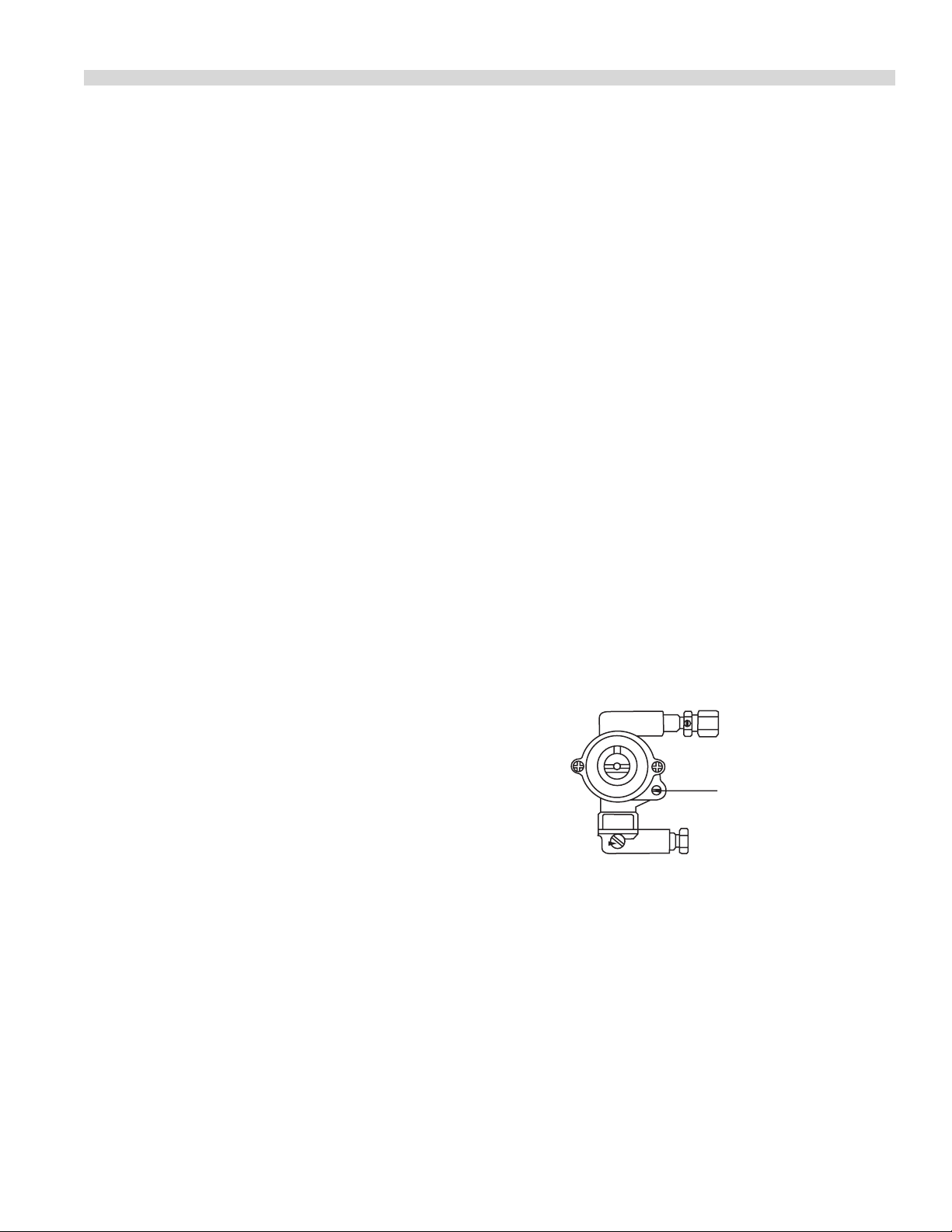
Pilot Burner Adjustment
Set all pilots so that the ame envelopes the tip of the
thermocouple.
Open Burners Safety Device, (ST & STE Series)
Pilot Adjustment is made by turning the screw on the
adjusting valve located at the pilot outlet of the valve body
clockwise to decrease, or counter-clockwise to increase.
Open burners without Flame
Safety Device, (S.Series)
Pilot adjustment is made at the adjusting valve located at the
pilot block(s) underneath the top grate by turning the screw
clockwise to decrease, or counter-clockwise to increase.
Griddles and Hot tops
“Minimum” Flame Setting
Griddle
Minimum ame setting is adjusted at the screw located on
the valve body, by turning the valve to the “MIN” position,
and turning the screw clockwise to decrease the ame size,
or counter-clockwise to increase the ame size. Set to the
lowest stable blue ame along the entire burner length.
Range Match Broiler
(280 Series & S280 Series)
Broilers are equipped with “HI/LO” valves which fracture an
adjustable low ame setting. To adjust:
1. Burner must be cold.
2. Pilot ames should be lit and properly adjusted.
3. Turn the dial to the “LOW” or “MIN” position and remove.
4. With a screwdriver, turn the small adjusting screw inside
the valve stem until the burner ame is at the desired
low setting, (minimum 3/16”/5mm ame along the entire
burner).
Pilot adjustment is made at he adjusting screw located on
the valve body by turning the screw clockwise to decrease,
or counter-clockwise to increase.
Oven, (Standard and ‘RC’)
Pilot adjustment is made by turning the screw on the
adjusting valve located at the pilot outlet of the valve body
clockwise to decrease, or counter-clockwise to increase.
Range Match Broilers
1. The pilot adjusting valves are located on the manifold.
2. With the valve panel in place, the pilots can be adjusted
with a long, thin-bladed screwdriver inserted through the
small hole in the valve panel to obtain a 1 5/8”, (41mm),
ame.
5. Replace the dial and return to the “OFF” position.
(ST 280 Series)
1. Set gas tap to low position.
2. Connect a U-gauge manometer to the test nipple located
down-stream of the gas tap.
Part # 4519070 Rev 01 (12/07) Page 21
Page 22

ADJUSTMENTS Continued
4
5
0
5
0
0
5
5
0
1
5
0
3
0
0
2
5
0
3
0
0
3
5
0
4
0
0
Calibration
Lock Screws
By-pass Flame
Adjuster
Indicator Mark
Calibration
Plate
Dial
Stop
MODEL
FDO
3. The manometer should read 1.8” WC for natural gas, or
8”WC for propane.
4. If the reading on the manometer does not agree with
the pressure specied in step 3, adjust by turning the
adjusting screw clockwise to reduce the pressure, or
counter-clockwise to increase.
Burner Gas / Air Adjustment
Variation in eld condition and/ or rough handling of the
equipment in transit may create the need for adjustment to
the primary burner air. Check operation and adjust as below
to provide a sharp blue ame at full rate, (valve open fully, or
thermostat calling for maximum gas ow).
On the burner, locate the air shutter, (at the end where the
burner orice enters). Loosen the locknut so that the air
shutter turns freely. Turn on the gas to the burner. Rotate the
air shutter to obtain the following:
a. Open, (Star), Burner – 1/2”, (13mm, stable, sharp inner
blue cones.
b. Hot tops & Griddles – 5/16”, (8mm) stable, sharp inner
blue cones.
By-Pass Adjustment
The Robertshaw FDO snap/throttle thermostat requires that
the by-pass ame be properly adjusted. To adjust proceed as
follows:
1. Ensure pilot ame is lit and adjusted.
c. Oven Burners – If the ames are soft, unstable, or
show yellow tipping, increase the amount of air by
opening the air shutter.
NOTE: The ame safety valve is a protective device which
allow gas to ow to the burner only when the pilot is burning,
(used on all models except H/P 280 Series)
A too loose or too tight connection of the thermocouple nut
to the automatic pilot valve can prevent the thermocouple
from activating the valve. The nut should be drawn up nger
tight, then tightened an additional 1/4-turn ONLY with a
wrench.
It is recommended that an automatic pilot test kit be used
to check the thermocouple and hood assembly of the safety
valve. A visual examination of the thermocouple lead should
be made to conrm that there are no cracks.
FDO Heavy Duty Oven control
The model FDO oven thermostat is a precision-made
instrument, carefully set at the factory to accurately control
oven temperatures from 150° to 500°F,
(66° to 260°C). All adjustments are accessible from the front
of the appliance after moving the dial. To remove the dial,
grasp the outer edges and pull straight out.
2. Turn oven temperature control to 200°F, (93°C), and allow
the oven to heat for three minutes.
3. Turn, the oven temperature control to the lowest
position, then turn slowly counter-clockwise until the
audible “click” is heard.
4. Making sure the oven temperature control dial is not
disturbed, turn the by-pass ame adjusting screw
clockwise to decrease, or counter-clockwise to increase
the ame on the burner to the lowest possible stable
ame. When properly adjusted, the by-pass ames will
cover the entire length of the burner.
Calibration Instructions
Field calibration is seldom necessary and should not
be resorted to unless experience with cooking results
undoubtedly indicate that the control is not maintaining
the temperature for which the dial is set. To check oven
temperatures when calibrating, use only a reliable mercury
thermometer, or preferably an oven pyrometer. To check
calibration, proceed as follows:
Part # 4519070 Rev 01 (12/07)Page 22
Page 23

ADJUSTMENTS Continued
1. Place the thermocouple of the test instrument or reliable
mercury thermometer in the center of the oven.
2. Turn the oven temperature control knob to 400°F, (204°C),
and allow the oven to cycle at least three times.
3. Continue to monitor the oven temperature, recording
the readings at 5 minute intervals until three successive
readings are within 5°F, (2°C), of each other.
If the temperature does not read within 15°F, (8°C), of the dial
setting, recalibrate as follows.
1. Remove the oven temperature control dial, making sure
the setting is not disturbed.
2. Hold the calibration plate, (located directly behind the
control dial), and loosen the two calibration lock screws
until the plate can be rotated independently of the
control.
3. Turn the calibration plate until the temperature indicated
on the plate corresponds with the reading on the test
instrument. Hold the plate in place and tighten the
screws rmly.
4. Repeat step 3 in the previous section, checking the
temperature to ensure the adjustment has been made
properly.
5. Replace the temperature control dial.
NOTE: If adjustment of the calibration plate is prevented by
the position of the lock screws, the screws can be moved to
other holes that have been tapped for them.
Fryer Thermostat
Calibration
Field calibration is seldom necessary and should not
be resorted to unless experience with cooking results
undoubtedly indicate that the control is not maintaining
the temperature for which the dial is set. To check fryer
temperature for calibration, use a pyrometer.
1. Suspend the thermocouple in the center of the fry tank
approximately 3 inches, (756mm), deep.
2. Allow the burner to cycle at least four times.
3. The fourth time the burner cycles OFF, compare your
instrument reading with the thermostat setting.
MAINTENANCE AND CLEANING
Seasoning
Griddle
A. Remove all factory applied protective material by
washing with hot water, mild detergent or soap solution.
B. Apply a thin coat of cooking oil to the griddle surface,
about one ounce per square foot of griddle surface.
Spread over the entire griddle surface with a cloth to
create a thin lm. Wipe o any excess oil with a cloth.
C. Light all burners, set a lowest possible setting. Some
discoloration will occur when heat is applied to steel.
Part # 4519070 Rev 01 (12/07) Page 23
D. Heat the griddle slowly for 15 to 20 minutes. Then wipe
away oil. Repeat the procedure 2 to 3 times until the
griddle has a slick, mirror like nish. Do this until you have
reached the desired cooking temperature.
IMPORTANT: Do not attain high (on valve control or 450° (on
thermostat control) during “break-in” period.
NOTE: Steel griddle surface will tone (blue discoloration)
from heat. This toning will not diminish function or operation
is not a defect.
The griddle will not require reseasoning if it is used properly.
If the griddle is over heated and product begins to stick to
the surface it may be necessary to repeat the seasoning
process again. If the griddle is cleaned with soap and water it
will be necessary to reseason the griddle surface.
Page 24

MAINTENANCE AND CLEANING Continued
Cast Iron top Grates
First, remove the cast iron top grates from the range. Wash
the cast iron top grates thoroughly with a mild soap and
warm water. Dry the cast-iron top grates thoroughly with a
clean cloth. Immediately after drying, season the top grates
lightly with a non-toxic oil, (Liquid vegetable oil or Pam spray
oil) WARNING; DO NOT SEASON THE TOP GRATES WHILE ON
THE RANGE TOP! Seasoning grates on the range top over an
open ame could cause a ash re. After seasoning, replace
the top grates onto the range. Turn all the range top sections
“ON LOW”. Allow the top sections to burn in this manner
for at least 20 minutes before using pots or pans on the top
grates. SEASONING OF THE TOP GRATES WILL BE REQUIRED
WHENEVER THEY HAVE BEEN CLEANED. FAILURE TO SEASON
GRATES WILL CAUSE RUSTING.
Cleaning
Painted Finishes
Establish a regular cleaning schedule. Any spills should be
wiped o immediately.
The oven should be permitted to cool down before cleaning
exterior surfaces.
1. Wipe exposed, cleanable surface when cool with a mild
detergent and hot water. Stubborn residue spots may be
removed with a light weight non metallic scouring pad.
Dry thoroughly with a clean cloth.
Use a paste (of water and a mild scouring powder) if you
have to, but never rub against the grain. All stainless steel has
been polished in one direction. Rub with the polish lines to
preserve the original nish. Then thoroughly rinse as before.
To prevent ngerprints there are several stainless steel
polishes on the market that leave an oily or waxy lm. Do not
use on surfaces that will be in contact with food.
Stainless steel may discolor if overheated. These stains can
usually be removed by vigorous rubbing with a scouring
powder paste. Use only stainless steel, wool or plastic tools if
necessary to scrape o heavy deposits of grease and oil. Do
not use ordinary steel scraper soft knives as particles of the
iron may become imbedded and ruse. STEEL WOOL SHOULD
NEVER BE USED.
Either a typical bleach solution or hot water can be used to
sanitize stainless steel with out harm.
Oven Interior (Porcelain Enamel)
NOTE: Disconnect line cord (if applicable from power supply
before cleaning or servicing.
1. Before cleaning oven interior, remove all oven racks
and guides (if “RC” base). Oven racks and guides can be
cleaned with a mild soap and warm water or run through
dish washer.
2. The porcelain interior can be cleaned with oven cleaners
such as “Easy-O, or “Dow Oven Cleaner”.
2. Stainless steel should be cleaned using a mild detergent,
a soft cloth and hot water.
If necessary to use a nonmetallic scouring pad, always rub in
the direction of the grain in the metal to prevent scratching.
Use a water based stainless cleaner (Drackett Twinkle), if you
want a high shine.
Stainless Steel
For routine cleaning just wash with a hot water and
detergent solution. Wash just a small area at a time or the
water will evaporate leaving the chemicals behind causing
streaking.
Rinse the washed area with a clean sponge dipped in a
sanitizing solution and wipe dry with a soft clean cloth
before it can dry.
Follow product manufacturer’s instructions for proper use.
Griddle
To produce evenly cooked, browned griddle products, keep
griddle free from carbonized grease. Carbonized grease on
the surface hinders the transfer of heat from the griddle
surface to food product. This results in uneven browning
and loss of cooking eciency, and worst of all, carbonized
grease tends to cling to grilled foods, giving them a highly
unsatisfactory and unappetizing appearance. To keep the
griddle clean and operating at peak performance, follow
these simple instructions:
A. AFTER EACH USE clean griddle thoroughly with a grill
scraper or spatula. Wipe o any excess debris left from
cooking process.
B. ONCE A DAY clean griddle surface with a grill brick and
grill pad. Remove grease container and clean thoroughly,
in same manner as any ordinary cooking utensil.
Part # 4519070 Rev 01 (12/07)Page 24
Page 25

MAINTENANCE AND CLEANING Continued
C. ONCE A WEEK clean griddle surface thoroughly. If
necessary, use a grill stone or grill pad over the griddle
surface. Rub with grain of the metal while still warm.
A detergent may be used on the plate surface to help
clean it, but care must be taken to be sure it is thoroughly
removed. After removal of detergent, the surface of the
plate should be covered with a thin lm of oil to prevent
rusting. To remove discolorations, use a non-abrasive
cleaner. Before
re-using, the griddle must be reseasoned. Keep griddle
drain tube to grease container clear at all times on those
models without grease container.
CAUTION This griddle plate is steel, but the surface is
relatively soft and can be scored or dented by careless use of
spatula.
Be careful not to dent, scratch, or gouge the plate surface.
This will cause food to stick in those areas. Also, note, since
this is a steel griddle if a light coating of oil is not always
present rust will develop on exposed and uncoated areas.
Open Top Burners
Cleaning of the range top burner is a simple procedure and,
if done at regular intervals will prolong the life of the range
and ensure good ame characteristics.
The most common problem with open burner ranges is
spillage. Once the burner ports are partially plugged with
food, the air-to-gas mixture is disturbed and results in an
inecient burner.
Wipe any spills as they occur.
Grids and trays should be removed daily, washed, rinsed and
dried thoroughly.
Use a wire brush to clean the ports of the burners. Ignite and
check for clogged holes.
Reinstall and check the ame pattern. Readjust the air
shutter if necessary.
If a yellow ame appears around the edges instead of being
uniformly blue, it is usually a sign of grease and dirt in the
throat of the burner. Remove and clean the burner and
readjust the air shutter.
Cast Iron Top and Ring Grates
Cast iron top and ring grate(s) can be cleaned with mild soap
and warm water. For baked on material, a wire brush can
be used. Dry thoroughly. Lightly coat with vegetable oil to
help prevent rust from forming. At the rear of the cast iron
top grate there are spills shields. These should be removed
and cleaned. Replace after cleaning to prevent grease and
spillovers dripping down the back of range.
Porcelain Top and Ring Grates
Porcelain top and ring grate(s) should be removed from
the range before cleaning. Clean with warm water, dish
detergent with degreaser and a soft cloth. DO NOT USE
ABRASIVES which will damage the porcelain surface. For
baked on material use of a ber pad or plastic scrubber
and standard oven cleaner is acceptable. Follow the
manufacturers directions for “cold Oven” cleaning method.
Porcelain tops and ring grates can also be processed through
a commercial dish water. Dry thoroughly and handle with
care.
Hot tops
While the surface is still slightly warm, wipe down with a
clean burlap cloth. Burnt on spillage should be scraped o. If
necessary, remove the plate and wash in a sink with soap and
hot water. Dry thoroughly. In damp climates, wipe down with
a light coating of oil to prevent rusting. Avoid excessive use
of water at this could damage the surface and the controls
below.
If any clogged holes are apparent, the burner should be
lifted out and brushed inside and out with a small venture
brush. Each port on the burner itself should be cleaned with
a properly sized wire or thumb drill. Wash with soap and hot
water if grease is observed on the burners. Dry thoroughly.
Part # 4519070 Rev 01 (12/07) Page 25
NOTE: Steel griddle and hot top surface will “tone” (blue/
brown discoloration) from heat. This toning will not diminish
function or operation and is not a defect.
Page 26

CONVERSION INSTRUCTIONS
Servicing must be carried out by a competent person in
accordance with the law.
WARNING: Turn o the gas supply to the appliance at the
service cock before commencing any servicing work.
IMPORTANT: Test for gas soundness on completion of any
servicing work.
The following instructions are intended to describe the
operations necessary to convert equipment from operation
on one gas family to that of another.
1. Ensure that all of the parts necessary to make the
conversion have been supplied as follows:
a. Injector ttings (One required for each main burner)
b. Pilot injector ttings (One required per pilot burner)
c. Gas adjustment label (One required per unit)
If any of the required parts are missing, contact your Garland
dealer before attempting to carry out the conversion.
NOTE: Conversion kits supplied for G31 gas will contain
redundant ttings and markings covering both 37 mbar & 50
mbar gas supplies.
NOTE: Before doing so, refer to Table F (Table H for
Australian Models) in this manual to ensure that the
correct injector has been supplied for the gas supply being
converted to.
4. Replace each pilot injector tting with the new tting
supplied.
NOTE: There are two sizes of pilot injectors identied as
follows:
a. # 32 (2nd family gases) Natural Gas
b. # 23 (3rd family gases) Propane
Ensure that you have the correct pilot injector before
replacing.
Upon completion of all the above operations, follow the
section in the manual on “Commissioning” and ensure
that the setting pressure and all burner ame settings are
adjusted accordingly.
Continuous product improvement is a Garland policy,
therefore specications and design are subject to change
without notice.
2. Remove the burners following the instructions given in
this manual.
3. Replace each injector tting with the new tting that is
supplied.
Part # 4519070 Rev 01 (12/07)Page 26
Page 27

TROUBLESHOOTING
Open Burner – Models not Equipped with Flame Supervision Device
Problem Possible Cause Solution
Burner ame too large Incorrect gas pressure Check gas pressure
Burner ame soft – yellow tip Insucient primary air Adjust air shutter
Flame lifts o burner ports Excessive primary air
Flame burns back to orice
Burner “pops” after shutting o
Delayed ignition Pilot ame too small Adjust pilot ame
Burner ports blocked Clean burner
Incorrect gas/air mixture Adjust air shutter
Incorrect gas pressure Check gas pressure
Pilot burner will not ignite Pilot tap turned o Turn pilot tap on
Pilot orice blocked Clean pilot orice
Pilot tap blocked Clean pilot tap plug
Open Burner – Models Equipped with Flame Supervision Device
Problem Possible Cause Solution
Burner ame too large Incorrect gas pressure Check gas pressure
Burner ame soft – yellow tip Insucient primary air Adjust air shutter
Flame lifts o burner ports Excessive Primary air
Flame burns back to orice
Burner “pops” after shutting o
Delayed ignition Pilot ame too small Adjust pilot ame
Burner ports blocked Clean burner
Incorrect gas/air mixture Adjust air shutter
Incorrect gas pressure Check gas pressure
Pilot burner will not ignite Pilot orice blocked Clean pilot orice
Pilot adjusting screw closed Open and adjust pilot
Pilot repeatedly goes out Pilot ame too small Adjust pilot ame
Loose thermocouple connection Tighten connection
Faulty Thermocouple Replace thermocouple
Faulty ame safety device Replace ame safety device
Low millivolt output on open circuit test Pilot ame too small Adjust pilot ame
Defective thermocouple Replace thermocouple
Millivolt output high in open circuit test,
but low in closed circuit test
Millivolt output high in closed circuit test,
but safety valve will not stay open
No spark to pilots,
(*-E models only)
Faulty ame safety device Replace ame safety valve
Faulty ame safety device Replace ame safety valve
*No power to range Check power supply
*Defective momentary switch Replace switch
*Defective spark module Replace spark module
*Disconnected or loose
High tension wires
Reconnect high tension wires
Part # 4519070 Rev 01 (12/07) Page 27
Page 28
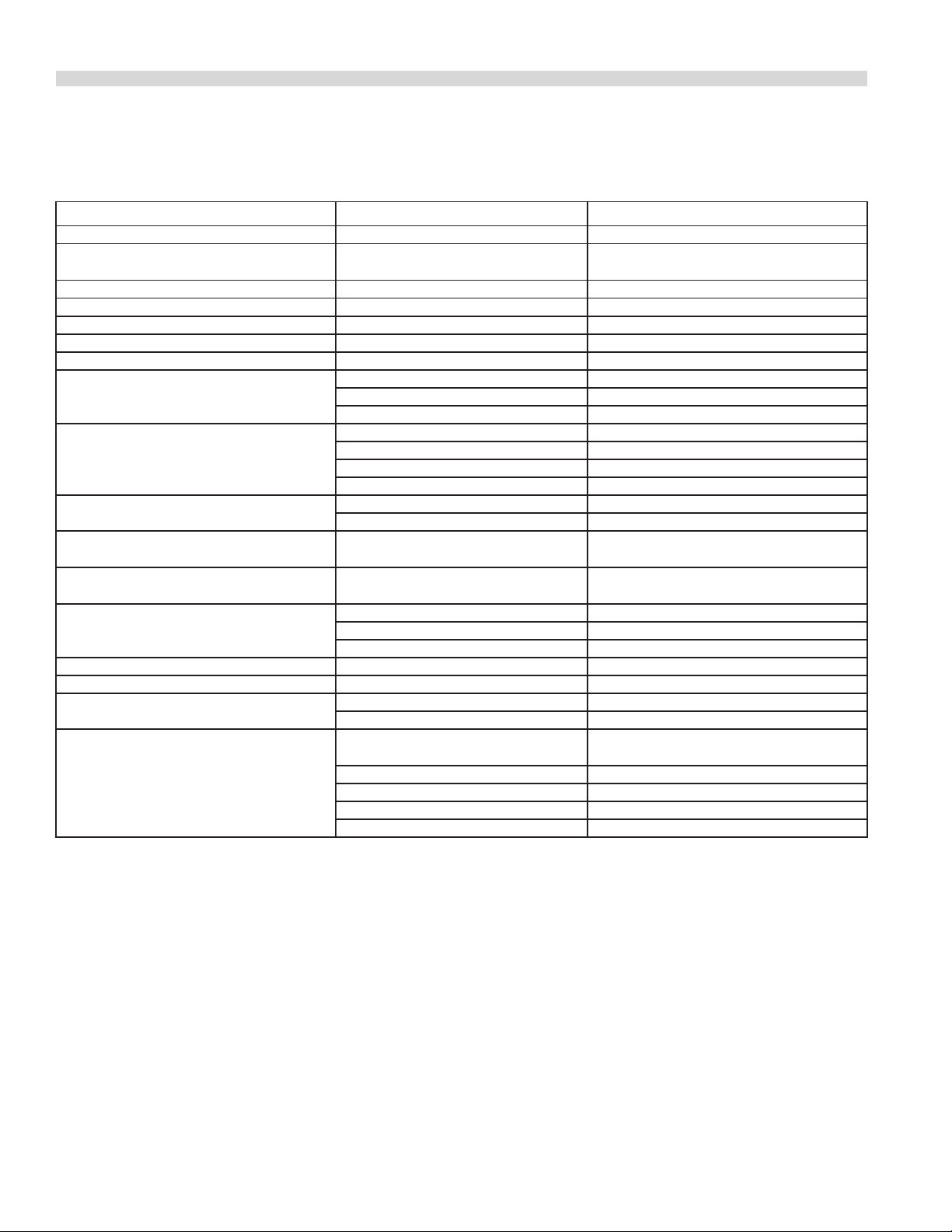
TROUBLESHOOTING Continued
Oven (Standard & Convection)
Problem Possible Cause Solution
Oven too hot or not hot enough Thermostat out of calibration Check calibration
Burner ame shuts o when oven is at
the required temperature.
Burner ame soft-lazy yellow tip Insucient primary air Check aeration shutter setting
Flame lifts o burner ports Excessive primary air Check aeration shutter setting
Burner lifts back to the injector Excessive primary air Check aeration shutter setting
Burner “pops” when turned o Excessive primary air Check aeration shutter setting
Burner ame too large Incorrect setting pressure or injector Check setting pressure or injector
Delayed ignition. Delayed ignition Pilot ame too small Clean burner
Oven pilot keeps going out Faulty thermocouple Check millivolt output
Low millivolt output on open circuit Pilot ame too small Adjust pilot ame length
Millivolt output high in open circuit test
and low in closed circuit test
Test but ame safety valve will not stay
open
Door will not stay closed Insucient tension on springs Adjust tension
Door will not stay open Too much tension on springs Adjust tension
Door not closing on one side Door warped Replace door
Door not level or low in center Trunnion support loose Level and tighten
No spark to pilots (*-”E” Models Only) Disconnected or loose hi-tension
Thermostat has incorrect
by pass rate.
Burner ignition ports blocked Check aeration shutter setting
Incorrect aeration Check millivolt output
Faulty ame safety device Replace ame Safety device
Pilot ame too small Check pilot ame length
Thermocouple connection is loose. Check connection
Defective thermocouple Replace
Faulty ame safety device Replace
Faulty ame safety device Replace ame safety device
Broken spring Replace
Broken hinge link Replace
Trunnion support worn Replace
wires
Defective piezzo Replace piezzo
*No Power to range *Check power supply
*Defective momentary switch *Replace switch
*Defective spark module *Replace module
Replace thermostat
Reconnect hi-tension wires
Part # 4519070 Rev 01 (12/07)Page 28
Page 29
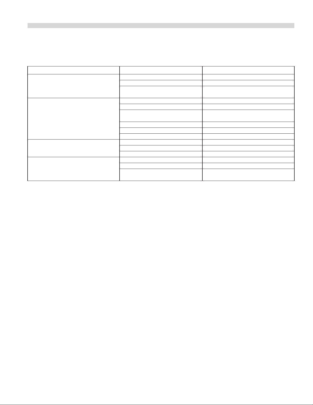
TROUBLESHOOTING Continued
Convection Ovens Only
Problem Possible Cause Solution
Cook/Cool Down switch set to “Cook”
position. Light o. Motor not working
Cook/Cool down switch set to “Cook”
position. Light on. Motor not working
Noisy motor Blower wheel rubbing on oven bae Adjust blower wheel
Cook/Cool down switch set to “Cool
Down” position. Light on. Motor not
working
No power to oven Check power supply
Defective Cook/Cool Down switch Replace switch
Faulty wiring Check condition of wires and all
connections
Defective Cook/Cool Down Switch Replace switch
Defective door switch Replace switch
Faulty wiring Check conditions of wires and all
connections
Defective motor Replace motor
Oven door open Close door
Door switch out of alignment. Align door switch
Blower wheel loose on motor shaft Retighten blower wheel
Defective motor Replace motor
Defective Cook/Cool Down switch Replace cook/Cool Down switch
Defective door switch Replace door switch
Faulty wiring Check conditions of wires and all
connections.
Part # 4519070 Rev 01 (12/07) Page 29
Page 30

TROUBLESHOOTING Continued
Hot Top / Griddle / Broiler
Problem Possible Cause Solution
Burner ame too large Incorrect gas pressure Check gas pressure
Burner ame soft – yellow tip Insucient primary air Adjust air shutter
Flame lifts o burner ports Excessive primary air
Flame burns back to orice
Burner “pops” after shutting o
Delayed ignition Pilot ame too small Adjust pilot ame
Burner ports blocked Clean burner
Incorrect gas / air mixture Adjust air shutter
Incorrect gas pressure Check gas pressure
Pilot burner will not ignite Pilot orice blocked Clean pilot orice
Pilot adjusting screw closed Open adjust pilot
Pilot repeatedly goes out Pilot ame too small Adjust pilot ame
Loose thermocouple connection Tighten connection
Faulty Thermocouple Replace thermocouple
Faulty ame safety device Replace ame safety device
Low millivolt output on open circuit test Pilot ame too small Adjust pilot ame
Defective thermocouple Replace thermocouple
Millivolt output high in open circuit test,
but low in closed circuit test
Millivolt output high in closed circuit test,
but safety valve will not stay open
No spark to pilots,
(*-E models only)
Faulty ame safety device Replace ame safety valve
Faulty ame safety device Replace ame safety valve
Defective piezzo Replace piezzo
Disconnected or loose high tension
wires
*No power to range Check power supply
*Defective momentary switch Replace switch
*Defective spark module Replace spark module
*Disconnected or loose high tension
wires
Reconnect high tension wires
Reconnect high tension wires
Part # 4519070 Rev 01 (12/07)Page 30
Page 31

TROUBLESHOOTING Continued
Fryers
Problem Possible Cause Solution
Low millivolt output Low pilot ame Adjust pilot ame height
Clogged pilot orice Clean pilot orice
Low gas pressure Increase gas pressure at regulator
Manual shut o partially closed Open valve fully
Flame blowing away from pile Adjust ame properly
Pilot ame adjusted too high Adjust pilot ame height
Power pile not fully inserted Insert until ame contacts ½-3/8”
Defective generator or
thermocouple
Good output, but low reading at valve Loose, dirty or corroded terminals Clean and/or tighten as required
Broken or disconnected lead wire Reconnect or replace lead wire
Output high with main burner o – low
when on
Output good, but pilot safety magnet
will not hold
Pilot is lit, but main burner will not ignite Loose, dirty or corroded terminals Clean and/or tighten as required
Burner does not ignite all the way
around, (delayed ignition)
Main burner over-gassed Adjust gas pressure
Draft pulling ame o thermocouple Eliminate draft
Loose, dirty or corroded terminals Clean and/or tighten as required
Grease under control on automatic
gas valve, preventing knob from
being pushed fully down
Defective pilot magnet Replace automatic gas valve
Defective high-limit Replace high-limit
Manual shut o partially closed Open valve fully
Defective automatic gas valve Replace
Thermostat out of calibration Calibrate thermostat
Defective thermostat Replace and calibrate
Vent line, (if used), clogged Remove and clean
Deector bracket out of alignment Realign bracket
Ceramic target broken or missing Replace
One or more orices clogged Clean as necessary
Draft around fryer Eliminate draft
Flue connected directly to stack Remove stack and allow 18” space
Replace
Remove knob and clean
between ue and grease lters
Part # 4519070 Rev 01 (12/07) Page 31
Page 32
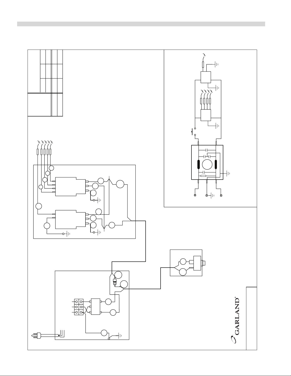
WIRING DIAGRAMS
16GA TEW
(BLK, GRN, RED)
1/4 FEMALE / STRIP 3/8
MODEL
NOMINAL AMPS
(E)GND N L1
GREEN (GND)
BLACK (L1)
WHITE (N)
120V ONLY
(L2)
L1
N(L2)
GND
SCHEMATIC DIAGRAM
SPARK GENERATORS
SWITCH BOX
SPARK ELECTRODES
MOMENTARY SWITCH
GROUND UNUSED
TERMINALS
GROUND UNUSED
TERMINALS
2 x 0.1uf(X2)
2 x 2200pf(Y)
EMI FILTER
2 x 2.0mh
230 VOLT MODELS ONLY
(L2)
MODELS
EMI FILTER
230V
LOAD
LINE
GND
N
(E)
L1
2
NE
3
L
12
NE
3
L
1
0.050.050.1
MISSISSAUGA, ONTARIO, CANADA
COMMERCIAL RANGES LIMITED
SENTRY ELECTRIC SPARK
MODEL
25b
2
1
25a
16
1
2
26
27
28
29
30
30
31
31
25a
25b
3535
27
26
ST28_ E
230V 208V
120V
DRAWN APR/17 2006
2444200
:
DWG
Part # 4519070 Rev 01 (12/07)Page 32
Page 33

WIRING DIAGRAMS Continued
12b
12a
12a
12c
12b
12c
25a
25b
25a
MODEL
KW (h.p.)TOTAL LOADING
(E)GND N L1
GREEN (GND)
BLACK (L1)
WHITE (N)
120V ONLY
(L2)
GREEN
WHITE
BLACK
COOK
OFF
COOL
M~
L1
N(L2)
GND
COOK
COOL
OFF
NO
NC
SWITCH POSITION
DOOR CLOSED
COM
SCHEMATIC
MOTOR
DOOR SWITCH
COOK/COOL SWITCH
BLUE
BLACK
BROWN
GROUND UNUSED
TERMINALS
MOMENTARY SWITCH
SWITCH BOX
2 x 0.1uf(X2)
2 x 2200pf(Y)
EMI FILTER
2 x 2.0mh
230 VOLT MODELS ONLY
(L2)
MODELS
EMI FILTER
230V
LOAD
LINE
GND
N
(E)
L1
1/4 FEMALE /
(BLK, GRN, RED)
16GA TEW
STRIP 3/8
SPARK GENERATORS
3
E
TERMINALS
GROUND UNUSED
N
2 1
L
3
E N
2 1
L
SPARK ELECTRODES
0.4
(1/3)
0.4 3.50.4
(1/3)(1/3)
1.751.8
ST286RCE, ST284RCE, ST283RCE
MODEL
1a
11
10
2a
15
17
11
10
16
1a
2a
15
17
1b
2b
2b
35
28
26
27
29
25b
27
35
26
30
30
31
31
MISSISSAUGA, ONTARIO, CANADA
GARLAND COMMERCIAL RANGES LIMITED
DRAWN APR/17 2006
S(T)28_ RCE
120V 230V 208V
120V
230V 208V
0
1 2
NO
C
NC
2444300
:
DWG
Part # 4519070 Rev 01 (12/07) Page 33
Page 34

WIRING DIAGRAMS Continued
TOTAL LOADING
NOMINAL AMPS
KW (h.p.)
MODEL
(E)GND N L1
(L2)
SWITCHES CONNECTION SIDE
GREEN
MOTOR
BLACK
WHITE
BLACK
GREEN
MOTOR
WHITE
MOMENTARY SWITCH
N
TERMINALS
GROUND UNUSED
L
SPARK ELECTRODES
N LN L
TERMINALS
GROUND UNUSED
SCHEMATIC
DOOR CLOSED
SWITCH POSITION
M~
230 VOLT MODELS ONLY
GND
N(L2)
EMI FILTER
L1
2 x 2.0mh
2 x 2200pf(Y)
2 x 0.1uf(X2)
COOL
OFF
COOK
COOK
COOL
OFF
NC
COM
NO
COM
NO
NC
M~
(BLK, GRN, RED)
FILTER
SOLDER TO
GND
LOAD
N
(L2)
(E)
LINE
L1
16GA TEW
LEFT OVEN
RIGHT OVEN
L1
N(L2)
VIEWED FROM
FRONT
SWITCHES
BLUE
COOL
AMBER
COOK
OFF
BLUE
COOK
AMBER
COOL
OFF
RIGHT OVEN
LEFT OVEN
RIGHT OVEN
LEFT OVEN
BLACK
BLACK
BROWN
BLUE
BLUE
BROWN
(BROWN) (BROWN)
(BLUE) (BLUE)
(2/3)
3.6
0.83
S & STE 283,284RC-2MODEL
16
24 25
17
20
2
1
1
2
6
5
8
7
11
10
12
9
8
7
10
11
21 22
23 3
4
3
30
29
4
14
15
13
16
20
19
26
18
17
21
19 18
24 25
29
30
28
27
12
S/STE28_ RC2 230V
230V 230V
GARLAND COMMERCIAL RANGES LIMITED
MISSISSAUGA, ONTARIO, CANADA
DRAWN APR/17 2006
2574000
NO
C
0
1 2
NC
NC NO
0
1
C
2
:
DWG
Part # 4519070 Rev 01 (12/07)Page 34
Page 35

Part # 4519070 Rev 01 (12/07) Page 35
Page 36

 Loading...