

Page 1
P1GCCB
Series Portable Tap Installation Guide
The portable network TAP is ideal for 10/100/1000MB copper network monitoring. The innovative design
allows this TAP to be easily installed into any copper 10/100/1000 network segment. Once installed in your
network the 10/100/1000 network TAP will enable you to monitor your network segments quickly and
effectively using a network analyzer, security devices, or any monitoring tool. This 10/100/1000 copper TAP
allows you to capture full-duplex traffic without dropping any packets.
This document is for informational purposes only. The information in this document, believed by Garland Technology to be accurate as of the date of publication, is subject to change without notice. Garland
Technology assumes no responsibility for any errors or omissions in this document and shall have no obligation to you as a result of having made this document available to you or based upon the information it
contains. Copyright 2013 © Garland Technology LLC. All Rights Reserved.
+1 716.242.8500 ◊ Buffalo, New York ◊ Garland, Texas ◊ www.garlandtechnology.com
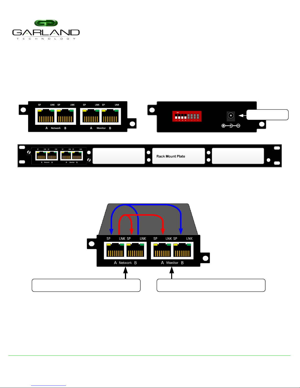
Power Connector
Front View
Back View
RMP-1U: 1U Rack Mount Plate holds up to Four (4) Portable TAPs
Two (2) Live Network Ports
Traffic Flow
The copper 10/100/1000 copper taps provides a copy of the directional traffic out each monitoring port.
Monitor Port A provides you a copy of the A -> B traffic
Monitor Port B provides you a copy of the B -> A traffic
Two (2) Monitoring Ports
PORTABLE TAP KEY FEATURES
· Small portable form factor: 3.942"x1.20"x3.942" (W x H x D)
· Four (4) Copper RJ-45 Ports
· Plug-n-Play design with zero configuration
· Link Speed Synchronization
· Captures Full Duplex Traffic up to 2 Gigabits without dropping any packets
· Jumbo Frames up to 16,383
· Passes physical layer errors
· Rack Shelf supports up to four (4) TAPs in a 1U space
Page 2
P1GCCB
Series Portable Tap Installation Guide
This document is for informational purposes only. The information in this document, believed by Garland Technology to be accurate as of the date of publication, is subject to change without notice. Garland
Technology assumes no responsibility for any errors or omissions in this document and shall have no obligation to you as a result of having made this document available to you or based upon the information it
contains. Copyright 2013 © Garland Technology LLC. All Rights Reserved.
+1 716.242.8500 ◊ Buffalo, New York ◊ Garland, Texas ◊ www.garlandtechnology.com
· Unpack the network TAP
· Configure DIP switches located on the back of the TAP next to the power supply
Note: Anytime the configuration switches are changed the user must remove and then apply power for the changes to take effect.
To deploy the P1GCCB Portable Tap into your network, simply:
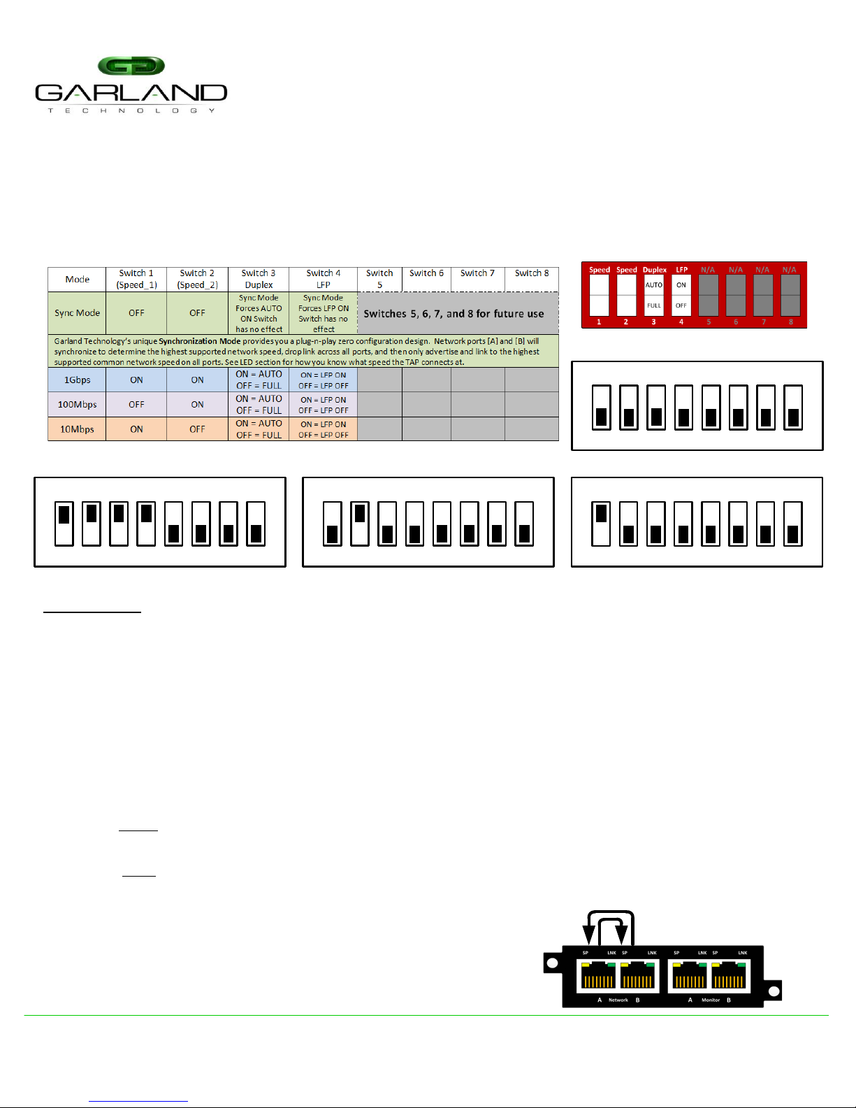
ON
1 82 3 4 5 6 7
1 GIGABIT | AUTO | LFP ON
Configuration Examples
ON
1 82 3 4 5 6 7
1OOMB | FULL | LFP OFF
Definitions:
Synchronization Mode: DIP Switch 1 and 2 in OFF position. When in Synchronization Mode, all ports of the
P1GCCB TAP are Auto MDI/MDIX, Auto Speed and Auto Duplex automatically. The TAP will synchronize to
determine the highest supported network speed, drop link across all ports, and then only advertise and link to
the highest supported common speed on all ports. Places the TAP in full auto mode.
1G, 100M or 10M Speed Mode: (See table for Switch positions) When one of the Speed Settings are selected
then you have to option to select the Duplex (AUTO or FULL) and whether to have LFP turned on or not.
Link Failure Propagation (LFP): Used mostly for HA designed networks. It can sense a network failure and
reflect the failure to the other side of the network allowing the network’s failover mechanism to switch over to
the secondary network path.
Duplex: AUTO setting (Switch 3 in ON position default) lets the port negotiate the duplex mode with the link
pair (only in copper connections).
FULL setting forces the link to full duplex mode
Breakout: An operating mode that allows monitoring of separate traffic streams, one for each direction of
network traffic.
DIP Switch Setup (requires Power Cycle)
ON
1 82 3 4 5 6 7
ON
1 82 3 4 5 6 7
SYNCHRONIZATION | AUTO | LFP
1OMB | FULL | LFP OFF
FailSafe: On power loss, live network tap ports re-establish link
with each other, resuming traffic flow between critical network
devices.
FailSafe Operation
Page 3

P1GCCB
Series Portable Tap Installation Guide
This document is for informational purposes only. The information in this document, believed by Garland Technology to be accurate as of the date of publication, is subject to change without notice. Garland
Technology assumes no responsibility for any errors or omissions in this document and shall have no obligation to you as a result of having made this document available to you or based upon the information it
contains. Copyright 2013 © Garland Technology LLC. All Rights Reserved.
+1 716.242.8500 ◊ Buffalo, New York ◊ Garland, Texas ◊ www.garlandtechnology.com
To deploy the P1GCCB Portable Tap into your network, simply:
· Configure DIP switches on back of TAP (see previous page)
· Install network TAP into the live network
· THIS NEEDS TO BE DONE WITH NO POWER CONNECTED TO THE TAP
· Using two (2) straight through Ethernet cables, connect ports [A] and [B] of the P1GCCB between the
two (2) live network devices where monitoring is desired. Again, with NO POWER to the TAP verify
network traffic is flowing. Traffic will flow with no power to the tap.
· If traffic does not flow, then we need to verify network speeds and duplexing. In 10M and 100M
environments, one (1) straight through cable and one (1) crossover cable maybe required.
· Verify live network is up and running
· Power up the TAP
· Connect ports [C] and [D] of the P1GCCB to the monitoring tools for directional network monitoring
Note: Network Cables MDI/MDIX determines direction of monitor output port
Anytime the configuration switches are changed the user must remove and then apply power for the changes to take effect.
Live
Network
Device 1
Live
Network
Device 2
Monitor
Port B
Monitor
Port A
Network Cabling:
Page 4

P1GCCB
Series Portable Tap Installation Guide
This document is for informational purposes only. The information in this document, believed by Garland Technology to be accurate as of the date of publication, is subject to change without notice. Garland
Technology assumes no responsibility for any errors or omissions in this document and shall have no obligation to you as a result of having made this document available to you or based upon the information it
contains. Copyright 2013 © Garland Technology LLC. All Rights Reserved.
+1 716.242.8500 ◊ Buffalo, New York ◊ Garland, Texas ◊ www.garlandtechnology.com
LED Labeling
When in the Synchronization Mode the SP LEDs will show you what speed has been synchronized for the link.
Below is a diagram and chart showing the LED operations.
SP LED 2
SP LED 4
SP LED 1 Link ActivitySP LED 3
RJ45 Ethernet RJ45 Ethernet
SP or S (Speed): When in Sync Mode only, indicates the highest established common speed across all ports of a
tap. LED’s indicate the following established speeds: [1st SPD 1G] – [2nd SPD 100M] – [3rd SPD 10M] – [4th SPD
Negotiating]
LNK or L (Link/Activity): Solid when link is achieved and flashes when Ethernet activity is detected on a particular
interface.
Ordering Information
P1GCCB Portable 10/100/1000M Copper TAP: 10/100/1000M Copper Network TAP, Single Power Supply,
unique Synchronization Mode, passes data-link layer errors, and Compact Portable footprint
RMP-1U Rack Mount Plate: 1U holds up to four (4) Portable TAPs
RMS-1U Rack Mount Shelf: 1U holds up to four (4) Portable TAPs
 Loading...