

Page 1
P1GXXAS
Portable Tap
Installation Guide
This portable network TAP series is ideal for 10/100/1000MB copper network
monitoring. The innovative design allows these TAPs to be easily installed into any
copper 10/100/1000MB network segment.
Once installed in your network the P1GXXAS network TAPs will enable you to
monitor your network segments quickly and effectively using a network analyzer,
security devices, or any monitoring appliance or tool. These 100/1000MB TAPs will
allow you to capture full-duplex traffic without dropping any packets or, in the
SPAN Mode the input traffic to be replicated to up to 3 monitor ports.
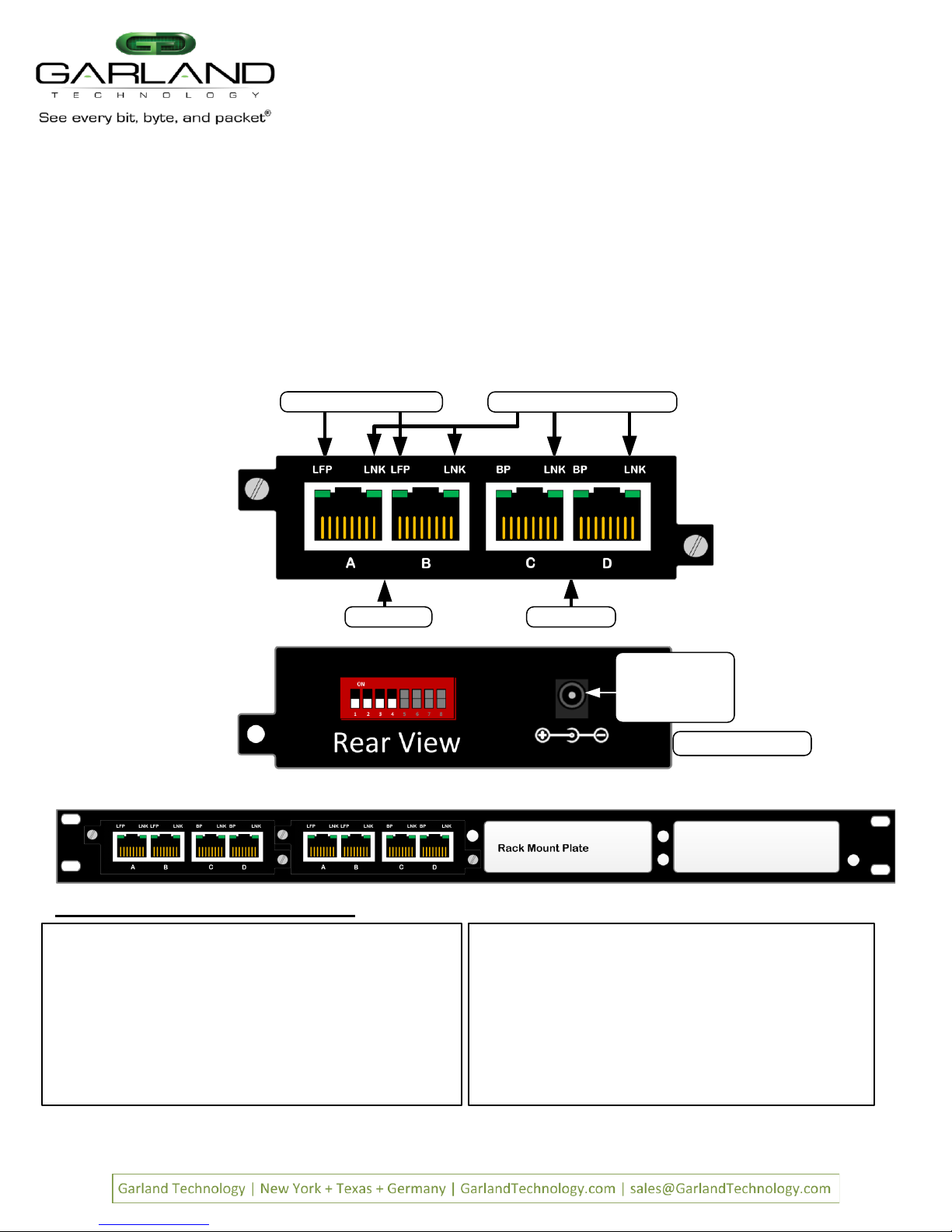
Link Failure Propagation
RJ45 Ethernet RJ45 Ethernet
Link Activity
Power
Connector
Rear View
P1GXXAS TAP Key Features
Supports Breakout, Aggregation and SPAN Modes
Copper media connectivity
Plug-n-Play design with zero configuration
Link Speed Synchronization
Jumbo Frames
Passes physical layer errors on network ports
Supports Link Failu re Propagation (LFP)
Monitor Port Speed selectable (100Mbps or 1Gbps)
Page 1 Ver 4.8
Supports FailSafe in case of power fail ure.
Captures Full Duplex Traffic up to 2 Gigabits without
dropping any packets
Small portable f orm factor: 3.9"x1.15"x6.53" (W x
H x D)
Rack Shelf or Plate supports up to four (4) TAPs in a
1U space
Page 2
P1GXXAS
Portable Tap
Installation Guide (cont)
To deploy the P1GXXAS Portable Tap into your network, simply:
Unpack the device and attach it to an optional rack mount bracket (sold separately)
Install the P1GCCAS assembly into any available 1U slot of a network rack and secure it with rack
mount screws.
Utilizing the DIP switches (located on the reverse side of the unit, next to the power input)
configure the P1GXXAS for the operating mode of your choice (see next page) Install network TAP
into the live network. THIS STEP NEEDS TO BE DONE WITH NO POWER CONNECTED TO THE TAP
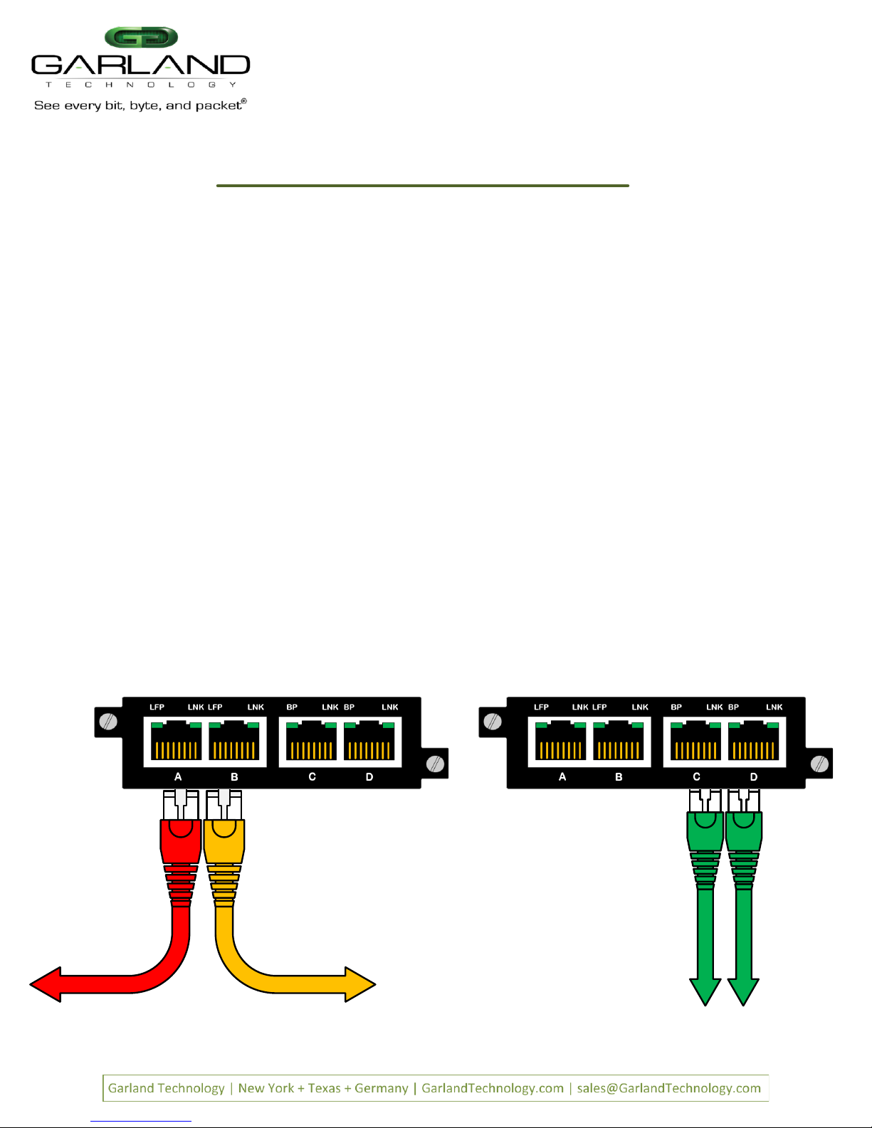
Using standard Ethernet cables, connect ports [A] and [B] (Auto MDIX) of the P1GXXAS between
the two live network devices where monitoring is desired. Verify network traffic is flowing,
confirming that network cabling is correct.
Connect ports [C] and [D] (Auto MDIX) to the monitoring tools for traditional traffic monitoring
(SPAN mode may also be used for regenerating outputs).
Connect the power supply to the P1GXXAS and plug it in to an available power source.
Note: Other operating modes are available for monitoring and may be configured using the
provided DIP switches. Using SPAN or regeneration mode on fiber models may require both [A] and
[B] ports to be connected to obtain link on port [A] or [B].
The BPLED serves no purpose on this model.
Anytime the configuration switches are changed the user must remove and then re-apply power for
the changes to take effect.
Network Cabling:
Live
Network
Device 1
Live
Network
Device 2
Monitor
Port A
Monitor
Port B
Page 2 Ver 4.8
Page 3

P1GXXAS
Portable Tap
Installation Guide (cont)
Configuration Examples
P1GXXAS Portable TAP Operating Modes
Aggregate Mode Breakout Mode SPAN/Regenerate Mode
Network Ports
SYNC
Monitor Ports
Port Sp
Agg regate
Network Ports Monitor Ports
Mon
LFP
1G
OFF
10Mbps
Breakout
Black indicates the position of the switch
UP is on and DOWN is off
Factory Default Settings
Sets Monitor
Port Speed
No
Function
1G
N/A
No
Function
No
Function
Factory Default Setting: Synchronize mode, Aggregation
Mode, Monitor Port Speed 1Gbps and LFP ON
Mon
Port Sp
100M
LFP
OFF
Network Port
1Gbps
Network Failsafe
Network Ports
Monitor Ports
Mon
Port Sp
SPAN
1G
Monitor Ports
LFP
OFF
Definitions
AGG or A (Aggregation): Combines Data Flows
BRE or B (Breakout): Separates Data Flows
LFP (Link Failure Propagation): Allows link state to be mirrored to the adjacent live network
interfaces.
SPAN or S or Regenerate: Allows users to multiply one or more inputs to one or more outputs.
SYNC (Synchronization) Allows link speed synchronization.
N/A (Not Applicable): The N/A DIP Switches have no effect on this product.
Page 3 Ver 4.8
Page 4

Auto Neg
1G only
Auto Neg 1G
Full Duplex
Auto Neg
100M Full
Duplex
Forced
100M Full
Duplex
Auto Neg
10M Full
Duplex
DIP switch Settings
P1GXXAS
Series Portable Tap
Installation Guide (cont)
Sets Monitor
Port Speed
ON
100M
OFF
1G
Forced 10M
Full Duplex
ON
Monito r
Spee d
100M
OFF
Monito r
Spee d
1Gbps
Ordering Information
P1GCCAS Portable 100/1000M Aggregating Tap: Two (2) Copper 100/1000M RJ 45 Tap Ports with two (2) Copper 100M or 1G RJ 45 Monitor
Ports*, single Power Supply supports Breakout Mode, Aggregation Mode, and SPAN Mode
P1GCSAS Portable 100/1000M Aggregating TAP: Two (2) Copper 100/1000M RJ 45 Network Ports with two (2) SFP Monitor Ports*, single
Power Supply supports Breakout Mode, Aggregation Mode, and SPAN Mode
P1GMCAS Portable 1000M Aggregating Tap: Two (2) Multi Mode Passive Fiber LC Tap Ports with two (2) Copper 100M or 1G RJ 45 Monitoring
Ports*, single Power Supply supports Breakout Mode, Aggregation Mode, and SPAN Mode
P1GMSAS Portable 1000M Aggregating Tap: Two (2) Multi mode Passive Fiber LC Tap Ports with two (2) SFP Monitor Ports*, single Power
Supply supports Breakout Mode, Aggregation Mode, and SPAN Mode
P1GSCAS Portable 1000M Aggregating Tap: Two (2) Single Mode Passive Fiber LC Tap Ports with two (2) Copper 100M or RJ 45 Monitor Ports*,
single Power Supply supports Breakout Mode, Aggregation Mode, and SPAN Mode
P1GSSAS Portable 1000M Aggregating Tap: Two (2) Single Mode Passive Fiber LC Tap Ports with two (2) SFP Monitor Ports*, single Power
Supply supports Breakout Mode, Aggregation Mode, and SPAN Mode
RMP-1U Four (4) Slot 1U Rack Mount Plate, holds up to four (4) Portable TAPs
Note * Speed of Monitor Ports is controlled by DIP Sw 6 – ON = 100Mbps, OFF = 1Gbps
This document is for informationa l purposes only . T he information in this document, believed by Gar land Te chnolog y to be accurate as of the da te of publication , is subject to cha nge w ithout notice.
Garland Technology assume s no responsibi lity for any error s or omissions in this docum ent and shall ha ve no obligation to you as a result of having made this document a vailable to y ou or based upon
the information it conta ins. Copyright 2016 Garland T echnology LLC. All rights reserved.
Page 4
+1 716 242 8500 Buffalo, New York Richardson, Texas www.garlandtechnology.com
Ver 4.8
 Loading...