

Page 1
09/18
ATTENTION: Please take a few minutes to thoroughly read this user guide which should be
saved for future reference and passed on to any subsequent owner.
Heat Alarm with Hush User Guide
240V AC 50Hz, 10mA, 9V battery back up, single and or multiple
station (18 units maximum), 57°C temperature rating
Model: OG30
Page 2

Contents of This User Guide
1. Product Features 3
2. Product Specifications
4
3. Installation Instructions
5
4. Locations To Avoid
8
5. Wiring Instructions
8
6. Mounting Instructions
11
7. Operation And Test
12
8. Alarm Nuisance and HUSH
14
9. Troubleshooting
15
10. Battery Replacement
16
11. Cleaning Your Alarm
17
12. Limitations Of Heat Alarms
17
13. Good Safety Habits
18
14. What To Do When the Alarm Sounds
19
15. Warranty & Contact Details
20
Thank you for purchasing this heat alarm. It is an important part of
your family’s home safety plan. You can trust Garland OnGard to
provide the highest quality safety products.
Please take a few minutes to thoroughly read this user guide, and
save it for future reference. Teach children how to respond to the
alarms, and that they should never play with the unit.
If you have any enquiries regarding this product please visit our website:
www.garlandcables.com.au
Page 3

3
1. Product Features
Model OG30 is powered from a 240V AC supply, and has a DC
battery back-up source. AC/DC heat alarms offer added protection
in the event of a power failure. Unique power connector prevents
interconnecting with incompatible heat alarms, CO alarms, smoke
alarms, or security systems. The heat alarms can be interconnected
with up to 17 other Garland OnGard models as set out in Section 2
– Product Specifications. Do not connect to any other type or model
of smoke, CO, or heat alarm.
• Hush feature silences unwanted alarms for up to 10 minutes
• Alarm memory identifies which alarm has activated
• Optional use tamper-resistant feature serves as a safeguard against
tampering
• The heat alarm will sound a short beep about once every
40 seconds if the battery is low
• Multi-purpose green and red LEDs indicate that the heat alarm is
connected to the AC supply, is working normally, or is in alarm
• Loud alarm sounder – 85 dB
• Test button checks heat alarm operation
WARNING! THIS HEAT ALARM IS NOT DESIGNED AS AN
EARLY WARNING TO A FIRE BECAUSE IT DOES NOT DETECT
SMOKE. SEE LIMITATIONS OF THE HEAT ALARM IN SECTION
12 FOR DETAILS.
WARNING! REMOVAL OF HEAT ALARM BATTERY AND
DISCONNECTING OR LOSS OF AC POWER WILL RENDER THIS
UNIT INOPERATIVE.
DO NOT TRY TO REPAIR THIS HEAT ALARM YOURSELF.
Page 4

4
2. Product Specifications
Model OG30
Electrical Rating 240V AC 50HZ, DC battery back up
(9V battery)
Interconnecting Smoke
and Heat Alarms
Up to any combination of 17 other alarm
models. Compatible Models include:
OG10, OG20, OG20LL, OG30.
Temperature Rating
57°C
Maximum Ambient
Temperature Rating
37.8°C
Operating Temperature
0°C TO 40°C
Operating Humidity
Up To 93% Humidity (Non-Condensing)
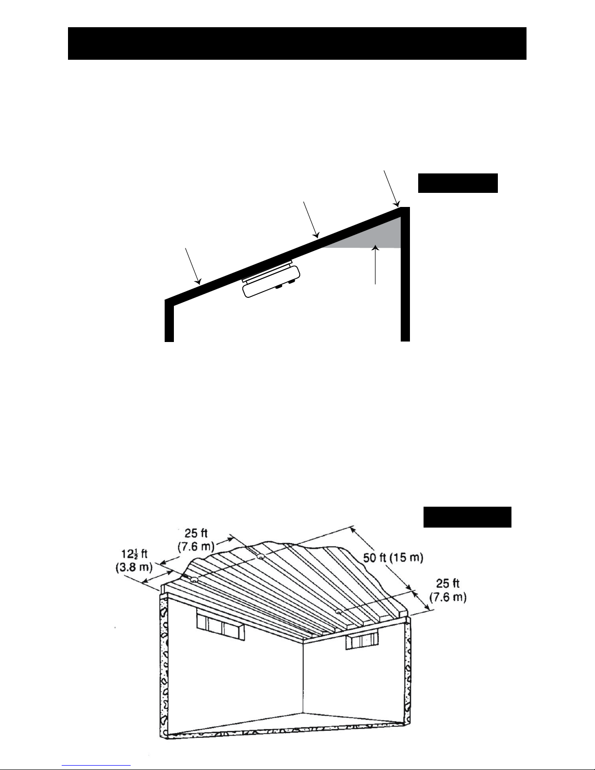
Recommended
Coverage
50m
2
Recommended
Spacing
5.3m
Maximum Distance
From Wall
7.7m
Maximum Ceiling
Height
6m
Page 5
5
3. Recommended Locations
This heat alarm must only be wired to a 240V AC 50Hz sine wave
current supply.
Heat alarms give an audible warning when the temperature at the
alarm reaches 57°C. Heat alarms are ideal for kitchens, garages,
cellars, boiler rooms, attics and other areas where there are normally
high levels of fumes, smoke or dust which preclude the use of smoke
alarms due to the risk of false alarms. Laws on smoke alarms vary from
state to state and you should be aware of what the requirements are
in the state you live - for more information please refer to your local fire
emergency services.
Garland OnGard recommends heat alarms be
installed in addition to legislated smoke alarms in areas where there
might be high air circulation or in areas such as kitchens, bathrooms or
garages where smoke alarms would be subject to higher false alarms.
If, however, the design of the dwelling does not comply with modern fire
safety standards, or if factors such as the presence of several young
children, elderly occupants or disabled people, or smokers, the use of
portable heaters or solid fuel fires during the night, or the use of electric
blankets, particularly by the elderly,
Garland OnGard advises that
additional detection devices, installed within rooms, may be necessary.
The most favourable mounting location for a heat alarm is on the ceiling
and in the centre of the room. At this location, the alarm is closest to
all areas of the room. EXCEPTION: When the mounting surface might
become considerably warmer or cooler than the room, such as a poorly
insulated ceiling, below an unfinished attic, or an exterior wall. In these
cases the alarm should be mounted on an inside wall.
HEAT ALARM
PHOTOELECTRIC ALARM
IONISATION ALARM
ATTIC OFFICE
BEDROOM BEDROOM
LIVING ROOM KITCHEN
UTILITY/
LAUNDRY
GARAGE
• If the alarm cannot be
located in the centre of
the room, an off-centre
location can be used
on the ceiling. When
off-centre mounting an
alarm on the ceiling,
locate it at a minimum of
300mm from the side wall
(FIGURE 2A and 2B).
FIGURE 1
Page 6
6
3. Recommended Locations
FIGURE 2A
CEILING
PEAK CEILING
300mm
MINIMUM
600mm
MINIMUM
MAXIMUM
SIDE WALL
BEST
PLACEMENT
DO NOT INSTALL
DO NOT INSTALL
DEAD AIR
NOT IN THIS AREA
ANYWHERE IN THIS AREA
500mm
1000mm
DEAD AIR
ACCEPTABLE
PLACEMENT
100mm
• If a ceiling mounting location is not possible, the next logical
location for mounting heat alarm is on the side wall. When
mounting the alarm on the wall, use an inside wall with the top
edge of the alarm at a minimum of 100mm and a maximum of
600mm below the ceiling. (see FIGURE 2A)
Page 7
7
3. Recommended Locations
• When mounting the alarm on a sloping ceiling, it should not exceed
1500mm away from the apex. The spacing of additional alarms, if
any, should be based on a horizontal distance measurement, not
a measurement along the slope of the ceiling (see FIGURE 2B)
CEILING
PEAK CEILING
MINIMUM
600mm
MINIMUM
MAXIMUM
SIDE WALL
BEST
PLACEMENT
DO NOT INSTALL
DO NOT INSTALL
DEAD AIR
NOT IN THIS AREA
ANYWHERE IN THIS AREA
500mm
1000mm
DEAD AIR
ACCEPTABLE
PLACEMENT
100mm
FIGURE 2B
DEAD AIR
DO NOT INSTALL
SLOPED CEILING
NOT IN THIS AREA
500mm
ANYWHERE IN THIS AREA
1000mm
• In rooms with open joists or beams,all ceiling mounted alarms shall
be located on the bottom of such beams. (See FIGURE 2C )
• Alarms installed on an open-joist ceiling shall have the smooth
ceiling spacing reduced to no more than half of the listed spacing
when measured at right angles to the solid joist. (See FIGURE 2C)
FIGURE 2C
Page 8

8
3. Recommended Locations
4. Locations to Avoid
Mobile Home Installation:
For Well Insulated Mobile Homes
Install heat alarm as recommended on the previous pages.
In mobile homes that are not well insulated extreme heat or cold can be
transferred from the outside to the inside through poorly insulated walls
and roof. This may create a thermal barrier which can prevent the heat
from reaching an alarm mounted on the ceiling.
For Poorly Insulated Mobile Homes
Install the heat alarm on an inside wall with the top edge of the alarm
at a minimum of 100mm and a maximum of 300mm below the ceiling
(Figure 2A).
For minimum protection, install at least one alarm close to the
bedrooms. For additional protection, see Figure 1.
Warning: test your heat alarm operation after caravan or mobile
home vehicle has been in storage, before each trip and at least
once a week during use.
• In front of forced air supply ducts used for heating and air
conditioning, near ceiling fans, or other high air flow areas.
• In an area where the temperature may fall below 0°C or rise
above 40°C.
• Near fluorescent lights – electronic “noise” may cause nuisance
alarms.
DANGER: ELECTRICAL SHOCK HAZARD. Turn off power
at the main fuse box or circuit breaker by removing the fuse
or switching the circuit breaker to the OFF position and
securing it. An all-pole mains switch with a contact separation
of at least 3mm in each pole shall be incorporated in the
electrical installation of the building.
5. Wiring Instructions
Page 9

9
WARNING: THIS HEAT ALARM MUST BE INSTALLED BY
QUALIFIED (LICENSED) ELECTRICIANS ONLY.
Wiring Requirements
• This heat alarm should be installed with an AS/NZS Wiring Rules
approved junction box. All connections must be installed by
a qualified electrician and be in accordance with the relevant
requirements of the SAA Wiring Rules AS 3000 Standards.
• The appropriate power source is 240V AC 50Hz continuous single
phase sine wave current supplied from a non-switchable circuit
which is not protected by a RCD.
• Heat alarms are not to be used with detector guards unless the
combination (alarm and guard) has been evaluated and found
suitable for that purpose.
•
WARNING: This alarm cannot be operated from power derived
from a square wave or modified square wave inverter. These type
of inverters are sometimes used to supply power to the structure in
off grid installations, such as solar or wind derived power sources.
These power sources produce high peak voltages that will damage
the alarm.
Wiring instructions for AC harness
!
CAUTION! TURN OFF THE MAIN POWER TO THE CIRCUIT
BEFORE WIRING THE ALARM.
• For alarms that are used as single station, DO NOT CONNECT
THE RED WIRE TO ANYTHING. Leave the red wire insulating cap
in place to make certain that the red wire cannot contact any metal
parts or the electrical box.
• When alarms are interconnected, all interconnected units must be
powered from a single circuit.
• A maximum of 18 Garland OnGard AUS safety devices may be
interconnected in a multiple station arrangement. The interconnect
system should not exceed the interconnect limit of 12 smoke alarms
and/or 18 alarms total (smoke, heat detector, etc.).
Page 10

10
5. Wiring Instructions
FIGURE 3
OG20 / OG20LL
Interconnect
Smoke Alarm
OG30
Interconnect
Heat Alarm
OG10
Interconnect
Smoke Alarm
A
N
FUSE OR CIRCUIT BREAKER
Red
A SW
N
Brown
Brown
Brown Brown
Red
Red
Blue
Blue
Blue
Red
Blue
A SW
N
A SW
N
• The maximum wire run distance between the first and last unit
in an interconnected system is 307 meters. Figure 3 illustrates
interconnection wiring. Improper connection will result in damage
to the alarm, failure to operate, or electrical shock hazard.
• Make certain alarms are wired to a continuous (non-switched) final
sub-circuit.
Note: Use approved listed Australian Standards cable 1.0mm²
TPS or larger as required by local codes.
FIGURE 3 “INTERCONNECT WIRING DIAGRAM”
ALARM HARNESS ------------------------ CONNECTED TO:
Brown -------------------------- A (Hot Side of AC Line)
Blue ------------------------- N (Neutral Side of AC Line)
Red ------------------------- SW (Interconnect Lines (Red
Wires) of Other Units in the
Multiple Station Set up)
BATTERY INSTALLATION
See Battery replacement (section 10) for battery installation.
Page 11

11
6. Mounting Instructions
CAUTION! THE BATTERY TAMPER BUTTON MUST BE HELD
DOWN IN THE BATTERY COMPARTMENT BY THE BATTERY,
TO ENSURE THE BATTERY DOOR WILL CLOSE, THE AC QUICK
CONNECTOR WILL ATTACH TO THE ALARM, AND THE ALARM
WILL ATTACH TO THE TRIM RING.
NOTE: PLEASE ENSURE THAT BATTERY IS INSTALLED PRIOR
TO MOUNTING OF HEAT ALARM.
A trim ring is provided on the back of the heat alarm. This trim ring is
removed by holding the trim ring and twisting the heat alarm in the
direction indicated by the TURN TO REMOVE arrow. The trim ring is
secured to the heat alarm by a trim lever.
CAUTION ! THE COVER IS A SEALED UNIT AND HAS NO
REMOVABLE SERVICEABLE PARTS! DO NOT TAMPER.
1. Secure a suitable junction box near the position of the heat alarm,
ensure the quick connect cable
length is long enough to reach
the junction box for termination
to be made.
2. Connect active, neutral and switch
line to the heat alarm cable using
the terminal connection block
provided. Secure these terminals
inside the junction box.
3. Punch out the suitable fixing holes
on the trim ring and then pull the
AC connector through the centre
of the trim ring.
4. Secure the trim ring to the ceiling
using the fixing holes provided.
Connect the 9V battery (back up)
into the battery compartment. If
the back up 9V battery is already
loaded in the battery compartment,
pull out the battery pull tab. Ensure
the locks on the AC connector
snap firmly into place.
SQUEEZE
CONNECTOR
LOCKING
ARMS AND PULL
INSTALL
MARKS
REMOVE
FIGURE 4A
FIGURE 4B
Page 12

12
7. Operation and Test
The heat alarm is operating once AC power is applied, new battery
is installed and testing is complete. When the heat alarm senses
temperatures above 57°C (plus or minus a few degrees), the horn
will sound a loud (85 db) pulsating alarm.
RED AND GREEN LED INDICATORS:
This heat alarm features a red and green LED indicator that can
be seen through the clear light pipe on the top of alarm. The LEDs
indicate the following:
GREEN
ON – AC power is present.
OFF – AC power is not present.
RED
Red LED blinks once every 5 minutes and 20 seconds
– Mains power is present indicating normal operation.
Red LED blinks once every 10 seconds
– False Alarm Control activated.
Red LED OFF
– DC power is not present.
Red LED blinks once a second and unit is sounding alarm
– Senses 57°C temperature or greater.
Red LED OFF and unit is sounding alarm
– Another interconnected smoke/heat alarm in the network has
sensed smoke or 57°C temperature and is signalling this alarm.
Red LED is 3 rapid flashes at 40 second interval
– Indicates which alarm has previously detected an alarm
condition.
5. Now mount the heat alarm onto the trim ring. Rotate the heat alarm
until the heat alarm snaps firmly into place.
Switch on the AC power and the green AC power ‘ON’ indicator
should be lit. The heat alarm is now operating on mains power.
Page 13

13
7. Operation And Test
TESTING THE HEAT ALARM
Warning: test each heat alarm and smoke alarm to be sure
that each is installed correctly and is operating properly.
Stand at arm’s length from the heat alarm when testing. The alarm
sounder is loud to alert you to an emergency and can be harmful to
hearing.
Test the heat alarm weekly and upon returning from holiday, or when
the house has been unoccupied for several days.
Test all heat alarms weekly by doing the following:
1. Check the Hush/Test button. If the green LED above the test button
is ON, the heat alarm is receiving AC power.
2. Firmly depress and hold the Hush/Test button for at least five (5)
seconds. The heat alarm will sound 3 long beeps, pause, 3 longs
beeps, repeating for up to 10 seconds after the Hush/Test button
is released. NOTE: If heat alarms are interconnected, all heat and
smoke alarms should sound an alarm within three (3) seconds after
any test button is pushed and the tested heat alarm sounds.
3. If the heat alarm does not sound, please refer to Section 9:
Troubleshooting. If this doesn’t work please contact your
electrician.
Warning: If the heat alarm sounds, and the heat alarm
is not being tested, the heat alarm is sensing a temperature
of 57°C or above. THE ALARM SOUND REQUIRES YOUR
IMMEDIATE ATTENTION AND ACTION. EVACUATE THE
DWELLING IMMEDIATELY!
Page 14

14
8. Alarm Nuisance And HUSH
Heat alarms respond only to heat. They do not detect smoke. If the
alarm does sound, check for fires first. If a fire is discovered, get out
of the house and call the fire brigade. If no fire is present, check to see
if one of the reasons listed in Section 4 may have caused the alarm.
HUSH
The Hush feature will silence the alarm for approximately 10 minutes.
After 10 minutes the heat alarm will revert to normal operation. If the
unit still detects a dangerous situation the alarm will sound again.
A rapid rise in temperature will override the False Alarm Control and
cause the unit to sound an alarm.
If interconnected alarms are installed, the unit that detects the high
temperature and sounds the alarm cannot be inadvertently silenced
by the Hush/Test button of other units. In this case all of the alarms will
continue to sound for as long as a dangerous situation is detected or
until the Hush/Test button of the initiating alarm is pressed.
If the alarm does not go into False Alarm Control and continues to
sound its alarm, the heat in the area is too high and a dangerous
situation may exist – take emergency action.
Warning: Before using the alarm’s Hush feature, fully
identify the source of the heat build up and make sure that
the area is safe. To activate control push and release the
test/false alarm control button in the center of the alarm.
The alarm will silence immediately and the red light (LED) will
blink approximately every 10 seconds for the next 10 minutes.
This feature is to be used only when a safe condition is known
to exist.
Page 15

15
9. Troubleshooting
PROBLEM SOLUTION
Heat alarm does not
sound when tested.
NOTE: Push and hold
test button for at least
five (5) seconds while
testing!
1. Check that AC power is turned on.
2. Turn off power. Remove heat alarm
from mounting plate and:
a. check that connector plug is securely
attached.
b. Check that Section 10 Battery is
installed correctly.
3. Clean heat alarm.
Heat alarm beeps about
once every 40 seconds
Turn off AC power, replace battery and
Clean alarm. See “Section 10 Battery
Replacement” and “Section 11 Cleaning
Your Alarm”
Heat alarm sounds
unwanted alarms.
1. Hire an electrician to move heat alarm
to a new location.
See “Section 3 Installation Instructions”
and “Section 4 Locations to Avoid”
Interconnected heat
alarms do not sound
when system is tested.
1. Press and hold button for at least five
(5) seconds after the first unit sounds.
2. Turn off AC power or circuit breaker
and check the interconnect wiring.
See “Section 5 Wiring instructions”.
3 chirps every
40 seconds
1. Before 10 years of operation: unit is in
fault mode. Contact customer service.
2. After 10 years of operation: end of
life warning. Alarm must be replaced
(REPLACE IMMEDIATELY!)
NOTE: Visit our website: www.garlandcables.com.au, if your alarm
does not seem to operate correctly.
Page 16

16
10. Battery Replacement
Alarm Removal
To replace the battery, remove the alarm from the trim ring by rotating
the alarm in the direction of the “OFF” arrow on the cover (See
section 6, Figure 4B). To disconnect the AC power harness, squeeze
the locking arms on the sides of the Quick Connector while pulling
the connector away from the bottom of the alarm (See Section 6,
Figure 4A).
Battery Installation and Replacement:
To replace or install the battery you must first remove the alarm from
the trim ring by following the ALARM REMOVAL instructions at the
beginning of this section. After the alarm has been removed you can
open the battery door and install or replace the battery. Install the
battery to the battery terminal clip of the heat alarm. When installing
the battery, press the battery lever down into the battery compartment
and install the battery. (See Figure 5).
CAUTION ! If the battery compartment is closed without
a battery, the red battery tamper will prevent the heat alarm
from attaching to the trim ring.
USE ONLY THE FOLLOWING 9VOLT BATTERIES FOR HEAT
ALARM REPLACEMENT:
Alkaline type: ENERGIZER 522; DURACELL MN1604 or MX1604
Lithium type: ULTRALIFE U9VL-J
NOTE: REGULAR WEEKLY TESTING IS RECOMMENDED
WARNING! Use only the batteries specified. Use of
different batteries may have a detrimental effect on the alarm.
Exposure to temperature extremes and / or high humidity may
reduce battery life.
Battery door
FIGURE 5
Page 17

17
11. Cleaning Your Alarm
YOUR ALARM SHOULD BE CLEANED AT LEAST ONCE A YEAR
To clean your alarm, remove it from the mounting bracket as outlined
in Section 10 Battery Replacement or Section 6, Figure 4A. You can
clean the interior of your alarm (sensing chamber) by using compressed
air or a vacuum cleaner hose and blowing or vacuuming through the
openings around the temperature sensor located on the top of the
alarm. The outside of the alarm can be wiped with a damp cloth.
After cleaning, reinstall your alarm and test your alarm by using the test
button. If cleaning does not restore the alarm to normal operation the
alarm should be replaced.
After cleaning, reinstall your alarm. Test your alarm by using the
test button and check that the green LED is on.
12. Limitations Of Heat Alarms
WARNING! Heat alarms are not designed to protect life
safety against fire and smoke. In most fires, hazardous
levels of toxic gases, smoke and heat can build up before
a heat alarm will operate. In cases where life safety is an
issue, heat alarms should only be used to provide an added
source of information and as a supplement to the smoke
alarm installation. Heat alarms do not always detect fires,
the fire may be a slow smoldering (smoke producing) low
heat producing type, the fire may be in a different room than
the alarm, or the heat from the fire may bypass the alarm.
This alarm will not detect smoke, gases or flames.
• Subject to applicable legal requirements in each State and Territory,
Garland OnGard recommends that both ionisation and photoelectric
smoke alarms be installed to help insure maximum detection of the
various types of fires that can occur within the home. Ionisation
sensing alarms may detect invisible fire particles (associated with
fast flaming fires) sooner than photoelectric alarms. Photoelectric
sensing alarms may detect visible fire particles (associated with
slow smouldering fires) sooner than ionisation alarms.
• Heat alarms cannot provide an alarm if heat does not reach the
alarm. Therefore, heat alarms may not sense fires starting in
chimneys, walls, on roofs, on the other side of a closed door or
on a different floor. If the alarm is located outside the bedroom or
on a different floor, it may not wake up a sound sleeper. The use
Page 18

18
12. Limitations Of Heat Alarms
of alcohol or drugs may also impair ones ability to hear the alarm.
For maximum protection heat alarms should only be used as a
supplement to smoke alarms. Smoke alarms should be installed in
each sleeping area on every level of a home and be interconnected
with each other and the heat alarms.
• Although heat alarms when combined with smoke alarms, can help
save lives by providing an early warning of a fire, they are not a
substitute for an insurance policy. Home owners and renters should
have adequate insurance to protect their lives and property.
13. Good Safety Habits
DEVELOP AND PRACTICE A PLAN OF ESCAPE:
• Install and maintain fire extinguishers on every level of the home
and in the kitchen, basement and garage. Know how to use a fire
extinguisher prior to an emergency.
• Make a floor plan indicating all doors and windows and at least
two (2) escape routes from each room. Second story windows may
need a rope or chain ladder.
• Have a family meeting and discuss your escape plan, showing
everyone what to do in case of fire.
• Determine a place outside your home where you all can meet if a
fire occurs.
• Familiarise everyone with the sound of the alarm and train them to
leave your home when they hear it.
• Practice a fire drill at least every six months, including fire drills at
night. Ensure that small children hear the alarm and wake when it
sounds. They must wake up in order to execute the escape plan.
Practice allows all occupants to test your plan before an emergency.
You may not be able to reach your children. It is important they
know what to do.
• Current studies have shown alarms may not awaken all sleeping
individuals. It is the responsibility of individuals in the household that
are capable of assisting others to provide assistance to those who
may not be awakened by the alarm sound, or to those who may be
incapable of safely evacuating the area unassisted.
Page 19

19
14. What To Do When The Alarm Sounds
• Leave immediately by your escape plan. Every second counts,
so don’t waste time getting dressed or picking up valuables.
• In leaving, don’t open any inside door without first feeling its
surface. If hot, or if you see smoke seeping through cracks, don’t
open that door! Instead, use your alternate exit. If the inside of the
door is cool, place your shoulder against it, open it slightly and be
ready to slam it shut if heat and smoke rush in.
• Stay close to the floor if the air is smoky. Breathe shallowly through
a cloth, wet if possible.
• Once outside, go to your selected meeting place and make sure
everyone is there.
• Call the fire department from your neighbour’s home - not from
yours!
• Don’t return to your home until the fire officials say that it is all right
to do so.
Page 20

20
15. Warranty & Contact Details
TEN YEAR WARRANTY
Warranty
Garland warrants to the original consumer purchaser (Customer) that
each new heat alarm will be free from defects in materials and
workmanship under normal use for a period of 10 years from the date
of purchase (Warranty Period). To the extent permitted by law, Garland
agrees to repair or replace (at our discretion) any defective product, within
the Warranty Period, on presentation of proof of purchase.
Australia warranty claims:
1. These Terms outline how the Company warrants our products for
all Products purchased after 1 January 2011.
2.
Garland
warrants that all
Garland
Products (excluding Third Party
Product) will operate in accordance with their published specifications
for the duration of the Warranty Period.
3. Where the sale of Products is to electrical wholesale customers of
Garland
, no additional warranties are to be provided on behalf of
Garland
to end consumers.
4. The Australian Consumer Law (ACL) protects consumers by giving
them certain rights relating to the purchase of goods and services.
5. If the Customer is a ‘consumer’ as the term is defined in the ACL:
5.1
Garland
’s Products come within guarantees that cannot
be excluded under the ACL;
5.2 The Customer is entitled to a replacement or refund for major
failure and for compensation for other reasonably foreseeable
loss or damage;
5.3 The Customer is entitled to have the Products repaired or
replaced if the Products fail to be of acceptable quality and the
failure does not amount to a major failure.
6. In addition, the Customer must ensure that terms of a like nature
are contained in any contract of sale or onsale of the Products to a
Third Party purchaser.
7. The Customer indemnifies and holds
Garland
harmless from any
claims or demands which are made as a result of their failure to comply
with the requirements of this clause.
8. If the Customer makes a claim during the Warranty Period it will be
handled as follows:
(a) In the case of
Garland
Products, where there is a defect in such
Products,
Garland
will replace or repair the Products (at its
discretion and cost).
(b)
Garland
will not be responsible for the cost of retrieving,
removing, reinstalling, or retesting the Products to and from the
location where the Products are located.
(c) All warranties for any Products repaired or replaced during the
Warranty Period will expire at the same time as the original
warranty of the Products that were repaired or replaced.
Page 21

21
Exclusions
Subject to non-excludable laws, this warranty does not cover:
• normal wear and tear to the product or parts
• batteries or other consumables included with this product (excluding
sealed non replaceable battery models)
• damage to the product caused by or at the direction of the Customer,
including through accident, misuse, abuse, lack of reasonable care,
tampering or repair by uncertified or non-authorised personnel.
• any product that has not been installed, operated or maintained in
accordance with the manual or operating instructions provided with
the product
• any damage caused by improper power input or improper cable
connection
• any indirect, special or consequential loss or damage of any kind
Garland’s total liability in relation to the products shall not exceed the
purchase price paid for the products, regardless of the basis of the claim
and whether or not arising due to or in connection with the supply.
To make a claim
If a defect in the product appears within the Warranty Period, you
are entitled to submit a warranty claim by first visiting the Garland
website address below and filling out the Return Form.
On contacting Garland and providing the proof of purchase (The
original number and date of invoice) you will be issued a Goods
Return Authorisation (GRA) prior to you returning the product.
When returning the product please ensure a copy of the GRA is
included and the product is properly packaged so that no damage
occurs in transit. Any postage and packaging expenses required to
return the product to Garland will be at your cost, but you may be
entitled to a refund of those postage and packaging expenses where
there is a major or minor problem with the products which entitles you
to a repair or replacement.
If Garland elects to repair the product, please note that the products
presented for repair may be replaced by refurbished goods of the
same type rather than being repaired. Refurbished parts may be
used to repair the products, where such parts are equivalent quality
to the original.
15. Warranty & Contact Details
Page 22

This warranty is provided by:
Madison Technologies
149 Beaconsfield St, Silverwater NSW 2128
1800 66 99 99
www.garlandcables.com.au
ABN 56 010 669 379
 Loading...