

Page 1

INSTALLATION AND
OPERATION MANUAL
GARLAND GAS & ELECTRIC
CLAMSHELL GRILLS
WITH PRODUCT RECOGNITION
MODELS:
MWE3W
MWE3S
MWG3W
WARNING:
IMPROPER INSTALLATION, ADJUSTMENT, ALTERATION, SERVICE OR MAINTENANCE CAN CAUSE
PROPERTY DAMAGE, INJURY OR DEATH. READ THE INSTALLATION, OPERATING AND MAINTENANCE
INSTRUCTIONS THOROUGHLY BEFORE INSTALLING OR SERVICING THIS EQUIPMENT.
PLEASE READ ALL SECTIONS OF THIS MANUAL AND RETAIN FOR FUTURE REFERENCE.
THIS EQUIPMENT MUST BE INSTALLED AND COMMISSIONED BY A PROFESSIONAL,
FACTORY-TRAINED TECHNICIAN.
THIS EQUIPMENT MUST BE OPERATED UNDER AN APPROVED HOOD SYSTEM ONLY.
NOTE: This manual pertains to all grill models listed above. The reader/operator must interpret its contents
to applicable needs. If you have questions about any instructional materials pertaining to Garland grills,
please contact our Customer Service Department at one of the phone numbers below.
MANUFACTURED EXCLUSIVELY FOR McDonald's BY
GARLAND COMMERCIAL INDUSTRIES, LLC
185 EAST SOUTH STREET FREELAND, PENNSYLVANIA 18224
TOLL FREE: (800) 446-8367 PHONE: (570) 636-1000 FAX: (570) 636-9874
E-mail: clamshell@garland-group.com
http://www.garland-group.com
PART #4521777 (03/30/10)
Page 2

Page 3

GARLAND CLAMSHELL GRILLS WITH PRODUCT RECOGNITION INSTALLATION/OPERATION MANUAL
CONTENTS
INTRODUCTION. . . . . . . . . . . . . . . . . . . . . . . . . . . . . . . . . . . . 4
WARRANTY. . . . . . . . . . . . . . . . . . . . . . . . . . . . . . . . . . . . . . . . 4
SAFETY. . . . . . . . . . . . . . . . . . . . . . . . . . . . . . . . . . . . . . . . . . . . 5
SHIPPING DAMAGE CLAIM PROCEDURE . . . . . . . . . . . . . 6
CLEANING & MAINTENANCE. . . . . . . . . . . . . . . . . . . . . . . . 6
SPECIFICATIONS . . . . . . . . . . . . . . . . . . . . . . . . . . . . . . . . . . 10
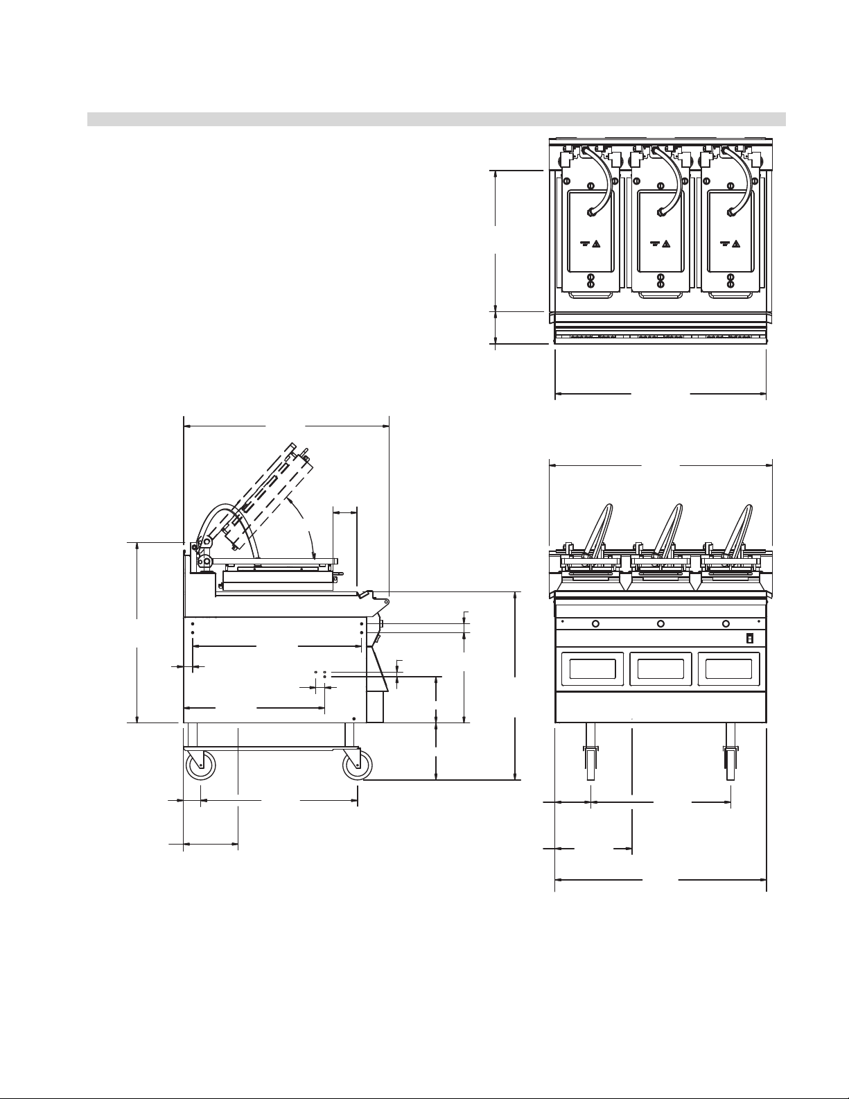
Dimensions: Model MWE3S. . . . . . . . . . . . . . . . . . . . . . . . . . . . . . . .11
Input Specications, Electric Grills, United States: . . . . . . . . . . .12
Input Specications, Electric Grills, Canada: . . . . . . . . . . . . . . . . .12
Input Specications, Electric Grills, CE Approved . . . . . . . . . . . .12
Input Specications, Electric Grills, Export, Non-CE . . . . . . . . . .12
Input Specications, GAS Grills, North America: . . . . . . . . . . . . . 13
Input Specications, GAS Grills, CE Approved . . . . . . . . . . . . . . .13
INSTALLATION & STARTUP. . . . . . . . . . . . . . . . . . . . . . . . . 14
Exhaust hood Type & Platen Height. . . . . . . . . . . . . . . . . . . . . . . . . 17
Startup Procedure . . . . . . . . . . . . . . . . . . . . . . . . . . . . . . . . . . . . . . . . .18
INSTALLATION OF WRAP AROUND RELEASE MATERIAL
MOUNTING BRACKETS . . . . . . . . . . . . . . . . . . . . . . . . . . . . 19
INSTALLATION OF SPLASH SHIELD . . . . . . . . . . . . . . . . . 19
INSTALLATION OF RELEASE MATERIAL. . . . . . . . . . . . . . 20
INSTALLATION OF VAPOR SHIELD . . . . . . . . . . . . . . . . . . 20
AVAILABLE ACCESSORIES. . . . . . . . . . . . . . . . . . . . . . . . . . 21
Splash Shield . . . . . . . . . . . . . . . . . . . . . . . . . . . . . . . . . . . . . . . . . . . . . .21
Vapor Shield . . . . . . . . . . . . . . . . . . . . . . . . . . . . . . . . . . . . . . . . . . . . . . .21
Teon Wraparound kits. . . . . . . . . . . . . . . . . . . . . . . . . . . . . . . . . . . . . 21
Quick Disconnect Gas Hose . . . . . . . . . . . . . . . . . . . . . . . . . . . . . . . . 22
Interlock Cord - 5-Wire . . . . . . . . . . . . . . . . . . . . . . . . . . . . . . . . . . . . .22
3Phase 4Wire 50 AMP Cord. . . . . . . . . . . . . . . . . . . . . . . . . . . . . . . . .22
3Phase 4 Wire 30 AMP Cord . . . . . . . . . . . . . . . . . . . . . . . . . . . . . . . .22
DESCRIPTION OF GRILL CONTROL. . . . . . . . . . . . . . . . . . 23
POSSIBLE ERROR MESSAGES. . . . . . . . . . . . . . . . . . . . . . . 23
OPERATING PROCEDURES . . . . . . . . . . . . . . . . . . . . . . . . . 24
General Overview: . . . . . . . . . . . . . . . . . . . . . . . . . . . . . . . . . . . . . . . . .24
To turn the grill on:. . . . . . . . . . . . . . . . . . . . . . . . . . . . . . . . . . . . . . . . . 24
To Select a Menu item: . . . . . . . . . . . . . . . . . . . . . . . . . . . . . . . . . . . . . 24
Menu Item Library . . . . . . . . . . . . . . . . . . . . . . . . . . . . . . . . . . . . . . . . .24
Indicator Lights . . . . . . . . . . . . . . . . . . . . . . . . . . . . . . . . . . . . . . . . . . . . 25
Standby Mode . . . . . . . . . . . . . . . . . . . . . . . . . . . . . . . . . . . . . . . . . . . . .25
To display the current temperatures:. . . . . . . . . . . . . . . . . . . . . . . .25
Breakfast In Manual mode. . . . . . . . . . . . . . . . . . . . . . . . . . . . . . . . . . 25
Lunch In Manual mode. . . . . . . . . . . . . . . . . . . . . . . . . . . . . . . . . . . . .25
To Change The Cook Time for a Menu Item. . . . . . . . . . . . . . . . . .25
Breakfast In Auto mode . . . . . . . . . . . . . . . . . . . . . . . . . . . . . . . . . . . . 25
Lunch In Auto mode . . . . . . . . . . . . . . . . . . . . . . . . . . . . . . . . . . . . . . . 26
Transition Cooking . . . . . . . . . . . . . . . . . . . . . . . . . . . . . . . . . . . . . . . . . 26
PRODUCT RECOGNITION . . . . . . . . . . . . . . . . . . . . . . . . . . 26
TO PERFORM FORCED AUTO CALIBRATION. . . . . . . . . . . . . . . . . . 26
COMMON PRODUCT RECOGNITION ISSUES . . . . . . . . . 27
PATTY PLACEMENT . . . . . . . . . . . . . . . . . . . . . . . . . . . . . . . 28
PROGRAM LOGIC . . . . . . . . . . . . . . . . . . . . . . . . . . . . . . . . . 29
CONTROL PROGRAMMING . . . . . . . . . . . . . . . . . . . . . . . . 30
Programming Modes; System Setup . . . . . . . . . . . . . . . . . . . . . . . .30
Programming Modes; Menu Items. . . . . . . . . . . . . . . . . . . . . . . . . .31
PROBE CALIBRATION . . . . . . . . . . . . . . . . . . . . . . . . . . . . . . 34
THERMOCOUPLE LOCATIONS . . . . . . . . . . . . . . . . . . . . . . 34
FACTORY DEFAULT SETTINGS . . . . . . . . . . . . . . . . . . . . . . 35
PART #4521777 (03/30/10)
Page 3
Page 4

INSTALLATION/OPERATION MANUAL GARLAND CLAMSHELL GRILLS WITH PRODUCT RECOGNITION
INTRODUCTION
The Garland clamshell grill, manufactured exclusively for McDonald’s, provides a method for ecient two-sided cooking,
while accommodating a variety of products. The unit will also serve as a at grill, and meets all of McDonald’s standards for
safety, eciency, and cleanliness.
WARRANTY
This warranty covers defects in material and workmanship under normal use providing that:
a) the equipment has not been accidentally or intentionally damaged, altered or misused.
b) the equipment is properly installed, adjusted, operated and maintained in accordance with national and local
codes and in accordance with the installation instructions provided with this product.
c) the warranty serial number axed to the appliance by us has not been defaced, obliterated or removed.
d) an acceptable report for any claim under this warranty is supplied to us.
The equipment warranty coverage remains in force for two (2) years, (parts and labor), from the date the equipment is put
into operation.
The Garland Group agrees to repair or replace, at it’s option, any part that proves to be defective in material or
workmanship at no charge for the part or normal labor.
We assume no responsibility for installation, adjustments, diagnosis, or normal maintenance such as: lubrication of springs
or valves. We exclude failures caused by erratic voltage or gas supplies.
We assume no responsibility for travel costs beyond 100 miles round trip, travel other than overland, and overtime
costs of repair.
We exclude broken glass, paint and porcelain nish, surface rust, gasket material, ceramic material, light bulbs and
fuses from normal coverage.
We exclude damage or dysfunction caused by re, ood, and like “Acts of God” that are beyond the control of The
Garland Group.
The Garland Group’s liability on a claim of warranty shall not exceed the price of the material and/or service, which caused
the claim.
This warranty is limited and is in lieu of all other warranties, expressed or implied. The Garland Group, our employees,
or our agents shall not be held liable for any claims of personal injury or consequential damage or loss.
This warranty gives you specic legal rights, and you may have other rights which vary from state to state.
PART #4521777 (03/30/10)Page 4
Page 5

GARLAND CLAMSHELL GRILLS WITH PRODUCT RECOGNITION INSTALLATION/OPERATION MANUAL
SAFETY
THIS APPLIANCE IS FOR PROFESSIONAL USE AND SHALL BE USED ONLY BY QUALIFIED PERSONNEL.
WARNING: Accessible parts may become hot during use. Young children should be kept away. This appliance is not intended for
use by persons (including children) with reduced physical, sensory or mental capabilities, or lack of experience and knowledge,
unless they have been given supervision or instruction concerning use of the appliance by a person responsible for their safety.”
CAUTION: THIS EQUIPMENT MUST ONLY BE OPERATED UNDER AN APPROVED HOOD SYSTEM IN ACCORDANCE WITH
LOCAL REGULATIONS IN FORCE.
DO NOT OPERATE THE GRILL UNLESS IT HAS BEEN COMMISSIONED (START-UP) BY A FACTORY AUTHORIZED SERVICE CENTER.
DO NOT operate the grill without reading this operation manual.
DO NOT operate the clamshell grill unless it has been properly installed and grounded.
DO NOT operate the clamshell grill unless all service and access panels are in place and fastened properly.
Means of disconnection, must be incorporated in the xed wiring in accordance with local wiring rules (such as a switch, fuse,
or circuit breaker). External equipotential bonding conductor provided on rear of appliance. Use as applicable, in accordance with
local wiring rules.
The Garland clamshell grill is a semi-automatic cooking appliance. The upper platen is lowered automatically, following the
manual, single-handed initiation of the cooking cycle, and raised automatically upon completion of the cooking cycle.
When two sided cooking, the area between the upper platen and the griddle plate should be regarded as a “danger zone”.During two sided cooking the operator must not be within this danger zone. When used as a at grill, then this area is no longer
a danger zone, the platens do not move. For whatever reason, be it cleaning, maintenance, normal operation, any exposed
person must use extreme caution if within this danger zone. Temperatures on solid cooking surfaces are intended to operate
above 120C (250F).
In two sided cooking the upper platen remains in the lowered position by nature of it’s own weight. It is not locked down. It
can be raised by lifting of the handle on the front of the platen, which pivots the platen about its rear mounting point.
The clamshell grill must only be used for single and two sided cooking of foodstus in a McDonald’s store.
WARNING: To avoid serious personal injury: DO NOT attempt to repair or replace any part of the clamshell grill unless all main
power supplies to the grill have been disconnected.
USE EXTREME CAUTION in setting up, operating and cleaning the clamshell grill to avoid coming in contact with hot grill
surfaces or hot grease. Suitable protective clothing should be worn to prevent the risk of burns.
WARNING: This appliance must not be cleaned with a water jet. DO NOT apply ice to a HOT grill surface.
NOTE: All warning labels and markings on the grill, which call attention to further dangers and necessary precautions.
HAZARD COMMUNICATION STANDARD, (HCS) - The procedures in this manual include the use of chemical products. These
chemical products will be printed in bold face, followed by the abbreviation (HCS) in the text portion of the procedure. See
the Hazard Communication Standard, (HCS) manual for the appropriate Material Safety Data Sheet(s), (MSDS).
WARNING: After turning the master power switch to the START position, the grill will go through an initialization process. If
the upper platens are in the lowered position they will return to their raised upper position.
MAINTENANCE - the platen support arms carriage block bearing bushes, the platen adjuster nuts, the platen support (shoulder)
bolt and the cam follower should be checked annually for wear. Should there be any noticeable play in the bearing bushes and
any visible wear on the platen adjuster nuts, platen support bolts or cam follower, then they must be replaced.
MAINTENANCE - the audible alarm that sounds at the end of a cook cycle is to advise the operator that the platen is about
to move. The function of this device may be tested by pushing the left hand CANCEL button. If no sound is heard, ensure that
the alarm volume is not set to low in SYSTEM SETUP. If there is still no sound then a service engineer should be called out to
rectify the fault.
SERVICE AND CLEANING - The grill may be secured in the grill bay by the installer using two anchors that lock onto the front
casters. If the grill is to be moved out of the bay for cleaning or service, remove the anchor from each caster by turning the knob
counterclockwise to loosen the retainer. When the retainer is free of the caster, lay the assembly aside on the oor.
CLEANING - NEVER clean the grill, interior or exterior, using a high-pressure sprayer, water jet, or any other liquid sprayer.
NOTE: If anchors are present, the anchor assembly remains fastened to the back wall of the grill bay. After service or clean-
ing is complete, return the grill to its position in the bay and reattach the anchors by placing the retainer on the caster post
and turning the knob clockwise to tighten. For safety reasons, the grill must be secured in the grill bay in this manner before
operation can resume.
PART #4521777 (03/30/10)
Page 5
Page 6

INSTALLATION/OPERATION MANUAL GARLAND CLAMSHELL GRILLS WITH PRODUCT RECOGNITION
1
2
3
4
SHIPPING DAMAGE CLAIM PROCEDURE
Please note that the Garland equipment was carefully inspected and packed by skilled personnel before leaving the
factory. The transportation company assumes full responsibility for safe delivery upon acceptance of the equipment. What
to do if the equipment arrives damaged:
1. File a claim immediately regardless of the extent of damage.
2. Be sure to note, “visible loss or damage,” on the freight bill or express receipt and have the person making the delivery
sign it.
3. Concealed loss or damage: if damage is unnoticed until the equipment is unpacked, notify the freight company
immediately, (within 15 days), and le a concealed damage claim.
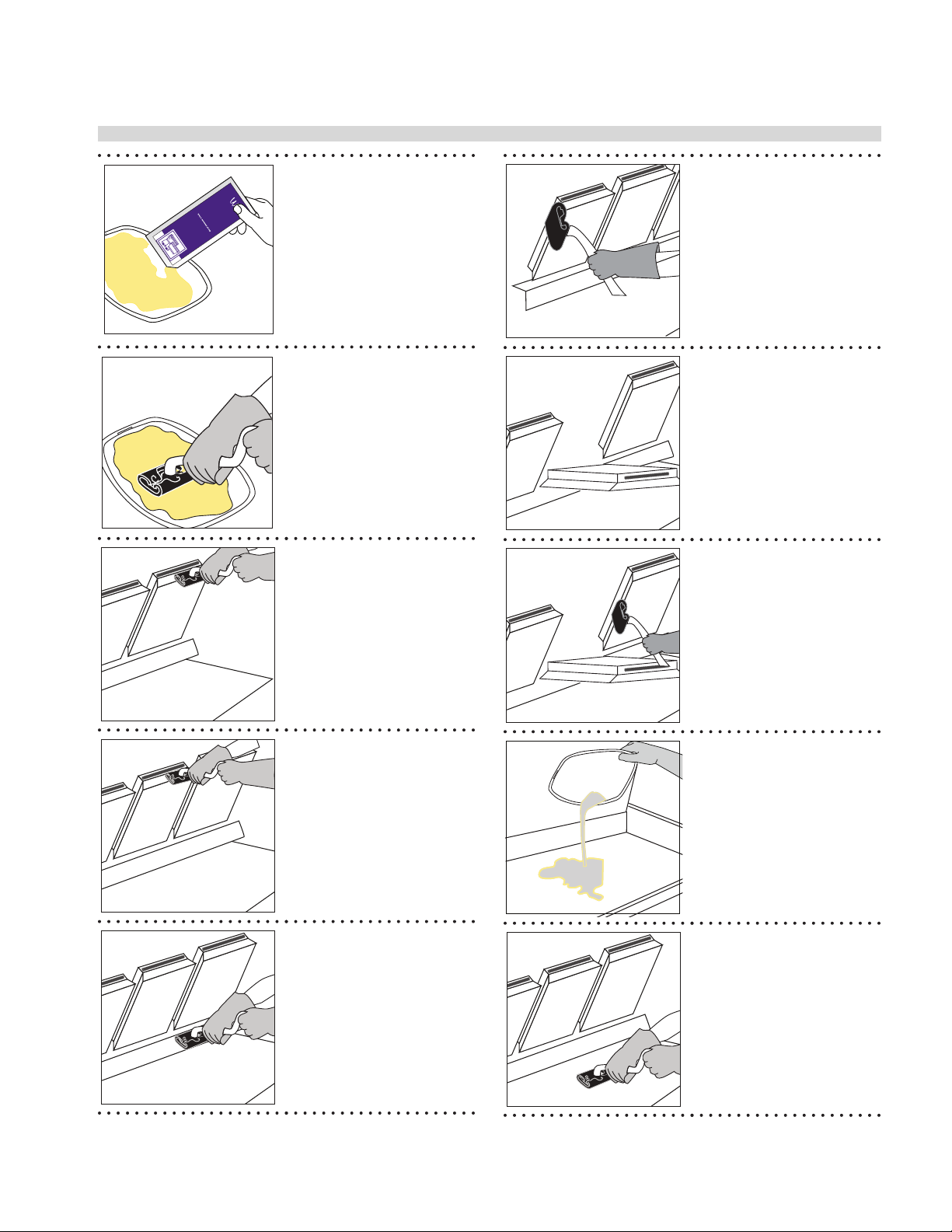
CLEANING & MAINTENANCE
McD
®
Hi-T emp Grill Cleaner
Nettoyant à chaud
pour grils
Limpiador de parrilla s
de alta temperatur a
CAUTION: May cause eye and skin
irritation. See precautionary and
KEEP OUT OF REACH OF CHILDREN
CUIDADO: Puede causar irritación
de los ojos y la piel. Véanse
las precauciones y los primeros
auxilios al reverso.
MANTENGASE FUERA DEL
ALCANCE DE LOS NIÑOS
AVIS : Peut irriter les yeux et la peau.
Voir précautions et premiers
soins au verso.
CONSERVER HORS DE LA
PORTÉE DES ENFANTS
®
3.6 oz (106 ml)
McD
® Hi-Temp
Grill Cleaner
KAY® Grill Cleaning Pad Holder
®
Grill Cleaning Pad
& KAY
Heat-Resistant Gloves Clean, Sanitizer-Soaked
Grill Cloths
Lid
Grill Squeegee
Grill Scraper
• Select Clean Mode.
Once Clean Mode has
AUTO
AM
MAN
PM
P
been reached turn
grill OFF.
• After turning grill OFF,
platens can be controlled
• If splash guards are
installed, detach
and take to the
3-compartment sink to
be washed and rinsed;
set aside.
by pressing green button
• Scrape the lower grill
surface with the grill
scraper.
• Wipe the Release
Material® sheets with a
clean, sanitizer-soaked
grill cloth.
• Use grill squeegee to
push residual grease into
trough.
• Take grill scraper to the
5
3-compartment sink to
be washed and rinsed.
• Remove the locking
clips, bars, and release
sheets.
• Take the clips and bars to
the 3-compartment sink
to be washed and rinsed;
• Empty and replace the
grease troughs.
set aside.
• Set release sheets aside
on a at surface.
6
PART #4521777 (03/30/10)Page 6
Page 7
GARLAND CLAMSHELL GRILLS WITH PRODUCT RECOGNITION INSTALLATION/OPERATION MANUAL
9
10
11
12
13
14
16
CLEANING & MAINTENANCE continued
LA
ANTS
la peau.
3.6 oz (106 ml)
PORTÉE DES ENF
soins au verso.
DE LOS NIÑOS
CONSERVER HORS DE
Peut irriter les yeux et
Voir précautions et premiers
ALCANCE
auxilios al reverso.
MANTENGASE FUERA DEL
AVIS :
Puede causar irritación
las precauciones y los primeros
de los ojos y la piel. Véanse
CUIDADO:
KEEP OUT OF REACH OF CHILDREN
irritation. See precautionary and
®
CAUTION: May cause eye and skin
pour grils
de alta temperatur a
McD
Limpiador de parrilla s
Nettoyant à chaud
Hi-Temp Grill Cleaner
• Open one packet of McD
Hi-Temp Grill Cleaner
and empty the contents
into a lid or stainless
steel pan.
• Put on the heat-resistant
• Apply the grill cleaner to
outer edges of right and
left platens.
• DO NOT SCRUB
gloves.
7
• Dip the KAY Grill
Cleaning Pad Holder into
the grill cleaner.
• Press green button to
lower center platen.
8
• Apply McD Hi-Temp
Grill Cleaner to front
side of platens starting
from right platen to left
platen.
• DO NOT SCRUB
• Apply grill cleaner to
inner edges of the right
and left platens.
• DO NOT SCRUB
• Press green button to
raise right platen.
PART #4521777 (03/30/10)
• Apply the grill cleaner to
platen surfaces starting
from right platen to left
platen.
• DO NOT SCRUB
• Apply the grill cleaner
to back side of platens
from right platen to left
platen.
• DO NOT SCRUB
• Pour remaining McD HiTemp Grill Cleaner over
bottom grill surface.
15
• Spread the cleaner over
the entire lower grill
surface from front to
back using even strokes.
• DO NOT SCRUB
Page 7
Page 8
INSTALLATION/OPERATION MANUAL GARLAND CLAMSHELL GRILLS WITH PRODUCT RECOGNITION
17
18
19
20
21
22
23
24
25
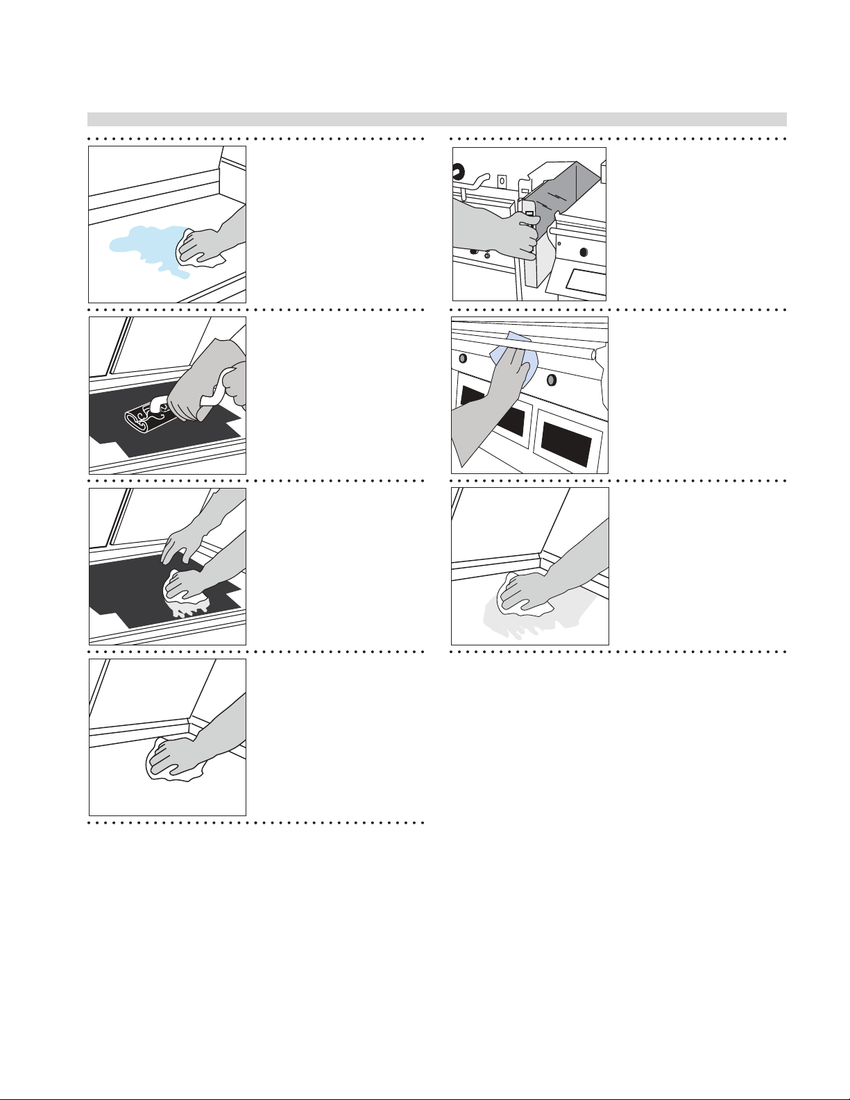
CLEANING & MAINTENANCE continued
• Scrub front side of
platens from right platen
to left platen with KAY
Grill Cleaning Pad Holder
and Pad.
• Scrub at grill surfaces
starting from right platen
to left platen.
• Scrub back side of
platens from right platen
to left platen.
• Scrub inner edges of the
right and left platens.
• Press green button to
raise the center platen.
• Scrub lower grill surface.
• Rinse front, side and
back of platen surfaces
with a clean, sanitizersoaked grill cloth,
starting from right to left
platens.
• Scrub outer edges of
right and left platens.
• Press green button to
lower center platen.
• Press the green button
to lower right platen,
rinse inner edges of both
platens; then, raise.
• Wipe back of lower grill
with a clean, sanitizersoaked grill cloth.
26
PART #4521777 (03/30/10)Page 8
Page 9
GARLAND CLAMSHELL GRILLS WITH PRODUCT RECOGNITION INSTALLATION/OPERATION MANUAL
32
33
29
30
CLEANING & MAINTENANCE continued
• Pour a small amount of
lukewarm water on a
clean, sanitizer-soaked
grill cloth over the
bottom grill surface and
wipe o residue.
• Empty, wash, rinse,
and replace the grease
troughs.
27
28
• Place upper platen
Release Material sheets
at on grill surface.
• Gently clean both sides
of the Release Material
sheets with the KAY Grill
Cleaning Pad Holder.
• Rinse both sides of the
Release Materialsheets
with a clean, sanitizersoaked grill cloth.
• Reinstall upper Release
Material sheets; secure in
place with bars and clips.
31
• Wipe remaining grill
surfaces with a clean,
sanitizer-soakedgrill
cloth.
• Apply a thin coat of fresh
shortening to the lower
grill surface only.
PART #4521777 (03/30/10)
• Wipe lower grill with a
clean,sanitizer-soaked
grill cloth. Repeat until
no visible soil remains.
Page 9
Page 10
INSTALLATION/OPERATION MANUAL GARLAND CLAMSHELL GRILLS WITH PRODUCT RECOGNITION
SPECIFICATIONS
Dimensions:
Models MWE3W, MWG3W
.737
[19mm]
34.968
[888mm]
4.064
[103mm]
"COLD ZONE"
48°
24.000
[610mm]
(PLATE DEPTH)
5.475
[139mm]
SK07-587 (GAS)
19.001
[483mm]
7.111
[181mm]
7.110
[181mm]
4.895
[124mm]
36.000
[914mm]
(PLATE WIDTH)
38.000
[965mm]
[MWG3W ONLY]
30.714
[780mm]
BOTTOM CABLE
FLUE EXIT
1.146
[29mm]
22.835
[850mm]
2.993
[76mm]
9.335
[237mm]
ENTRANCE
1.598
[41mm]
24.084
[612mm]
28.771
[731mm]
1.516
[39mm]
26.679
[678mm]
10.730
[273mm]
3/4" NPT GAS INLET
[MWG3W ONLY]
.787
[20mm]
7.875 [200mm]
9.684
[246mm]
15.384
[391mm]
1.500
[38mm]
30.750
[781mm]
TO
33.000
[838mm]
(COOKING
HEIGHT)
6.106
[155mm]
13.123
[333mm]
BOTTOM CABLE
ENTRANCE
23.812
[605mm]
9.901
[251mm]
3/4" NPT GAS INLET
[MWG3W ONLY]
36.027
[915mm]
PART #4521777 (03/30/10)Page 10
Page 11
GARLAND CLAMSHELL GRILLS WITH PRODUCT RECOGNITION INSTALLATION/OPERATION MANUAL
SPECIFICATIONS
Dimensions:
Model MWE3S
21.65
[550mm]
PLATE DEPTH
5.475
32.60
[828mm]
[139mm]
36.00
[914mm]
PLATE WIDTH
38.00
[965mm]
30.714
[780mm]
2.993
[76mm]
9.335
[237mm]
BOTTOM CABLE
ENTRANCE
1.598
[41mm]
24.084
[612mm]
26.42
[671mm]
1.516
[39mm]
24.33
[618mm]
1.70 [43mm]
“COLD ZONE”
48°
.787
[20mm]
7.875 [200mm]
9.684 [246mm]
1.50
[38mm]
15.384
[391mm]
COOKING HEIGHT
BOTTOM CABLE
30.75 [781mm]
TO
33.00 [838mm]
6.106
[155mm]
ENTRANCE
13.123
[333mm]
23.812
[605mm]
36.027
[915mm]
PART #4521777 (03/30/10)
Page 11
Page 12

INSTALLATION/OPERATION MANUAL GARLAND CLAMSHELL GRILLS WITH PRODUCT RECOGNITION
SPECIFICATIONS
Input Specications, ELECTRIC FULL SIZE Grills, MWE3W, United States:
SUPPLY
REQUIRED
INPUT 1 7.65 21.3 21.3 21.3 20.1 20.1 20.1 18.4 18.4 18.4
INPUT 2 15.30 42.6 42.6 42.6 40.2 40.2 40.2 36.8 36.8 36.8
TOTAL
KW
LOAD
208V 220V 240V
L1 L2 L3 L1 L2 L3 L1 L2 L3
NOMINAL AMPS PER LINE
Input Specications, ELECTRIC FULL SIZE Grills, MWE3W, Western Canada:
SUPPLY
REQUIRED
INPUT 1 22.95 63.9 63.9 63.9 55.2 55.2 55.2
TOTAL
KW
LOAD
NOMINAL AMPS PER LINE
208V 240V
L1 L2 L3 L1 L2 L3
Input Specications, Electric Grills, CE Approved Models MWE3W-CE, MWE3S-CE:
SUPPLY
3N~ 400V
50Hz
TOTAL kW
LOAD
22.7
LOADING: (kW/PHASE) NOMINAL AMPS PER LINE
230V / 400V 230V / 400V
L1/L2 L1/L3 L2/L3 L1 L2 L3
7.60 7.60 7.60 33.0 33.0 33.0 Type 748
MENNEKES
PLUG &
RECEPTACLE
MAY BE
REQUIRED
Input Specications, Electric Grills, Export, Non-CE Models MWE3W, MWE3S:
LOADING: (kW/PHASE)
SUPPLY
220V 50Hz 22.7 7.60 7.60 7.60 34.5 34.5 34.5
240V 50Hz 22.7 7.60 7.60 7.60 31.6 31.6 31.6
TOTAL kW
LOAD
L1/L2 L1/L3 L2/L3 L1 L2 L3
230V / 400V 230V / 400V
NOMINAL AMPS PER LINE
MENNEKES
PLUG &
RECEPTACLE
MAY BE
REQUIRED
Type 748
PART #4521777 (03/30/10)Page 12
Page 13

GARLAND CLAMSHELL GRILLS WITH PRODUCT RECOGNITION INSTALLATION/OPERATION MANUAL
SPECIFICATIONS
Input Specications, GAS Grills, North America:
SUPPLY
REQUIRED
TOTAL
kW
LOAD
LOADING: (kW/
PHASE)
208V / 220V / 240V 208V / 60Hz 220V / 60Hz 240V / 60Hz
L1/L2 L1/L3 L2/L3 L1 L2 L3 L1 L2 L3 L1 L2 L3
NOMINAL AMPS PER LINE
INPUT 1 10.0 3.25 3.25 3.25 28.0 28.0 28.0 26.3 26.3 26.3 24.0 24.0 24.0
GAS INPUT
GAS
MAX INPUT
NET PER
BURNER
BTU/H
TOTAL INPUT
RATING
BTU/H
INJECTOR
SIZE
AIR SHUTTER
SETTING
MM
SUPPLY
PRESSURE
IN W.C.
BURNER
MANIFOLD
PRESSURE
IN W.C.
NATURAL GAS 32,000 96,000 #35 4.8 3.5 3.5
PROPANE 32,000 96,000 #43 4.8 3.5 3.5
Input Specications, GAS Grills, CE Approved Model MWG3W-CE:
3N~ 400V
50Hz
LOADING: (kW/PHASE) NOMINAL AMPS PER LINE
TOTAL kW
LOAD
L1/L2 L1/L3 L2/L3 L1 L2 L3
10.0 3.25 3.25 3.25 14.1 14.1 14.1 Type 748
MENNEKES
PLUG &
RECEPTACLE
MAY BE
REQUIRED
GAS INPUT
GAS GROUP
MAX INPUT
NET PER
BURNER kW
TOTAL
INPUT
RATING
kW
INJECTOR
SIZE
AIR
SHUTTER
SETTING
mm
SUPPLY
PRESSURE
mbar
BURNER
PRESSURE
mbar
VOLUMETRIC
G20 NG 8.9 26.7 2.79mm (#35) 4.8 20/25 8.7 0.940 m3/h
G25 NG 2.79mm (#35) 4.8 20 8.7
G31 LPG 8.9 26.7 2.26mm (#43) 4.8 37/50 8.7 0.69 kg/h
NET HEATING VALUE BY GAS GROUP
G20 G25 G31
34.02 MJ/m3; 0.555 SG 29.25 MJ/m3; 0.613 SG 88.0 MJ/m3 (46.34 MJ/kg); 1.55 SG
GAS CATEGORIES
CATEGORY DESTINATION COUNTRIES SUPPLY PRESSURE (mbar)
I
2H
I
2E
I
2L
I
2ER
I
3P
I
3P
I
3P
AT, CH, CZ, DK, ES, FI, GB, IE, IS, IT, NO, PT, SE 20.0
DE, LU 20.0
NL 25.0
FR 20.0 / 25.0
NL 30.0
BE, CH, CZ, ES, FR, GB, GR, IE, LU 37.0
BE, CH, DE, CZ, ES, FR, NL 50.0
PART #4521777 (03/30/10)
GAS RATE
Page 13
Page 14

INSTALLATION/OPERATION MANUAL GARLAND CLAMSHELL GRILLS WITH PRODUCT RECOGNITION
INSTALLATION & STARTUP
Installation Store Responsibilities:
• Ensure grill has been installed by a competent trained
installation person.
• Ensure store readiness of utilities, product & personnel.
• Contacting your local Garland Factory Authorized
Service Center for a startup date.
• Participate in the startup to ensure a successful startup
and familiarity with the grill.
• Conduct training with your crew personnel to ensure
maximum utilization of the grill.
Once the installation is complete as per the procedures
below, a factory authorized service company MUST startup
the grill according to Garland Commercial Industries
startup standards.
A startup DOES NOT include:
1. Uncrating the unit
2. Placing the unit in its position under the exhaust hood.
5. Verify operation of platens, if applicable, and timer
functions.
6. Ensure time out alarm is functional and platens raise (if
applicable)
7. Set proper gas and verify with beef integrity check that
two consecutive runs yield the approved beef integrity
results as per McDonalds standards.
8. Conduct brief training to store manager on the
operation of the grill.
Items included with the purchase of your
new grill from Manufacturer:
1. One (1) grill
2. One (1) gas hose (for gas grills only)
3. One (1) box containing:
a. Six (6) release material sheets
b. Three (3) release material clips
c. Three (3) release material rear rods.
3. Leveling the grill on the oor under the exhaust hood.
4. Attaching the supply cord(s) unless supplied by the
factory.
5. Making adjustments to the ventilation system.
6. Sheet metal work required due to improper exhaust
hood application.
7. Adjusting the grill to achieve beef integrity that
deviates from the McDonalds standard.
A start-up DOES include:
1. Verication of supply voltage and, if applicable gas
supply.
2. Leak test and gas pressure check on gas grills.
3. Electrical safety check.
4. Verify operation of grill by allowing unit to attain set
temperature.
4. One (1) box containing four (4) casters.
Items NOT INCLUDED from the manufacturer
and should be purchased from the KES:
1. Any electrical cords needed for application.
2. Any ue box needed for application.
3. Any grease traps or grease rails needed for application.
THE FOLLOWING INSTALLATION
PROCEDURE CAN BE PERFORMED BY A:
• FACTORY AUTHORIZED SERVICE CENTER
• AN APPROVED INSTALLATION PERSON APPROVED BY
PURCHASER OF GRILL
• LICENSED INSTALLER CONTRACTED BY KES (KITCHEN
EQUIPMENT SUPPLIER)
WARNING: PLEASE READ INSTALLATION INSTRUCTIONS CAREFULLY. FAILURE TO PERFORM
THESE STEPS CAN RESULT IN EQUIPMENT FAILURE, DAMAGE AND / OR VOID OF WARRANTY.
PART #4521777 (03/30/10)Page 14
Page 15

GARLAND CLAMSHELL GRILLS WITH PRODUCT RECOGNITION INSTALLATION/OPERATION MANUAL
RECOMMENDED PLUG
MWG3W = 1X NEMA 15-30
MWE3W = 2X NEMA 15-50
MWG3W HAS ONE ELECTRICAL CORD.
MWE3W HAS TWO ELECTRICAL CORDS.
Electrical Cable Hookup
DUAL POWER SUPPLY CONNECTION
USA & some other
POWER CORDS & PLUGS
ARE NOT SUPPLIED
BY THE MANUFACTURER
INPUT 1
INPUT 2
INSTALLATION & STARTUP (continued)
1. Uncrate unit from crating material
CAUTION: Prior to installation, check the electrical supply
to ensure input voltage and phase match the equipment
voltage rating and phase.
NOTE: ENSURE THAT PLATENS ARE STRAPPED DOWN
SECURELY THROUGH STEP 3 TO PREVENT PLATENS
FROM RAISING. SEVERE DAMAGE MAY OCCUR.
WARNING: Electrical appliances must be electrically
grounded in accordance with local codes or in the absence
of local codes, with national electric code ANSI/NFPA latest version.
All electric connections must be made by a qualied,
properly equipped technician.
Electrical Cable Hookup
DUAL POWER SUPPLY CONNECTION
SINGLE POWER SUPPLY CONNECTION
USA & some other
MWG3W HAS ONE ELECTRICAL CORD.
MWE3W HAS TWO ELECTRICAL CORDS.
RECOMMENDED PLUG
MWG3W = 1X NEMA 15-30
MWE3W = 2X NEMA 15-50
POWER CORDS & PLUGS
ARE NOT SUPPLIED
BY THE MANUFACTURER
Electrical Cable Hookup
where required by local regulations
INPUT 1
INPUT 2
2. Tip unit over on its back. Install caster channels and
casters as shown. WARNING: It is recommended
that the rear casters are screwed in all the way before
tipping.
3. Carefully rotate grill back on its casters. Now you may
cut and remove the platen securing straps.
4. Remove back body side and Install power cords per
your country / area’s specications.
RECOMMENDED PLUG
MWG3W = 1X NEMA 15-30
MWE3W = INSTALL LINE SIDE
MIN. #10AWG “JUMPERS”
INPUT 1 to INPUT 2
1X NEMA 15-60
POWER CORDS & PLUGS
ARE NOT SUPPLIED
BY THE MANUFACTURER
INPUT 1
Hood-Interlock & Control Power Supply; where applicable
1 x 20AMP NEMA 21-20
POWER CORDS
ARE NOT SUPPLIED
BY THE
MANUFACTURER
EEL1 L1 L1 L1
L1 L1 L1 L1
WhWht
Wht
Wht Wht Wht
t Wht Wht
INPUT 2
Ora Red
Ora Red Blk
Blk
PART #4521777 (03/30/10)
Page 15
Page 16

INSTALLATION/OPERATION MANUAL GARLAND CLAMSHELL GRILLS WITH PRODUCT RECOGNITION
ATTACH HANGER #4527008 TO BASE IN LOCATION SHOWN
INSTALLATION & STARTUP (continued)
5. GAS GRILL ONLY, (for electric grills, skip to step 7):
Install the included quick-disconnect gas hose to the
inlet tting on the underside of the grill by threading
a 3/4” NPT nipple into the elbow, then install the brass
male quick-disconnect coupler included with the hose.
Connect the hose and ensure the sleeve snaps fully
forward against the retaining ring.
FLEXIBLE GAS HOSE
GAS
FLOW
TO GAS
SUPPLY
FACTORY
INSTALLED
GAS INLET
UNDERNEATH GRILL
MALE COUPLER
[INSTALL FIRST]
With the manual shut-o valve closed, install the other
end of the hose to the gas supply.
6. Install Optional Front Gas connection (If available).
15.58
ATTACH FLEX GAS LINE TO ELBOW
9.94
6.08
50°
WITH #10-24 SELF TAPPING SCREWS
INSTALL 3/4 NIPPLE THROUGH HANGER AND INTO
EXISTING ELBOW
7. Install grease bucket rails as shown below:
GREASE BUCKETS & RAILS
ARE NOT SUPPLIED
BY THE MANUFACTURER
8. Install ue box to back of grill.
FLUE BOX IS
NOT SUPPLIED BY
THE MANUFACTURER
ROTATE EXISTING ELBOW TO ANGLE SHOWN
a. Isolate grill from any power source by unplugging
all electrical connections.
b. Rotate existing elbow 50° as shown in the diagram
to the left.
c. Attach hanger PN 4527008 as shown with 10-24 self
tapping screws.
d. Install 3/4 nipple through hanger and into existing
already rotated elbow.
e. Install 3/4 elbow tting to 3/4 nipple.
f. Attach gas hose to extended gas line.
9. Roll grill under exhaust hood. Grill must be level front
to back, side to side and diagonally. Adjust casters
accordingly to obtain nal level.
PART #4521777 (03/30/10)Page 16
Page 17

GARLAND CLAMSHELL GRILLS WITH PRODUCT RECOGNITION INSTALLATION/OPERATION MANUAL
INSTALLATION & STARTUP (continued)
Exhaust hood Type & Platen Height
With the platens in the raised position, measure the
height from the front edge of the platen to the grill
surface. Determine which type of exhaust hood the
store has and check for exhaust hood type/platen
height compatibility according to the table below:
Exhaust hood
TYPE
Universal 18 1⁄2” (470mm)
92 Series 17” (432mm)
GSC 18 1⁄2” (470mm)
If the platen height is incompatible with the exhaust
hood type, platen height must be adjusted by an
authorized service agent.
CORRECT PLATEN HEIGHT
PLATEN
HEIGHT
GRILL
PLATE
PART #4521777 (03/30/10)
Page 17
Page 18

INSTALLATION/OPERATION MANUAL GARLAND CLAMSHELL GRILLS WITH PRODUCT RECOGNITION
□
□
□
□
□
□
□
□
□
□
□
□
□
INSTALLATION & STARTUP (continued)
Startup Procedure
This Garland 3-platen grill comes
with a factory startup at no additional
charge. A startup is required to
take place BEFORE the unit is put
into operation. It is the end-user
responsibility to schedule the startup
with their local Factory Authorized
Service Agent, or notify Garland
Commercial Industries at 1-800-4468367 should you need assistance
scheduling.
A factory startup is a comprehensive
grill check in which a factory certied
technician will document all nal
settings programmed in the controller
once various other performance
checks are complete. The estimated
time to complete a startup is
approximately 2.5 – 3.5 hours. Please
keep in mind this estimated time
when scheduling the startup. After
hours or overtime is not covered under
warranty and will be billed at a charge
which is the dierence between the
Garland Reimbursement rate and the
Factory Authorized Service Centers
overtime charges.
A factory startup is necessary to
start the warranty period. The
Authorized Service Center is required
to complete the paperwork during
the startup process, and send it to
Garland Commercial Industries for
reimbursement. At the time of receipt,
Garland will start the warranty period
which will conclude at the end of 2
years. You may contact your Kitchen
Equipment Supplier or dial 1-866-7351955 for more details regarding an
optional 3rd year extended warranty
plan.
All aspects of the Starup procedure must be documented using the Garlandissued form, part #4521780:
GARLAND CLAMSHELL GRILL START – UP FORM
ELECTRIC OR COMBINATION GAS / ELECTRIC
(FOR USE IN MODEL MWE3W/MWG3W & MWE2W/MWG2W Series grills ONLY)
McDonald’s ____________ Certification ID # _________ Store # ___ __________ Start-up Date ________________________
Address _______________________________ City ________ _________________ Model # □MWE3W | □MWG3W | □MWE2W | □MWG2W
Circle One
State / Province ____________________________ Zip Code ____ _____________ Serial # _____________________________
□ United States □ Canada □ International (List Country) __________________ Telephone # _________________________
Actual Gas Type ____________
Matches Rating Plate? YES NO
1. Ensure grill is installed in the proper type of gas exhaust hood with the proper air draw.
2. Ensure flu restrictors are fully opened or removed. Flue Box Supplied by KES
Flu Restrictors located inside exhaust hood
3. Ensure bottom plate is leveled side to side / front to back / diagonally, in location, under hood. Adjust casters to attain level.
4. REMOVE GRILL FROM UNDER THE HOOD. Turn Power Switch ON, controller displays are active, Controller displays “OFF”.
All platen raises automatically?
5. Lower and raise Upper Platen and insure movement is smooth and continuous. Grease shafts accordingly with a FOOD GRADE
LUBRICANT.
6. If upper platen elevation requires lowered to allow for clearance of hood, lower upper limit switch. Refer to Operations &
Installation manual for platen heights.
7. Press the POWER ON button. Controller displays “PREHEAT - AM”, platen lowers. Heat indicator lights are AMBER?
8. Press the AM / PM key. This will allow the unit to heat to: Platen-425˚F(217˚C), Grill-350˚F(177˚C).
9. Grill enters SOAK mode (15:00 timer), counts down and upper platen auto calibrates at temperatures: Platen-425˚F(217˚C), Grill350˚F(177˚C)
10. Close valve handle and verify the unit tries to ignite four (4) times. Unit locked out to Ignition Failure?
11. GAS PRESSURE CHECKS (if applicable):
Rated Incoming Pressure Natural Gas 6 – 14 Inches W.C. Actual Incoming __________________
Propane / Butane Gas 11 – 14 Inches W.C. Actual Incoming __________________
Rated Burner Pressure Natural Gas 3.5 Inches W.C. Actual Left ________ Center ________ Right _________
Propane / Butane Gas 3.5 Inches W.C. Actual Left ________ Center ________ Right _________
12. Check micro amp reading to ensure operating micro amps ARE NO LESS THAN .8. Micro Amp reading should be between .9 –
1.2.
13. Upon Completion of auto calibration, platen raised automatically, and display reads “READY”
If upon completion of auto calibration process, upper platen does not raise, indicate message on controller. Check platen level and adjust
reed switches. Cycle power and retry.
14. Select menu item “10:1 – CLAM”. Verify set temperature is reached and LED lights turn GREEN.
15. Initiate cook cycle by pushing the GREEN PUSHBUTTON. Platen lowers, and timing cycle begins.
16. Ensure the stores pyrometer is accurate and calibrated using the ice bath method.
17. Perform PROBE CALIBRATION.
18. Perform Platen Zeroing procedure & Reed Switch Calibration in “LEVEL / REED SW” mode.
19. Platen performed Auto Calibration upon completion of reed switch calibration?
20. Assist or obtain assistance with store personnel for Beef Integrity Testing, testing product 10:1 and 4:1 until desired internal
product temperatures are met.
21. Record cook times, gap settings, and any gap calibrations used to obtain beef integrity.
22. Record Calibration numbers below:
Problems / Special Circumstances / Damage:
__________________________________________________________________________________________________________________________________
__________________________________________________________________________________________________________________________________
Name: __________________________________________________ Name: __________________________________________________
Service Agency: __________________________________________ Are you satisfied with the start-up procedure that has been performed?
Sub Agent: (If Applicable) __________________________________
Are you a factory certified technician? YES / NO
Date of Certification / /
Rev 3 P/N 4521780 W(091609)
Located on Certification Sticker MM / DD / YY
Gas Type E lectric / 3-phase Record Amps Per Line Each Contactor
NOTE: CENTER PLATEN should not be checked if MWE2W / MWG2W
Product Cook Times
(MWE3W & MWG3W | MWE2W & MWG2W)
LEFT
10:1 LEFT
4:1 CENTER
ANGUS RIGHT
2 PLATEN PRC Grills
ONLY
LEFT
RIGHT
Submitted by: Accepted by:
White Copy – Factory Ye llow Copy – Service Agency Pick Copy – Customer
Actual Input _______________
□ 208 VAC □ 380 VAC
□ 220 VAC □ 400 VAC
□ 230 VAC □ 415 VAC
□ 240 VAC
INSPECTION / OPERATIONAL CHECK
Calibration numbers (from CALIBRATION MENU)
CENTER
If Applicable
Calibration numbers (from CALIBRATION MENU)
Front LT
Back LT
Cal
Cal
Back
RIGHT
MWE2W & MWG2W ONLY
Front RT
Back RT
Cal
Please indicate any comments
__________________________________________________________________
______________________________________________
MWE3W & MWG3W ONLY
Reed Cal
Front LT
Cal
Detect
Line 1
Line 2
Line 3
Front
Reed Cal
Back LT
Detect
Center
Left
If Applicable)
□ OK
□ OK
OK
□ OK
L
□ OK | C □ OK | R □ OK
L
□ OK | C □ OK | R □ OK
L
□ OK | C □ OK | R □ OK
OK | C □OK | R □OK
L
OK | C □OK | R □OK
L
OK | C □OK | R □OK
L
L
OK | C □OK | R □OK
L / □ C / □ R
OK -
Check Platen Level - □ L / □ C / □ R
Check Reed Switch - □ L / □ C / □ R
L
OK | C □OK | R □OK
OK | C □OK | R □OK
L
OK
OK | C □OK | R □OK
L
OK | C □OK | R □OK
L
OK | C □OK | R □OK
L
□ OK | C □ OK | R □ OK
L
L
OK | C □OK | R □OK
Back
Front
Zero Cal
Zero Cal
Front RT
Back RT
Detect
Detect
Right
PART #4521777 (03/30/10)Page 18
Page 19

GARLAND CLAMSHELL GRILLS WITH PRODUCT RECOGNITION INSTALLATION/OPERATION MANUAL
INSTALLATION OF WRAP AROUND RELEASE MATERIAL
MOUNTING BRACKETS
CAUTION: UPPER PLATEN IS EXTREMELY HOT. WARNING: ISOLATE POWER SOURCE TO PREVENT ELECTRICAL SHOCK.
1. Ensure Electrical Power is unplugged before
proceeding to next step.
2. Loosen 2 screws from each side of the platen lid.
3. Position side bracket assemblies over screws and insert
into place.
4. Retighten four (4) screws on the platen lid.
TEFLON
MOUNTING
Part
Number
4526334 Release Material
4527294 Release Material
Description Qty Per Full Size
(3P) Grill
6 Grill, 2 Platen
sheet Bracket, Side
(3 Platen Grill)
15 Grill, 5 Platen
sheet Clip w/ Flange
SIDE
BKT
INSTALLATION OF SPLASH SHIELD
PLATEN ARM
ARM CARRIAGE BLOCK
ARM CARRIAGE BLOCK PIN
SURFACE OF
GRILL PLATE
NOTE: SOME COMPONENTS OMITTED FOR CLARITY
SPLASH SHIELD TAB
SPLASH SHIELD
SPLASH SHIELD TABS
UP AND OVER
ARM CARRIAGE PINS
IN THIS DIRECTION
NOTE: SOME COMPONENTS OMITTED FOR CLARITY
PART #4521777 (03/30/10)
Page 19
Page 20

INSTALLATION/OPERATION MANUAL GARLAND CLAMSHELL GRILLS WITH PRODUCT RECOGNITION
INSTALLATION OF RELEASE MATERIAL
1. Slide release material rod through hemmed end of the
release material sheet.
HEMMED
2. Hook release
material rod on
brackets located
MATERIAL
ROD
LOOP
at the rear of the
upper platen.
3. Holding the
bottom of the
release material
sheet in place,
“Teflon Sheet” available from your DC
Saint Gobain: DC WRIN # 02180-003
Taconic: DC WRIN # 02180-000
RELEASE
MATERIAL
gently pull the
sheet toward
the front of the platen.
NOTE: Make sure release material ts smoothly over upper
platen.
4. Place one (1) locking clip over release material sheet in
front and press into place over release material bar.
5. Gently pull the
release material
sheet ap over
the left side of the
platen and secure in
place with two (2)
locking clips.
6. Repeat step 5 with
UPPER
PLATEN
(SIDE VIEW)
MATERIAL
MATERIAL ROD
RELEASE
HOLDER
MATERIAL
ROD
the right side.
NOTE: Failure to
install the correct
number of clips on
the upper platen
will cause the
release material to
be loose, and wear
quickly. Ensure the
correct placement
of ALL clips to
prevent premature
wear and/or poor
product quality.
5. Check
alignment
and rightness
of release
material
against upper
platen.
RELEASE
MATERIAL
FLAPS
RELEASE
MATERIAL
RELEASE
MATERIAL
CLIPS
FLAPS
INSTALLATION OF VAPOR SHIELD
TEFLON
FRONT
BAR
VAPOR SHIELD
UP & OVER
TEFLON
FRONT BAR
PART #4521777 (03/30/10)Page 20
Page 21

GARLAND CLAMSHELL GRILLS WITH PRODUCT RECOGNITION INSTALLATION/OPERATION MANUAL
AVAILABLE ACCESSORIES
Splash Shield
Item 4523492
Vapor Shield Complete (2 shown)
Item CK4525215
Teon Wraparound kit (1 platen only)
CK4528080-1 - includes (Shown)
(3) Teon Sheet (Wraparound) - 4527643
(5) Clips - 4527294
(1) Teon Rear Bar - 4521355
Teon Wraparound kit (3 platens)
CK4528080-3 - includes (Not Shown):
(9) Teon Sheet (Wraparound) - 4527643
(15) Clips - 4527294
(3) Teon Rear Bar - 4521355
Teon Wraparound kit (1 platen only)
w/ Brackets
CK4528085-1 - includes: (Shown)
(3) Teon Sheet (Wraparound) - 4527643
(5) Clips - 4527294
(1) Teon Rear Bar - 4521355
(2) Wraparound side mount bkts - 4526334
PART #4521777 (03/30/10)
Teon Wraparound kit (3 platens)
CK4528085-3 - includes: (Not Shown)
(9) Teon Sheet (Wraparound) - 4527643
(15) Clips - 4527294
(3) Teon Rear Bar - 4521355
(6) Wraparound side mount bkts - 4526334
Page 21
Page 22

INSTALLATION/OPERATION MANUAL GARLAND CLAMSHELL GRILLS WITH PRODUCT RECOGNITION
AVAILABLE ACCESSORIES (continued)
NEMA# 51-50P
3Phase 4Wire 50 AMP Power Cord (Electric Grill ONLY)
(No Garland P/N) - *** Not supplied by Garland
Quick-Disconnect Gas Hose
Item 1591506
NEMA# L21-20P
Interlock Cord - 5Wire
(No Garland P/N) - *** Not supplied by Garland
NEMA# L15-30P
3Phase 4Wire 30 AMP Power Cord (Electric Grill ONLY)
(No Garland P/N) - *** Not supplied by Garland
PART #4521777 (03/30/10)Page 22
Page 23

GARLAND CLAMSHELL GRILLS WITH PRODUCT RECOGNITION INSTALLATION/OPERATION MANUAL
DESCRIPTION OF GRILL CONTROL
Right Arrow Button – In any mode, scrolls
forward through a list
Left Arrow Button – In any mode, scrolls
backward through a list
Enter Button – In the normal operating
mode, this button is not active. In the
Power Button – PRESSING and HOLDING the
Power button for 2 seconds will either turn
the controller on or o.
AM/PM Button – In normal operating mode,
toggles between the AM menu library and
the PM menu library.
AUTO/MAN Button – In normal operating
mode, toggles between Automatic Product
Recognition and Manual Cooking.
Up Arrow Button – In any mode, increases
the value of the ashing cursor character in
the display
Programming Mode, used to lock in the
values shown on the display.
Program Button – In the normal
operating mode, pressing and holding the
PROGRAM button for 3 seconds enters the
Programming Mode.
Temp Button – In the normal operating
mode, displays the set temperature and the
actual temperature.
Speed Key – In the normal operating mode,
used to change cook time. Also used to enter
Probe Calibration Mode.
Down Arrow Button – In any mode,
decreases the value of the ashing cursor
character in the display
Standby Button – In the normal operating
mode, places the grill in Standby Mode.
POSSIBLE ERROR MESSAGES
GRILL PROBE ERROR – A grill probe circuit error for the Front, Middle, or Back zone has occurred.
PLATEN PROBE ERROR – An upper platen probe circuit error has occurred.
HEATER ERROR – Occurs when the controller does not detect a temperature rise in six (6) minutes.
HIGH TEMP – Occurs when the controller senses a temperature of 465˚ F (241˚ C).
CHECK REED SWITCH / USE FLAT COOK – One or more of the reed switches are out of adjustment. User will only be able
to cook FLAT menu items.
ERROR COMMS - A communications error has occured between the Motor Speed Control and the Main Control.
PLATEN NOT LEVEL – Occurs if the calibration dierence between the front and rear is greater than maximum allowance.
Product Recognition (Auto) and manual cooking is DISABLED. Flat Menu cooking is ONLY allowed.
CHECK PLATEN LEVEL – Occurs if the calibration dierence between the front and rear is greater than the minimum
allowance, but less than the maximum allowance. Product Recognition (Auto) is DISABLED. Perform
If CHECK PLATEN LEVEL is displayed, perform the following steps:
1. PRESS AND HOLD the and buttons for 3 seconds. The control will display “AUTO GAP FORCE”.
2. PRESS the button. “NO” will ash on the display. PRESS the button to change it to “YES.”
3. PRESS the button. The platen will immediately lower and reset its internal measurements. Upon completion,
the platen will rise. If the error message does not return continue operating normally, contact your local authorized
service agent.
PART #4521777 (03/30/10)
Page 23
Page 24

INSTALLATION/OPERATION MANUAL GARLAND CLAMSHELL GRILLS WITH PRODUCT RECOGNITION
OPERATING PROCEDURES
General Overview:
The PRC grill control will allow for 2 functions, both
described in detail in the following sections
The “Normal Operating Mode”, also known as the Cook
Mode is the mode used during normal cooking. In the
normal operating mode, the operator can start a cook
cycle, cancel a cook cycle, view actual temperatures, scroll
to another menu item, and enter the Programming Mode.
The “Programming Mode” is the mode in which the
operator can program the controller’s various settings. To
enter the programming mode, PRESS and HOLD
There are currently 3 methods of cooking that can be
utilized with the MWE3 Garland clamshell:
Standard Cooking – This is the cook method that utilizes a
single gap setting for each menu item. The timer will count
down according to the selected menu item.
Multi Stage Cooking – This method of cooking utilizes 2
dierent gap settings during the cook cycle. The timer will
count down according to the selected menu item.
Product Recognition – The product recognition method
of cooking uses the magnetic switches mounted on the
upper platen arm assembly to determine the product
being cooked. Using the PR feature, the operator simply
selects the button on the controller. This will allow
the controller to know what product group to select
from. When a cook cycle is initiated, the platen will come
down and recognize the product being cooked. The
cook timer will count down according to the time set for
the recognized item. For more information on product
Recognition, see the next section; “Product Recognition.”
To turn the grill on:
The Main Power Switch – Controls power to the grill
and must be turned ON to start operation. The controller
displays will be active. Upon successful power up checks,
the controllers will displays “OFF”.
AM Operation – Release Material sheets MUST be ON at
this time and the grill surface should be free and clear of
carbon.
Once the PRC displays “OFF” press . The PRC will go to
PREHEAT mode and default to AM preheat temperatures.
To preheat to PM temperatures, press and hold .
AM PREHEAT PM PREHEAT
375˚F (190˚C) Upper Platen 425˚F (218˚C) Upper Platen
275˚F (135˚C) Grill 350˚F (177˚C) Grill
Page 24
Upon reaching the AM or PM set temperature (whichever
is selected), the grill will stabilize in temperature for fteen
(15) minutes. Once this time has elapsed, the grill will
autocalibrate. Upon completion of autocalibration, the
upper platens will raise to there normal position, and the
PRC will display “READY”.
To Select a Menu item:
Scroll forward through the list of available menu items by
pressing repeatedly. Scroll backward through the list of
available menu items by pressing repeatedly.
Menu Item Library
The menu item library is loaded in the computer based
upon the setting programmed in [CONFIGURE]->[GRILL
REGION]. Each menu item consists of a function called
[DISPLAY ACTIVE]. The settings in this function (AM, PM,
AM/PM, No) determine what menu items are displayed
when the button is pressed.
Menu
Item #
1 10:1 - CLAM PM
2 4:1 - CLAM PM
3 STRIP BACON - CLAM AM/PM
4 SAUSAGE CLAM FZN AM
5 MCRIB - CLAM NO
6 STEAK - CLAM AM/PM
7 GRILLED CHICKEN - FLAT PM
8 FOLDED EGGS FLAT AM
9 ROUND EGGS - FLAT AM
10 CHICKEN FLAT BRD - FLAT NO
11 10:1 FLAT NO
12 4:1 - FLAT NO
13 MCRIB - FLAT NO
14 SAUSAGE FLAT FZN NO
15 HOTCAKES - FLAT NO
16 OPT MENU 1 - CLAM NO
17 OPT MENU 2 - CLAM NO
18 ANGUS 3:1 CLAM NO
19 MUSHROOMS CLAM NO
20 OPT MENU 5 - CLAM NO
21 OPT MENU 6 - CLAM NO
22 OPT MENU 7 - CLAM NO
23 OPT MENU 1 - FLAT NO
24 OPT MENU 2 - FLAT NO
25 OPT MENU 3 - FLAT NO
26 OPT MENU 4 - FLAT NO
Menu Item
Display Active –
Default
Page 25

GARLAND CLAMSHELL GRILLS WITH PRODUCT RECOGNITION INSTALLATION/OPERATION MANUAL
OPERATING PROCEDURES (continued)
Indicator Lights
The LED lights on the main control indicate the
temperature status of each zone.
Electric grills have (4) zones per section , TOP, (platen),
BACK GRILL, MIDDLE GRILL, and FRONT GRILL.
Gas grills have (2) zones per section , TOP, (platen),
and GRILL.
RED – The zone(s) is “TOO HOT” (more than 79˚F/43˚C over
set temperature) OR a heat zone failure has occurred.
AMBER – The zone(s) is calling for heat.
GREEN – The zone(s) is at or above set temperature, but
below 79˚F/43˚C over set temperature.
Standby Mode
To enter the standby mode:
1. Press the button. The upper platen will lower, and
the grill will maintain a set temperature of Upper platen
- 425˚ F (218˚C), Grill Surface - 350˚ F (177˚C).
To Exit the standby Mode:
1. Press the GREEN PUSHBUTTON. The upper platen
will raise.
To display the current temperatures:
1. Press the button and repeat for each zone to be
displayed:
1st key press – Front Set Point
2nd key press – Front Actual
3rd key press – Mid Set Point
4th key press – Mid Actual
5th key press – Back Set Point
6th key press – Back Actual
7th key press – Platen Set Point
8th key press – Platen Actual
load product on the grill.
5. Press the GREEN pushbutton to initiate a cook cycle.
6. Alarm will sound when the cook cycle is complete.
7. Remove product and clean grill to prepare for the next
cook cycle.
Lunch In Manual mode
Note: Switching from breakfast to lunch menu items will
take approximately 10 minutes to heat to the appropriate
temperatures.
1. Select PM mode. Press and hold the button.
2. Select Manual mode. Press and hold the button.
3. Select a product from the PM product library using the
or arrow buttons.
4. Following the below lay pattern, load product on the
grill.
5. Press the GREEN pushbutton to initiate a cook cycle.
6. Alarm will sound when the cook cycle is complete
7. Remove product and clean grill to prepare for next
cook cycle.
To Change The Cook Time for a Menu Item
1. Select AM or PM mode. Press and hold the button.
2. Select Manual mode. Press and hold the button.
3. Select a product using the or arrow buttons.
2. Pressing and holding the button for ve (5) seconds
will display all of the current temperatures at once.
Breakfast In Manual mode
1. Select AM mode. Press and hold the button.
2. Select Manual mode. Press and hold the the button.
3. Select a product from the AM product library using the
or arrow buttons.
4. Following McDonalds procedures for the item selected,
PART #4521777 (03/30/10)
4. PRESS the button to display the cook time.
5. Use the and buttons to change the cook time.
6. The control will automatically default back to the
normal operating mode after 3 seconds.
Breakfast In Auto mode
1. Select AM mode. Press and hold the button.
2. Select Auto mode. Press and hold the button. The
control will display “AM / AUTOMATIC”
3. Following McDonalds procedures for the item selected,
load product on the grill.
4. Press the GREEN pushbutton to initiate a cook cycle.
Page 25
Page 26

INSTALLATION/OPERATION MANUAL GARLAND CLAMSHELL GRILLS WITH PRODUCT RECOGNITION
OPERATING PROCEDURES (continued)
The platen will lower, and recognize the product that
has been loaded on the grill.
5. Alarm will sound when the cook cycle is complete.
6. Remove product and clean grill to prepare for the next
cook cycle.
4. Press the GREEN pushbutton to initiate a cook cycle.
The platen will lower, and recognize the product that
has been loaded on the grill.
5. Alarm will sound when the cook cycle is complete
6. Remove product and clean grill to prepare for next
cook cycle.
Lunch In Auto mode
Note: Switching from breakfast to lunch menu items will
take approximately 10 minutes to heat to the appropriate
temperatures.
1. Select PM mode. Press and hold the button.
2. Select Auto mode. Press and hold the button. The
control will display “PM / AUTOMATIC.”
3. Following the lay patterns shown on the following
page, load product on the grill.
Transition Cooking
Approximately 30 minutes before changing to the lunch
menu, perform the following:
1. PRESS the button (to display the upper platen
temperature).
2. Press the button.
3. The upper platen indicator will turn on. The upper
platen will heat to 425 degrees F (217 degrees C)
the platen will maintain this set temperature unless
another menu item is selected..
PRODUCT RECOGNITION
This Garland Clamshell grill is equipped with Product Recognition Controls (PRC). This new technology allows the user to
simply start a cook cycle WITHOUT having to select a specic menu item. The PRC will recognize the product thickness
by utilizing switches inside the upper platen and the magnets mounted on the platen arms. Once the PRC calculates
the thickness of the product that’s been loaded, it will look up product from the product range library (below), and
automatically select that product.
MENU ITEM MIN GAP MAX GAP
Breakfast Library Recommended Ranges
Strip Bacon .010 .130
Sausage Clam .210 .405
Steak Clam .430 .480
While cooking in Automatic Mode, the platen will lower and rest on the top of the product. The platen arms will continue
to move in a downward motion performing various calculations to measure the thickness of the product that has been
placed. In the event “Product Not Recognized” or the wrong product is recognized, perform an Forced Auto Calibration.
Performing an Auto Force Calibration will reset the platen to the grill surface.
MENU ITEM MIN GAP MAX GAP
Lunch Library Recommended Ranges
10:1 Clam .160 .345
4:1 Clam .365 .560
Strip Bacon .001 .130
TO PERFORM FORCED AUTO CALIBRATION
1. PRESS and HOLD the and buttons together. The control will display “AUTO GAP FORCE - NO”.
2. PRESS the button. The “NO” will begin to ash.
3. PRESS the button. The ashing “NO” will change to ashing “YES”.
4. PRESS the button. The upper platen will immediately begin to lower and perform an auto calibration routine.
PART #4521777 (03/30/10)Page 26
Page 27

GARLAND CLAMSHELL GRILLS WITH PRODUCT RECOGNITION INSTALLATION/OPERATION MANUAL
COMMON PRODUCT RECOGNITION ISSUES
Product Recognition Errors can appear in 2 ways:
1. After initiating cook cycle, the controller displays “PRODUCT NOT RECOGNIZED - NO RECIPE FOUND”.
2. The controller displays the incorrect product for the product that was layed on the grill.
In both cases, the most common reasons for these 2 issues are as follows:
Overlapping
OVERLAPPING
PRODUCT
Product - Ensure that
you do not have any
patties overlapping
when you lay
product. This will
fool the controller
into thinking that
there is much thicker
product on the grill
than there is.
Platen makes
contact with
Chicken Ring -
Always make sure
that the chicken
ring is clear of the
adjacent platen prior
to initiating a cook
cycle.
Wrinkled or Worn
Teon Sheet -
Ensure that the teon
sheet is installed and/
or wrapped correctly
to platen. A loose,
worn, or teon sheet
with tears and/or
scratches can eect
product recognition.
Auto calibation
done with carbon
build up or
product residue
on grill surface
- Ensure that the
grill surface is free
of any carbon build
up. Debris on the
grill surface during
auto calbration will
cause the control to
mark the location
of the grill surface
incorrectly.
In any of the cases as outlined above or in any other event, perform an Forced Auto Calibration to reset the upper platen
distance to the grill surface. Prior to performing a Forced Auto Calibration, be sure to:
1. Make sure the upper platen is free and clear of any carbon build up or debris.
2. Ensure that the grill surface is scraped and cleaned.
3. Teon sheet should not be worn and be t to the upper platen tightly.
Perform a Forced Auto Calibration routine as indicated in section “PRODUCT RECOGNITION”, “TO PERFORM FORCED AUTO
CALIBRATION”.
PART #4521777 (03/30/10)
Page 27
Page 28

INSTALLATION/OPERATION MANUAL GARLAND CLAMSHELL GRILLS WITH PRODUCT RECOGNITION
PATTY PLACEMENT
This procedure for placement and removal of meat products on the clamshell grill should be followed as indicated below
and as follows:
1. Each gray rectangle depicted below represents one cooking; the area beneath one upper platen.
2. Patties are generally placed two at a time from front to back of grill and right to left.
3. The removal order of the patties is shown in the diagrams by the number shown in the center of each patty.
NOTE: Patty placement procedures for International Markets may dier. Follow the recommendations of your local
McDonalds’s authorities.
Maximum patty load per lane:
8 regular (10:1) patties
4 angus (3:1) patties (region and country applicable)
6 quarter-pound (4:1) patties
8 sausage patties
6 circular bacon
NOTE: Lay patties 2 at a time, from front to back:
1 patty 2 patties 3 patties 4 patties
5 patties 6 patties 7 patties
NOTE: Remove the patties in the number ordered shown below:
1 patty 2 patties 3 patties 4 patties
5 patties 6 patties 7 patties
8 patties
10:1 ONLY
8 patties
10:1 ONLY
PART #4521777 (03/30/10)Page 28
Page 29

GARLAND CLAMSHELL GRILLS WITH PRODUCT RECOGNITION INSTALLATION/OPERATION MANUAL
Press & Hold
PROGRAM LOGIC
(3 seconds)
Menu Item Displayed
RIGHT or LEFT arrow buttons
Scroll Menu Items
Scroll
Forward
Product
Library
Select Menu Item
Scroll
Backward
FLAT MENU ITEMS
CLAM MENU ITEMS
Product Product
Display Active
Grill Set Point
Platen Set Point
Instant On Time
Remove In Time
Multi Stage 1 Time
Multi Stage 2 Time
Multi Stage 3 Time
Remove Alarm
Gap Setting
Gap Mul/PR Start
Gap Multi Stage 1
Gap Multi Stage 2
Gap Multi Stage 3
Must Remove Time
Toast Buns Time
Toast Buns Alarm
Too Cool Flag
Scroll
Forward
Scroll
Forward
Display Active
Grill Set Point
Platen Set Point
Instant On Time
Remove In Time
Remove Alarm
Flip Alarm
Sear Time
Sear Alarm
Must Remove Time
Toast Buns Time
Toast Buns Alarm
Too Cool Flag
Flip Time
PART #4521777 (03/30/10)
Scroll
Backward
Scroll
Backward
Page 29
Page 30

INSTALLATION/OPERATION MANUAL GARLAND CLAMSHELL GRILLS WITH PRODUCT RECOGNITION
CONTROL PROGRAMMING
Programming Modes; System Setup
To Change the Temperature Display Units
(Fahrenheit / Celcius)
The temperature display units (F or C) will change
the way a temperature is displayed on the controller
(F – Fahrenheit, C – Celcius)
1. With the controller display ON and either displaying
the current menu item or displaying “OFF”, PRESS and
HOLD the button for approximately 3 seconds.
Controller will display previously selected menu item
and its corresponding item number OR “Standby /
Menu Item”.
2. PRESS the AND arrow buttons TOGETHER.
“CONFIGURE” will appear in the display.
3. PRESS the arrow button. “Setup” will appear in the
display
4. PRESS the button. “Temperature Unit” will appear in
the display.
5. PRESS the button. The currently set temperature
unit will ash.
6. PRESS the OR arrow buttons to change the
ashing temperature unit.
7. PRESS the button to save the new setting.
6. PRESS the button. The current time unit will ash.
7. PRESS the OR arrow buttons to change the
ashing time unit.
8. PRESS the button to save the new setting
9. PRESS THE 2X to exit the program mode.
To change the Key Chirp (Yes / No)
Changing the Key Chirp On or O will either turn on or o
the sound of the controller when a button is pressed.
1. With the controller display ON and either displaying
the current menu item or displaying “OFF”, PRESS and
HOLD the button for approximately 3 seconds.
Controller will display previously selected menu item
and its corresponding item number OR “Standby /
Menu Item”.
2. PRESS the AND arrow buttons TOGETHER.
“CONFIGURE” will appear in the display.
3. PRESS the arrow button. “Setup” will appear in the
display
4. PRESS the button. “Temperature Unit” will appear in
the display.
5. PRESS the repeatedly until “Key Chirp” appears in the
display.
8. PRESS THE 2X to exit the program mode.
To Change the Time Display Units
Changing the Time Display Units will change the way
timing cycles are displayed on the controller.
1. With the controller display ON and either displaying
the current menu item or displaying “OFF”, PRESS and
HOLD the button for approximately 3 seconds.
Controller will display previously selected menu item
and its corresponding item number OR “Standby /
Menu Item”.
2. PRESS the AND arrow buttons TOGETHER.
“CONFIGURE” will appear in the display.
3. PRESS the arrow button. “Setup” will appear in the
display.
4. PRESS the button. “Temperature Unit” will appear in
the display.
5. PRESS the 1X. “Time Unit” will appear in the display.
6. PRESS the button. The currently set Key Chirp will
ash.
7. PRESS the OR arrow buttons to change the
ashing “YES” or “NO”
8. PRESS the button to save the new setting.
9. PRESS THE 2X to exit the program mode.
To change the Audible
Changing the Audible Sound will change the way the
controller sounds when a timing cycle has completed its
countdown.
1. With the controller display ON and either displaying
the current menu item or displaying “OFF”, PRESS and
HOLD the button for approximately 3 seconds.
Controller will display previously selected menu item
and its corresponding item number OR “Standby /
Menu Item”.
2. PRESS the AND arrow buttons TOGETHER.
“CONFIGURE” will appear in the display.
PART #4521777 (03/30/10)Page 30
Page 31

GARLAND CLAMSHELL GRILLS WITH PRODUCT RECOGNITION INSTALLATION/OPERATION MANUAL
CONTROL PROGRAMMING (continued)
3. PRESS the arrow button. “Setup” will appear in the
display
4. PRESS the button. “Temperature Unit” will appear in
the display.
5. PRESS the repeatedly until “Audible” appears in the
display.
6. PRESS the button. The currently set Audible will
ash.
7. PRESS the OR arrow buttons to change the
ashing audible options.
8. PRESS the button to save the current setting.
9. PRESS THE 2X to exit the program mode.
Programming Modes; Menu Items
To change the name of an existing menu item
1. Using the or button, select the menu item that
requires a name change.
2. PRESS and HOLD the button for approximately 3
seconds. Controller will display previously selected
menu item and its corresponding item number.
3. PRESS and HOLD the button.
To activate / deactivate a menu item in the Normal
Operating mode library, or change its day-part
(Defaults are listed in section “OPERATING PROCEDURES”)
1. PRESS and HOLD the button for approximately 3
seconds. Controller will display previously selected
menu item and its corresponding item number.
2. Using the or arrow buttons, select the menu item
that requires activation / deactivation.
3. PRESS the button. The controller will display
“Product”. The menu item will ash.
4. PRESS the or arrow buttons until “Display Active”
is displayed on the controller.
5. PRESS the button. The current setting will ash.
6. PRESS the or button to select a dierent setting.
7. PRESS the button to save the new setting.
8. PRESS the 2X to exit and return to normal operating
mode.
To change the grill surface set point temperature
NOTE: Grill temperature set points are preset in the controller to the
currently required standard. You should not change this set point to
any temperature other than what is shown in section “OPERATING
PROCEDURES”
4. To spell out the product name:
a. Use the or arrow buttons to scroll through
the character library.
Character Library:
space ! “ # $ % & ‘ ( ) * + , - . / 0 1 2 3 4 5 6 7 8 9 : ; < = > ? @ A B C D E F G H
I J K L M N O P Q R S T U V W X Y Z [ \ ] ^ _ ` a b c d e f g h i j k l m n o p q r
s t u v w x y z
b. PRESS or to scroll right or left.
c. PRESS the button to save the new menu item
name.
5. PRESS the 2X to exit and return to normal operating
mode.
1. Using the or arrow buttons, select the menu item
that requires a temperature change.
2. PRESS and HOLD the button for approximately 3
seconds. Controller will display previously selected
menu item and its corresponding item number.
3. PRESS the button. The controller will display
“Product”.
4. PRESS the or arrow buttons until “Grill SetPt” is
displayed on the controller.
5. PRESS the button. The current grill set temperature
will begin to ash.
6. Using the or button, change the temperature set
point to the new desired temperature.
7. PRESS the button to save the new temperature set
point.
8. PRESS the 2X to exit and return to normal operating
mode.
PART #4521777 (03/30/10)
Page 31
Page 32

INSTALLATION/OPERATION MANUAL GARLAND CLAMSHELL GRILLS WITH PRODUCT RECOGNITION
CONTROL PROGRAMMING (continued)
To change the grill upper platen set point temperature
NOTE: Grill temperature set points are preset in the controller to the
currently required standard. You should not change this set point to any
temperature other than what is shown in section “OPERATING
PROCEDURES”.
1. Using the or button, select the menu item that
requires a temperature change.
2. PRESS and HOLD the button for approximately 3
seconds. Controller will display previously selected
menu item and its corresponding item number.
3. PRESS the button. The controller will display
“Product”.
4. PRESS the or button until “Platen SetPt” is
displayed on the controller.
5. PRESS the button. The “PLATEN SET POINT” will
begin to ash.
6. Using the or button, change the temperature set
point to the new desired temperature.
7. PRESS the button to save the new temperature.
8. PRESS the 2X to return to normal operating mode.
To Change the MUST REMOVE IN time
1. Using the or button, select the menu item that
requires a cook time change.
2. PRESS and HOLD the button for approximately 3
seconds. Controller will display previously selected
menu item and its corresponding item number.
3. PRESS the button. The controller will display
“Product”.
4. PRESS the or button until “Must Remove In” is
displayed on the controller.
5. PRESS the button. The seconds will begin to ash.
6. Using the or arrow buttons to change the Must
Remove In time to the new desired time.
7. PRESS the button to save the new time.
To Change the Toast Buns time
1. Using the or button, select the menu item that
requires a cook time change.
2. PRESS and HOLD the button for approximately 3
seconds. Controller will display previously selected
menu item and its corresponding item number.
3. PRESS the button. The controller will display
“Product”.
4. PRESS the or button until “Toast Buns Time” is
displayed on the controller.
5. PRESS the button. The seconds will begin to ash.
6. Using the or button, change the Toast Buns Time
to the new desired time.
7. PRESS the button to save the new time.
8. PRESS the 2X to exit and return to normal operating
mode.
To Change the Toast Buns Alarm (Auto / Manual)
1. Using the or arrow buttons, select the menu item
that requires a cook time change.
2. PRESS and HOLD the button for approximately 3
seconds. Controller will display previously selected
menu item and its corresponding item number.
3. PRESS the button. The controller will display
“Product”.
4. PRESS the or button until “Toast Buns Alarm” is
displayed on the controller.
5. PRESS the button. The “AUTO” or “MANUAL” will
begin to ash.
6. Using the or arrow buttons to change the
“MANUAL” to “AUTO” or “AUTO” to “MANUAL”.
7. PRESS the button to save the new setting.
8. PRESS the 2X to exit and return to normal operating
mode.
8. PRESS the 2X to return to normal operating mode.
PART #4521777 (03/30/10)Page 32
Page 33

GARLAND CLAMSHELL GRILLS WITH PRODUCT RECOGNITION INSTALLATION/OPERATION MANUAL
CONTROL PROGRAMMING (continued)
To Add NEW Menu Items
The following programming instructions serves as a GUIDE for
programming the basic settings for CLAM menu items.
1. PRESS and HOLD the button for approximately 3
seconds. Controller will display previously selected
menu item and its corresponding item number.
2. PRESS the or button until “Opt menu # - CLAM” is
displayed on the controller.
3. PRESS the button. The controller will display
“PRODUCT”
4. PRESS and HOLD the button. The currently select
menu item name will begin to ash.
5. To spell out the product name:
a. Use the or arrow buttons to scroll through
the character library.
b. PRESS or to scroll right or left.
c. PRESS the button to save the new menu item
name.
6. PRESS the button. “Display Active” will be displayed.
7. PRESS the button. “NO” will begin to ash.
8. PRESS the button. “NO” will change to “YES”.
19. PRESS the button. The gap setting will begin to
ash.
20. Using the and DOWN button, change the gap
setting to the desired setting.
21. PRESS the button to save the new gap setting.
22. PRESS the button 2X to exit and return to the normal
operating mode.
To Restore Factory Defaults for All Product Menu Items
1. With the controller display ON and either displaying the
current menu item or displaying “OFF,” PRESS and HOLD
the button for approximately 3 seconds. Controller
will display previously selected menu item and its
corresponding item number OR “Standby / Menu Item.”
2. PRESS the AND arrow buttons TOGETHER.
“CONFIGURE” will appear in the display.
3. PRESS the arrow button. “Setup” will appear in the
display
4. PRESS the button. “Temperature Unit” will appear in
the display.
5. PRESS the button 6x. The controller will display
“Reload Defaults – NO.”
9. PRESS the button to save the new setting.
10. PRESS the button. “GRILL SETPT” will be displayed.
11. PRESS the button. The temperature will begin to
ash.
12. Using the or button, change the temperature set
point to the new desired temperature.
13. PRESS the button to save the new temperature set
point.
14. PRESS the button. “PLATSETPT” will be displayed.
15. PRESS the button. The temperature will begin to
ash.
16. Using the or button, change the temperature set
point to the new desired temperature.
17. PRESS the button to save the new temperature set
point.
18. PRESS the button until “GAP MULTI/PR START”
appears in the display.
6. PRESS the button. “NO” will begin to ash.
7. PRESS the button. “NO” will change to “YES”.
8. PRESS the button. The system will Reload the MENU
items to factory default settings.
9. Wait 15-20 seconds. The control then automatically
returns to OFF mode.
To Restore Factory Defaults for All Functions
1. Ensure the main power is turned o by turning the
main power switch to the OFF mode.
2. PRESS the AND arrow buttons TOGETHER, while
cycling main power ON with the main power switch.
The control will display “PASSWORD”
3. Within 3-5 seconds, press the following keys in this
sequence:
4. Upon successful completion, the controller will display
FULL DEFAULTS
5. Wait 15-20 seconds. The control then automatically
returns to OFF mode.
PART #4521777 (03/30/10)
Page 33
Page 34

INSTALLATION/OPERATION MANUAL GARLAND CLAMSHELL GRILLS WITH PRODUCT RECOGNITION
PROBE CALIBRATION
Monthly Calibration of Grill Temperature Zones
Tools: Digital Pyrometer with Surface Probe
Warning: PERSONAL INJURY FROM BURNS MAY RESULT
WHEN COMING IN CONTACT WITH HOT COOKING
SURFACES.
NOTE: Probe Calibration of grills is done with release
material sheets “OFF”.
PLEASE FOLLOW THESE INSTRUCTIONS EXACTLY
AS THEY APPEAR BELOW:
1. The upper platens and lower grill plate should be at
operating temperatures to perform this calibration
procedure. Press the or button to select a
“CLAM” operation and allow the grill to reach the set
temperature and stabilize, (approximately 30 minutes).
2. PRESS and HOLD the button for approximately
3 seconds, or until the controller will display:
“PROBE CAL”.
3. PRESS the button to display the rst temperature
zone to be calibrated. The rst zone to be calibrated is
“FRONT TEMP CAL”. The zones are displayed in order of
FRONT TEMP CAL, MIDDLE TEMP CAL, BACK TEMP CAL,
TOP TEMP CAL.
7. PRESS the button to lock the calibrated temperature
into the controller.
8. Press the or button to select the next heat zone.
9. Move the pyrometer’s surface probe to the newly
selected heat zone and repeat steps 5, 6, and 7.
10. Repeat the procedure for each of the heat zones.
11. Continue to cycle through each heat zone repeating
the sequence until all temperatures are within 1°.
12. Exit the program mode by pressing the button 2x.
The controller will return to its previous state in the
Normal Operating Mode.
THERMOCOUPLE LOCATIONS
11.500
[292mm]
PLATEN THERMOCOUPLE
LOCATIONS (VIEW FROM BOTTOM)
9.360
[238mm]
(FROM FRONT
OF PLATEN)
5.750
[146mm]
MWE3W: The electric grill’s thermocouple probes are
located front to rear, as shown in the diagram to the
right. Each upper platen has one thermocouple in the
center.
MWG3W: The gas grill’s thermocouple probes are
located in the center of each lane, as shown in the
diagram to the right. Each upper platen has one
thermocouple in the center.
4. Select a heat zone display using the or buttons.
5. Allow at least 5 seconds for the pyrometer to respond
and stabilize. Note the temperature on the pyrometer.
6. If the temperature on the grill control display does not
match the temperature on the pyrometer, adjust the
temperature on the grill control accordingly. The
button will increase the displayed temperature in one,
(1) degree increments. The button will decrease the
displayed temperature in one, (1), degree Increments.
NOTE: During step 6, the control should be sounding
a high-pitched tone. The temperature can only be
adjusted if this tone is sounding. If the control is silent,
the temperature will not change.
19.732
[501mm]
12.814
[325mm]
5.896
[150mm]
6.110
[155mm]
18.000
[457mm]
36.000
[914mm]
FRONT & REAR PROBE POSITIONS ARE
APPLICABLE TO ELECTRIC GRILLS ONLY
FRONT
OF GRILL
6.110
[155mm]
24.000
[610mm]
PART #4521777 (03/30/10)Page 34
Page 35

GARLAND CLAMSHELL GRILLS WITH PRODUCT RECOGNITION INSTALLATION/OPERATION MANUAL
ITEM
DISPLAY
ACTIVE
GRILL SET
POINT
PLATEN
SET POINT
INSTANT
ON TIME
REMOVE IN
TIME
REMOVE
ALARM
FLIP TIME FLIP ALARM SEAR TIME
SEAR
ALARM
MUST
REMOVE IN
TIME
TOAST
BUNS TIME
TOAST
BUNS
ALARM
TOO COOL
FLAG
7 GRILL CHICK-FLAT PM
350˚F
(177˚C)
425˚ F
(217˚C)
45 410 AUTO 195 MANUAL --- --- --- --- --- YES
8 FOLDED EGGS-FLAT AM
265
(130˚C)
OFF 0 120 AUTO --- NONE --- --- --- --- --- NO
9 ROUND EGGS-FLAT AM
265
(130˚C)
OFF 0 150 AUTO --- NONE --- --- --- --- --- NO
10 CHICK F BRD-FLAT NO
350˚F
(177˚C)
425˚ F
(217˚C)
0 100 AUTO NONE --- --- --- --- --- NO
11 10:1- FLAT NO
340°F
(171˚C)
425˚ F
(217˚C)
--- 125 --- 75 NONE 20 MANUAL --- --- --- NO
12 4:1-FLAT NO
365°F
(185˚C)
425˚ F
(217˚C)
--- 270 --- 150 NONE 20 MANUAL --- --- --- NO
13 McRIB-FLAT NO
365
(185˚C)
425˚ F
(217˚C)
--- 390 --- 270 NONE --- --- --- --- --- NO
15 HOTCAKES-FLAT NO
365
(185˚C)
425˚ F
(217˚C)
--- 140 --- 90 NONE --- --- --- --- --- NO
CLEAN MODE AM/PM
325˚F
(163˚C)
325˚F
(163˚C)
--- --- --- --- --- --- --- --- --- --- NO
FACTORY DEFAULT SETTINGS
Clam Menu Items
Menu
Item #
PRODUCT
10:1 - CLAM .245.255AUTO37
1
4:1 - CLAM PM AUTO
2
STRIP BACON-CLAM AM/PM AUTO
3
4
MCRIB - CLAM NO AUTO .530
5
STEAK-CLAM AM/PM AUTO .415
6
ANGUS 3:1 CLAM PM
18
MUSHROOM CALM PM
19
Flat Menu Items
DISPLAY
GRILL SET
ACTIVE
PM
AM AUTO .350 .350
POINT
350˚F
(177˚C)
350˚F
(177˚C)
350˚F
(177˚C)
350˚F
(177˚C)
350˚F
(177˚C)
350˚F
(177˚C)
350˚F
(177˚C)
350˚F
(177˚C)
PLATEN
SET POINT
425˚ F
(217˚C)
425˚ F
(217˚C)
425˚ F
(217˚C)
425˚ F
(217˚C)
425˚ F
(217˚C)
425˚ F
(217˚C)
425˚ F
(217˚C)
425˚ F
(217˚C)
INSTANT
ON TIME
30
0
60
60
REMOVE
IN TIME
107
23
82SAUSAGE CLAM FZN
163
104
230
104
(software version 202)
MULTI
REMOVE
STAGE
ALARM
TIME
S1 5 S1 .265
S2 0 S2 0
S3 0 S3 0
S1 10 S1 .425
S2 --- S2
S3 --- S3
S1 --- S1 ---
S2 --- S2 ---
S3 --- S3 ---
S1 --- S1 ---
S2 --- S2 ---
S3 --- S3 ---
S1 --- S1 ---
S2 --- S2 ---
S3 --- S3 ---
S1 --- S1 ---
S2 --- S2 ---
S3 --- S3 ---
S1 --- S1 ---
S2 --- S2 ---
S3 --- S3 ---
S1 --- S1 ---
S2 --- S2 ---
S3 --- S3 ---
SETTING
AUTO .625 .625
AUTO .415 .415
GAP
GAP
MULTI/PR
START
.415 .400
.089 .089
.530
.415
GAP
MULTI
STAGE
MUST
REMOVE IN
TIME
0 0 AUTO25
0 0 AUTO
---
---
0 0 AUTO
0 0
0 0 AUTO0
0
0
TOAST
BUNS IN
TIME
TOAST
BUNS
ALARM
AUTO0 0 0
AUTO30
0 AUTO NO
0 AUTO YES
TOO COOL
FLAG
NO
NO
NO
NO
NO
YES
PART #4521777 (03/30/10)
Page 35
Page 36

Installation & Operation Manual
Gas & Electric Clamshell Grills With Product Recognition
Garland Commercial Indutries, LLC, 185 East South Street, Freeland, Pennsylvania 18224
Phone: +1 (570) 636-1000 • Fax: +1 (570) 636-9874
TOLL FREE Service Hotline: (800) 446-8367
http://www.garland-group.com • Email: qsrservice@garland-group.com
PART #4521777 (03/30/10)
 Loading...