

Page 1

INSTALLATION AND
OPERATION MANUAL
GARLAND 1 & 2 PLATEN
ELECTRIC & GAS
CLAMSHELL GRILLS
WITH PRODUCT RECOGNITION
MODELS:
MWE2W-1
MWE2S-1
MWG2W-1
MWE1W-1
MWE1S-1
MWG1W-1
FOR YOUR SAFETY:
DO NOT STORE OR USE GASOLINE OR
OTHER FLAMMABLE VAPORS OR LIQUIDS
IN THE VICINITY OF THIS OR ANY OTHER
APPLIANCE
WARNING:
IMPROPER INSTALLATION, ADJUSTMENT,
ALTERATION, SERVICE OR MAINTENANCE
CAN CAUSE PROPERTY DAMAGE, INJURY,
OR DEATH. READ THE INSTALLATION,
OPERATING AND MAINTENANCE
INSTRUCTIONS THOROUGHLY
BEFORE INSTALLING OR
SERVICING THIS EQUIPMENT
PLEASE READ ALL SECTIONS OF THIS MANUAL AND
RETAIN FOR FUTURE REFERENCE.
THIS PRODUCT HAS BEEN CERTIFIED AS
COMMERCIAL COOKING EQUIPMENT AND MUST
BE INSTALLED BY PROFESSIONAL PERSONNEL AS
SPECIFIED.
INSTALLATION AND ELECTRICAL CONNECTION MUST
COMPLY WITH CURRENT CODES:
IN CANADA - THE CANADIAN ELECTRICAL CODE
PART 1 AND / OR LOCAL CODES.
IN USA – THE NATIONAL ELECTRICAL CODE ANSI /
NFPA – CURRENT EDITION.
ENSURE ELECTRICAL SUPPLY CONFORMS WITH
ELECTRICAL CHARACTERISTICS SHOWN ON THE
RATING PLATE.
For Your Safety:
Post in a prominent location, instructions to be
followed in the event the user smells gas. This
information shall be obtained by consulting your
local gas supplier
THIS EQUIPMENT MUST BE INSTALLED AND COMMISSIONED BY A PROFESSIONAL, FACTORY-TRAINED TECHNICIAN.
THIS EQUIPMENT MUST BE OPERATED UNDER AN APPROVED HOOD SYSTEM ONLY.
MANUFACTURED EXCLUSIVELY FOR McDonald's BY
GARLAND COMMERCIAL RANGES
http://www.garland-group.com/
Part #4530667 Rev 4 (30 Jan 15)
Page 2

INSTALLATION/OPERATION MANUAL-1&2 PLATEN GARLAND CLAMSHELL GRILLS WITH PRODUCT RECOGNITION
Page 2
Part #4530667 Rev 4 (30 Jan 15)
Page 3

GARLAND CLAMSHELL GRILLS WITH PRODUCT RECOGNITION INSTALLATION/OPERATION MANUAL-1&2 PLATEN
CONTENTS
INTRODUCTION . . . . . . . . . . . . . . . . . . . . . . . . . . . . . . . . . . . . . . . .5
WARRANTY . . . . . . . . . . . . . . . . . . . . . . . . . . . . . . . . . . . . . . . . . . . .5
SHIPPING DAMAGE CLAIM PROCEDURE . . . . . . . . . . . . . . . . . 5
SAFETY . . . . . . . . . . . . . . . . . . . . . . . . . . . . . . . . . . . . . . . . . . . . . . . .6
DIMENSION SPECIFICATION. . . . . . . . . . . . . . . . . . . . . . . . . . . . . 8
Dimensions: Models MWE2W-1, MWG2W-1 . . . . . . . . . . . . . . . . . . 8
Dimensions: Models: MWE1W-1, MWG1W-1. . . . . . . . . . . . . . . . . . 9
Dimensions: Model MWE2S-1. . . . . . . . . . . . . . . . . . . . . . . . . . . . . . . 10
Dimensions: Model MWE1S-1. . . . . . . . . . . . . . . . . . . . . . . . . . . . . . . 11
ELECTRICAL INPUT SPECIFICATIONS - DELTA. . . . . . . . . . . .12
ELECTRICAL INPUT SPECIFICATIONS - WYE. . . . . . . . . . . . . .14
GAS INPUT SPECIFICATIONS . . . . . . . . . . . . . . . . . . . . . . . . . . .16
GAS Grills, 2 Platen MWG2W-1 North America: . . . . . . . . . . . . . .16
GAS Grills, 2 Platen MWG2W-1 CE Approved Model: . . . . . . . . . 16
INSTALLATION & STARTUP . . . . . . . . . . . . . . . . . . . . . . . . . . . . .18
General:. . . . . . . . . . . . . . . . . . . . . . . . . . . . . . . . . . . . . . . . . . . . . . . . . . . . 18
Installation Store Responsibilities: . . . . . . . . . . . . . . . . . . . . . . . . . . 18
Items included with the purchase of your new grill from
manufacturer: . . . . . . . . . . . . . . . . . . . . . . . . . . . . . . . . . . . . . . . . .19
Installation of Casters. . . . . . . . . . . . . . . . . . . . . . . . . . . . . . . . . . . . . . . 20
POWER SUPPLY CONNECTION:. . . . . . . . . . . . . . . . . . . . . . . . . . . . . . 21
Mennekes 3 & 5 Pins (Option 1) . . . . . . . . . . . . . . . . . . . . . . . . . . . . . 22
Mennekes 7 Pins (Option 2). . . . . . . . . . . . . . . . . . . . . . . . . . . . . . . . . 22
Terminal Blocks Diagram . . . . . . . . . . . . . . . . . . . . . . . . . . . . . . . . . . . 22
Hood Type & Platen Height . . . . . . . . . . . . . . . . . . . . . . . . . . . . . . . . . 24
Setting the Proper Combustion Levels . . . . . . . . . . . . . . . . . . . . . . 24
Startup Procedure . . . . . . . . . . . . . . . . . . . . . . . . . . . . . . . . . . . . . . . . . 26
Temperature Probe Calibration . . . . . . . . . . . . . . . . . . . . . . . . . . . . . 27
Thermocouple Locations . . . . . . . . . . . . . . . . . . . . . . . . . . . . . . . . . . . 30
INSTALLATION OF RELEASE MATERIAL. . . . . . . . . . . . . . . . . .31
INSTALLATION OF SPLASH SHIELD . . . . . . . . . . . . . . . . . . . . .32
GRILL ACCESSORIES . . . . . . . . . . . . . . . . . . . . . . . . . . . . . . . . . . .33
Te on Wraparound Kit (1&2 platen only) . . . . . . . . . . . . . . . . . . . . 33
GRILL ACCESSORIES . . . . . . . . . . . . . . . . . . . . . . . . . . . . . . . . . . .34
3Phase4Wire 30Amp Power Cord (Electric Grill Only) . . . . . . . . 34
3Phase4Wire 50Amp Power Cord (Electric Grill Only) . . . . . . . . 34
Quick Disconnect Gas Hose. . . . . . . . . . . . . . . . . . . . . . . . . . . . . . . . . 34
Te on Sheet (Non Wrapaount). . . . . . . . . . . . . . . . . . . . . . . . . . . . . . 34
Splash Shield. . . . . . . . . . . . . . . . . . . . . . . . . . . . . . . . . . . . . . . . . . . . . . . 34
CLEANING & MAINTENANCE . . . . . . . . . . . . . . . . . . . . . . . . . . .35
PUSH / PULL GRILL PROCEDURE . . . . . . . . . . . . . . . . . . . . . . .38
DESCRIPTION OF GRILL CONTROL. . . . . . . . . . . . . . . . . . . . . .39
ERROR MESSAGING. . . . . . . . . . . . . . . . . . . . . . . . . . . . . . . . . . . .40
OPERATION PROCEDURES . . . . . . . . . . . . . . . . . . . . . . . . . . . . .40
To turn the grill on: . . . . . . . . . . . . . . . . . . . . . . . . . . . . . . . . . . . . . . . . . 41
To Select a Menu item: . . . . . . . . . . . . . . . . . . . . . . . . . . . . . . . . . . . . .41
Menu Item Library. . . . . . . . . . . . . . . . . . . . . . . . . . . . . . . . . . . . . . . . . . 41
Indicator Lights . . . . . . . . . . . . . . . . . . . . . . . . . . . . . . . . . . . . . . . . . . . . 41
Standby Mode . . . . . . . . . . . . . . . . . . . . . . . . . . . . . . . . . . . . . . . . . . . . . 41
To display the current temperatures: . . . . . . . . . . . . . . . . . . . . . . . .41
Breakfast In Manual mode . . . . . . . . . . . . . . . . . . . . . . . . . . . . . . . . . .42
Lunch In Manual mode . . . . . . . . . . . . . . . . . . . . . . . . . . . . . . . . . . . . .42
To Change The Cook Time for a Menu Item . . . . . . . . . . . . . . . . . . 42
Breakfast In Auto mode. . . . . . . . . . . . . . . . . . . . . . . . . . . . . . . . . . . . . 42
Lunch In Auto mode. . . . . . . . . . . . . . . . . . . . . . . . . . . . . . . . . . . . . . . . 42
Transition Cooking . . . . . . . . . . . . . . . . . . . . . . . . . . . . . . . . . . . . . . . . . 42
To Shutdown Grill . . . . . . . . . . . . . . . . . . . . . . . . . . . . . . . . . . . . . . . . . . 42
PRODUCT RECOGNITION . . . . . . . . . . . . . . . . . . . . . . . . . . . . . .43
COMMON PRODUCT RECOGNITION ISSUES . . . . . . . . . . . .44
PATTY PLACEMENT . . . . . . . . . . . . . . . . . . . . . . . . . . . . . . . . . . . .44
BEEF INTEGRITY . . . . . . . . . . . . . . . . . . . . . . . . . . . . . . . . . . . . . . .45
PROGRAM LOGIC TREE; PRODUCT MENUS. . . . . . . . . . . . . .46
CONTROL PROGRAMMING; PRODUCT MENUS. . . . . . . . . .47
Programming Modes; Product Menu. . . . . . . . . . . . . . . . . . . . . . . . 47
To change the name of an existing menu item . . . . . . . . . . . . . . 47
To activate / deactivate a menu item in the Normal Operating
mode library, or change its day-part. . . . . . . . . . . . . . . . . . . . 47
To change the grill surface set point temperature . . . . . . . . . . . 47
To change the grill upper platen set point temperature . . . . . . 47
To Change the INSTANT ON TIME . . . . . . . . . . . . . . . . . . . . . . . . . . . 47
To Change the REMOVE IN TIME . . . . . . . . . . . . . . . . . . . . . . . . . . . . 48
To Change the MULTI STAGE TIME. . . . . . . . . . . . . . . . . . . . . . . . . . . 48
To Change the REMOVE ALARM. . . . . . . . . . . . . . . . . . . . . . . . . . . . . 48
To Change the GAP SETTING. . . . . . . . . . . . . . . . . . . . . . . . . . . . . . . . 48
To Change the GAP MUL/PR START. . . . . . . . . . . . . . . . . . . . . . . . . . 48
To Change the GAP MULTI STAGE (1,2 or3). . . . . . . . . . . . . . . . . . . 49
To Change the MUST REMOVE IN . . . . . . . . . . . . . . . . . . . . . . . . . . . 49
To Change the TOAST BUNS TIME . . . . . . . . . . . . . . . . . . . . . . . . . . . 49
To Change the TOAST BUNS ALARM (Auto / Manual). . . . . . . . . 49
To Change the TOO COOL FLAG. . . . . . . . . . . . . . . . . . . . . . . . . . . . . 49
To Change the FLIP TIME. . . . . . . . . . . . . . . . . . . . . . . . . . . . . . . . . . . . 49
To Change the FLIP ALARM . . . . . . . . . . . . . . . . . . . . . . . . . . . . . . . . . 50
To Change the SEAR TIME. . . . . . . . . . . . . . . . . . . . . . . . . . . . . . . . . . . 50
To Change the SEAR ALARM . . . . . . . . . . . . . . . . . . . . . . . . . . . . . . . . 50
Part #4530667 Rev 4 (30 Jan 15)
Page 3
Page 4

INSTALLATION/OPERATION MANUAL-1&2 PLATEN GARLAND CLAMSHELL GRILLS WITH PRODUCT RECOGNITION
CONTENTS (continued)
To Add NEW Menu Items . . . . . . . . . . . . . . . . . . . . . . . . . . . . . . . . . . . 51
To activate Clean Mode. . . . . . . . . . . . . . . . . . . . . . . . . . . . . . . . . . . . . 51
PROGRAM LOGIC TREE; SYSTEM MENUS. . . . . . . . . . . . . . . .52
Programming Modes; System Setup . . . . . . . . . . . . . . . . . . . . . . . .53
To Change the Time Display Units . . . . . . . . . . . . . . . . 53
To change the Programming Standby Alarm . . . . . . 53
CONTROL PROGRAMMING; SYSTEM MENUS. . . . . . . . . . . .53
To change the Key Chirp (Yes / No). . . . . . . . . . . . . . . . 54
To change the Audible. . . . . . . . . . . . . . . . . . . . . . . . . . . 54
To Restore Factory Defaults for All Product Menu
Items. . . . . . . . . . . . . . . . . . . . . . . . . . . . . . . . . . . . . . . 54
FACTORY DEFAULT SETTING . . . . . . . . . . . . . . . . . . . . . . . . . . .55
Factory Default Setting - Product Menu - World . . . . . . . . . . . . . 55
Factory Default Setting - Product Menu - Canada, Australia & UK
56
Factory Default Setting - Product Menu - Japan & Hong Kong 57
DECLARATION OF CONFORMITY (CE Marked Models) . . .58
INSTALLATION OPERATION MANUAL HISTORY . . . . . . . . . .58
INDEX. . . . . . . . . . . . . . . . . . . . . . . . . . . . . . . . . . . . . . . . . . . . . . . . .59
Page 4
Part #4530667 Rev 4 (30 Jan 15)
Page 5

GARLAND CLAMSHELL GRILLS WITH PRODUCT RECOGNITION INSTALLATION/OPERATION MANUAL-1&2 PLATEN
INTRODUCTION
The Garland clamshell grill, manufactured exclusively for McDonald’s, provides a method for e cient two-sided cooking,
while accommodating a variety of products. The unit will also serve as a at grill, and meets all of McDonald’s standards for
safety, e ciency, and cleanliness.
WARRANTY
This warranty covers defects in material and workmanship under normal use providing that:
a) the equipment has not been accidentally or intentionally damaged, altered or misused.
b) the equipment is properly installed, adjusted, operated and maintained in accordance with national and local
codes and in accordance with the installation instructions provided with this product.
c) the warranty serial number a xed to the appliance by us has not been defaced, obliterated or removed.
d) an acceptable report for any claim under this warranty is supplied to us.
The equipment warranty coverage remains in force for two (2) years, (parts and labor), from the date the equipment is put
into operation.
The Garland Group agrees to repair or replace, at it’s option, any part that proves to be defective in material or
workmanship at no charge for the part or normal labor.
We assume no responsibility for installation, adjustments, diagnosis, or normal maintenance such as: lubrication of springs
or valves. We exclude failures caused by erratic voltage or gas supplies.
We assume no responsibility for travel costs beyond 100 miles round trip, travel other than overland, and overtime
costs of repair.
We exclude broken glass, paint and porcelain nish, surface rust, gasket material, ceramic material, light bulbs and
fuses from normal coverage.
We exclude damage or dysfunction caused by re, ood, and like “Acts of God” that are beyond the control of The
Garland Group.
The Garland Group’s liability on a claim of warranty shall not exceed the price of the material and/or service, which caused
the claim.
This warranty is limited and is in lieu of all other warranties, expressed or implied. The Garland Group, our employees,
or our agents shall not be held liable for any claims of personal injury or consequential damage or loss.
This warranty gives you speci c legal rights, and you may have other rights which vary from state to state.
SHIPPING DAMAGE CLAIM PROCEDURE
Please note that the Garland equipment was carefully inspected and packed by skilled personnel before leaving the
factory. The transportation company assumes full responsibility for safe delivery upon acceptance of the equipment. What
to do if the equipment arrives damaged:
1. File a claim immediately regardless of the extent of damage.
2. Be sure to note, “visible loss or damage,” on the freight bill or express receipt and have the person making the delivery
sign it.
3. Concealed loss or damage: if damage is unnoticed until the equipment is unpacked, notify the freight company
immediately, (within 15 days), and le a concealed damage claim.
Part #4530667 Rev 4 (30 Jan 15)
Page 5
Page 6

INSTALLATION/OPERATION MANUAL-1&2 PLATEN GARLAND CLAMSHELL GRILLS WITH PRODUCT RECOGNITION
SAFETY
• DISCONNECT ALL POWER SUPPLIES BEFORE OPENING PANELS FOR SERVICING.
• KEEP THE APPLIANCE AREA FREE AND CLEAR FROM COMBUSTIBLES.
• DO NOT OBSTRUCT THE FLOW OF COMBUSTION AND VENTILATION AIR.
• ALLOW A MINIMUM OF 24 INCHES UNOBSTRUCTED CLEARANCE IN FRONT OF THE UNIT FOR
SERVICING
This appliance is for professional use and shall be used only by quali ed personnel.
WARNING: Accessible parts may become hot during use. Young children should be kept away. This appliance is not intended for
use by persons (including children) with reduced physical, sensory or mental capabilities, or lack of experience and knowledge,
unless they have been given supervision or instruction concerning use of the appliance by a person responsible for their safety.”
CAUTION: THIS EQUIPMENT MUST ONLY BE OPERATED UNDER AN APPROVED HOOD SYSTEM IN ACCORDANCE WITH
LOCAL REGULATIONS IN FORCE.
DO NOT OPERATE THE GRILL UNLESS IT HAS BEEN COMMISSIONED (START-UP) BY A FACTORY AUTHORIZED SERVICE CENTER.
DO NOT operate the grill without reading this operation manual.
DO NOT operate the clamshell grill unless it has been properly installed and grounded.
DO NOT operate the clamshell grill unless all service and access panels are in place and fastened properly.
Means of disconnection, must be incorporated in the xed wiring in accordance with local wiring rules (such as a switch, fuse,
or circuit breaker). External equipotential bonding conductor provided on rear of appliance. Use as applicable, in accordance
with local wiring rules.
The Garland clamshell grill is a semi-automatic cooking appliance. The upper platen is lowered automatically, following the
manual, single-handed or two handed based on the model, initiation of the cooking cycle, and raised automatically upon
completion of the cooking cycle.
WARNING:
When two sided cooking, the area between the upper platen and the griddle plate and the area between upper platen and
ventilation hood should be regarded as a “DANGER ZONE”. During two sided cooking the operator must keep body parts
and tools clear of the danger zone when platens are in motion. When used as a at grill, unexpected movement of platens
can occur during cleaning or servicing. For wh atever reason, be it cleaning, maintenance or normal operation, any exposed
person must use extreme caution if within this danger zone. Temperatures on solid cooking surfaces are intended to operate
above 120C (250F).
In two sided cooking the upper platen remains in the lowered position by nature of it’s own weight. It is not locked down. It can
be raised by lifting of the handle on the front of the platen, which pivots the platen about its rear mounting point.
The clamshell grill must only be used for single and two sided cooking of foodstu s in a McDonald’s store.
SOUND EMISSIONS: Sound pressure levels at the grill operator’s position may exceed 70 dB(A) when audible alarms are active.
Audible volume may be adjusted to below 70 dB(A). See Control Programming Section.
WARNING: To avoid serious personal injury: DO NOT attempt to repair or replace any part of the clamshell grill unless all main
power supplies to the grill have been disconnected.
Page 6
Part #4530667 Rev 4 (30 Jan 15)
Page 7

GARLAND CLAMSHELL GRILLS WITH PRODUCT RECOGNITION INSTALLATION/OPERATION MANUAL-1&2 PLATEN
SAFETY (continued)
USE EXTREME CAUTION in setting up, operating and cleaning the clamshell grill to avoid coming in contact with hot grill
surfaces or hot grease. Suitable protective clothing should be worn to prevent the risk of burns.
WARNING: This appliance must not be cleaned with a water jet. DO NOT apply ice to a HOT grill surface.
NOTE: All warning labels and markings on the grill, which call attention to further dangers and necessary precautions.
HAZARD COMMUNICATION STANDARD, (HCS) - The procedures in this manual include the use of chemical products. These
chemical products will be printed in bold face, followed by the abbreviation (HCS) in the text portion of the procedure. See the
Hazard Communication Standard, (HCS) manual for the appropriate Material Safety Data Sheet(s), (MSDS).
WARNING: After turning the master power switch to the START position, the grill will go through an initialization process. If the
upper platens are in the lowered position they will return to their raised upper position.
MAINTENANCE - the platen support arms carriage block bearing bushings, the platen adjuster nuts, the platen support (shoulder)
bolt and the cam follower should be checked annually for wear. Should there be any noticeable play in the bearing bushings
and any visible wear on the platen adjuster nuts, platen support bolts or cam follower, then they must be replaced.
MAINTENANCE - the audible alarm that sounds at the end of a cook cycle is to advise the operator that the platen is about
to move. The function of this device may be tested by pushing the left hand CANCEL button. If no sound is heard, ensure that
the alarm volume is not set too low in SYSTEM SETUP. If there is still no sound then a service engineer should be called out to
rectify the fault.
SERVICE AND CLEANING - The grill may be secured in the grill bay by the installer using two anchors that lock onto the front
casters. If the grill is to be moved out of the bay for cleaning or service, remove the anchor from each caster by turning the knob
counterclockwise to loosen the retainer. When the retainer is free of the caster, lay the assembly aside on the oor.
CLEANING - NEVER clean the grill, interior or exterior, using a high-pressure sprayer, water jet, vapor steam cleaner or any other
liquid sprayer. NEVER use ice to cool the grill for cleaning. USE ONLY approved cleaners by McDonald’s.
NOTE: If anchors are present, the anchor assembly remains fastened to the back wall of the grill bay. After service or cleaning
is complete, return the grill to its position in the bay and reattach the anchors by placing the retainer on the caster post and
turning the knob clockwise to tighten. For safety reasons, the grill must be secured in the grill bay in this manner before operation can resume.
WARNING:
Pinch Hazard keep hands and tools clear when platens are in motion. Unexpected movement of platens can occur during
cleaning or servicing process. Turn Grill O at main switch when cleaning platen.
Part #4530667 Rev 4 (30 Jan 15)
Page 7
Page 8
INSTALLATION/OPERATION MANUAL-1&2 PLATEN GARLAND CLAMSHELL GRILLS WITH PRODUCT RECOGNITION
DIMENSION SPECIFICATION
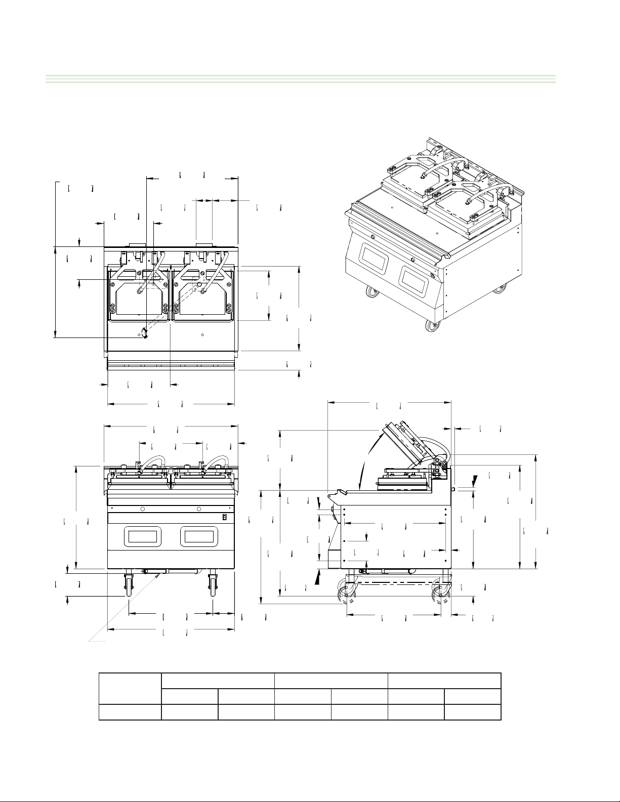
Dimensions: Models MWE2W-1, MWG2W-1
*CABLE ENTRANCE(S) VARY SLIGHTLY DEPENDING ON UNIT CONFIGURATION
25.95in
23.69in
602mm
BOTTOM GAS ONLY
INLET 3/4" NPT
9.25in
235mm
*BOTTOM CABLE
ENTRANCE
14.11in
358mm
*BOTTOM
CABLE
ENTRANCE
659mm
BOTTOM GAS ONLY
INLET 3/4" NPT
4.64in
118mm
TYP. GAS
ONLY
7.18in
182mm
TYP. GAS
ONLY
14.06in
357mm
PLATEN DEPTH
PLATE DEPTH
24.00in
610mm
29.15in
740mm
6.40in
163mm
GAS ONLY
17.53in
445mm
PLATEN WIDTH
FRONT GAS CONNECTION KIT
GAS ONLY
36.00in
914mm
PLATE WIDTH
38.00in
965mm
18.00in
457mm
23.82in
605mm
36.03in
915mm
10.00in
254mm
32.25in
819mm
MAX. COOK
HEIGHT
6.10in
155mm
17.000in
432mm
MAX. OP.
30.00in
762mm
MIN. COOK
HEIGHT
5.48in
139mm
1.50in
38mm
2.25in
57mm
13.06in
332mm
46.8°
MAX. OP.
5.56in
141mm
34.96in
888mm
28.76in
731mm
26.68in
678mm
1.53in
39mm
GAS ONLY
22.10in
561mm
GAS ONLY
7.75in
197mm
2.92in
74mm
.97in
25mm
.93in
24mm
GAS ONLY
29.41in
747mm
PLATEN
DOWN
32.38in
823mm
PLATEN
UP
Page 8
MODEL
HEIGHT* WIDTH DEPTH
inches mm inches mm inches mm
MWE2W-1 29.2 740 36.0 915 34.9 887
*Height not including casters
Part #4530667 Rev 4 (30 Jan 15)
Page 9
GARLAND CLAMSHELL GRILLS WITH PRODUCT RECOGNITION INSTALLATION/OPERATION MANUAL-1&2 PLATEN
DIMENSION SPECIFICATION
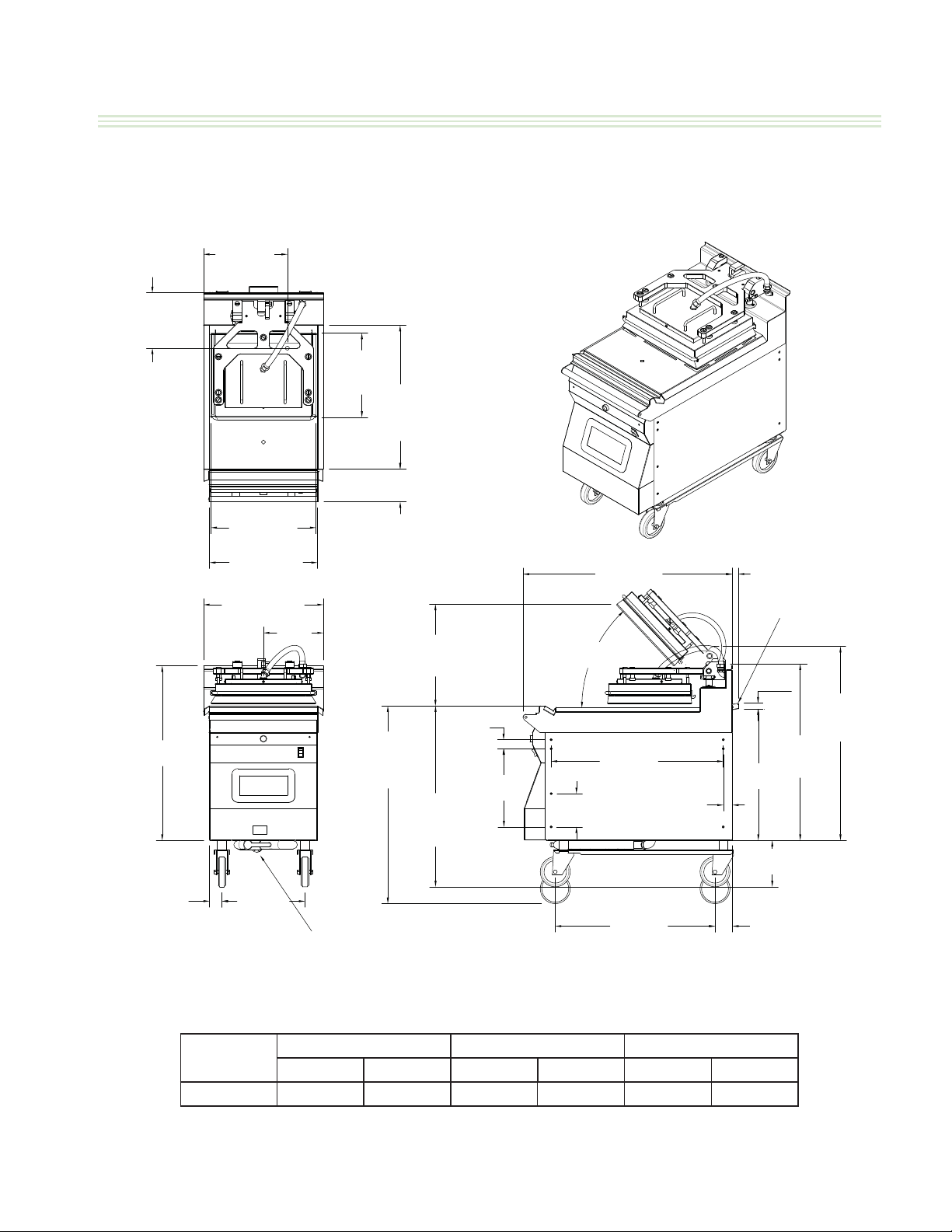
Dimensions: Models: MWE1W-1, MWG1W-1
14.11"
(358mm)
BOTTOM CABLE
ENTRANCE
9.25"
(235mm)
BOTTOM CABLE
ENTRANCE
14.06"
(357mm)
PLATTEN
DEPTH
24.00"
(610mm)
PLATE
DEPTH
5.48"
(139mm)
17.53"
(445mm)
PLATTEN WIIDTH
29.15"
(741mm)
18.00"
(457mm)
PLATE WIIDTH
20.00"
(508mm)
(254mm)
10.00"
33.00"
(838mm)
MAX COOK
HEIGHT
17.00"
(432mm)
MAX OPEN
30.75"
(781mm)
MIN COOK
HEIGHT
1.50"
(38mm)
13.06"
(332mm)
(888mm)
46.8° MAX OPEN
(731mm)
5.56"
(141mm)
34.96"
28.76"
1.53"
(39mm)
.97
(559mm)
(25mm)
.93"
(24mm)
22"
8.50"
(216mm)
GAS ONLY
29.41"
(747mm)
PLATTEN
DOWN
32.38"
(823mm)
PLATTEN
UP
2.06"
(52mm)
13.88"
(353mm)
MODEL
MWE1W-1 29.2 740 18.0 457 34.9 887
*Height not including casters
Part #4530667 Rev 4 (30 Jan 15)
FRONT GAS CONNECTION KIT
GAS ONLY
26.68"
(678mm)
2.92"
(74mm)
HEIGHT* WIDTH DEPTH
inches mm inches mm inches mm
Page 9
Page 10

INSTALLATION/OPERATION MANUAL-1&2 PLATEN GARLAND CLAMSHELL GRILLS WITH PRODUCT RECOGNITION
DIMENSION SPECIFICATION
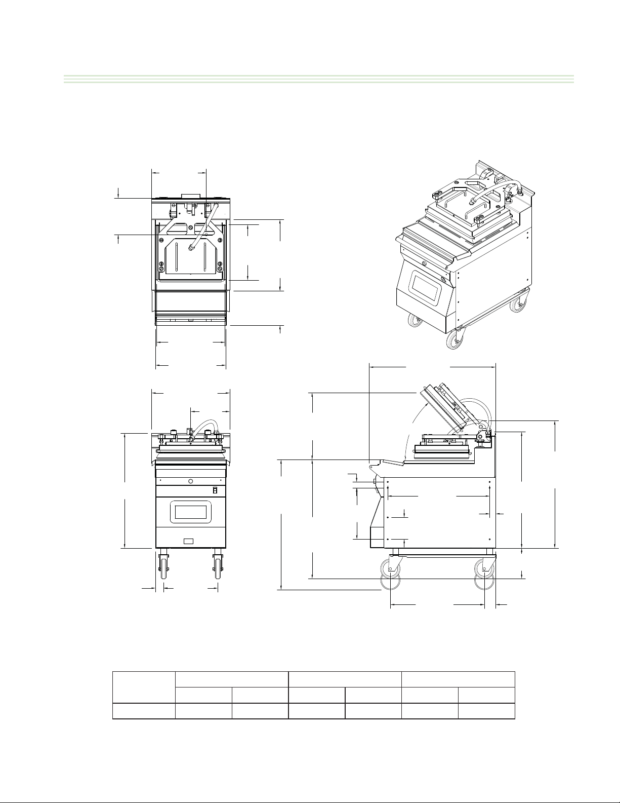
Dimensions: Model MWE2S-1
*CABLE ENTRANCE(S) VARY SLIGHTLY DEPENDING ON UNIT CONFIGURATION
14.11in
358mm
*BOTTOM
CABLE
ENTRANCE
11.28in
287mm
*BOTTO M CABLE
ENTRANCE
14.06in
357mm
PLATEN DEPTH
17.00in
432mm
PLATE DEPTH
29.15in
740mm
17.53in
445mm
PLATEN
WIDTH
36.00in
914mm
PLATE WIDTH
38.00in
965mm
18.00in
457mm
23.82in
605mm
36.03in
10.00in
254mm
MAX. COOK
6.10in
155mm
33.00in
838mm
HEIGHT
8.51in
216mm
17.000in
432mm
MAX. OP.
1.50in
38mm
30.75in
781mm
MIN. COOK
HEIGHT
2.25in
57mm
13.06in
332mm
46.8°
MAX. OP.
5.56in
141mm
31.02in
787mm
24.71in
628mm
24.00in
610mm
1.53in
39mm
29.41in
747mm
PLATEN
DOWN
8.50in
216mm
32.38in
823mm
PLATEN
UP
2.92in
74mm
Page 10
MODEL
HEIGHT* WIDTH DEPTH
inches mm inches mm inches mm
MWE2S-1 29.2 740 36.0 915 31.0 787
*Height not including casters
Part #4530667 Rev 4 (30 Jan 15)
Page 11
GARLAND CLAMSHELL GRILLS WITH PRODUCT RECOGNITION INSTALLATION/OPERATION MANUAL-1&2 PLATEN
DIMENSION SPECIFICATION
Dimensions: Model MWE1S-1
14.11"
(358mm)
BOTTOM CABLE
ENTRANCE
9.25"
(235mm)
BOTTOM CABLE
ENTRANCE
14.06"
17.53"
(445mm)
PLATTEN WIIDTH
18.00
(457mm)
PLATE WIIDTH
20.00"
(508mm)
10.00
(254mm)
(357mm)
PLATTEN
DEPTH
17.00"
(432mm)
PLATE
DEPTH
8.50"
(216mm)
17.00
(432mm)
MAX OPEN
31.00"
(787mm)
46.8° MAX OPEN
1.50"
30.75"
(781mm)
MIN COOK
HEIGHT
(38mm)
13.06"
(332mm)
5.56"
(141mm)
24.72"
(628mm)
24.00"
(610mm)
(39mm)
29.15"
(741mm)
2.06"
(52mm)
MODEL
33.00"
(838mm)
MAX COOK
HEIGHT
13.88"
(353mm)
HEIGHT* WIDTH DEPTH
inches mm inches mm inches mm
MWE2S-1 29.2 740 18.0 457 31.0 787
*Height not including casters
1.53"
29.41"
(747mm)
PLATTEN
DOWN
8.50"
(216mm)
2.92"
(74mm)
32.38"
(823mm)
PLATTEN
UP
Part #4530667 Rev 4 (30 Jan 15)
Page 11
Page 12
INSTALLATION/OPERATION MANUAL-1&2 PLATEN GARLAND CLAMSHELL GRILLS WITH PRODUCT RECOGNITION
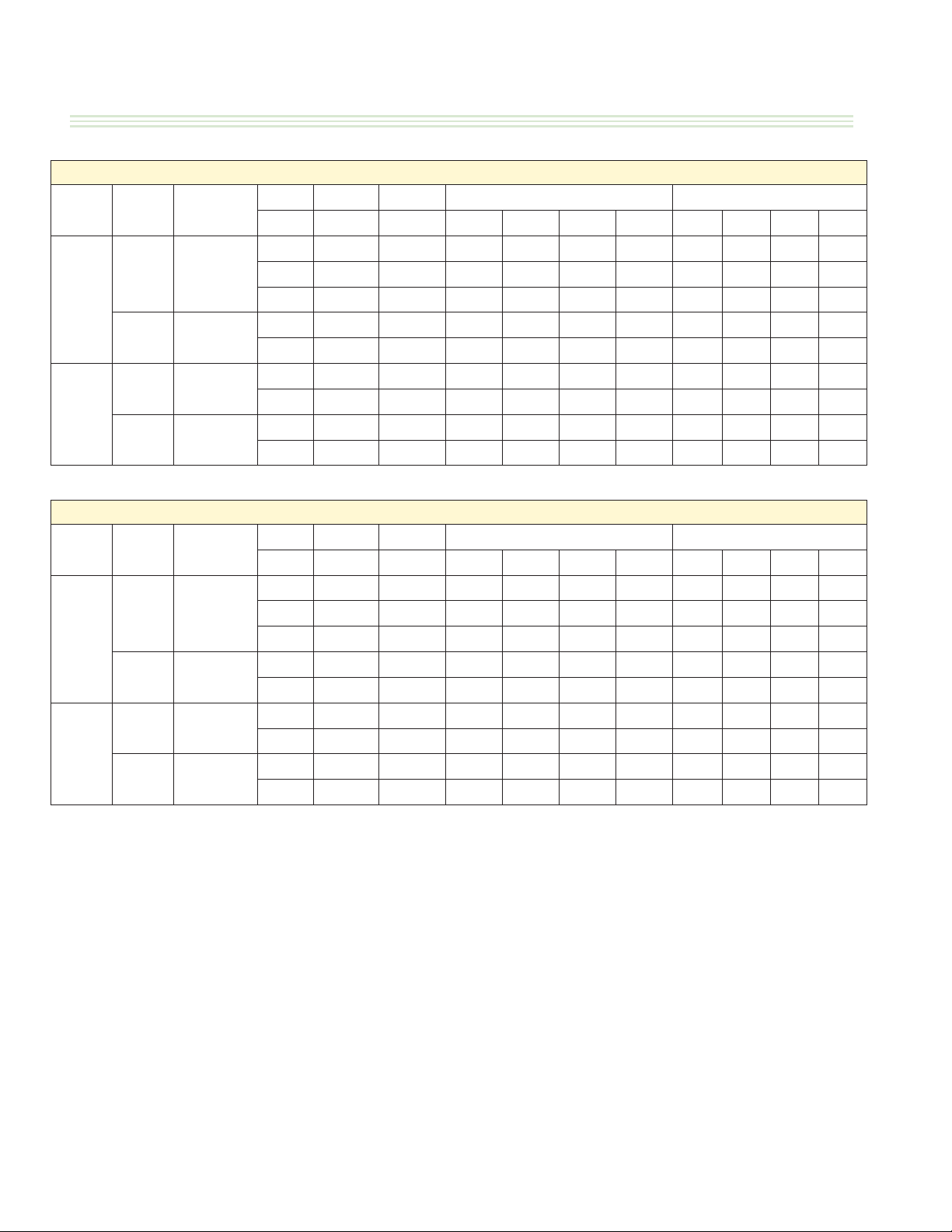
ELECTRICAL INPUT SPECIFICATIONS - DELTA
DELTA - 208 Volts Models
Model Drawing
Electric 4530506
2
Platen
Gas 4530508
Electric 4530516
1
Platen
Gas 4530513
Model Drawing
Electric 4530506
2
Platen
Gas 4530508
Electric 4530516
1
Platen
Gas 4530513
TB1 400 3.5 3.5 3.9 11.0 29.4 31.1 31.1
TB2 52 0.1 0.4
TB3 3.5 3.5 3.5 10.6 29.4 29.4 29.4
TB1 400 3.7 3.7 4.1 11.6 31.1 32.8 32.8
TB2 253.6 0.3 2.1
TB1 200 3.5 3.5 3.7 10.8 29.4 30.3 30.3
TB2 26 0.0 0.2
TB1 200 1.9 1.9 2.1 5.8 15.5 16.4 16.4
TB2 126.8 0.1 1.1
TB1 400 3.5 3.5 3.9 11.0 27.8 29.4 29.4
TB2 52 0.1 0.4
TB3 3.5 3.5 3.5 10.6 27.8 27.8 27.8
TB1 400 3.7 3.7 4.1 11.6 29.4 31.0 31.0
TB2 253.6 0.3 2.0
TB1 200 3.5 3.5 3.7 10.8 27.8 28.6 28.6
TB2 26 0.0 0.2
TB1 200 1.9 1.9 2.1 5.8 14.7 15.5 15.5
TB2 126.8 0.1 1.0
Control MCB Total loads Kw Amps/line
I/E L1-L3 L1-L2 L2-L3 L3-L1 All Ctrl L1 L2 L3
DELTA - 220 Volts Models
Control MCB Total loads Kw Amps/line
I/E L1-L3 L1-L2 L2-L3 L3-L1 All Ctrl L1 L2 L3
Page 12
Part #4530667 Rev 4 (30 Jan 15)
Page 13

GARLAND CLAMSHELL GRILLS WITH PRODUCT RECOGNITION INSTALLATION/OPERATION MANUAL-1&2 PLATEN
ELECTRICAL INPUT SPECIFICATIONS - DELTA (continued)
DELTA - 230 Volts Models
Model Drawing
Electric 4530506
2
Platen
Gas 4530508
Electric 4530516
1
Platen
Gas 4530513
Model Drawing
Electric 4530506
2
Platen
Gas 4530508
Electric 4530516
1
Platen
Gas 4530513
TB1 400 3.3 3.3 3.7 10.4 25.1 26.6 26.6
TB2 52 0.1 0.4
TB3 3.3 3.3 3.3 10.0 25.1 25.1 25.1
TB1 400 3.7 3.7 4.1 11.4 27.6 29.1 29.1
TB2 253.6 0.3 1.9
TB1 200 3.3 3.3 3.5 10.2 25.1 25.8 25.8
TB2 26 0.0 0.2
TB1 200 1.8 1.8 2.0 5.7 13.8 14.6 14.6
TB2 126.8 0.1 1.0
TB1 400 3.5 3.5 3.9 11.0 25.5 27.0 27.0
TB2 52 0.1 0.4
TB3 3.5 3.5 3.5 10.6 25.5 25.5 25.5
TB1 400 3.7 3.7 4.1 11.6 26.9 28.4 28.4
TB2 253.6 0.3 1.8
TB1 200 3.5 3.5 3.7 10.8 25.5 26.2 26.2
TB2 26 0.0 0.2
TB1 200 1.9 1.9 2.1 5.8 13.5 14.2 14.2
TB2 126.8 0.1 0.9
Control MCB Total loads Kw Amps/line
I/E L1-L3 L1-L2 L2-L3 L3-L1 All Ctrl L1 L2 L3
DELTA - 240 Volts Models
Control MCB Total loads Kw Amps/line
I/E L1-L3 L1-L2 L2-L3 L3-L1 All Ctrl L1 L2 L3
Part #4530667 Rev 4 (30 Jan 15)
Page 13
Page 14

INSTALLATION/OPERATION MANUAL-1&2 PLATEN GARLAND CLAMSHELL GRILLS WITH PRODUCT RECOGNITION
ELECTRICAL INPUT SPECIFICATIONS - WYE
WYE - 380 Volts Models
Model Drawing
2
Platen
Electric
Std
Electric
China
Electric
Slim
4530507
4530517
4530510
Gas 4530509
1
Platen
Electric
Std
Electric
Slim
4530514/
4530515
4530511
Gas 4530512
TB1 400 7.5 7.1 7.1 21.6 34.0 32.2 32.2
TB2 52 0.1 0.2
TB1 400 3.9 3.5 3.5 11.0 17.9 16.1 16.1
TB2 52 0.1 0.2
TB3 3.5 3.5 3.5 10.6 16.1 16.1 16.1
TB1 400 7.5 4.6 4.6 16.6 34.0 20.8 20.8
TB2 52 0.1 0.2
TB1 400 4.1 3.7 3.7 11.6 18.8 17.0 17.0
TB2 253.6 0.3 1.2
TB1 200 3.7 3.5 3.5 10.8 17.0 16.1 16.1
TB2 26 0.0 0.1
TB1 200 3.7 3.5 1.0 8.3 17.0 16.1 4.7
TB2 26 0.0 0.1
TB1 200 2.1 1.9 1.9 5.8 9.4 8.5 8.5
TB2 126.8 0.1 0.6
Control MCB Total loads Kw Amps/line
I/E L1-N L1 L2 L3 All Ctrl L1 L2 L3
Model Drawing
2
Platen
Electric
Std
Electric
China
Electric
Slim
4530507
4530517
4530510
Gas 4530509
1
Platen
Electric
Std
Electric
Slim
4530514/
4530515
4530511
Gas 4530512
WYE - 400 Volts Models
Control MCB Total loads Kw Amps/line
I/E L1-N L1 L2 L3 All Ctrl L1 L2 L3
TB1 400 7.1 6.7 6.7 20.4 30.6 28.8 28.8
TB2 52 0.1 0.2
TB1 400 3.7 3.3 3.3 10.4 16.1 14.4 14.4
TB2 52 0.1 0.2
TB3 3.3 3.3 3.3 10.0 14.4 14.4 14.4
TB1 400 7.1 4.4 4.4 15.8 30.6 18.9 18.9
TB2 52 0.1 0.2
TB1 400 4.1 3.7 3.7 11.4 17.6 15.9 15.9
TB2 253.6 0.3 1.1
TB1 200 3.5 3.3 3.3 10.2 15.3 14.4 14.4
TB2 26 0.0 0.1
TB1 200 3.5 3.3 1.0 7.9 15.3 14.4 4.5
TB2 26 0.0 0.1
TB1 200 2.0 1.8 1.8 5.7 8.8 7.9 7.9
TB2 126.8 0.1 0.5
Page 14
Part #4530667 Rev 4 (30 Jan 15)
Page 15

GARLAND CLAMSHELL GRILLS WITH PRODUCT RECOGNITION INSTALLATION/OPERATION MANUAL-1&2 PLATEN
ELECTRICAL INPUT SPECIFICATIONS - WYE (continued)
WYE - 415 Volts Models
Model Drawing
2
Platen
Electric
Std
Electric
China
Electric
Slim
4530507
4530517
4530510
Gas 4530509
1
Platen
Electric
Std
Electric
Slim
4530514/
4530515
4530511
Gas 4530512
TB1 400 7.5 7.1 7.1 21.6 31.2 29.5 29.5
TB2 52 0.1 0.2
TB1 400 3.9 3.5 3.5 11.0 16.4 14.7 14.7
TB2 52 0.1 0.2
TB3 3.5 3.5 3.5 10.6 14.7 14.7 14.7
TB1 400 7.5 4.6 4.6 16.6 31.2 19.1 19.1
TB2 52 0.1 0.2
TB1 400 4.1 3.7 3.7 11.6 17.2 15.6 15.6
TB2 253.6 0.3 1.1
TB1 200 3.7 3.5 3.5 10.8 15.6 14.7 14.7
TB2 26 0.0 0.1
TB1 200 3.7 3.5 1.0 8.3 15.6 14.7 4.3
TB2 26 0.0 0.1
TB1 200 2.1 1.9 1.9 5.8 8.6 7.8 7.8
TB2 126.8 0.1 0.5
Control MCB Total loads Kw Amps/line
I/E L1-N L1 L2 L3 All Ctrl L1 L2 L3
Part #4530667 Rev 4 (30 Jan 15)
Page 15
Page 16
INSTALLATION/OPERATION MANUAL-1&2 PLATEN GARLAND CLAMSHELL GRILLS WITH PRODUCT RECOGNITION
GAS INPUT SPECIFICATIONS
GAS Grills, 2 Platen MWG2W-1 North America:
GAS INPUT
MAX INPUT
GAS
NATURAL GAS 32,000 64,000 #35 50% 7.0 3.5
PROPANE 32,000 64,000 1.75mm 50% 11.0 10.0
NET PER
BURNER
BTU/H
TOTAL INPUT
RATING
BTU/H
INJECTOR
SIZE
AIR SHUTTER
SETTING
*
SUPPLY
PRESSURE
IN W.C.
BURNER
MANIFOLD
PRESSURE
IN W.C.
GAS Grills, 2 Platen MWG2W-1 CE Approved Model:
GAS INPUT
MAX INPUT
GAS GROUP
G20 NG 8.6 17.2 2.64mm 9.0 20/25 8.7 1.82m3/h
G31 LPG 8.6 17.2 1.61mm 9.0 37/50 24.9 1.34kg/h
CATEGORY DESTINATION COUNTRIES SUPPLY PRESSURE (mbar)
NET PER
BURNER kW
I
2H
I
2E
I
3P
I
3P
I
3P
TOTAL INPUT
RATING kW
AT, CH, CZ, DK, ES, FI, GB, IE, IS, IT, NO, PT, SE 20
INJECTOR
SIZE
BE, CH, CZ, ES, FR, GB, GR, IE, LU 37
BE, CH, DE, CZ, ES, FR, NL 50
AIR SHUTTER
SETTING mm
*
GAS CATEGORIES
DE, LU 20
NL 30
SUPPLY
PRESSURE
mbar
BURNER
PRESSURE
mbar
VOLUMETRIC
GAS RATE
(*) NOTE: Air shutter setting may vary by region. Only a qualify service technician should make adjustments
for proper combustion
Page 16
Part #4530667 Rev 4 (30 Jan 15)
Page 17

GARLAND CLAMSHELL GRILLS WITH PRODUCT RECOGNITION INSTALLATION/OPERATION MANUAL-1&2 PLATEN
GAS INPUT SPECIFICATIONS (continued)
GAS SINGLE PLATEN MWG1W-1 Grills, North America:
GAS INPUT
MAX INPUT
GAS
NATURAL GAS 32,000 32,000 #35 50% 7.0 3.5
PROPANE 32,000 32,000 1.75mm 50% 11.0 10.0
NET PER
BURNER
BTU/H
TOTAL INPUT
RATING
BTU/H
INJECTOR
SIZE
AIR SHUTTER
SETTING
*
SUPPLY
PRESSURE
IN W.C.
BURNER
MANIFOLD
PRESSURE
IN W.C.
GAS SINGLE PLATEN MWG1W-1 Grills, CE Approved Model:
GAS INPUT
MAX INPUT
GAS GROUP
G20 NG 8.6 8.6 2.64mm 9.0 20/25 8.7 0.91m3/h
G31 LPG 8.6 8.6 1.61mm 9.0 37/50 24.9 0.67kg/h
CATEGORY DESTINATION COUNTRIES SUPPLY PRESSURE (mbar)
NET PER
BURNER kW
I
2H
I
2E
I
3P
I
3P
I
3P
TOTAL INPUT
RATING kW
AT, CH, CZ, DK, ES, FI, GB, IE, IS, IT, NO, PT, SE 20
INJECTOR
SIZE
BE, CH, CZ, ES, FR, GB, GR, IE, LU 37
BE, CH, DE, CZ, ES, FR, NL 50
AIR SHUTTER
SETTING mm
*
GAS CATEGORIES
DE, LU 20
NL 30
SUPPLY
PRESSURE
mbar
BURNER
PRESSURE
mbar
VOLUMETRIC
GAS RATE
(*) NOTE: Air shutter setting may vary by region. Only a qualify service technician should make adjustments
for proper combustion
Part #4530667 Rev 4 (30 Jan 15)
Page 17
Page 18

INSTALLATION/OPERATION MANUAL-1&2 PLATEN GARLAND CLAMSHELL GRILLS WITH PRODUCT RECOGNITION
INSTALLATION & STARTUP
General:
• In Canada or USA: The installation must comply with
local codes, or in the absence of local codes, with
the National Fuel Gas Code, ANSI Z223.1/NFPA 54, or
the Natural Gas and Propane Installation Code, CSA
B149.1, as applicable
• The appliance and its individual shut-o (supplied by
others) must be disconnected from the gas supply
piping system during any pressure testing of that
system at pressures in excess of 1/2 PSIG (3.45 KPA).
• The appliance must be isolated from the gas supply
piping by closing its individual manual shut-o
(supplied by others) during any pressure testing of the
gas supply piping system at test pressures equal to or
less than 1/2PSIG (3.45KPA)
Installation Store Responsibilities:
• The installation shall be made with a connector
that complies with the Standard for Connectors for
Moveable Gas Appliances, ANSI Z21.69/CSA 6.16,
and quick-disconnects device that complies with the
Standard for Quick Disconnects for Use with Gas Fuel,
ANSI Z21.41/CSA 6.9.
• The front Casters on the appliance are equipped with
brakes to limit the movement of the appliance without
placing any strain on the connector or quick disconnect
device or its associated piping.
• Please be aware: required restraint is attached to a
bracket, (which is located on the rear caster closest
to the gas connection) and if disconnection of the
restraint is necessary, be sure to reconnect the device
after the appliance has been returned to its original
position.
• “Adequate clearance must be provide for air opening
into the combustion chamber, and for proper servicing”
• Not intended to be installed adjacent to combustible
walls or on combustible oors.
• Ensure grill has been installed by a competent trained
installation person.
• Ensure store readiness of utilities, product & personnel.
• Contacting your local Garland Factory Authorized
Service Center for a startup date.
• Participate in the startup to ensure a successful startup
and familiarity with the grill.
• Conduct training with your crew personnel to ensure
maximum utilization of the grill.
Once the installation is complete as per the procedures
below, a factory authorized service company MUST startup
the grill according to Garland Commercial Ranges startup
standards.
A startup DOES NOT include:
1. Uncrating the unit
2. Placing the unit in its position under the exhaust hood.
3. Leveling the grill on the oor under the exhaust hood.
4. Attaching the supply cord(s) unless supplied by the
factory.
5. Making adjustments to the ventilation system.
6. Sheet metal work required due to improper exhaust
hood application.
7. Adjusting the grill to achieve beef integrity that
deviates from the McDonalds standard.
A start-up DOES include:
1. Veri cation of supply voltage and, if applicable gas
supply.
2. Leak test and as pressure check on gas grills.
3. Electrical safety check.
4. Verifying operation of grill by allowing unit to attain set
temperature.
5. Verify operation of platens, if applicable, and timer
functions.
6. Ensure time out alarm is functional and platens raise (if
applicable)
7. Set proper gas and verify with beef integrity check that
two consecutive runs yield the approved beef integrity
results as per McDonalds standards.
8. Conduct brief training to store manager on the
operation of the grill.
WARNING: PLEASE READ INSTALLATION INSTRUCTIONS CAREFULLY. FAILURE TO PERFORM
THESE STEPS CAN RESULT IN EQUIPMENT FAILURE, DAMAGE AND / OR VOID OF WARRANTY.
Page 18
Part #4530667 Rev 4 (30 Jan 15)
Page 19

GARLAND CLAMSHELL GRILLS WITH PRODUCT RECOGNITION INSTALLATION/OPERATION MANUAL-1&2 PLATEN
INSTALLATION & STARTUP (continued)
Items included with the purchase of your
new grill from manufacturer:
1. One (1) World Grill 1 platen gas & electric included the
following list, except countries mentioned;
1 PLATEN
Part # Description
4527294
4527294
4526436 Te on Bar, Rear 1 1
4526436 Te on Bar, Rear (Japan Only) 1 0
4527646 Splash Shield 1 1
4527646 Splash Shield (Japan Only) 1 0
4527642
1799301 Te on Sheet (MWG/E) 0 3
Te on Sheet Clips
(Japan not included)
Te on Sheet Clips
(Japan Only)
Te on Release Sheet
(Japan included)
Wrap
Around
Part # Description
4517563
1792003
4523352
4526478
5” Front Swivel Caster w/Brake
5” Rear Swivel Caster
Leg Brace Locking Bracket - Standard
Leg Brace Locking Bracket - Slim
2. One (1) World Grill 2 platen gas & electric included the
following list, except countries mentioned
Non-Wrap
Around
42
40
30
Qty
2
2
1
1
Items NOT INCLUDED from the manufacturer
and should be purchased from the KES:
1. Any electrical cords needed for application.
2. Any ue box needed for application.
3. Any grease buckets or grease rails needed for
application.
THE FOLLOWING INSTALLATION
PROCEDURE CAN BE PERFORMED BY A:
• FACTORY AUTHORIZED SERVICE CENTER
• AN APPROVED INSTALLATION PERSON APPROVED BY
PURCHASER OF GRILL
• LICENSED INSTALLER CONTRACTED BY KES (KITCHEN
EQUIPMENT SUPPLIER)
• CONTACT LOCAL GARLAND FACTORY AUTHORIZED
SERVICE CENTER FOR MORE DETAIL
Uncrate unit from crating material.
CAUTION:
PRIOR TO INSTALLATION, CHECK THE ELECTRICAL
SUPPLY TO ENSURE INPUT VOLTAGE AND PHASE
MATCH THE EQUIPMENT VOLTAGE RATING AND
PHASE. MANY LOCAL CODES EXIST, IT IS THE
RESPONSIBILITY OF THE OWNER/INSTALLER TO
COMPLY WITH THESE CODES.
2 PLATEN
Part # Description
4527294
4527294
4526436 Te on Bar, Rear 2 2
4526436 Te on Bar, Rear (Japan Only) 2 0
4527646 Splash Shield 2 2
4527646 Splash Shield (Japan Only) 2 0
4527642
1799301 Te on Sheet (MWG/E) 0 6
Te on Sheet Clips
(Japan not included)
Te on Sheet Clips
(Japan Only)
Te on Release Sheet
(Japan included)
Wrap
Around
Part # Description
4517563
1792003
4523352
4526478
5” Front Swivel Caster w/Brake
5” Rear Swivel Caster
Leg Brace Locking Bracket - Standard
Leg Brace Locking Bracket - Slim
Non-Wrap
Around
84
80
60
Qty
NOTE: ENSURE THAT PLATENS ARE STRAPPED
DOWN SECURELY THROUGH STEP 3 TO PREVENT
PLATENS FROM RAISING. SEVERE DAMAGE MAY
OCCUR.
1
2
3
4
2
2
1
1
Note:
ĺUnpack Unit (Single or Double Platen), Only
Cut Straps That Secure Unit To Pallet.
ĺDO NOT Remove Brace 1 & 2, AND DO NOT
CUT STRAPS 3 & 4.
4
Part #4530667 Rev 4 (30 Jan 15)
Page 19
Page 20

INSTALLATION/OPERATION MANUAL-1&2 PLATEN GARLAND CLAMSHELL GRILLS WITH PRODUCT RECOGNITION
INSTALLATION & STARTUP (continued)
5. Tip unit over on its back. Install casters & channels as
WARNING, HEAVY OBJECT!
The following procedure will require use of
lifting aids and proper lifting technique when
removing or replacing. To avoid serious
injuries use assistance when moving or lifting.
Installation of Casters
1. Put a pair of heavy gloves to protect your hands and
wear a lumbar support for lower back. Safety is the
rst concern when moving a heavy grill since it weigh
approximately 950lbs (431kg) or more.
2. Next procedure will require use of lifting aids and
proper lifting/moving techniques. Slide the grill away
from walls.
3. Check out the leg brace locking bracket included with
your purchased, Ensure you understand the front and
the back as shown below.
shown diagram below. Bracket notch facing the oor.
WARNING:
It is recommended that the rear casters are
screwed in all the way before tipping.
4. Check out the caster included with your purchased,
Ensure you understand the front and the rear casters as
shown below.
Page 20
6. Block back caster in place to avoid the unit sliding
forward or backward.
7. Carefully rotate grill back on its casters. Now you may
cut and remove the platen securing straps.
8. Remove back body side and Install power cords per
your country / area’s speci cations.
Part #4530667 Rev 4 (30 Jan 15)
Page 21

GARLAND CLAMSHELL GRILLS WITH PRODUCT RECOGNITION INSTALLATION/OPERATION MANUAL-1&2 PLATEN
INSTALLATION & STARTUP (continued)
WARNING:
The appliances must be electrically grounded in accordance with local codes, or in the absence of local codes,
with the National Electrical Code ANSI/NFPA 70, or the Canadian Electrical Code CSA C22.1 as applicable.
POWER SUPPLY CONNECTION:
All electric connections must be made by a quali ed,
properly equipped technician.
NOTE: WIRING DIAGRAM LOCATED INSIDE
LOWER FRONT PANEL.
“DISCONNECT POWER BEFORE OPENING”
Electrical Cable Hookup
DUAL POWER SUPPLY CONNECTION
USA & some other
MWG2W HAS ONE ELECTRICAL CORD.
MWE2W HAS TWO ELECTRICAL CORDS.
POWER CORDS & PLUGS
ARE NOT SUPPLIED
BY THE MANUFACTURER
Electrical Cable Hookup
SINGLE POWER SUPPLY CONNECTION
where required by local regulations
POWER CORDS & PLUGS
ARE NOT SUPPLIED
BY THE MANUFACTURER
INPUT 1
INPUT 1
INPUT 2
INPUT 2
Part #4530667 Rev 4 (30 Jan 15)
Hood-Interlock & Control Power Supply; where applicable
1 x 20AMP NEMA 21-20
POWER CORDS
ARE NOT SUPPLIED
BY THE
MANUFACTURER
EEL1 L1 L1 L1
L1 L1 L1 L1
WhWht
Wht
Wht Wht Wht
tWhtWht
Ora Red
Ora Red Blk
Page 21
Blk
Page 22

INSTALLATION/OPERATION MANUAL-1&2 PLATEN GARLAND CLAMSHELL GRILLS WITH PRODUCT RECOGNITION
INSTALLATION & STARTUP (continued)
Important Note:
Mennekes option is available only in some con gurations, check with your supplier for more details.
Mennekes 3 & 5 Pins (Option 1)
Connector Pins Intended Load Connected to
Mennekes
5 Pins
Mennekes
3 Pins
L3-TB1
N-TB1
Grill and Platen
1,2,3,4,
GND
1,2,GND
MENNEKES 5-PIN OPTION
Heaters
~3N 380/400/415
32Amps
50/60Hz
~1N 120-250 VAC,
16A
Control loads (N3,
MCB, Ignition
controller, blower,
gas valve)
3
2
4
1
E-TB1
TB1
L1, L2, L3, N,
GND
TB2
Orange &
White Replace
jumpers J-N
and J-L1
L2-TB1
L1-TB1
Mennekes 7 Pins (Option 2)
Connector Pins Intended Load Connected to
Mennekes
7 Pins
N-TB1
BLK-TB2
4
5
1,2,3,4,
GND
5,6
RED-TB2
Grill and Platen
Heaters
~3N 380/400/415
32Amps
50/60Hz
Swicth, Pilot duty
only
10A 250VAC, 15A
125VAC, 12(6)A
250VAC T85
MENNEKES 7-PIN OPTION
L3-TB1
3
4
2
6
5
3-Y 380/400/415, 50/60HZ
1
E-TB1
TB1
L1, L2, L3, N,
GND
TB2
Black & Red
L2-TB1
L1-TB1
WHT-TB2
Page 22
3-Y 380/400/415, 50/60HZ
MENNEKES 3-PIN OPTION
2
L-N 220/230/240, 50/60HZ
1
E-TB2
ORA-TB2
Terminal Blocks Diagram
TO SWITCH
TB1
E
N
N
TO CONTACTORS
L1
TO MENNEKES
L2
L3
Part #4530667 Rev 4 (30 Jan 15)
J-L1
J-N
TB2
4
BLK
RED
ORA
WHT
WHT
WHT
WHT
4
TO MENNEKES
(7 PINS)
55
L1
L1
L1
L1
E
Page 23

GARLAND CLAMSHELL GRILLS WITH PRODUCT RECOGNITION INSTALLATION/OPERATION MANUAL-1&2 PLATEN
INSTALLATION & STARTUP (continued)
9. Install Front Gas connection: Isolate grill from any
power source by unplugging all electrical connections.
A. Rotate existing elbow as shown in the diagrams
below.
B. Attach support bracket (PN 4528775)to base
as shown with #10-24 screws and lock washers
supplied.
NOTE: For retro t applications, drill 2x .161 holes and
use self tapping screws provided.
C. Install 3/4” NPT nipple through support bracket and
onto existing elbow. Attach locking ring with 2x
#10-24 screws.
D. Install connector 3 inches long (Used on single
platen Only)
E. Install elbow to orientation show below.
F. Install nipple.
G. Attach ex gas hose to nipple.
10. Install shut o sticker as shown above to bottom of
front control panel.
G
1.500 9.0
1.75 REF
30°
Connect the hose and ensure the sleeve snaps fully
forward against the retaining ring.
With the manual shut-o valve closed, install the
other end of the hose to the gas supply. If the grill
is equipped with an optional front gas connection,
see the sub-section titled, “Front Gas Connection” on
the following page for dimensions and positioning
information.
12. Install ue box to back of grill for single or double
platen (If required).
FOR GAS GRILLS ONLY
FLUE BOX CLIPS ON REAR LIP OF
GRILL & IS CENTERED SIDE TO SIDE
E
6.00
F
E
12 REF
B
C
A
INSTALL ELBOW #1026715 TO
ORIENTATION SHOWN
11. GAS GRILL ONLY, (for electric grills, skip to step 8 ):
Install the included quick-disconnect gas hose to the
inlet tting on the underside of the grill by threading
brass male quick-connect coupler included with the
hose onto the factory-installed elbow.
FLEXIBLE GAS HOSE
GAS
FLOW
TO GAS
SUPPLY
FACTORY
INSTALLED
GAS INLET
UNDERNEATH GRILL
MALE COUPLER
[INSTALL FIRST]
D
A
13. Attached Shut-O sticker as shown below:
14. Install grease bucket rails as shown below:
FLUE BOX IS NOT SUPPLIED
BY THE MANUFACTURER
Attached
Shut-O
Sticker
In This
Location
Part #4530667 Rev 4 (30 Jan 15)
Page 23
Page 24

INSTALLATION/OPERATION MANUAL-1&2 PLATEN GARLAND CLAMSHELL GRILLS WITH PRODUCT RECOGNITION
INSTALLATION & STARTUP (continued)
INSTALL GREASE BUCKET RAILS & GREASE BUCKET AS SHOWN
RAIL
GREASE BUCKETS & RAILS NOT
SUPPLIED BY MANUFACTURER
GREASE BUCKET
15. Roll grill under hood. Grill must be level front to back,
side to side and diagonally. Adjust casters accordingly
to obtain nal level.
Hood Type & Platen Height
With the platens in the raised position, measure the height
from the front edge of the platen to the grill surface. If the
platen height is over 17” (431mm), it must be adjusted to
proper clearance by an authorized service agent.
Setting the Proper Combustion Levels
Using the following procedure will ensure
that the proper O2, CO2, & CO levels are
reached. Combustion level checks and
adjustments should only be performed by a
quali ed technicians employed by a factory
authorized service center.
1. Remove control panel and lower front panel. Set on
oor, leaving all connections in place.
2. The regulator comes set at 3.5” W.C (0.864 kPa) or 10.0”
W.C. (0.249kPa), depending on type of gas. Verify
pressure settings at the test spigot on each gas valve
and adjust the regulator as needed..
3. Slightly loosen nut holding butter y air shutter
adjuster on the combustion air blower connected to
the burner being adjusted just enough that it can be
rotated but will stay in place when force is removed.
Air shutter openings are factory set and marked with
a line on the blower face. Note if the air shutter has
been moved from this reference line. When marking
the blower face with reference lines in the following
steps, make them on the opposite side of where the
factory mark exists.
Page 24
17in
[431mm]
MAX
45°
Part #4530667 Rev 4 (30 Jan 15)
Page 25

GARLAND CLAMSHELL GRILLS WITH PRODUCT RECOGNITION INSTALLATION/OPERATION MANUAL-1&2 PLATEN
INSTALLATION & STARTUP (continued)
4. From a cold start, turn
on zone for the burner
being checked and
allow it to run for 1
minute to stabilize.
If the grill is already
preheated, add a load
to the surface to keep
burner operating for
several minutes. With
burner operating,
adjust the air shutter
to a more closed
position until the
ame begins to lift or
oat o the burner
surface.
5. Mark a line on the
blower face along the
edgwe of the shutter
from the air opening
to the end of the
butter y shutter. This
is the “low” point of
reference..
Good ame
Lifting ame with lack of air
7. Draw a line joining the
endpoints of the low
and high reference
lines. At the midpoint
of this new line make
a mark.
8. Rotate air shutter at the midpoint mark and verify
that the ame is stable on the burner surface without
lifting or discoloration. If the ame is stable, tighten
the butter y nut..
9. If the ame is still abnormal, make another mark 1/16”
away from the butter y along the joining line and
rotate the butter y to this position. This will reduce
the air ow. Very y the ame stability and tighten
butter y nut.
6. Rotate the air shutter
to a more open setting
until the ame loses
blue cone de nition
or begins to elongate
(approximately double
in height). Mark a
line on the blower
face along the shutter
from the air opening
to the end of the
butter y shutter. This
is the “high” point
of reference. If the
air shutter is at a
fully open position
before ame changes,
mark the line at this
position.
Lifting ame with too much
air
Part #4530667 Rev 4 (30 Jan 15)
Page 25
Page 26

INSTALLATION/OPERATION MANUAL-1&2 PLATEN GARLAND CLAMSHELL GRILLS WITH PRODUCT RECOGNITION
enter
shouldh
notnot
bebe
fillfi
if
MM
6 – 14” W.C. /
6 – 14” W.C. /
3.53.
ood d
Adjust casters to attain le
Adjust casters to attain l
Controller displaysController displays
and upper platen auto caland upper platen aut
thrthr
INSTALLATION & STARTUP (continued)
Startup Procedure
This Garland 1&2-platen grill comes with a factory startup
at no additional charge. A startup is required to take
place BEFORE the unit is put into operation. It is the
end-user responsibility to schedule the startup with their
local Factory Authorized Service Agent, or notify Garland
Commercial Ranges at 1-800-427-6668 should you need
assistance scheduling.
A factory startup is a comprehensive grill check in which
a factory certi ed technician will document all nal
settings programmed in the controller once various other
performance checks are complete. The estimated time to
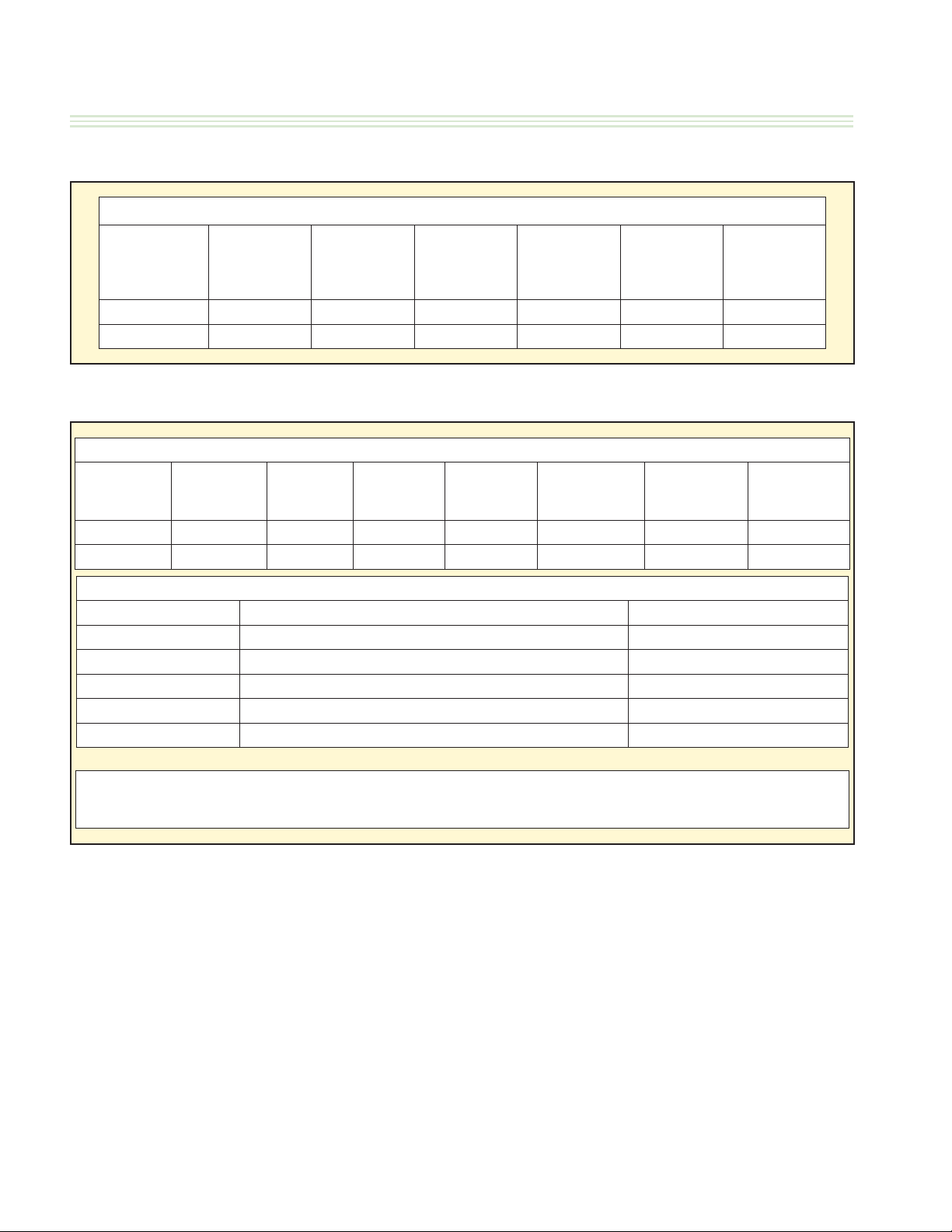
GARLAND CLAMSHELL GRILL START – UP FORM
ELECTRIC OR COMBINATION GAS / ELECTRIC
McDonald’s ___________ Certification ID # __________ Store # _____________ Model
Address ____________________________ City ___________________________
State / Province _____________ Zip Code _________ Serial# _________________________________ Start Up Date ____________
United States Canada International (List Country) ___________________ Telephone # _______________________
Actual Gas Type ____________
Matches Rating Plate? YES NO
1. To avoid personal injury or prope rty damage,
2. Ensure equipment restraint devices are installed correctly according to local codes (Gas & Electric). Note: part supplied by others.
3. Verify, power cord has a strain relief attached fro m power supply cord to grill unit.
4. Ensure grill is installed in the p roper type of
5. Ensure flue restrictors are fully opened or removed. Flue Box Supplied by KES
Flue Restrictors located inside exhaust hood
6. Ensure bottom plate is leveled side to side / front to back / diagonally, in location, under hood. Adjust casters to attain level.
7. REMOVE GRILL FROM UNDER THE HOOD. Turn Power Switch ON, controller displays are active, Controller displays “OFF”.
All platen raises automatically?
8. Lower and raise Upper Platen and e nsure movement is smooth and continuous. Grease shafts accordingly with a FOOD GRADE
LUBRICANT.
9. If upper platen elevation requires lo wered to allow for clearance of hood, lower upper limit switch. Refer to Operations &
Installation manual for platen heights.
10. Press the POWER ON button. Controller displays “PREHEAT - AM”, platen lowers. Heat indicator lights are AMBER?
11. Press and hold the AM / PM key and set to PM. This will allow the unit to heat to: Platen-425˚F(217˚C), Grill-350˚F(177˚C) for a
grill with full default settings.
12. Ensure grill enters SOAK mode (15:00 timer), counts down and upper platen auto calibrates while at temperature.
13. Close valve handle and verify the unit tries to ignite three (3) times and then locks out because of Ignition Failure?
14. GAS PRESSURE CHECKS (if applicable):(Note1: CentershouldnotbefillifMWG2W/MWG2W1)(Note2: Center&RightshouldnotbefillifMWG1W/MWG1W1)
Rated Incoming Pressure
Rated Burner Pressure Natural G as
Propane Gas
15. Check micro amp reading on flame sense to ensure operating micro amps ARE NO LESS THAN 0.8 uA on all burners, unless the
grill is equipped with a CE certified ignition module, in which case the minimum is 2.0 uA.
16. Upon Completion of auto calibration, platen raised automatically, and display reads “READY”
If upon completion of auto calibration process, upper platen does not raise, indicate message on controll er.
Check platen level and adjust reed switches. Cycle power and retry.
17. Select menu item “10:1 – CLAM”. Verify set temperature is reached and LED lights turn GREEN.
18. Initiate cook cycle by pushing the GREEN BUTTON. Platen lowers, and timing cycle begins.
19. Ensure the stores pyrometer is accurate and calibrated using the ice bath method.
20. Perform PROBE CALIBRATION.
21. Perform Platen Leveling procedure & Reed Switch Calibration in “LEVEL / REED SW” mode.
22. Ensure grill performs successful Auto Calibration upon completion of reed switch calibration.
23. Lock down all caps. Ensure that the lock nuts do not turn any of the adjuster nuts when tightening.
24. Assist or obtain assistance with store personnel for Beef/Chicken Integrity Testing, testing product 10:1, 4:1, Angus, Grill
Chicken until desired internal product temperatures are met and record cook time (Product cook times chart below).
Problems / Special Circumstances / Damage:
Name: _________________________________________________________ Name: __________________________________________________________________
Service Agency: _________________________________________________
Sub Agent: (If Applicable) _________________________________________
Have you trained store personnel on the
operation of the grill?
Are you a factory certified technician?
Date of Certification
Located on Certification Sticker (TICK ONE)
Gas Type Electric / 3-phase Record Amps Per Line Each Contactor
NOTE1: CENTER(C) PLATEN should not be checked if MWE2W / MWG2W / MWE2S
NOTE2: CENTER(C) & RIGHT(R) PLATEN should not be checked if MWE1W / MWG1W / MWE1S
Natural Gas: 6 – 14” W.C. /
LEFT
10:1 Tested Auto Mode OK
4:1
ANGUS
GRILL CHICKEN
Submitted by: Accepted by:
(MM/DD/YY)
Visit our
White Copy – Factory Yellow Copy – Service Agency Pink Copy – Customer
Actual Input ____________V /______Hz
208 VAC 380 VAC
220 VAC 400 VAC 60 Hz
230 VAC 415 VAC 50 Hz
240 VAC
INSPECTION / OPERATIONAL CHECK
Check for Gas Leaks
Gas Exhaust Hood
Product Cook Times Beef Integrity Product
https://clamshell.garland-group.com for Literature & Documentation
through the entire gas line.
with the proper air draw.
Propane / Butane Gas: 11 – 14” W.C. Actual Incoming _______” W.C.
3.5” W.C. Actual Left ________ Center ________ Right ________
3.5” W.C. for MWG3W/MWG3W-1 Actual Left ________ Center ________ Right _________
10” W.C. for MWG2W/MWG2W-1 MWG1W/MWG1W-1
CENTER
(If Applicable)
YES / NO
YES / NO
complete a startup is approximately 1.5 – 2 hours. Please
keep in mind this estimated time when scheduling the
startup. After hours or overtime is not covered under
warranty and will be billed at a charge which is the
di erence between the Garland Reimbursement rate and
the Factory Authorized Service Centers overtime charges.
A factory startup is necessary to start the warranty period.
The Authorized Service Center is required to complete
the paperwork during the startup process, and send it
to Garland Commercial Ranges for reimbursement. At
the time of receipt, Garland will start the warranty period
which will conclude at the end of 2 years.
( MM / DD / YYYY )
Left
Line 1
Line 2
Line 3
RIGHT
(If Applicable)
Have you been adequately informed of the operation of the grill, its uses and its general
operation? YES | NO – Indicate comments __________________________________
________________________________________________________________________
________________________________________________________________________
________________________________________________________________________
Manual Mode OK
Center
(If Applicable)
PASSED – NO GAS LEAKS
OK
YES / NO
OK
OK
OK
OK
OK | C OK | R OK
L
L
OK | C OK | R OK
L
OK | C OK | R OK
OK | C OK | R OK
L
L
OK | C OK | R OK
OK | C OK | R OK
L
OK | C OK | R OK
L
OK
Micro-amps Reading =
OK -
L / C / R
Check Platen Level -
Check Reed Switch -
OK | C OK | R OK
L
OK | C OK | R OK
L
OK
OK | C OK | R OK
L
OK | C OK | R OK
L
OK | C OK | R OK
L
OK | C OK | R OK
L
OK | C OK | R OK
L
Right
(If Applicable)
L / C / R
L / C / R
Page 26
Part #4530667 Rev 4 (30 Jan 15)
Page 27

GARLAND CLAMSHELL GRILLS WITH PRODUCT RECOGNITION INSTALLATION/OPERATION MANUAL-1&2 PLATEN
TEMPERATURE PROBE CALIBRATION
Calibration/Verification of Grill Temperature Zones
HOT SURFACE
Grill Temperatures
Will Cause Severe
Burns
Overview
Reason: To Maintain Accurate Grill Temperature Zones.
Models: 1 and 2 Platen Grills.
Tools: Digital Pyrometer with Surface Probe.
Procedures:
1. Temperature Veri cation Procedure.
2. Temperature Calibration Procedure. (New grill installation, start with temperature calibration)
WARNING:
PERSONAL INJURY FROM BURNS MAY RESULT WHEN COMING IN CONTACT WITH HOT COOKING
SURFACES.
NOTE:
1. CALIBRATION AND VERIFICATION OF GRILL IS DONE WITH RELEASE MATERIAL SHEETS “OFF”.
2. MUST CLEAN GRILL PLATE AND PLATEN SURFACES.
1. Temperature Verification Procedure
PLEASE FOLLOW THESE INSTRUCTIONS EXACTLY AS THEY APPEAR BELOW:
1. The upper platens and lower grill plate
should be at operating temperatures to perform this calibration procedure. Press the
or
button to select a “CLAM” operation
that requires a temp of 350
0F
(1770C) on
the griddle plate and allow the grill to reach
the set temperature and stabilize, (approximately 30 minutes).
2. Press and hold the temperature button for
approximately 3 seconds, or until the controller will display all temperature values
(T,F,M,B).
3. Place pyrometer over the marks on grill
plate indicating thermocouple location (see
sketches on next pages). Allow at least 5
to 10 seconds for the pyrometer to respond
and stabilize.
4. Check calibration for each heat zone when
the following conditions occur:
A. The temperature indicator light for the
specifi c thermocouple is GREEN
B. Temperature read out for a specifi c ther-
mocouple on the control is decreasing.
C. Optimum range for VERIFICATION
is between 355F (180C) and 350F
(177C). This procedure can require up
to 10 minutes, depending on the point in
time the operator gets in the heat cycle.
IMPORTANT NOTE:
For 1 and 2 Platen Electric Slim Grills, the
controller display will show temperature values
for T,F & B. M : will always display word
“Slim”, (see picture on page 29).
5. Temperature delta between pyrometer and
controller must be +/-5F (+/-3C). If the
temperature delta between pyrometer and
controller is more than +/-5F (+/-3C) go to
TEMPERATURE CALIBRATION PROCEDURE
to correct required zone.
continue on next page →
Part #4530667 Rev 4 (30 Jan 15)
Page 27
Page 28

INSTALLATION/OPERATION MANUAL-1&2 PLATEN GARLAND CLAMSHELL GRILLS WITH PRODUCT RECOGNITION
TEMPERATURE PROBE CALIBRATION (continued)
Calibration/Verification of Grill Temperature Zones
2. Temperature Calibration Procedure
PLEASE FOLLOW THESE INSTRUCTIONS EXACTLY AS THEY APPEAR BELOW:
1. The upper platens and lower grill plate
should be at operating temperatures to
perform this calibration procedure. Press the
or button to select a “CLAM” opera-
tion that requires a temp of 350
0
(1770C) on
the griddle plate and allow the grill to reach
the set temperature and stabilize, (approximately 30 minutes).
2. PRESS and HOLD the
button for approximately 3 seconds, or until the controller will
display: “PROBE CAL”
3. PRESS the
button to display the fi rst
temperature zone to be calibrated. The fi rst
zone to be calibrated is “FRONT TEMP CAL”.
The zones are displayed in order of FRONT
TEMP CAL, MIDDLE TEMP CAL, BACK TEMP
CAL, TOP TEMP CAL.
4. Select a heat zone display using the
or
buttons.
5. Place pyrometer over the marks on grill
plate indicating thermocouple location (see
sketches on next pages). Allow at least 5
to 10 seconds for the pyrometer to respond
and stabilize. Note the temperature on the
pyrometer.
IMPORTANT NOTE:
Optimum range for CALIBRATION is between 355F (180C) and 350F (177C). This
procedure can require up to 10 minutes, depending on the point in time the operator gets
in the PROBE CAL.
the displayed temperature in one, (1) degree increments. The
button will decrease the displayed temperature in one,
(1), degree Increments.
NOTE: During step 6, the control should
be sounding a high-pitched tone. The temperature can only be adjusted if this tone
is sounding and display fl ashing. If the
control is silent and display not fl ashing,
the temperature will not change.
7. As soon as you have a temperature match
PRESS the
button to lock the calibrated
temperature into the controller.
Note: If calibration window is missed,
press
to go back to the previous step.
= Exits funtion without any modifi ca-
tion, as long as
button has not been
pressed.
8. Press the
or button to select the next
heat zone.
9. Move the pyrometer’s surface probe to the
newly selected heat zone and repeat steps
5, 6, and 7.
IMPORTANT NOTE:
For 1 and 2 Platen Electric Slim Grills, the
controller display will show temperature values
for T,F & B. M : will always display word
“Slim”, (see picture on page 29).
6. Adjust the temperature on the grill control
accordingly to match the temperature on
the pyrometer. The
Page 28
button will increase
continue on next page
Part #4530667 Rev 4 (30 Jan 15)
→
Page 29

GARLAND CLAMSHELL GRILLS WITH PRODUCT RECOGNITION INSTALLATION/OPERATION MANUAL-1&2 PLATEN
TEMPERATURE PROBE CALIBRATION (continued)
Calibration/Verification of Grill Temperature Zones
2. Temperature Calibration Procedure - continuation
10. Repeat the procedure for each of the heat
zones.
General Defi nition of Thermocouples Usage
11. Exit the program mode by pressing the
button. The controller will return to its
previous state in the Normal Operating
Mode for temperature verifi cation (page 1).
Always conduct verifi cation after each cali-
bration
Grill Models
1 & 2 Platen
Electric and Gas
Grill Models
1 & 2 Platen
Electic Slim
Quantity of
Thermocouples
on Grill
3
Quantity of
Thermocouples
on Grill
2
Controller
Display
B Back
F Front
Controller
Display
B Back
F Front
Thermocouple
Location
on Grill Plate
Thermocouple
Location
on Grill Plate
Quantity of
Thermocouples
on Platen
1 T = Top CenterM Middle
Note: Temperature
reading could be in
Fahrenheit or Celsius
Quantity of
Thermocouples
on Platen
1 T = Top Center
Thermocouple
Location
on Platen
Thermocouple
Location
on Platen
Part #4530667 Rev 4 (30 Jan 15)
Page 29
Page 30

INSTALLATION/OPERATION MANUAL-1&2 PLATEN GARLAND CLAMSHELL GRILLS WITH PRODUCT RECOGNITION
TEMPERATURE PROBE CALIBRATION (continued)
1 & 2 Platen Thermocouple Location of Grill Zones
1 & 2 PLATEN SLIM SIZE
ELECTRIC MODEL ONLY
17.53in
4.25in
[108mm]
36.00
[914mm]
8.766in
[223mm]
[445mm]
PLATEN WIDTH
11.88in
[302mm]
9.00in
[229mm]
1 & 2 PLATEN FULL SIZE
ELECTRIC MODEL ONLY
4.25in
[108mm]
B
F
FRONT
OF GRILL
36.00
[914mm]
9.00in
[108mm]
PLATE
DEPTH
11.875in
[302mm]
T
THERMOCOUPLE LOCATION
BACK OF
GRILL
TOP PLATEN VIEW ALL MODELS
1 & 2 PLATEN FULL SIZE
GAS MODEL ONLY
36.00
PLATE WIDTHPLATE WIDTH
[914mm]
4.25in
108mm
8.33in
216mm
Page 30
19.50in
[495mm]
11.87in
[302mm]
9.00in
[229mm]
B
B
M
M
F
FRONT
OF GRILL
[108mm]
9.00in
PLATE
DEPTH
24in
FRONT OF GRILL
(TOP VIEW)
PLATE DEPTH 24in
9.00in
229mm
F
9.00in
FRONT
OF GRILL
229mm
19.50in
*
495mm
Part #4530667 Rev 4 (30 Jan 15)
Page 31

GARLAND CLAMSHELL GRILLS WITH PRODUCT RECOGNITION INSTALLATION/OPERATION MANUAL-1&2 PLATEN
INSTALLATION OF RELEASE MATERIAL
The following are the procedures for installing the Release Material sheets on the upper platen on the Garland Clamshell
grill. The components shown below are included with your grill when purchased.
CAUTION: UPPER PLATEN IS EXTREMELY HOT.
1. Slide release material rod through hemmed end of the
release material sheet.
HEMMED
LOOP
MATERIAL
ROD
RELEASE
MATERIAL
“Teon Sheet” available from your DC
Saint GobainėDC WRIN # 02174-003
TaconicėDC WRIN # 02174-000
2. Hook release material rod on brackets located at the
rear of the upper platen.
FRONT FLAP
WRAPPED
OVER RELEASE
MATERIAL BAR
AND CLIPPED
IN PLACE
LEFT & RIGHT
FLAPS
5. After securing the release sheet from the back of
the platen to the front, secure it to the left and right
sides of the platen. Wrap one side of the release sheet
material around the side of the platen. Place one (1)
locking clip over the sheet and press into place over
release material bar. Repeat this procedure for the
other side of the platen.
RELEASE
MATERIAL
CLIPS
UPPER PLATEN
(SIDE VIEW)
RELEASE
MATERIAL
MATERIAL
MATERIAL
ROD HOLDER
ROD
3. Holding the bottom of the release material sheet in
place, gently pull the sheet toward the front of the
platen, and wrap the front ap up and over the release
material bar on the front of the platen.
4. Place two (2) locking clips over release material sheet
and press into place over release material bar.
NOTE: Make sure release material is t smoothly along the
bottom surface of the upper platen.
Part #4530667 Rev 4 (30 Jan 15)
WRAP & CLIP BOTH SIDES
5. Check alignment and tightness of release material
against upper platen.
Release material sheets should be replaced when:
• Product sticks to release material
• Carbon build-up causes problems in taste or
appearance.
• A tear in the release material sheet’s cooking area.
• Release material coating is worn o sheet.
NOTE: Rotate the release sheets on daily basis
Page 31
Page 32

INSTALLATION/OPERATION MANUAL-1&2 PLATEN GARLAND CLAMSHELL GRILLS WITH PRODUCT RECOGNITION
INSTALLATION OF SPLASH SHIELD
The following is the procedure for installing the Splash Shield on the rear of the upper platen arm assembly. The Splash
Shield is installed to protect the back splash from grease splashing during normal operating use of the grill.
*TWO PER UPPER PLATEN
STEP 1
UPPER
PLATEN
UPPER PLATEN
BLOCK PIN
(ONE ON EACH SIDE)
SPLASH SHIELD
HOOK FEATURE
STEP 2
SURFACE OF
GRILL PLATE
NOTE: SOME COMPONENTS OMITTED FOR CLARITY
UPPER PLATEN
BLOCK PIN
SPLASH
SHIELD
SPLASH SHIELD
HOOK FEATURE
Page 32
NOTE: SOME COMPONENTS OMITTED FOR CLARITY
SPLASH SHIELD HOOK FEATURE
UP AND ONTO UPPER PLATEN
BLOCK PIN IN THIS DIRECTION
(BOTH SIDES)
Part #4530667 Rev 4 (30 Jan 15)
Page 33

GARLAND CLAMSHELL GRILLS WITH PRODUCT RECOGNITION INSTALLATION/OPERATION MANUAL-1&2 PLATEN
GRILL ACCESSORIES
Te on Wraparound Kit (1&2 platen only)
Description: Te on Sheet (Wraparound)
Part Number: 4527642
Quantity:
3
Description: Te on Wraparound Kit
Part Number: 4528083
Quantity:
1 - (Includes all Shown)
Description: Te on Clip
Part Number: 4527294
Quantity:
Description: Te on Rear Bar
Part Number: 4526436
Quantity:
1
4
Part #4530667 Rev 4 (30 Jan 15)
Page 33
Page 34

INSTALLATION/OPERATION MANUAL-1&2 PLATEN GARLAND CLAMSHELL GRILLS WITH PRODUCT RECOGNITION
GRILL ACCESSORIES
BELOW POWER CORDS ARE RECOMMENDED
ONLY. CORDS APPY TO APPLICATION AND
ARE NOT STANDARD.
Interlock Cord - 5Wire
(No Garland P/N) - *** Not supplied by Garland
NEMA# L15-30P
3Phase4Wire 30Amp Power Cord (Electric Grill Only)
(No Garland Part Number) Not Supplied by Garland.
3Phase4Wire 50Amp Power Cord (Electric Grill Only)
(No Garland Part Number) Not Supplied by Garland.
Quick Disconnect Gas Hose
Teon Sheet (Non Wraparound)
(Item 1591506)
Teon Rear Rod
P/#: 4526436
Teon Sheet
(Non Wraparound)
P/#: 1799301
Teon Clip
P/#: 4527294
Page 34
Part #4530667 Rev 4 (30 Jan 15)
Page 35

GARLAND CLAMSHELL GRILLS WITH PRODUCT RECOGNITION INSTALLATION/OPERATION MANUAL-1&2 PLATEN
CLEANING & MAINTENANCE
Warning: Pinch Hazard keep hands and tools clear when platens are in motion. Unexpected movement of platens can occur during cleaning
or servicing process. Turn Grill O at main switch when cleaning platen
McD
®
Hi-Temp Grill Cleaner
Nettoyant à chaud
pour grils
Limpiador de parrillas
de alta temperatura
CAUTION: May cause eye and skin
irritation. See precautionary and
KEEP OUT OF REACH OF CHILDREN
CUIDADO: Puede causar irritación
de los ojos y la piel. Véanse
las precauciones y los primeros
auxilios al reverso.
MANTENGASE FUERA DEL
ALCANCE DE LOS NIÑOS
AVIS : Peut irriter les yeux et la peau.
Voir précautions et premiers
soins au verso.
CONSERVER HORS DE LA
PORTÉE DES ENFANTS
®
3.6 oz (106 ml)
McD
®
Hi-Temp
Grill Cleaner
KAY® Grill Cleaning Pad Holder
®
Grill Cleaning Pad
& KAY
Heat-Resistant Gloves Clean, Sanitizer-Soaked
Grill Cloths
Lid
Grill Squeegee
Grill Scraper
1
2
3
Warning
• Select Clean Mode.
Once Clean Mode has
AUTO
AM
MAN
PM
P
been reached turn
each zone OFF.
• Turn Main Switch OFF
when cleaning platens
• Following Step has to be
performed by using a
Grill Scraper approved by
McDonald’s.
• Failure to use a
McDonalds approved
scraper may result in grill
surface damage.
• Note: Never use a steel
Grill Scraper
scraper to clean the
upper platens.
• Scrape the lower grill
• Wipe the Release
Material® sheets with a
clean, sanitizer-soaked
grill cloth.
surface with the grill
scraper.
• Use grill squeegee to
push residual grease into
trough.
• Take grill scraper to the
• Remove the locking
5
3-compartment sink to
be washed and rinsed.
clips, bars, and release
sheets.
• Take the clips and bars to
the 3-compartment sink
to be washed and rinsed;
set aside.
• Empty and replace the
grease troughs.
• Set release sheets aside
on a at surface.
4
Part #4530667 Rev 4 (30 Jan 15)
• If splash guards are
installed, detach
and take to the
3-compartment sink to
be washed and rinsed;
set aside.
6
LA
ANTS
la peau.
3.6 oz (106 ml)
DES ENF
meros
ions et premiers
i
les yeux et
UERA DEL
r
F
PORTÉE
soins au verso.
DE LOS NIÑOS
CONSERVER HORS DE
in
y los p
k
y and
F CHILDREN
a
s
oir précaut
ar
Peut irriter
V
:
H O
ALCANCE
ye and s
auxilios al reverso.
MANTENGASE
VIS
A
Puede causar irritación
ecaution
r
p
las precauciones
de los ojos y la piel. Véanse
UT OF REAC
O
May cause e
CUIDADO:
ON:
KEEP
I
irritation. See
®
CAUT
pour grils
de alta temperatur
McD
Limpiador de parrilla
emp Grill Cleaner
Nettoyant à chaud
Hi-T
7
• Open one packet of McD
Hi-Temp Grill Cleaner
and empty the contents
into a lid or stainless
steel pan.
• Put on the heat-resistant
gloves and safety
glasses.
Page 35
Page 36

INSTALLATION/OPERATION MANUAL-1&2 PLATEN GARLAND CLAMSHELL GRILLS WITH PRODUCT RECOGNITION
CLEANING & MAINTENANCE (continued)
• Dip the KAY Grill
Cleaning Pad Holder into
the grill cleaner.
• Note: Never use a steel
scraper to clean the
upper platens
8
• Apply McD Hi-Temp
Grill Cleaner to front
side of platens starting
from right platen to left
platen.
• DO NOT SCRUB
9
• Apply the grill cleaner to
platen surfaces starting
from right platen to left
platen.
• DO NOT SCRUB
13
14
• (This step not required
on one platen version)
• Turn Main Switch ON.
• Press green button to
lower right platen.
• Turn Main Switch OFF.
• (This step not required
on one platen version)
• Apply grill cleaner to
inner edges of the right
and left platens.
• DO NOT SCRUB
• Turn Main Switch ON.
• Press green button to
raise right platen.
• Turn Main Switch OFF.
• Pour remaining McD HiTemp Grill Cleaner over
bottom grill surface.
10
11
12
• Apply the grill cleaner
to back side of platens
from right platen to left
platen.
• DO NOT SCRUB
• Apply the grill cleaner to
outer edges of right and
left platens.
• DO NOT SCRUB
15
• Spread the cleaner over
the entire lower grill
surface from front to
back using even strokes.
• DO NOT SCRUB
16
• Start scrubing now.
• Scrub front side of
platens from right platen
to left platen with KAY
Grill Cleaning Pad Holder
and Pad.
17
Page 36
Part #4530667 Rev 4 (30 Jan 15)
Page 37

GARLAND CLAMSHELL GRILLS WITH PRODUCT RECOGNITION INSTALLATION/OPERATION MANUAL-1&2 PLATEN
CLEANING & MAINTENANCE (continued)
18
19
20
• Scrub at grill surfaces
starting from right platen
to left platen.
• Scrub back side of
platens from right platen
to left platen.
• Scrub outer edges of
right and left platens.
• Turn Main Switch ON
23
24
25
• Turn Main Switch OFF
• Scrub lower grill surface.
• Rinse front, side and
back of platen surfaces
with a clean, sanitizersoaked grill cloth,
starting from right to left
platens.
• Turn Main Switch ON
• (This step not required
on one platen version)
• Press the green button
to lower right platen.
• Turn Main Switch OFF.
• Rinse inner edges of
both platens.
• Turn Main Switch ON.
• Press green button to
raise the platen.
21
22
Part #4530667 Rev 4 (30 Jan 15)
• (This step not required
on one platen version)
• Press green button to
lower right platen.
• Turn Main Switch OFF
• (This step not required
on one platen version)
• Turn Main Switch OFF.
• Scrub inner edges of the
right and left platens.
• Turn Main Switch ON.
• Press green button to
raise the right platen.
• Turn Main Switch OFF.
• Wipe back of lower grill
with a clean, sanitizersoaked grill cloth.
26
• Pour a small amount of
lukewarm water on a
clean, sanitizer-soaked
grill cloth over the
bottom grill surface and
wipe o residue.
27
Page 37
Page 38

INSTALLATION/OPERATION MANUAL-1&2 PLATEN GARLAND CLAMSHELL GRILLS WITH PRODUCT RECOGNITION
CLEANING & MAINTENANCE (continued)
• Place upper platen
Release Material sheets
28
29
at on grill surface.
• Gently clean both sides
of the Release Material
sheets with the KAY Grill
Cleaning Pad Holder.
31
• Rinse both sides of the
Release Materialsheets
with a clean, sanitizersoaked grill cloth.
• Reinstall upper Release
Material sheets; secure in
place with bars and clips.
32
• Empty, wash, rinse,
and replace the grease
troughs.
• Wipe remaining grill
surfaces with a clean,
sanitizer-soakedgrill
cloth.
• Wipe lower grill with a
clean,sanitizer-soaked
grill cloth. Repeat until
no visible soil remains.
30
PUSH / PULL GRILL PROCEDURE
1. Turn main switch ON.
2. Press green button to lower platen(s).
3. Turn main switch OFF.
4. Unplug power cord and proceed with
pull/push.
WARNING,
Avoiding procedure may cause
damage or loss of calibration on
the platen and potential of error
message can occur.
• Apply a thin coat of fresh
shortening to the lower
grill surface only.
33
Page 38
PASS – Gently pull or push
FAIL – Potential to damage
platen adjustment
Part #4530667 Rev 4 (30 Jan 15)
Page 39

GARLAND CLAMSHELL GRILLS WITH PRODUCT RECOGNITION INSTALLATION/OPERATION MANUAL-1&2 PLATEN
Key D – Automatic/Manual
Key D will be used to select between Automatic and Manual cooking. Used for product recognition
only.
g
y
Will work in sequence with the other middle and front grill Heater LED’s. IF the temperature is below
set point the LED will be orange, if the temperature is between the set point and 79F LED will be
green, if the temperature is set point plus 80F or higher the LED will be red.
DESCRIPTION OF GRILL CONTROL
A
H L
TM
Garland
BACK GRILL
MEDIUM GRILL
FRONT GRILL
AUTO
AM
B
Items Key Data Funtions
Key A – Standby Key A will be used to put the control into the Standby mode.
A
Key B – On/O Key B will turn the control on and o. PRESSING and HOLDING button for 2 seconds
B
Key C – AM/PM
C
D
Key E – Programmin
E
Key F – Temperature
F
Key G - Time
G
Key H – Up Arrow Key H will scroll up through the menus as well as scroll up in the programming mode.
H
Key I – Down Arrow Key F will scroll Downs through menus as well as decrement values in the programming mode.
I
Key J – Left Arrow Key J will be used for scrolling through menus and well as in programming.
J
Key K – Right Arrow Key K will be used for scrolling through menus and well as in programming.
K
Key L – Enter Function
L
(Menu
Select)
AM
MAN
PM
PM
D
C
This button is used to toggle back and forth between the AM menu list and the PM menu list in
manual cook mode. In automatic mode this button will toggle between the AM product
recognition gaps and the PM product recognition gaps.
Key E will allow the user to enter and exit the Programming Mode. PRESSING & HOLDING button for 3 seconds
F will be used to view the set point and actual temperature of the grill and platen.
Ke
Key G will be used to change the remove time of a specic menu item and to calibrate the grill
Key L will be used to enter new values that have been changed in the programming modes.
J
K
I
P
E
PLATEN
PLATEN
F G
LED Description
Platen
Back Grill
Middle Grill
Front Grill
Part #4530667 Rev 4 (30 Jan 15)
IF the temperature is below set point the LED will be orange, if the temperature is between the set
point and 79F LED will be green, if the temperature is set point plus 80F or higher the LED will be red
Will work in sequence with the other middle and front grill Heater LED’s. IF the temperature is below
set point the LED will be orange, if the temperature is between the set point and 79F LED will be
green, if the temperature is set point plus 80F or higher the LED will be red.
Will work in sequence with the other middle and front grill Heater LED’s. IF the temperature is below
set point the LED will be orange, if the temperature is between the set point and 79F LED will be
green, if the temperature is set point plus 80F or higher the LED will be red.
Page 39
Page 40

INSTALLATION/OPERATION MANUAL-1&2 PLATEN GARLAND CLAMSHELL GRILLS WITH PRODUCT RECOGNITION
ERROR MESSAGING
• Error messages were improved in this latest product release and have now actionable items.
• An error log feature will help technicians with up to 51 di erent error codes in the troubleshooting process.
• A maximum of 99 error instances can be saved in a non-volatile memory so the information can be read
regardless the unit has been powered OFF.
• All new diagnostic features and error information is detailed in service manual.
• Results from latest successful calibration are saved in the Calibration Log under the Service Menu.
• Some examples of more commom errors and actions are as follows:
Error
Code#
Several ERROR Refer to Service Manual 1
21 OBSTRUCTION Check for object under platen that could jam platen 1
34 ROOM TEMP LOW Raise room temperature above 32 degrees F / 0 degrees C 2
35 ROOM TEMP HIGH Lower room temperature to below 176 degrees F / 80 degrees C 2
36 NO IGNITION
Several GRILL TOO HOT Temperature high - Allow cool down 1
48 PROD. NOT RECOG Check object on the grill - Clean grill 1
54 WRONG GRILL TYPE Gas grill set to electric or viceversa - correct setting 2
Message on Screen Possible Meaning Action
Check gas gauge supply for gas models or electric power for
electic models
2
Action to take :
1. Press Green button to recalibrate grill and see if error repeats. if error persist call for service near you area.
2. Turn main switch o and on.
OPERATION PROCEDURES
General Overview:
The grill controller will allow for 2 functions, both
described in detail in the following sections
The “Normal Operating Mode”, also known as the Cook
Mode is the mode used during normal cooking. In the
normal operating mode, the operator can start a cook
cycle, cancel a cook cycle, view actual temperatures, scroll
to another menu item, and enter the Programming Mode.
The “Programming Mode” is the mode in which the
operator can program the controller’s various settings. To
enter the programming mode, PRESS and HOLD
There are currently 3 methods of cooking that can be
utilized with the 1 & 2 platen Garland clamshell:
Manual Mode Cooking – This is the cook method that
utilizes a single gap setting for each menu item. The timer
will count down according to the selected menu item.
Page 40
Multi Stage Cooking – This method of cooking utilizes 2
di erent gap settings during the cook cycle. The timer will
count down according to the selected menu item.
Automatic Mode Cooking (Product Recognition) – The
Product Recognition (PR) method of cooking uses the
magnetic switches mounted on the upper platen arm
assembly to determine the product being cooked. Using
the PR feature, the operator simply selects the button
on the controller. Select Automatic Mode; press and
hold button. This will allow the controller to know
what product group to select from. When a cook cycle is
initiated, the platen will come down and recognize the
product being cooked. The cook timer will count down
according to the time set for the recognized item. For more
information on product Recognition, see the next section;
“Product Recognition.”
Part #4530667 Rev 4 (30 Jan 15)
Page 41

GARLAND CLAMSHELL GRILLS WITH PRODUCT RECOGNITION INSTALLATION/OPERATION MANUAL-1&2 PLATEN
OPERATION PROCEDURES (continued)
To turn the grill on:
The Main Power Switch – Controls power to the grill
and must be turned ON to start operation. The controller
displays will be active. Upon successful power up checks,
the controllers will displays “OFF”.
AM Operation – Release Material sheets MUST be ON at
this time and the grill surface should be free and clear of
carbon.
Once the PRC displays “OFF” press . The PRC will go to
PREHEAT mode and default to AM preheat temperatures.
To preheat to PM temperatures, press and hold .
AM PREHEAT PM PREHEAT
375˚F(190˚C)Upper Platen 425˚F (218˚C) Upper Platen
275˚F (135˚C) Grill 350˚F (177˚C) Grill
Upon reaching the AM or PM set temperature (whichever
is selected), the grill will stabilize in temperature for fteen
(15) minutes. Once this time has elapsed, the grill will
autocalibrate. Upon completion of autocalibration, the
upper platens will raise to there normal position, and the
PRC will display “READY”.
To Select a Menu item:
Scroll forward through the list of available menu items by
pressing repeatedly. Scroll backward through the list of
available menu items by pressing repeatedly.
Menu Item Library
The menu item library is loaded in the computer based
upon the setting programmed in [CONFIGURE]->[GRILL
REGION]. Each menu item consists of a function called
[DISPLAY ACTIVE]. The settings in this function (AM, PM,
AM/PM, No) determine what menu items are displayed
when the button is pressed.
Menu Item
10:1 - CLAM PM
4:1 - CLAM PM
STRIP BACON - CLAM AM/PM
SAUSAGE CLAM FZN AM
MCRIB - CLAM NO
STEAK - CLAM AM/PM
GRILLED CHICKEN - FLAT PM
FOLDED EGGS FLAT AM
ROUND EGGS - FLAT AM
CHICKEN FLAT BRD - FLAT NO
10:1 FLAT NO
4:1 - FLAT NO
Display Active –
Default
MCRIB - FLAT NO
SAUSAGE FLAT FZN NO
HOTCAKES - FLAT NO
FOLDED EGGS CLAM AM
ROUND EGGS CLAM AM
3:1 ANGUS CLAM PM
MUSHROOMS CLAM AM/PM
OPT MENU 5 - CLAM NO
OPT MENU 6 - CLAM NO
OPT MENU 7 - CLAM NO
OPT MENU 1 - FLAT NO
OPT MENU 2 - FLAT NO
OPT MENU 3 - FLAT NO
OPT MENU 4 - FLAT NO
Indicator Lights
The LED lights on the main control indicate the
temperature status of each zone.
Electric grills have (4) zones per section , TOP, (platen),
BACK GRILL, MIDDLE GRILL, and FRONT GRILL.
Gas grills have (2) zones per section , TOP, (platen),
and GRILL.
RED – The zone(s) is “TOO HOT” (more than 79˚F/43˚C over
set temperature) OR a heat zone failure has occurred.
AMBER – The zone(s) is calling for heat.
GREEN – The zone(s) is at or above set temperature, but
below 79˚F/43˚C over set temperature.
Standby Mode
To enter the standby mode:
1. Press the button. The upper platen will lower, and
the grill will maintain a set temperature of Upper platen
- 425˚ F (218˚C), Grill Surface - 350˚ F (177˚C).
To Exit the standby Mode:
1. Press the GREEN or ( GREEN & BLACK) pushbutton(s). The upper platen will raise.
To display the current temperatures:
1. Press the button and repeat for each zone to be
displayed:
1st key press – Front Set Point
2nd key press – Front Actual
3rd key press – Mid Set Point
4th key press – Mid Actual
5th key press – Back Set Point
6th key press – Back Actual
7th key press – Platen Set Point
8th key press – Platen Actual
Part #4530667 Rev 4 (30 Jan 15)
Page 41
Page 42

INSTALLATION/OPERATION MANUAL-1&2 PLATEN GARLAND CLAMSHELL GRILLS WITH PRODUCT RECOGNITION
OPERATION PROCEDURES (continued)
2. Pressing and holding the
will displway all of the current temperatures at once.
button for ve (3) seconds
Breakfast In Auto mode
1. Select AM mode. Press and hold the button.
Breakfast In Manual mode
1. Select AM mode. Press and hold the button.
2. Select Manual mode. Press and hold the the button.
3. Select a product from the AM product library using the
or arrow buttons.
4. Following McDonalds procedures for the item selected,
load product on the grill.
5. Press the GREEN or ( GREEN & BLACK) pushbutton(s) to initiate a cook cycle.
6. Alarm will sound when the cook cycle is complete.
7. Remove product and clean grill to prepare for the next
cook cycle.
Lunch In Manual mode
Note: Switching from breakfast to lunch menu items will
take approximately 10 minutes to heat to the appropriate
temperatures.
1. Select PM mode. Press and hold the button.
2. Select Manual mode. Press and hold the button.
3. Select a product from the PM product library using the
or arrow buttons.
4. Following the below lay pattern, load product on the
grill.
5. Press the GREEN or ( GREEN & BLACK) pushbutton(s) to initiate a cook cycle.
6. Alarm will sound when the cook cycle is complete
7. Remove product and clean grill to prepare for next cook
cycle.
To Change The Cook Time for a Menu Item
1. Select AM or PM mode. Press and hold the button.
2. Select Manual mode. Press and hold the button.
3. Select a product using the or arrow buttons.
4. PRESS the button to display the cook time.
5. Use the and buttons to change the cook time.
6. The control will automatically default back to the
normal operating mode after 3 seconds.
Page 42
2. Select Auto mode. Press and hold the
control will display “AM / AUTOMATIC”
3. Following McDonalds procedures for the item selected,
load product on the grill.
4. Press the GREEN or ( GREEN & BLACK) pushbutton(s) to initiate a cook cycle. The platen will lower,
and recognize the product that has been loaded on the grill.
5. Alarm will sound when the cook cycle is complete.
6. Remove product and clean grill to prepare for the next
cook cycle.
button. The
Lunch In Auto mode
Note: Switching from breakfast to lunch menu items will
take approximately 10 minutes to heat to the appropriate
temperatures.
1. Select PM mode. Press and hold the button.
2. Select Auto mode. Press and hold the button. The
control will display “PM / AUTOMATIC.”
3. Following the lay patterns shown on the following page,
load product on the grill.
4. Press the GREEN or ( GREEN & BLACK) pushbutton(s) to initiate a cook cycle. The platen will lower,
and recognize the product that has been loaded on the grill.
5. Alarm will sound when the cook cycle is complete
6. Remove product and clean grill to prepare for next cook
cycle.
Transition Cooking
Approximately 30 minutes before changing to the lunch
menu, perform the following:
1. PRESS the
temperature).
2. Press the button.
3. The upper platen indicator will turn on. The upper
platen will heat to 425 degrees F (217 degrees C) the
platen will maintain this set temperature unless another
menu item is selected.
button (to display the upper platen
To Shutdown Grill
Turn Main Power Switch OFF to disable all burners. For
extended periods of shutdown, turn Main Power Switch
OFF, close and disconnect main gas and/or electrical
connections.
Part #4530667 Rev 4 (30 Jan 15)
Page 43

GARLAND CLAMSHELL GRILLS WITH PRODUCT RECOGNITION INSTALLATION/OPERATION MANUAL-1&2 PLATEN
PRODUCT RECOGNITION
This Garland Clamshell grill is equipped with Product Recognition Controls (PRC) for McDonald’s speci ed select products
only. This new technology allows the user to simply start a cook cycle WITHOUT having to select a speci c menu item.
The PRC will recognize the product thickness by utilizing switches inside the upper platen and the magnets mounted on
the platen arms. Once the PRC calculates the thickness of the product that’s been loaded, it will look up product from the
product range library (below), and automatically select that product. (The minimum and maximum values for applicable
prodcuct are noted in the Factory Default Setting section near the end of this document.)
While cooking in Automatic Mode, the platen will lower and rest on the top of the product. The platen arms will continue
to move in a downward motion performing various calculations to measure the thickness of the product that has been
placed. In the event “Product Not Recognized” or the wrong product is recognized, perform a Auto Forced Calibration.
Performing an Auto Force Calibration will reset the platen to the grill surface.
TO PERFORM AUTO FORCED CALIBRATION
1. PRESS and HOLD the and buttons together. The control will display “AUTO GAP FORCE - NO”.
2. PRESS the button. The “NO” will begin to ash.
3. PRESS the button. The ashing “NO” will change to ashing “YES”.
4. PRESS the button. The upper platen will immediately begin to lower and perform an auto calibration routine.
Part #4530667 Rev 4 (30 Jan 15)
Page 43
Page 44

INSTALLATION/OPERATION MANUAL-1&2 PLATEN GARLAND CLAMSHELL GRILLS WITH PRODUCT RECOGNITION
COMMON PRODUCT RECOGNITION ISSUES
Product Recognition Errors can appear in 2 ways:
1. After initiating cook cycle, the controller displays “PRODUCT NOT RECOGNIZED - NO RECIPE FOUND”.
2. The controller displays the incorrect product for the product that was layed on the grill.
In both cases, the most common reasons for these 2 issues are as follows:
Overlapping Product
OVERLAPPING
PRODUCT
- Ensure that you do
not have any patties
overlapping when you lay
product. This will fool the
controller into thinking
that there is much thicker
product on the grill than
there is
Platen makes contact
with Chicken Ring -
Always make sure that the
chicken ring is clear of the
adjacent platen prior to
initiating a cook cycle.
Wrinkled or Worn Te on
Sheet - Ensure that the
te on sheet is installed
and/or wrapped correctly
to platen. A loose, worn,
or te on sheet with
tears and/or scratches
can e ect product
recognition.
Auto calibation done
with carbon build up or
product residue on grill
surface - Ensure that the
grill surface is free of any
carbon build up. Debris
on the grill surface during
auto calbration will cause
the control to mark
the location of the grill
surface incorrectly.
In any of the cases as outlined above or in any other event, perform an Forced Auto Calibration to reset the upper platen
distance to the grill surface. Prior to performing a Forced Auto Calibration, be sure to:
1. Make sure the upper platen is free and clear of any carbon build up or debris.
2. Ensure that the grill surface is scraped and cleaned.
3. Te on sheet should not be worn and be t to the upper platen tightly.
Perform a Forced Auto Calibration routine as indicated in section “PRODUCT RECOGNITION”, “TO PERFORM FORCED AUTO
CALIBRATION”.
PATTY PLACEMENT
This procedure for placement of meat products on the clamshell grill must be followed exactly. Place patties on the lower
grill plate 2 at a time, from front-to-back, and right-to-left, positioned as shown in the diagrams below. (Each square
represents one cooking lane; the area beneath one upper platen.)
When cooking is complete, the upper platen will raise automatically. Immediately after the platen raises, season the
meat, (if applicable), then remove the patties in the same order they were loaded one at a time. It is important that the
unload sequence is identical to the load sequence.
3
2
222
1
1
1
1
1
1
3
222
2
11
3
11
3
3
2
2
4
1
3
3
2
4
4
2
111
10:1 ONLY
NOTE: Patty placement procedure may vary outside of North America. Please consult your local McDonald’s management.
Page 44
Part #4530667 Rev 4 (30 Jan 15)
Page 45

GARLAND CLAMSHELL GRILLS WITH PRODUCT RECOGNITION INSTALLATION/OPERATION MANUAL-1&2 PLATEN
BEEF INTEGRITY
As shown in the previous page, lay product on the grill in
the manner re ected. Product internal temperatures are
taken on the corner patties.
KEY NOTES:
• Full runs are always required when performing food
safety
• Target removal times are 22 seconds for 10:1’s & 15
seconds for 4:1’s.
• Seasoning the patties must be done prior to
removing the product from the grill.
Cooking grilled chicken utilizes various functions
and settings within the controller to ensure proper
temperature and integrity.
10:1 Patties - Remove in 2 stacks of 4; Probe in center
of corner patties (1, 3, 7, 8).
Step 1: Using a store
calibrated pyrometer,
probe the #1 patty (front
3
3
3
3
right corner) in the center
of the patty.
Step 2: Using a store
calibrated pyrometer,
probe the #3 patty (rear
right corner) in the center
of the patty.
Step 3: Using a store
calibrated pyrometer,
probe the #7 patty (front
left corner) in the center
of the patty.
Step 4: Using a store
calibrated pyrometer,
probe the #8 patty (left
rear corner) in the center
of the patty.
4:1 Patties - Remove in 3 stacks of 2; Probe in center of
corner patties (1, 2, 5, 6).
Step 1: Using a store
calibrated pyrometer,
probe the #1 patty (front
5
3
1
right corner) in the center
of the patty.
The use of a “Too Cool Flag” is programmed under Menu
Item programming. The Too Cool Flag should be set
to “ON” in Grilled Chicken & Mushrooms ONLY. In all
remaining menu items, the “TOO COOL FLAG” should be
turned o .
The “Too Cool Flag” is a function in the control that allows
the grill operator to continue to cook approximately 1
additional run of product should the grill be in a “TOO
COOL” state prior to the start of a cook cycle, or at the end
of a cook cycle
Part #4530667 Rev 4 (30 Jan 15)
Step 2: Using a store
calibrated pyrometer,
probe the #2 patty (rear
5
3
5
3
5
3
1
1
1
right corner) in the center
of the patty.
Step 3: Using a store
calibrated pyrometer,
probe the #5 patty (front
left corner) in the center
of the patty.
Step 4: Using a store
calibrated pyrometer,
probe the #6 patty (left
rear corner) in the center
of the patty.
Page 45
Page 46

INSTALLATION/OPERATION MANUAL-1&2 PLATEN GARLAND CLAMSHELL GRILLS WITH PRODUCT RECOGNITION
PROGRAM LOGIC TREE; PRODUCT MENUS
Press & Hold
(3 seconds)
Menu
Item Displayed
RIGHT or LEFT arrow buttons
Scroll Menu Items
Scroll
Forward
Product
Library
Select Menu Item
Scroll
Backward
CLAM MENU ITEMS FLAT MENU ITEMS
Product Product
Display Active
Grill Set Point
Platen Set Point
Instant On Time
Remove In Time
Multi Stage 1 Time
Multi Stage 2 Time
Multi Stage 3 Time
Remove Alarm
Gap Setting
Display Active
Grill Set Point
Platen Set Point
Instant On Time
Remove In Time
Remove Alarm
Flip Time
Flip Alarm
Sear Time
Sear Alarm
Page 46
Gap Mul/PR Start
Gap Multi Stage 1
Gap Multi Stage 2
Gap Multi Stage 3
Must Remove Time
Toast Buns Time
Toast Buns Alarm
Too Cool Flag
Scroll
Backward
Must Remove Time
Toast Buns Time
Toast Buns Alarm
Too Cool Flag
Scroll
Backward
Part #4530667 Rev 4 (30 Jan 15)
Page 47

GARLAND CLAMSHELL GRILLS WITH PRODUCT RECOGNITION INSTALLATION/OPERATION MANUAL-1&2 PLATEN
CONTROL PROGRAMMING; PRODUCT MENUS
Programming Modes; Product Menu
To change the name of an existing menu
item
1. Using the or button, select the menu item that
requires a name change.
2. PRESS and HOLD the button for approximately 3
seconds. Controller will display previously selected
menu item and its corresponding item number.
3. PRESS and HOLD the button.
4. To spell out the product name:
a. Use the or arrow buttons to scroll through
the character library.
Character Library:
space ! “ # $ % & ‘ ( ) * + , - . / 0 1 2 3 4 5 6 7 8 9 : ; < = > ? @ A B C D E F G
H I J K L M N O P Q R S T U V W X Y Z [ \ ] ^ _ ` a b c d e f g h i j k l m n
o p q r s t u v w x y z
b. PRESS or to scroll right or left.
c. PRESS the button to save the new menu item
name.
5. PRESS the 2X to exit and return to normal operating
mode.
To activate / deactivate a menu item in the
Normal Operating mode library, or change
its day-part
(Defaults are listed in section “OPERATING PROCEDURES”)
1. PRESS and HOLD the button for approximately 3
seconds. Controller will display previously selected
menu item and its corresponding item number.
2. Using the or arrow buttons, select the menu item
that requires activation / deactivation.
3. PRESS the button. The controller will display
“Product”. The menu item will ash.
4. PRESS the or arrow buttons until “Display Active”
is displayed on the controller.
5. PRESS the button. The current setting will ash.
6. PRESS the or button to select a di erent setting.
7. PRESS the button to save the new setting.
8. PRESS the 2X to exit and return to normal operating
mode.
To change the grill surface set point
temperature
NOTE: Grill temperature set points are preset in the controller to the
currently region required standard. Before any adjustment to the grill
set point temperature consult McDonald’s management o ce on your
region. Garland grill set point temperature default on page 55
1. Using the or arrow buttons, select the menu item
that requires a temperature change.
2. PRESS and HOLD the button for approximately 3
seconds. Controller will display previously selected
menu item and its corresponding item number.
3. PRESS the
“Product”.
4. PRESS the or arrow buttons until “Grill SetPt” is
displayed on the controller.
5. PRESS the button. The current grill set temperature
will begin to ash.
6. Using the or button, change the temperature set
point to the new desired temperature.
7. PRESS the button to save the new temperature set
point.
8. PRESS the 2X to exit and return to normal operating
mode.
button. The controller will display
To change the grill upper platen set point
temperature
NOTE: Grill temperature set points are preset in the controller to the
currently required standard. You should not change this set point to any
temperature other than what is shown in section “OPERATING
PROCEDURES”.
1. Using the or button, select the menu item that
requires a temperature change.
2. PRESS and HOLD the button for approximately 3
seconds. Controller will display previously selected
menu item and its corresponding item number.
3. PRESS the button. The controller will display
“Product”.
4. PRESS the or button until “Platen SetPt” is
displayed on the controller.
5. PRESS the button. The “PLATEN SET POINT” will
begin to ash.
6. Using the or button, change the temperature set
point to the new desired temperature.
7. PRESS the button to save the new temperature.
8. PRESS the 2X to return to normal operating mode.
To Change the INSTANT ON TIME
1. Using the or button, select the menu item that
requires a cook time change.
2. PRESS and HOLD the button for approximately 3
seconds. Controller will display previously selected
menu item and its corresponding item number.
Part #4530667 Rev 4 (30 Jan 15)
Page 47
Page 48

INSTALLATION/OPERATION MANUAL-1&2 PLATEN GARLAND CLAMSHELL GRILLS WITH PRODUCT RECOGNITION
CONTROL PROGRAMMING; PRODUCT MENUS (continued)
3. PRESS the button. The controller will display
“Product”.
4. PRESS the or button until “INSTANT ON TIME” is
displayed on the controller.
5. PRESS the button. The seconds will begin to ash.
6. Using the or arrow buttons to change the
INSTANT ON TIME to the new desired time.
7. PRESS the button to save the new time.
8. PRESS the 2X to return to normal operating mode.
To Change the REMOVE IN TIME
1. Using the or button, select the menu item that
requires a cook time change.
2. PRESS and HOLD the button for approximately 3
seconds. Controller will display previously selected
menu item and its corresponding item number.
3. PRESS the button. The controller will display
“Product”.
4. PRESS the or button until “REMOVE IN TIME” is
displayed on the controller.
5. PRESS the button. The seconds will begin to ash.
6. Using the or arrow buttons to change the
REMOVE IN TIME to the new desired time.
7. PRESS the button to save the new time.
8. PRESS the 2X to return to normal operating mode.
To Change the MULTI STAGE TIME
1. Using the or button, select the menu item that
requires a cook time change.
2. PRESS and HOLD the button for approximately 3
seconds. Controller will display previously selected
menu item and its corresponding item number.
3. PRESS the button. The controller will display
“Product”.
4. PRESS the or button until “MULT STAGE(1,2 or3)
TIME” is displayed on the controller.
5. PRESS the button. The seconds will begin to ash.
6. Using the or arrow buttons to change the MULT
STAGE TIME to the new desired time.
7. PRESS the button to save the new time.
8. PRESS the 2X to return to normal operating mode.
To Change the REMOVE ALARM
1. Using the or button, select the menu item that
requires a cook time change.
2. PRESS and HOLD the button for approximately 3
seconds. Controller will display previously selected
menu item and its corresponding item number.
3. PRESS the button. The controller will display
“Product”.
4. PRESS the or button until “REMOVE ALARM” is
displayed on the controller.
5. PRESS the button. The seconds will begin to ash.
6. Using the or arrow buttons to change the
REMOVE ALARM to the new desired option.
7. PRESS the button to save the new time.
8. PRESS the 2X to return to normal operating mode.
To Change the GAP SETTING
1. Using the or button, select the menu item that
requires a cook time change.
2. PRESS and HOLD the button for approximately 3
seconds. Controller will display previously selected
menu item and its corresponding item number.
3. PRESS the button. The controller will display
“Product”.
4. PRESS the or button until “GAP SETTING” is
displayed on the controller.
5. PRESS the button. The seconds will begin to ash.
6. Using the or arrow buttons to change the GAP
SETTING to the new desired setting.
7. PRESS the button to save the new time.
8. PRESS the 2X to return to normal operating mode.
To Change the GAP MUL/PR START
1. Using the or button, select the menu item that
requires a cook time change.
2. PRESS and HOLD the button for approximately 3
seconds. Controller will display previously selected
menu item and its corresponding item number.
3. PRESS the button. The controller will display
“Product”.
4. PRESS the or button until “GAP MUL/PR START” is
displayed on the controller.
5. PRESS the button. The seconds will begin to ash.
6. Using the or arrow buttons to change the GAP
MUL/START to the new desired setting.
7. PRESS the button to save the new time.
8. PRESS the 2X to return to normal operating mode.
Page 48
Part #4530667 Rev 4 (30 Jan 15)
Page 49

GARLAND CLAMSHELL GRILLS WITH PRODUCT RECOGNITION INSTALLATION/OPERATION MANUAL-1&2 PLATEN
CONTROL PROGRAMMING; PRODUCT MENUS (continued)
To Change the GAP MULTI STAGE (1,2 or3)
1. Using the or button, select the menu item that
requires a cook time change.
2. PRESS and HOLD the button for approximately 3
seconds. Controller will display previously selected
menu item and its corresponding item number.
3. PRESS the button. The controller will display
“Product”.
4. PRESS the or button until “GAP MULTI STAGE (1,2
or 3)” is displayed on the controller.
5. PRESS the button. The seconds will begin to ash.
6. Using the or arrow buttons to change the GAP
MULTI STAGE to the new desired setting.
7. PRESS the button to save the new time.
8. PRESS the 2X to return to normal operating mode.
To Change the MUST REMOVE IN
1. Using the or button, select the menu item that
requires a cook time change.
2. PRESS and HOLD the button for approximately 3
seconds. Controller will display previously selected
menu item and its corresponding item number.
3. PRESS the button. The controller will display
“Product”.
4. PRESS the or button until “MUST REMOVE IN” is
displayed on the controller.
5. PRESS the button. The seconds will begin to ash.
6. Using the or arrow buttons to change the MUST
REMOVE IN to the new desired setting.
7. PRESS the button to save the new time.
8. PRESS the 2X to return to normal operating mode.
To Change the TOAST BUNS TIME
1. Using the or button, select the menu item that
requires a cook time change.
2. PRESS and HOLD the button for approximately 3
seconds. Controller will display previously selected
menu item and its corresponding item number.
3. PRESS the button. The controller will display
“Product”.
4. PRESS the or button until “TOAST BUNS TIME” is
displayed on the controller.
5. PRESS the button. The seconds will begin to ash.
6. Using the or arrow buttons to change the TOART
BUNS TIME to the new desired setting.
7. PRESS the button to save the new time.
8. PRESS the 2X to return to normal operating mode.
To Change the TOAST BUNS ALARM (Auto /
Manual)
1. Using the or button, select the menu item that
requires a cook time change.
2. PRESS and HOLD the button for approximately 3
seconds. Controller will display previously selected
menu item and its corresponding item number.
3. PRESS the button. The controller will display
“Product”.
4. PRESS the or button until “TOAST BUNS ALARM” is
displayed on the controller.
5. PRESS the button. The seconds will begin to ash.
6. Using the or arrow buttons to change the TOAST
BUNS ALARM to the new desired setting.
7. PRESS the button to save the new time.
8. PRESS the 2X to return to normal operating mode.
To Change the TOO COOL FLAG
1. Using the or button, select the menu item that
requires a cook time change.
2. PRESS and HOLD the button for approximately 3
seconds. Controller will display previously selected
menu item and its corresponding item number.
3. PRESS the button. The controller will display
“Product”.
4. PRESS the or button until “TOO COOL FLAG” is
displayed on the controller.
5. PRESS the button. The seconds will begin to ash.
6. Using the or button, change the TOO COOL FLAG
to the new desired setting.
7. PRESS the button to save the new time.
8. PRESS the 2X to exit and return to normal operating
mode.
To Change the FLIP TIME
1. Using the or arrow buttons, select the menu item
that requires a cook time change.
2. PRESS and HOLD the button for approximately 3
seconds. Controller will display previously selected
menu item and its corresponding item number.
3. PRESS the button. The controller will display
“Product”.
Part #4530667 Rev 4 (30 Jan 15)
Page 49
Page 50

INSTALLATION/OPERATION MANUAL-1&2 PLATEN GARLAND CLAMSHELL GRILLS WITH PRODUCT RECOGNITION
CONTROL PROGRAMMING; PRODUCT MENUS (continued)
4. PRESS the or button until “FLIP TIME” is displayed
on the controller.
5. PRESS the button. The current setting will begin to
ash.
6. Using the or arrow buttons to change the FLIP
TIME to the new desired setting.
7. PRESS the button to save the new setting.
8. PRESS the 2X to exit and return to normal operating
mode.
To Change the FLIP ALARM
1. Using the or arrow buttons, select the menu item
that requires a cook time change.
2. PRESS and HOLD the button for approximately 3
seconds. Controller will display previously selected
menu item and its corresponding item number.
3. PRESS the button. The controller will display
“Product”.
4. PRESS the or button until “FLIP ALARM” is
displayed on the controller.
5. PRESS the button. The current setting will begin to
ash.
6. Using the or arrow buttons to change the FLIP
ALARM to the new desired setting.
7. PRESS the button to save the new setting.
8. PRESS the 2X to exit and return to normal operating
mode.
4. PRESS the or button until “SEAR TIME” is displayed
on the controller.
5. PRESS the button. The current setting will begin to
ash.
6. Using the or arrow buttons to change the SEAR
TIME to the new desired setting.
7. PRESS the button to save the new setting.
8. PRESS the 2X to exit and return to normal operating
mode.
To Change the SEAR ALARM
1. Using the or arrow buttons, select the menu item
that requires a cook time change.
2. PRESS and HOLD the button for approximately 3
seconds. Controller will display previously selected
menu item and its corresponding item number.
3. PRESS the button. The controller will display
“Product”.
4. PRESS the or button until “SEAR ALARM” is
displayed on the controller.
5. PRESS the button. The current setting will begin to
ash.
6. Using the or arrow buttons to change the SEAR
ALARM to the new desired setting.
7. PRESS the button to save the new setting.
8. PRESS the 2X to exit and return to normal operating
mode.
To Change the SEAR TIME
1. Using the or arrow buttons, select the menu item
that requires a cook time change.
2. PRESS and HOLD the button for approximately 3
seconds. Controller will display previously selected
menu item and its corresponding item number.
3. PRESS the button. The controller will display
“Product”.
Page 50
Part #4530667 Rev 4 (30 Jan 15)
Page 51

GARLAND CLAMSHELL GRILLS WITH PRODUCT RECOGNITION INSTALLATION/OPERATION MANUAL-1&2 PLATEN
CONTROL PROGRAMMING; PRODUCT MENUS (continued)
To Add NEW Menu Items
The following programming instructions serves as a GUIDE for
programming the basic settings for CLAM menu items.
1. PRESS and HOLD the button for approximately 3
seconds. Controller will display previously selected
menu item and its corresponding item number.
2. PRESS the or button until “Opt menu # - CLAM” is
displayed on the controller.
3. PRESS the button. The controller will display
“PRODUCT”
4. PRESS and HOLD the button. The currently select
menu item name will begin to ash.
5. To spell out the product name:
a. Use the or arrow buttons to scroll through
the character library.
b. PRESS or to scroll right or left.
c. PRESS the button to save the new menu item
name.
6. PRESS the button. “Display Active” will be displayed.
7. PRESS the button. “NO” will begin to ash.
8. PRESS the button. “NO” will change to “YES”.
9. PRESS the button to save the new setting.
10. PRESS the button. “GRILL SETPT” will be displayed.
11. PRESS the button. The temperature will begin to
ash.
12. Using the or button, change the temperature set
point to the new desired temperature.
13. PRESS the button to save the new temperature set
point.
14. PRESS the button. “PLATSETPT” will be displayed.
15. PRESS the button. The temperature will begin to
ash.
16. Using the or button, change the temperature set
point to the new desired temperature.
17. PRESS the button to save the new temperature set
point.
18. PRESS the button until “GAP MULTI/PR START”
appears in the display.
19. PRESS the button. The gap setting will begin to
ash.
20. Using the and DOWN button, change the gap
setting to the desired setting.
21. PRESS the button to save the new gap setting.
22. PRESS the button 2X to exit and return to the normal
operating mode.
To activate Clean Mode
1. Using the or arrow buttons, select clean mode.
2. Wait until unit cool down to right temperature. Grill
will start beep indicating right temperature to proceed
with the cleaning.
3. Wait until unit cool down to right temperature. Proceed
with the cleaning.
4. Press the GREEN and proceed to follow cleaning
procedures on Cleaning & Maintenance section from
this manual.
Part #4530667 Rev 4 (30 Jan 15)
Page 51
Page 52

INSTALLATION/OPERATION MANUAL-1&2 PLATEN GARLAND CLAMSHELL GRILLS WITH PRODUCT RECOGNITION
PROGRAM LOGIC TREE; SYSTEM MENUS
Press & Hold
P
(3 seconds)
Configure
Menu Item Displayed
Scroll
Forward
RIGHT or LEFT arrow buttons
Scroll Menu Items
Product
Library
Select Menu Item
Press & Hold
Simultaneously
AM Product Rec
Forward
Roast Bacon Min
Roast Bacon Max
Sausage Clam Min
Sausage Clam Max
Steak Clam Min
Steak Clam Max
Opt Menu 1 Min
Opt Menu 1 Max
Opt Menu 2 Min
Opt Menu 2 Max
1x
2x
3x
4x
5x
6x
7x
8x
9x
10x
Backward
Diagnostic
Forward
DateCode
Serial Number
Part Number
App Version
CLM1 Version
CLM2 Version
Audio Version
Motor Version
Ambient 1
Ambient 2
Ambient 3
Top Probe
Grill Probe F
Grill Probe M
Grill Probe B
External Probe
FL Reed PR Cls
RL Reed PR Cls
FR Reed PR Cls
RR Reed PR Cls
FL Reed PR Open
RL Reed PR Open
FR Reed PR Open
RR Reed PR Open
FL PR Contact
RL PR Contact
FR PR Contact
RR PR Contact
PR T able Value
1x
2x
3x
4x
5x
6x
7x
8x
9x
10x
11x
12x
13x
14x
15x
16x
17x
18x
19x
20x
21x
22x
23x
24x
25x
26x
27x
28x
29x
30x
Backward
Scroll
Backward
3x
5x
4x
PM Product Rec
Temperature Unit
Time Unit
Key Chirp
Audible
Audio Volume
Reload Defaults
Multi Gap (Yes/No)
Audible Select
Auto Mode Enable
Prod Rec Timeout
Heater ErrTimer
Too Cool Lo Lmt
PR AM Platen SP
PR PM Platen SP
PR AM Grill SP
PR PM Grill SP
Preheat AM Platn
Preheat PM Platn
Preheat AM Grill
Preheat PM Grill
Forward
1x
2x
3x
4x
5x
6x
7x
8x
9x
10x
11x
12x
13x
14x
15x
16x
17x
18x
19x
20x
Backward
Forward
1x
Roast Bacon Min
2x
Roast Bacon Max
3x
10:1 Clam Min
4x
10:1 Clam Max
5x
4:1 Clam Min
6x
4:1 Clam Max
7x
Steak Clam Min
8x
Steak Clam Max
9x
McRib Clam Min
10x
McRib Clam Max
11x
Angus 3:1 C Min
12x
Angus 3:1 C Max
13x
Mushrooms C Min
14x
Mushrooms C Max
15x
Opt Menu 5 Min
16x
Opt Menu 5 Max
Backward
6x
Setup
Service
1x
2x
Calibration
Forward
1x
Grill Type
2x
Platen Enabled
3x
Grill Region
4x
Remove Alarm
5x
Cook Zone
More Multigap
6x
7x
Auto Standby Timer
8x
Auto Standby Delay
9x
Language
Backward
Forward
1x
Level / Reed Sw.
2x
Auto Gap Force
3x
Probe Cal
4x
Gap Calibration
5x
Reed Sw. Min
6x
Reed Sw. Max
7x
Show Reed Data
8x
FL Reed Cal Cls
9x
RL Reed Cal Cls
10x
FR Reed Cal Cls
11x
RR Reed Cal Cls
12x
FL Reed Cal Open
13x
RL Reed Cal Open
14x
FR Reed Cal Open
15x
RR Reed Cal Open
16x
F Arm Offset_Min
17x
Front Correction
18x
Cal Delta Percent
19x
PR Level Percent
20x
CRC
Backward
Forward
1x
Encoder Counts
2x
Switch Status
3x
Buss Voltage
4x
Lonworks Service
5x
Use Platen
6x
Cook Cycle Count
7x
User Hystory Log
8x
Clear User History
9x
History Log
10x
Calibration Log
Backward
Page 52
Part #4530667 Rev 4 (30 Jan 15)
Page 53

GARLAND CLAMSHELL GRILLS WITH PRODUCT RECOGNITION INSTALLATION/OPERATION MANUAL-1&2 PLATEN
CONTROL PROGRAMMING; SYSTEM MENUS
Programming Modes; System Setup
To Change the Temperature Display Units
(Fahrenheit / Celcius)
The temperature display units (F or C) will change
the way a temperature is displayed on the controller
(F – Fahrenheit, C – Celcius)
1. With the controller display ON and either displaying
the current menu item or displaying “OFF”, PRESS and
HOLD the button for approximately 3 seconds.
Controller will display previously selected menu item
and its corresponding item number OR “Standby /
Menu Item”.
2. PRESS the AND arrow buttons TOGETHER.
“CONFIGURE” will appear in the display.
3. PRESS the arrow button. “Setup” will appear in the
display
4. PRESS the button. “Temperature Unit” will appear in
the display.
5. PRESS the button. The currently set temperature
unit will ash.
6. PRESS the OR arrow buttons to change the
ashing temperature unit.
7. PRESS the button to save the new setting.
8. PRESS the 2X to exit the program mode.
To Change the Time Display Units
Changing the Time Display Units will change the way
timing cycles are displayed on the controller.
1. With the controller display ON and either displaying
the current menu item or displaying “OFF”, PRESS and
HOLD the button for approximately 3 seconds.
Controller will display previously selected menu item
and its corresponding item number OR “Standby /
Menu Item”.
2. PRESS the AND arrow buttons TOGETHER.
“CONFIGURE” will appear in the display.
3. PRESS the arrow button. “Setup” will appear in the
display.
4. PRESS the button. “Temperature Unit” will appear in
the display.
5. PRESS the 1X. “Time Unit” will appear in the display.
6. PRESS the button. The current time unit will ash.
7. PRESS the OR arrow buttons to change the
ashing time unit.
For a complete listing of setup functions and their
options, see section titled “FUNCTION OPTIONS;
SYSTEM MENUS”.
8. PRESS the button to save the new setting
9. PRESS THE 2X to exit the program mode.
To change the Programming Standby Alarm
Turning ON the automatic alarm, will alert the operator to
put the grill in standby.
1. With the controller display ON and either displaying
the current menu item or displaying “OFF”, PRESS and
HOLD the button for approximately 3 seconds.
Controller will display previously selected menu item
and its corresponding item number OR “Standby /
Menu Item”.
2. PRESS the AND arrow buttons TOGETHER for
approximately three (3) seconds. “CONFIGURE” will
appear in the display.
3. PRESS the button.
4. PRESS the or button until “AUTO STANDBY TIMER”
will appear in the display.
5. PRESS the button. The current setting will begin
to ash. Use the or button to turn ON /OFF the
automatic alarm to alert the operator to put the grill in
standby. Press the button to save the new setting.
6. PRESS the button until “AUTO STANDBY DELAY” is
displayed. A number between 1 and 5 will be shown
and this number represents the time delay in minutes
until the standby alarm will sound. Go to step 6 to
change the delay time or go to step 7 if the current
setting is acceptable.
7. PRESS the button. The current setting will begin
to ash. Use the or button to change the delay
time until the alarm will sound alerting operator to put
grill in standby between 1 and 5 minutes. Press the
button to save the new setting.
8. PRESS the 2X to exit the program mode.
NOTE: When the alarm beeps (sounds), pressing the
standby button will silence the alarm and put the grill
into standby. Pressing the green button will only silence
the alarm and reset the delay clock (it will not cause the
grill to physically enter standby)
Part #4530667 Rev 4 (30 Jan 15)
Page 53
Page 54

INSTALLATION/OPERATION MANUAL-1&2 PLATEN GARLAND CLAMSHELL GRILLS WITH PRODUCT RECOGNITION
CONTROL PROGRAMMING; SYSTEM MENUS (continued)
To change the Key Chirp (Yes / No)
Changing the Key Chirp On or O will either turn on or o
the sound of the controller when a button is pressed.
1. With the controller display ON and either displaying
the current menu item or displaying “OFF”, PRESS and
HOLD the button for approximately 3 seconds.
Controller will display previously selected menu item
and its corresponding item number OR “Standby /
Menu Item”.
2. PRESS the AND arrow buttons TOGETHER.
“CONFIGURE” will appear in the display.
3. PRESS the arrow button. “Setup” will appear in the
display
4. PRESS the button. “Temperature Unit” will appear in
the display.
5. PRESS the repeatedly until “Key Chirp” appears in the
display.
6. PRESS the button. The currently set Key Chirp will
ash.
7. PRESS the OR arrow buttons to change the
ashing “YES” or “NO”
8. PRESS the button to save the new setting.
9. PRESS THE 2X to exit the program mode.
To change the Audible
Changing the Audible Sound will change the way the
controller sounds when a timing cycle has completed its
countdown.
1. With the controller display ON and either displaying
the current menu item or displaying “OFF”, PRESS and
HOLD the button for approximately 3 seconds.
Controller will display previously selected menu item
and its corresponding item number OR “Standby /
Menu Item”.
2. PRESS the AND arrow buttons TOGETHER.
“CONFIGURE” will appear in the display.
3. PRESS the arrow button. “Setup” will appear in the
display
4. PRESS the button. “Temperature Unit” will appear in
the display.
5. PRESS the repeatedly until “Audible” appears in the
display.
6. PRESS the button. The currently set Audible will
ash.
7. PRESS the OR arrow buttons to change the
ashing audible options.
For a complete listing of setup functions and their
options, see section titled “FUNCTION OPTIONS;
SYSTEM MENUS”.
8. PRESS the button to save the current setting.
9. PRESS THE 2X to exit the program mode.
WARNING,
The following procedure will result in replacing
all actual setting on the grill (temperatures,
cooking time and others), being reset to their
factory seeting defaults.
To Restore Factory Defaults for All Product Menu Items
1. With the controller display ON and either displaying the
current menu item or displaying “OFF,” PRESS and HOLD
the button for approximately 3 seconds. Controller
will display previously selected menu item and its
corresponding item number OR “Standby / Menu Item.”
2. PRESS the AND arrow buttons TOGETHER.
“CONFIGURE” will appear in the display.
3. PRESS the arrow button. “Setup” will appear in the
display
4. PRESS the button. “Temperature Unit” will appear in
the display.
5. PRESS the button 6x. The controller will display
“Reload Defaults – NO.”
6. PRESS the button. “NO” will begin to ash.
7. PRESS the button. “NO” will change to “YES”.
8. PRESS the button. The system will Reload the MENU
items to factory default settings.
9. Wait 15-20 seconds. The control then automatically
returns to OFF mode.
Page 54
Part #4530667 Rev 4 (30 Jan 15)
Page 55

GARLAND CLAMSHELL GRILLS WITH PRODUCT RECOGNITION INSTALLATION/OPERATION MANUAL-1&2 PLATEN
FACTORY DEFAULT SETTING
Factory Default Setting - Product Menu - World
"PR
Max"
Value
Hidden
"PR
Min"
TOO
FLAG
COOL
BUNS
TOAST
ALARM
TIME
BUNS
TOAST
0 NONE NONE NO
0 NONE NONE NO
IN
RE-
MUST
MOVE
0 NONE NONE NO
Conversion Values:
265˚F = 129˚C
285˚F = 140˚C
300˚F = 149˚C
350˚F = 177˚C
425˚F = 218˚C
0 NONE NONE NO
IN-
GAP
GAP
GAP
GAP
RE-
SEAR
SEAR
FLIP
FLIP
MULTI
MULTI
MULTI
MUL/
GAP
RE-
MULT
MULT
MULT
MOVE
STANT
ALARM
TIME
ALARM
TIME
STAGE
STAGE
STAGE
PR
SET-
TING
MOVE
ALARM
STAGE
3 TIME
STAGE
2 TIME
STAGE
1 TIME
IN
ON
TIME
3
2
1
START
TIME
(GAS)
AL
AL
MANU-
MANU-
0 NONE 0 NONE NONE YES
AL
MANU-
0 0 0 AUTO 265 265 0 0 0 N/A N/A N/A N/A 0 NONE NONE NO 1 130
37 5 0 0 AUTO 255 245 265 0 0 N/A N/A N/A N/A 0 0 AUTO NO 160 345
70
107 10 0 0 AUTO 415 400 425 0 0 N/A N/A N/A N/A 0 0 AUTO NO 365 499
25
30
(5)
(10)
(60)
163 0 0 0 AUTO 530 530 0 0 0 N/A N/A N/A N/A 0 NONE NONE NO N/A N/A
30
(10)
0 100 N/A N/A N/A AUTO N/A N/A N/A N/A N/A 0 NONE 0 NONE 0 NONE NONE NO
AL
MANU-
0
AL
MANU-
104 0 0 0 AUTO 425 425 0 0 0 N/A N/A N/A N/A 0 NONE NONE YES
170 0 0 0 AUTO 534 534 0 0 0 N/A N/A N/A N/A 0 NONE NONE NO 500 725
60
60
(45)
(30)
N/A N/A N/A N/A N/A 0 AUTO 0 AUTO 0 NONE NONE NO
AUTO
0 0 N/A N/A N/A
AL
MANU-
AL
MANU-
SP.
PLATEN
GRILL
SETPT.
PM 350˚F 425˚F
Off YES NONE NONE NONE
10:1 CLAM
(HIPD)
1
PM 350˚F 425˚F
(HIPD)
4:1 CLAM
ROAST BACON CLAM
2
AM/PM 350˚F 425˚F0
(HIPD)
3
DIS-
Menu
PLAY
ACTIVE
PRODUCT
#
Part #4530667 Rev 4 (30 Jan 15)
AM 350˚F 425˚F 0 82 0 0 0 AUTO 350 350 0 0 0 N/A N/A N/A N/A 0 NONE NONE NO 210 405
(HIPD)
SAUSAGE CLAM FZN
4
NO 350˚F 425˚F
AM 350˚F 425˚F 0 104 0 0 0 AUTO 415 415 0 0 0 N/A N/A N/A N/A 0 NONE NONE YES 430 480
(HIPD)
(HIPD)
STEAK CLAM
MCRIB CLAM
6
5
7 GRILL CHICK. FLAT PM 350˚F 425˚F 45 475 N/A N/A N/A AUTO N/A N/A N/A N/A N/A 225
NO 285˚F 300˚F 0 120 0 0 0 AUTO 625 625 0 0 0 N/A N/A N/A N/A 0 NONE NONE NO
(HIPD)
23
OFF
NO 285˚F 300˚F 0 150 0 0 0 AUTO 625 625 0 0 0 N/A N/A N/A N/A 0 NONE NONE NO
NO OFF
(HIPD)
ROUND EGGS CLAM
24
25 OPT. MENU 3 FLAT
26 OPT. MENU 4 FLAT NO OFF OFF 0 0 N/A N/A N/A AUTO N/A N/A N/A N/A N/A 0 AUTO 0
325˚F 325˚F
PM
AM &
(Not shown)
CLEAN MODE
HIPD : means that this product will not be available to the operator if the platen is disabled
NOTE:
• N/A means that this parameter is not applicable for this product and the menu will skip to the next available parameter
• When platen is disabled, the Platen Set Point will no longer be visible unless it is normally set to “OFF” While the platen IS enabled. In this case, the platen set point will remain “OFF”
• The TOO COOL FLAG se ng is not visible on gas grills
• All parameters can accesed and edited by pressing the P key then using UP/Down/Right/Le /Enter keys.
• Values for Electric and Gas units are the same unless an extra value is specifi ed in brackets () which corresponds to Gas.
• The PR Values are not visible to the operator
425˚F 0 270 N/A N/A N/A AUTO N/A N/A N/A N/A N/A 150
NO OFF OFF 0 0 0 0 0 AUTO 250 250 0 0 0 N/A N/A N/A N/A 0 NONE NONE NO
NO OFF OFF 0 0 0 0 0 AUTO 250 250 0 0 0 N/A N/A N/A N/A 0 NONE NONE NO
(HIPD)
(HIPD)
OPT. MENU 6 CLAM
20
21
NO OFF OFF 0 0 0 0 0 AUTO 250 250 0 0 0 N/A N/A N/A N/A 0 0 AUTO NO
(HIPD)
FOLDED EGGS CLAM
OPT. MENU 7 - CLAM
22
NO OFF OFF 0/0 0 0 0 0 AUTO 250 250 0 0 0 N/A N/A N/A N/A 0 NONE NONE NO
NO OFF OFF 0 0 0 0 0 AUTO 469 469 0 0 0 N/A N/A N/A N/A 0 NONE NONE NO
OPT. MENU1 CLAM
8 FOLDED EGGS FLAT AM 265˚F OFF 0 120 N/A N/A N/A AUTO N/A N/A N/A N/A N/A 0 NONE 0 NONE 0 NONE NONE YES
9 ROUND EGGS FLAT AM 265˚F OFF 0 150 N/A N/A N/A AUTO N/A N/A N/A N/A N/A 0 NONE 0 NONE 0 NONE NONE NO
10 CHIC F BRD FLAT NO 350˚F 425˚F
11 10:1 FLAT NO 340˚F 425˚F 0 125 N/A N/A N/A AUTO N/A N/A N/A N/A N/A 75 AUTO 20
12 4:1 FLAT NO 365˚F 425˚F 0 270 N/A N/A N/A AUTO N/A N/A N/A N/A N/A 150 AUTO 20
13 MCRIB FLAT NO 365˚F 425˚F 0 390 N/A N/A N/A AUTO N/A N/A N/A N/A N/A 270 AUTO 0 NONE 0 NONE NONE NO
14 SAUSAGE FLAT FZN NO 365˚F
15 HOTCAKES FLAT NO 365˚F 425˚F 0 140 N/A N/A N/A AUTO N/A N/A N/A N/A N/A 90 AUTO 0 NONE 0 NONE NONE NO
16
(HIPD)
(HIPD)
ANGUS 3:1 CLAM
OPT. MENU 2 - CLAM
17
PM 350˚F 425˚F
AM/PM 350˚F 425˚F
(HIPD)
MUSHROOMS CLAM
19
18
(HIPD)
OPT. MENU 5 CLAM
Page 55
Page 56

INSTALLATION/OPERATION MANUAL-1&2 PLATEN GARLAND CLAMSHELL GRILLS WITH PRODUCT RECOGNITION
FACTORY DEFAULT SETTING
Factory Default Setting - Product Menu - Canada, Australia & UK
PR
MUST
PR
PR
TOO
TOAST
TOAST
RE-
GAP
GAP
Max
Min
COOL
BUNS
BUNS
MOVE
MULTI
MULTI
FLAG
ALARM
TIME
IN
STAGE 3
STAGE 2
MUST
TOO
TOAST
TOAST
GAP
GAP
PR
COOL
BUNS
BUNS
RE-
MULTI
MULTI
Max
Min
FLAG
ALARM
TIME
MOVE
STAGE 3
STAGE 2
Conversion Values:
265˚F = 129˚C
285˚F = 140˚C
300˚F = 149˚C
350˚F = 177˚C
425˚F = 218˚C
IN
GAP
GAP
MULTI
STAGE 1
PR
GAP
MUL/
START
GAP
SETTING
RE-
MOVE
ALARM
TIME
MULT
STAGE 3
TIME
MULT
STAGE 2
CANADA PRODUCT MENU SETTING ONLY
TIME
MULT
STAGE 1
IN TIME
TIME
37500AUTO2552452650000AUTONO160345
25
(5)
PM 350˚F 425˚F
1071000AUTO4154004250000AUTONO365529
30
(10)
PM 350˚F 425˚F
190000AUTO5745740000NONE NONE NO 530 750
60
(30)
PM 350˚F 425˚F
RE-
INSTANT
MOVE
ON
SETPT
PLATEN
GRILL
SETPT
MULTI
STAGE 1
PR
GAP
MUL/
START
GAP
SETTING
RE-
MOVE
ALARM
TIME
MULT
STAGE 3
TIME
MULT
STAGE 2
TIME
MULT
STAGE 1
UNITED KINGDOM (UK) PRODUCT MENU SETTINGS ONLY
MOVE
ON
TIME
SETPT
PLATEN
GRILL
SETPT
IN TIME
(ELEC)
47 25 0 0 AUTO 245 240 245 0 0 20 22 AUTO YES 160 345
114 10 70 0 AUTO 395 395 425 395 0 15 25 AUTO YES 365 499
30
30
(10)
(10)
PM 350˚F 425˚F
PM 350˚F 425˚F
RE-
INSTANT
Page 56
PRODUCT ACTIVE
#
Menu
Off NONE NONE
10:1 CLAM
(HIPD)
1
(HIPD)
4:1 CLAM
2
CLAM
(HIPD)
3:1 ANGUS -
18
Menu # PRODUCT ACTIVE
(HIPD)
4:1 CLAM
10:1 CLAM
1
2
(HIPD)
HIPD : means that this product will not be available to the operator if the platen is disabled
NOTE:
• All parameters can accesed and edited by pressing the P key then using UP/Down/Right/Le /Enter keys.
• Values for Electric and Gas units are the same unless an extra value is specifi ed in brackets () which corresponds to Gas.
• N/A means that this parameter is not applicable for this product and the menu will skip to the next available parameter.
• When platen is disabled, the Platen Set Point will no longer be visible unless it is normally set to “OFF” While the platen IS enabled. In this case, the platen set point will remain “OFF”
• The TOO COOL FLAG se ng is not visible on gas grills.
• The PR Values are not visible to the operator.
Part #4530667 Rev 4 (30 Jan 15)
Page 57

GARLAND CLAMSHELL GRILLS WITH PRODUCT RECOGNITION INSTALLATION/OPERATION MANUAL-1&2 PLATEN
FACTORY DEFAULT SETTING
Factory Default Setting - Product Menu - Japan & Hong Kong
BUNS
TOAST
ALARM
TIME
BUNS
TOAST
IN
MUST
SEAR
SEAR
FLIP
FLIP
GAP
REMOVE
ALARM
TIME
ALARM
TIME
MULTI
STAGE 3
Conversion Values:
265˚F = 129˚C
285˚F = 140˚C
300˚F = 149˚C
350˚F = 177˚C
425˚F = 218˚C
GAP
GAP
GAP
GAP
REMOVE
MULT
MULT
MULT
REMOVE
INSTANT
PLATEN
GRILL
MULTI
STAGE 2
MULTI
STAGE 1
START
MUL/PR
SETTING
ALARM
TIME
STAGE 3
TIME
STAGE 2
TIME
STAGE 1
IN TIME
(GAS)
ON TIME
SETPT
SETPT
37 5 0 0 AUTO 255 245 265 0 0 N/A N/A N/A N/A 18 0 AUTO
107 10 0 0 AUTO 415 400 425 0 0 N/A N/A N/A N/A 15 0 NONE
30
25
(5)
(10)
30
163 0 0 0 AUTO 530 530 0 0 0 N/A N/A N/A N/A 0 0 NONE
(10)
230 0 0 0 AUTO 625 625 0 0 0 N/A N/A N/A N/A 0 0 NONE
60
(30)
104 0 0 0 AUTO 415 415 0 0 0 N/A N/A N/A N/A 0 0 NONE
60
(45)
325ºF 325ºF MANUAL
ACTIVE
Edit
Menu # PRODUCT
PM 177C 218C
(Pro-
gram)
Off YES N/A N/A
(HIPD)
4:1 CLAM
10:1 CLAM
1
(HIPD)
2
(HIPD)
SLICE BACON CLAM
3
NO 177C 218C 0 23 0 0 0 AUTO 89 89 0 0 0 N/A N/A N/A N/A 0 0 NONE
PM 177C 218C
Part #4530667 Rev 4 (30 Jan 15)
AM 177C 218C 0 82 0 0 0 AUTO 343 343 0 0 0 N/A N/A N/A N/A 0 0 NONE
(HIPD)
SAUSAGE CLAM
4
NO 177C 218C
NO 177C 218C 0 104 0 0 0 AUTO 415 415 0 0 0 N/A N/A N/A N/A 0 0 NONE
(HIPD)
STEAK CLAM
MCRIB CLAM
6
5
NO 177C 218C 45 410 N/A N/A N/A AUTO N/A N/A N/A N/A N/A 195 MANUAL 0 NONE 0 0 NONE
FLAT
(HIPD)
GRILL CHICKEN
7
8 FOLDED EGGS FLAT NO 129C OFF 0 120 N/A N/A N/A AUTO N/A N/A N/A N/A N/A 0 NONE 0 NONE 0 0 NONE
9 ROUND EGGS FLAT AM/PM 135C OFF 0 135 N/A N/A N/A MANUAL N/A N/A N/A N/A N/A 0 NONE 0 NONE 0 0 NONE
10 CHIC F BRD FLAT NO 177C 218C 0 100 N/A N/A N/A AUTO N/A N/A N/A N/A N/A 0 NONE 0 NONE 0 0 NONE
11 10:1 FLAT NO 171C 218C 0 125 N/A N/A N/A AUTO N/A N/A N/A N/A N/A 75 AUTO 20 MANUAL 18 0 NONE
12 4:1 FLAT NO 185C 218C 0 270 N/A N/A N/A AUTO N/A N/A N/A N/A N/A 150 AUTO 20 MANUAL 15 0 NONE
13 MCRIB FLAT NO 185C 218C 0 390 N/A N/A N/A AUTO N/A N/A N/A N/A N/A 200 AUTO 0 NONE 0 0 NONE
14 SAUSAGE FLAT FZN NO 185C 218C 0 270 N/A N/A N/A AUTO N/A N/A N/A N/A N/A 150 MANUAL 0 MANUAL 0 0 NONE
15 HOTCAKES FLAT NO 185C 218C 0 140 N/A N/A N/A AUTO N/A N/A N/A N/A N/A 90 AUTO 0 NONE 0 0 NONE
16 OPT. MENU 1 CLAM NO OFF OFF 0 0000AUTO469469000N/AN/AN/AN/A00NONE
17 OPT. MENU 2 CLAM NO OFF OFF 0 0000AUTO250250000N/AN/AN/AN/A00NONE
NO 177C 218C
NO 177C 218C
(HIPD)
CLAM (HIPD)
MUSHROOMS
ANGUS 3:1 CLAM
20 HI TEMP TEST GRL AM / PM 177C 218C 0 3599 0 0 0 AUTO 250 250 0 0 0 N/A N/A N/A N/A 0 0 NONE
18
19
21 HI TEMP TEST PLT AM / PM 177C 218C 0 3599 0 0 0 AUTO 250 250 0 0 0 N/A N/A N/A N/A 0 0 NONE
PM 177C 218C 0 80 0 0 0 AUTO 366 366 0 0 0 N/A N/A N/A N/A 0 0 NONE
(HIPD)
TERIYAKI CLAM
22
NO 140˚F 149˚F 0 120 0 0 0 AUTO 625 625 N/A N/A N/A 0 0 0 AUTO 0 NONE NONE
CLAM (HIPD)
ROUND EGGS
FOLDED EGGS
23
NO 140˚F 149˚F 0 150 0 0 0 AUTO 625 625 N/A N/A N/A 0 0 0 NAUTO 0 NONE NONE
CLAM (HIPD)
24
25 OPT. MENU 3 FLAT NO OFF OFF 0 0 N/A N/A N/A AUTO N/A N/A N/A N/A N/A 0 AUTO 0 AUTO 0 NONE NONE
26 TERIYAKI FLAT NO 177C OFF 0 180 N/A N/A N/A AUTO N/A N/A N/A N/A N/A 0 AUTO 0 MANUAL 0 NONE NONE
{AM
&PM}
(Not visible)"
"CLEAN MODE
27
HIPD : means that this product will not be available to the operator if the platen is disabled
NOTE:
• All parameters can accesed and edited by pressing the P key then using UP/Down/Right/Le /Enter keys.
• Values for Electric and Gas units are the same unless an extra value is specifi ed in brackets () which corresponds to Gas.
• N/A means that this parameter is not applicable for this product and the menu will skip to the next available parameter
• When platen is disabled, the Platen Set Point will no longer be visible unless it is normally set to “OFF” While the platen IS enabled. In this case, the platen set point will remain “OFF”
• The TOO COOL FLAG se ng is not visible on gas grills
• The PR Values are not visible to the operator
Page 57
Page 58
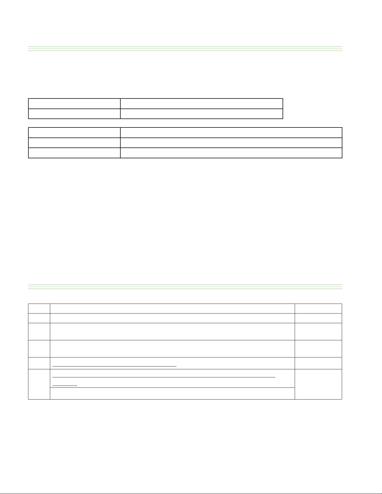
INSTALLATION/OPERATION MANUAL-1&2 PLATEN GARLAND CLAMSHELL GRILLS WITH PRODUCT RECOGNITION
DECLARATION OF CONFORMITY (CE Marked Models)
ALL MODELS:
HE ABOVE PRODUCT SERIES HAS BEEN DESIGNED AND MANUFACTURE IN ACCORDANCE WITH THE FOLLOWING DIRECTIVES AS APPLICABLE AND
T
AMENDED, BASED ON THE LATEST AMENDED HARMONIZED STANDARD
2006/95/EEC LOW VOLTAGE DIRECTIVE
EN60335-1 SAFETY OF HOUSEHOLD AND SIMILAR ELECTRICAL APPLIANCES
2004/108/EC ELECTROMAGNETIC COMPATIBILITY DIRECTIVE
IEC/EN 61000-6-1:2007 EMC - IMMUNITY FOR RESIDENTIAL, COMMERCIAL AND LIGHT-INDUSTRIAL ENVIRONMENTS
IEC/EN 61000-6-3:2007 EMC - EMISSION STANDARD FOR RESIDENTIAL, COMMERCIAL AND LIGHT-INDUSTRIAL ENVIRONMENTS
THIS PRODUCT DOES NOT CONTAIN ASBESTOS. THE MATERIALS USED IN THE PRODUCTS NAMED ABOVE ARE SUITABLE FO CONTACT WITH FOOD IN
ACCORDANCE WITH FRAMEWORK DIRECTIVE FOR FOOD CONTACT MATERIALS AND ARTICLES (89/109/EEC)
AS MODELS:
G
HE FOLLOWING REQUIREMENTS AND TEST SPECIFICATIONS ARE CONSIDERED TO E A SUITABLE BASIS FOR DEMOSTRATING COMPLIANCE OF THE ABOVE
T
PRODUCT(S) WITH THE ESSENTIAL REQUIREMENTS OF THE EUROPEAN GAS APPLIANCE DIRECTIVE (90/396/EEC)
EN 203-1:2005 + A1:2008; EN 203-2-9: 205; EN 437:2003 + A1:2009
N ACCORDANCE WITH ESSENTIAL REQUIREMENT 2.2 IF ANNEX I OF THE EUROPEAN GAS APPLIANCE DIRECTIVE (90/396/EEC), WE GUARANTEE
I
THAT THE MATERIALS USED IN THE ABOVE PRODUCTS ARE APPROPIATE FOR THEIR INTENDED PURPOSE AND WILL WITHSTAND THE TECHNICAL,
CHEMICAL AND THERMAL TO WHICH THEY WILL FORESEE ABLY BE SUBJECTED.
INSTALLATION OPERATION MANUAL HISTORY
Rev# Description Date
0 1&2Platen-1, I/O Manual released April 5, 2012
Page 27, model title changed - Page 29, Slim photo added - Page 42, display photos added -
1
Page 57, new Japan menu.
Recommended plug notes removed, page 21. More information on casters and caster brace,
2
page 20. Push & Pull procedure added, page 39.
3
To change the Programming Standby Alarm, instruction added. Page 53.
LonWork Information & Commissioning To Activate the grill onto the Lonworks
network remove from IOM - information remain in Service Manual. Page 24
4
LonWorks Information, page 43 - removed.
April 17, 2012
August 10, 2012
March 14, 2014
Jan 30, 2015
Page 58
Part #4530667 Rev 4 (30 Jan 15)
Page 59

GARLAND CLAMSHELL GRILLS WITH PRODUCT RECOGNITION INSTALLATION/OPERATION MANUAL-1&2 PLATEN
INDEX
A
Auto mode
Breakfast In Auto mode 42
B
Beef Integrity 45
C
Calibra on Probe 27
Casters Installa on 20
Connec on, Power Supply 21
Content 3, 4
Control Grill Descrip on 39
E
Error Messaging 40
F
Factory Default Se ng 55
Flue Box Back 23
Form, Start-Up 26
M
Mennekes diagram 21
O
Opera on Procedures 40
Q
Quick Connect Coupler 23
R
Recogni on Product 44
S
Safety Notes 6
Supply Required 12, 13, 14, 15
T
Temperature Calibra on 27
Thermocouple Loca ons 30
G
Gas Connec on 23
Gas Specifi ca on 17
Grease Bucket Installa on 23
Part #4530667 Rev 4 (30 Jan 15)
Page 59
Page 60

INSTALLATION/OPERATION MANUAL-1&2 PLATEN GARLAND CLAMSHELL GRILLS WITH PRODUCT RECOGNITION
Installation & Operation Manual
1&2 Platen-1 Models Electric/Gas Clamshell Grills With Product Recognition
Manufactured Exclusively For McDonald’s By
Garland Commercial Ranges
http://www.garland-group.com
 Loading...