

Page 1
INSTALLATION/OPERATION
& SERVICE MANUAL
GARLAND 1 & 2 PLATEN
ELECTRIC & GAS
CLAMSHELL GRILLS
WITH PRODUCT RECOGNITION
MODELS:
MWE2W
MWE2S
MWG2W
MWE1W
MWE1S
MWG1W
FOR YOUR SAFETY:
DO NOT STORE OR USE GASOLINE OR
OTHER FLAMMABLE VAPORS OR LIQUIDS
IN THE VICINITY OF THIS OR ANY OTHER
APPLIANCE
WARNING:
IMPROPER INSTALLATION, ADJUSTMENT,
ALTERATION, SERVICE OR MAINTENANCE
CAN CAUSE PROPERTY DAMAGE, INJURY,
OR DEATH. READ THE INSTALLATION,
OPERATING AND MAINTENANCE
INSTRUCTIONS THOROUGHLY
BEFORE INSTALLING OR
SERVICING THIS EQUIPMENT
PLEASE READ ALL SECTIONS OF THIS MANUAL AND
RETAIN FOR FUTURE REFERENCE.
THIS PRODUCT HAS BEEN CERTIFIED AS
COMMERCIAL COOKING EQUIPMENT AND MUST
BE INSTALLED BY PROFESSIONAL PERSONNEL AS
SPECIFIED.
INSTALLATION AND ELECTRICAL CONNECTION MUST
COMPLY WITH CURRENT CODES:
IN CANADA - THE CANADIAN ELECTRICAL CODE
PART 1 AND / OR LOCAL CODES.
IN USA – THE NATIONAL ELECTRICAL CODE ANSI /
NFPA – CURRENT EDITION.
ENSURE ELECTRICAL SUPPLY CONFORMS WITH
ELECTRICAL CHARACTERISTICS SHOWN ON THE
RATING PLATE.
For Your Safety:
Post in a prominent location, instructions to be
followed in the event the user smells gas. This
information shall be obtained by consulting your
local gas supplier
THIS EQUIPMENT MUST BE INSTALLED AND COMMISSIONED BY A PROFESSIONAL, FACTORY-TRAINED TECHNICIAN.
THIS EQUIPMENT MUST BE OPERATED UNDER AN APPROVED HOOD SYSTEM ONLY.
MANUFACTURED EXCLUSIVELY FOR McDonald's BY
GARLAND COMMERCIAL RANGES
http://www.garland-group.com/
PART #4527466 (12 Aug 2011)
Page 2

Page 3

GARLAND CLAMSHELL GRILLS WITH PRODUCT RECOGNITION INSTALLATION/OPERATION & SERVICE MANUAL - 1&2 PLATEN
.
,
.
,
.
,
.
.
.
.
CONTENTS
INTRODUCTION . . . . . . . . . . . . . . . . . . . . . . . . . . . . . . . . . . 4
WARRANTY. . . . . . . . . . . . . . . . . . . . . . . . . . . . . . . . . . . . . . 4
SHIPPING DAMAGE CLAIM PROCEDURE. . . . . . . . . . . . 5
SAFETY. . . . . . . . . . . . . . . . . . . . . . . . . . . . . . . . . . . . . . . . . . 6
DIMENSIONS SPECIFICATION
Dimensions: Model MWE2W, MWG2W. . . . . . . . . . . . . . . . 8
Dimensions: Model MWE1W, MWG1W. . . . . . . . . . . . . . . . 9
Dimensions: Model MWE2S . . . . . . . . . . . . . . . . . . . . . . . . .10
Dimensions: Model MWE1S . . . . . . . . . . . . . . . . . . . . . . . . .11
INPUT SPECIFICATIONS
• Input Speci cations, ELECTRIC FULL SIZE Grills,
• Input Speci cations,
MWE2W, United States:. . . . . . . . . . . . . . . . . . . . . . . . . . . . .12
WE2W, United States: . . . . . . . . . . . . . . . . . . . . . . . . . . .
• Input Speci cations, ELECTRIC SLIM Grills, MWE2S,
United States: . . . . . . . . . . . . . . . . . . . . . . . . . . . . . . . . . . . . . .12
• Input Speci cations, ELECTRIC FULL SIZE Grills,
•
nput Speci cations,
MWE2W, Canada: . . . . . . . . . . . . . . . . . . . . . . . . . . . . . . . . . .12
WE2W, Canada: . . . . . . . . . . . . . . . . . . . . . . . . . . . . . . . . .
• Input Speci cations, ELECTRIC SLIM Grills, MWE2S,
Canada:. . . . . . . . . . . . . . . . . . . . . . . . . . . . . . . . . . . . . . . . . . . .12
• Input Speci cations, ELECTRIC FULL SIZE Grills,
•
nput Speci cations,
MWE2W, CE Approved & Export: . . . . . . . . . . . . . . . . . . . .12
WE2W, CE Approved & Export:
• Input Speci cations, ELECTRIC SLIM
Grills,MWE2S, CE Approved & Export
• Input Speci cations, ELECTRIC SINGLE PLATEN Grills,
•
nput Speci cations,
MWE1W, North America: . . . . . . . . . . . . . . . . . . . . . . . . . . .13
WE1W, North America: . . . . . . . . . . . . . . . . . . . . . . . . . .
• Input Speci cations, ELECTRIC SINGLE PLATEN Grills,
MWE1W, CE Approved & Export: . . . . . . . . . . . . . . . . . . . .13
• Input Speci cations, ELECTRIC SINGLE PLATEN SLIM
•
nput Speci cations,
Grills, MWE1S, CE Approved & Export:. . . . . . . . . . . . . . .13
rills, MWE1S, CE Approved & Export: . . . . . . . . . . . . .
• Input Speci cations, GAS Grills, 2 Platen MWG2S,
North America:. . . . . . . . . . . . . . . . . . . . . . . . . . . . . . . . . . . . .14
• Input Specifications, GAS Grills, 2 Platen
Input Specifications, GAS Grills, 2 Platen
MWG2W,CE Approved Models:. . . . . . . . . . . . . . . . . . . .14
WG2W,CE Approved Models:
• Input Speci cations, GAS SINGLE PLATEN MWG1W
Grills, North America:. . . . . . . . . . . . . . . . . . . . . . . . . . . . . . .15
• Input Speci cations, GAS SINGLE PLATEN MWG1W
Input Speci cations, GAS SINGLE PLATEN MWG1W
Grills, CE Approved Models: . . . . . . . . . . . . . . . . . . . . . . . .15
rills, CE Approved Models: . . . . . . . . . . . . . . . . . . . . . . .
INSTALLATION & STARTUP
General . . . . . . . . . . . . . . . . . . . . . . . . . . . . . . . . . . . . . . . . . . . .16
Installation Store Responsibilities . . . . . . . . . . . . . . . . . . .16
Items included with the purchase of you new
Grill from manufacturer: . . . . . . . . . . . . . . . . . . . . . . . . . . . .16
Power Supply Connection: . . . . . . . . . . . . . . . . . . . . . . . . . .18
Hood Type & Platen Height. . . . . . . . . . . . . . . . . . . . . . . . . .19
LonWorks Information & Commissioning
To Activate the grill onto the Lonworks network:. . . . .19
LECTRIC FULL SIZE Grills
LECTRIC FULL SIZE Grills
LECTRIC FULL SIZE Grills
. . . . . . . . . . . . . . . . . .
:. . . . . . . . . . . .12
LECTRIC SINGLE PLATEN Grills,
LECTRIC SINGLE PLATEN SLIM
. . . . . . . . . . . . . . . . . .
Start Up Procedure . . . . . . . . . . . . . . . . . . . . . . . . . . . . . . . . .20
Grill Startup Form Sample. . . . . . . . . . . . . . . . . . . . . . . . . . .21
Setting Proper Combustion Level . . . . . . . . . . . . . . . . . . .22
INSTALLATION OF RELEASE MATERIAL . . . . . . . . . . . . 24
INSTALLATION OF SPLASH SHIELD . . . . . . . . . . . . . . . 25
CLEANING & MAINTENANCE . . . . . . . . . . . . . . . . . . . . . 24
GRILL ACCESSORIES . . . . . . . . . . . . . . . . . . . . . . . . . . . . . 28
Te on Wraparound kits . . . . . . . . . . . . . . . . . . . . . . . . . . . . .30
Splash Shield . . . . . . . . . . . . . . . . . . . . . . . . . . . . . . . . . . . . . . .31
Interlock Cord - 5Wire. . . . . . . . . . . . . . . . . . . . . . . . . . . . . . .31
3Phase 4-Wire 50AMP Cord . . . . . . . . . . . . . . . . . . . . . . . . .31
3Phase 4-Wire 30AMP Cord . . . . . . . . . . . . . . . . . . . . . . . . .31
Te on Sheet, Rods & Clips. . . . . . . . . . . . . . . . . . . . . . . . . . .31
DESCRIPTION OF GRILL CONTROL . . . . . . . . . . . . . . . . 32
POSSIBLE ERROR MESSAGES. . . . . . . . . . . . . . . . . . . . . 32
OPERATING PROCEDURES . . . . . . . . . . . . . . . . . . . . . . . 33
General Overview: . . . . . . . . . . . . . . . . . . . . . . . . . . . . . . . . . .33
To turn the grill on: . . . . . . . . . . . . . . . . . . . . . . . . . . . . . . . . .33
Menu Item Library . . . . . . . . . . . . . . . . . . . . . . . . . . . . . . . . . .33
Indicator Lights. . . . . . . . . . . . . . . . . . . . . . . . . . . . . . . . . . . . .34
Standby Mode. . . . . . . . . . . . . . . . . . . . . . . . . . . . . . . . . . . . . .34
To display the current temperatures: . . . . . . . . . . . . . . . .34
Breakfast In Manual mode . . . . . . . . . . . . . . . . . . . . . . . . . .34
Lunch In Manual mode . . . . . . . . . . . . . . . . . . . . . . . . . . . . .34
To Change The Cook Time for a Menu Item . . . . . . . . . .34
Breakfast In Auto mode . . . . . . . . . . . . . . . . . . . . . . . . . . . . .34
Lunch In Auto mode . . . . . . . . . . . . . . . . . . . . . . . . . . . . . . . .35
Transition Cooking. . . . . . . . . . . . . . . . . . . . . . . . . . . . . . . . . .35
To Shutdown Grill. . . . . . . . . . . . . . . . . . . . . . . . . . . . . . . . . . .35
LONWORKS INFORMATION . . . . . . . . . . . . . . . . . . . . . . 35
PATTY PLACEMENT. . . . . . . . . . . . . . . . . . . . . . . . . . . . . . 35
PRODUCT RECOGNITION. . . . . . . . . . . . . . . . . . . . . . . . . 36
COMMON PRODUCT RECOGNITION ISSUES. . . . . . . . . . 36
BEEF INTEGRITY . . . . . . . . . . . . . . . . . . . . . . . . . . . . . . . . 37
PROGRAM LOGIC TREE; PRODUCT MENUS. . . . . . . . . 38
PROGRAM LOGIC TREE; SYSTEM MENUS . . . . . . . . . . 39
PART #4527466 (12 Aug 2011) Page 3
Page 4

INSTALLATION/OPERATION & SERVICE MANUAL - 1&2 PLATEN GARLAND CLAMSHELL GRILLS WITH PRODUCT RECOGNITION
CONTENTS (continued)
CONTROL PROGRAMMING. . . . . . . . . . . . . . . . . . . . . . . 40
Programming Modes; System Setup . . . . . . . . . . . . . . . .40
Programming Modes; Menu Items . . . . . . . . . . . . . . . . . .41
To Restore Factory Defaults for all
Product Menu Items . . . . . . . . . . . . . . . . . . . . . . . . . . . . . . . .43
PROBE CALIBRATION . . . . . . . . . . . . . . . . . . . . . . . . . . . . 44
THERMOCOUPLE LOCATIONS . . . . . . . . . . . . . . . . . . . . 45
FACTORY DEFAULT SETTINGS
Clam Menu Items. . . . . . . . . . . . . . . . . . . . . . . . . . . . . . . . . . .46
Flat Menu Items . . . . . . . . . . . . . . . . . . . . . . . . . . . . . . . . . . . .47
FUNCTION OPTIONS; SYSTEM MENUS . . . . . . . . . . . . 48
ERROR MESSAGES/TROUBLESHOOTING . . . . . . . . . . 49
PLATEN LEVELING (ZEROING) . . . . . . . . . . . . . . . . . . . . 51
TO SET THE REED SWITCHES . . . . . . . . . . . . . . . . . . . . . 52
TO CHANGE THE MAGNET ASSEMBLY . . . . . . . . . . . . . 53
TO REPLACE THE LINEAR ACTUATOR . . . . . . . . . . . . . . 53
TO REPLACE SHAFT SEAL . . . . . . . . . . . . . . . . . . . . . . . . 55
WIRING SHCHEMATIC: MWE2W-STANDARD . . . . . . . 86
WIRING SHCHEMATIC: MWE2S-CE, WYE CONFIG . . . 87
WIRING SHCHEMATIC: MWE2W-CE, WYE CONFIG. . . 88
WIRING SHCHEMATIC: MWG2W . . . . . . . . . . . . . . . . . . 89
WIRING SHCHEMATIC: MWG2W, EXPORT. . . . . . . . . . 90
DECLARATION OF CONFORMITY
(CE Marked Models) . . . . . . . . . . . . . . . . . . . . . . . . . . . . . 91
TO REPLACE SHAFT SEAL & CAP O-RING. . . . . . . . . . . 56
TO UPDATE CONTROL SOFTWARE (main ctrl) . . . . . . 58
TO UPDATE CONTROL SOFTWARE (motor ctrl) . . . . . 59
ELECTRIC HEATING ELEMENTS . . . . . . . . . . . . . . . . . . . 60
1&2 PLATEN PART LIST
PARTS ID: Grill Exterior . . . . . . . . . . . . . . . . . . . . . . . . . . . . . .62
PARTS ID: GRILL Element Electric Models . . . . . . . . . . . .64
PARTS ID: Grill Burner Gas Models . . . . . . . . . . . . . . . . . . .66
PARTS ID: Upper Platen Assembly all Models . . . . . . . .66
PARTS ID: Upper Platen Assembly all Models . . . . . . . .70
PARTS ID: Platen LIfting Mechanism all Models . . . . . .72
WIRING HARNESSES, ALL MODELS . . . . . . . . . . . . . . . 74
WIRING SHCHEMATIC: MWE1W-STANDARD . . . . . . . 80
WIRING SHCHEMATIC: MWE1W/S-CE, WYE CONFIG. 81
WIRING SHCHEMATIC: MWE1W-CE, WYE CONFIG. . . 82
WIRING SHCHEMATIC: MWE1W-CE, WYE CONFIG HK
ONLY. . . . . . . . . . . . . . . . . . . . . . . . . . . . . . . . . . . . . . . . . . . 83
WIRING SHCHEMATIC: MWG1W . . . . . . . . . . . . . . . . . . 84
WIRING SHCHEMATIC: MWG1W-EXPOTY . . . . . . . . . . 85
PART #4527466 (12 Aug 2011)Page 4
Page 5

GARLAND CLAMSHELL GRILLS WITH PRODUCT RECOGNITION INSTALLATION/OPERATION & SERVICE MANUAL - 1&2 PLATEN
INTRODUCTION
The Garland clamshell grill, manufactured exclusively for McDonald’s, provides a method for e cient two-sided cooking,
while accommodating a variety of products. The unit will also serve as a at grill, and meets all of McDonald’s standards for
safety, e ciency, and cleanliness.
WARRANTY
This warranty covers defects in material and workmanship under normal use providing that:
a) the equipment has not been accidentally or intentionally damaged, altered or misused.
b) the equipment is properly installed, adjusted, operated and maintained in accordance with national and local
codes and in accordance with the installation instructions provided with this product.
c) the warranty serial number a xed to the appliance by us has not been defaced, obliterated or removed.
d) an acceptable report for any claim under this warranty is supplied to us.
The equipment warranty coverage remains in force for two (2) years, (parts and labor), from the date the equipment is put
into operation.
The Garland Group agrees to repair or replace, at it’s option, any part that proves to be defective in material or
workmanship at no charge for the part or normal labor.
We assume no responsibility for installation, adjustments, diagnosis, or normal maintenance such as: lubrication of springs
or valves. We exclude failures caused by erratic voltage or gas supplies.
We assume no responsibility for travel costs beyond 100 miles round trip, travel other than overland, and overtime
costs of repair.
We exclude broken glass, paint and porcelain nish, surface rust, gasket material, ceramic material, light bulbs and
fuses from normal coverage.
We exclude damage or dysfunction caused by re, ood, and like “Acts of God” that are beyond the control of The
Garland Group.
The Garland Group’s liability on a claim of warranty shall not exceed the price of the material and/or service, which caused
the claim.
This warranty is limited and is in lieu of all other warranties, expressed or implied. The Garland Group, our employees,
or our agents shall not be held liable for any claims of personal injury or consequential damage or loss.
This warranty gives you speci c legal rights, and you may have other rights which vary from state to state.
SHIPPING DAMAGE CLAIM PROCEDURE
Please note that the Garland equipment was carefully inspected and packed by skilled personnel before leaving the
factory. The transportation company assumes full responsibility for safe delivery upon acceptance of the equipment. What
to do if the equipment arrives damaged:
1. File a claim immediately regardless of the extent of damage.
2. Be sure to note, “visible loss or damage,” on the freight bill or express receipt and have the person making the delivery
sign it.
3. Concealed loss or damage: if damage is unnoticed until the equipment is unpacked, notify the freight company
immediately, (within 15 days), and le a concealed damage claim.
PART #4527466 (12 Aug 2011) Page 5
Page 6

INSTALLATION/OPERATION & SERVICE MANUAL - 1&2 PLATEN GARLAND CLAMSHELL GRILLS WITH PRODUCT RECOGNITION
SAFETY
• DISCONNECT ALL POWER SUPPLIES BEFORE OPENING PANELS FOR SERVICING.
• KEEP THE APPLIANCE AREA FREE AND CLEAR FROM COMBUSTIBLES.
• DO NOT OBSTRUCT THE FLOW OF COMBUSTION AND VENTILATION AIR.
• ALLOW A MINIMUM OF 24 INCHES UNOBSTRUCTED CLEARANCE IN FRONT OF THE UNIT FOR
SERVICING
THIS APPLIANCE IS FOR PROFESSIONAL USE AND SHALL BE USED ONLY BY QUALIFIED PERSONNEL.
WARNING: Accessible parts may become hot during use. Young children should be kept away. This appliance is not intended for
use by persons (including children) with reduced physical, sensory or mental capabilities, or lack of experience and knowledge,
unless they have been given supervision or instruction concerning use of the appliance by a person responsible for their safety.”
CAUTION: THIS EQUIPMENT MUST ONLY BE OPERATED UNDER AN APPROVED HOOD SYSTEM IN ACCORDANCE WITH
LOCAL REGULATIONS IN FORCE.
DO NOT OPERATE THE GRILL UNLESS IT HAS BEEN COMMISSIONED (START-UP) BY A FACTORY AUTHORIZED SERVICE CENTER.
DO NOT operate the grill without reading this operation manual.
DO NOT operate the clamshell grill unless it has been properly installed and grounded.
DO NOT operate the clamshell grill unless all service and access panels are in place and fastened properly.
Means of disconnection, must be incorporated in the xed wiring in accordance with local wiring rules (such as a switch, fuse,
or circuit breaker). External equipotential bonding conductor provided on rear of appliance. Use as applicable, in accordance
with local wiring rules.
The Garland clamshell grill is a semi-automatic cooking appliance. The upper platen is lowered automatically, following the
manual, single-handed initiation of the cooking cycle, and raised automatically upon completion of the cooking cycle.
When two sided cooking, the area between the upper platen and the griddle plate should be regarded as a “danger zone”.During two sided cooking the operator must not be within this danger zone. When used as a at grill, then this area is no longer
a danger zone, the platens do not move. For whatever reason, be it cleaning, maintenance, normal operation, any exposed
person must use extreme caution if within this danger zone. Temperatures on solid cooking surfaces are intended to operate
above 120C (250F).
In two sided cooking the upper platen remains in the lowered position by nature of it’s own weight. It is not locked down. It can
be raised by lifting of the handle on the front of the platen, which pivots the platen about its rear mounting point.
The clamshell grill must only be used for single and two sided cooking of foodstu s in a McDonald’s store.
SOUND EMISSIONS: Sound pressure levels at the grill operator’s position may exceed 70 dB(A) when audible alarms are active.
Audible volume may be adjusted to below 70 dB(A). See Control Programming Section.
WARNING: To avoid serious personal injury: DO NOT attempt to repair or replace any part of the clamshell grill unless all main
power supplies to the grill have been disconnected.
USE EXTREME CAUTION in setting up, operating and cleaning the clamshell grill to avoid coming in contact with hot grill
surfaces or hot grease. Suitable protective clothing should be worn to prevent the risk of burns.
PART #4527466 (12 Aug 2011)Page 6
Page 7

GARLAND CLAMSHELL GRILLS WITH PRODUCT RECOGNITION INSTALLATION/OPERATION & SERVICE MANUAL - 1&2 PLATEN
SAFETY (continued)
WARNING: This appliance must not be cleaned with a water jet. DO NOT apply ice to a HOT grill surface.
NOTE: All warning labels and markings on the grill, which call attention to further dangers and necessary precautions.
HAZARD COMMUNICATION STANDARD, (HCS) - The procedures in this manual include the use of chemical products. These
chemical products will be printed in bold face, followed by the abbreviation (HCS) in the text portion of the procedure. See the
Hazard Communication Standard, (HCS) manual for the appropriate Material Safety Data Sheet(s), (MSDS).
WARNING: After turning the master power switch to the START position, the grill will go through an initialization process. If the
upper platens are in the lowered position they will return to their raised upper position.
MAINTENANCE - the platen support arms carriage block bearing bushes, the platen adjuster nuts, the platen support (shoulder)
bolt and the cam follower should be checked annually for wear. Should there be any noticeable play in the bearing bushes and
any visible wear on the platen adjuster nuts, platen support bolts or cam follower, then they must be replaced.
MAINTENANCE - the audible alarm that sounds at the end of a cook cycle is to advise the operator that the platen is about to
move. The function of this device may be tested by pushing the left hand CANCEL button. If no sound is heard, ensure that the
alarm volume is not set to low in SYSTEM SETUP. If there is still no sound then a service engineer should be called out to rectify
the fault.
SERVICE AND CLEANING - The grill may be secured in the grill bay by the installer using two anchors that lock onto the front
casters. If the grill is to be moved out of the bay for cleaning or service, remove the anchor from each caster by turning the knob
counterclockwise to loosen the retainer. When the retainer is free of the caster, lay the assembly aside on the oor.
CLEANING - NEVER clean the grill, interior or exterior, using a high-pressure sprayer, water jet, or any other liquid sprayer.
NOTE: If anchors are present, the anchor assembly remains fastened to the back wall of the grill bay. After service or cleaning
is complete, return the grill to its position in the bay and reattach the anchors by placing the retainer on the caster post and
turning the knob clockwise to tighten. For safety reasons, the grill must be secured in the grill bay in this manner before operation can resume.
PART #4527466 (12 Aug 2011) Page 7
Page 8

INSTALLATION/OPERATION & SERVICE MANUAL - 1&2 PLATEN GARLAND CLAMSHELL GRILLS WITH PRODUCT RECOGNITION
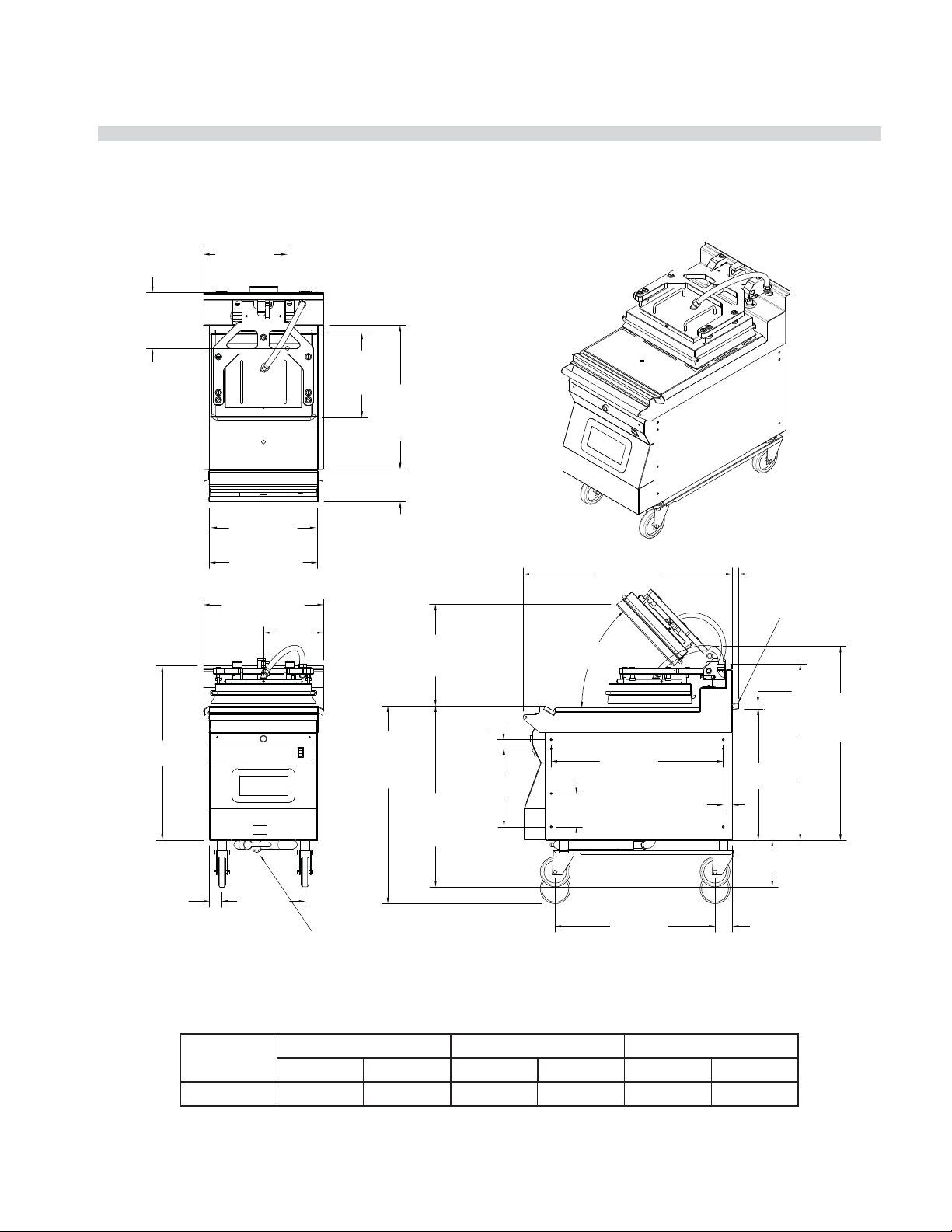
DIMENSION SPECIFICATION
Dimensions:
Models MWE2W, MWG2W
*CABLE ENTRANCE(S) VARY SLIGHTLY DEPENDING ON UNIT CONFIGURATION
25.95in
23.69in
602mm
BOTTOM GAS ONLY
INLET 3/4" NPT
9.25in
235mm
*BOTTOM CABLE
ENTRANCE
14.11in
358mm
*BOTTOM
CABLE
ENTRANCE
659mm
BOTTOM GAS ONLY
INLET 3/4" NPT
4.64in
118mm
TYP. GAS
ONLY
7.18in
182mm
TYP. GAS
ONLY
14.06in
357mm
PLATEN DEPTH
PLATE DEPTH
24.00in
610mm
29.15in
740mm
6.40in
163mm
GAS ONLY
17.53in
445mm
PLATEN WIDTH
FRONT GAS CONNECTION KIT
GAS ONLY
36.00in
914mm
PLATE WIDTH
38.00in
965mm
18.00in
457mm
23.82in
605mm
36.03in
915mm
10.00in
254mm
32.25in
819mm
MAX. COOK
HEIGHT
6.10in
155mm
17.000in
432mm
MAX. OP.
30.00in
762mm
MIN. COOK
HEIGHT
57mm
5.48in
139mm
1.50in
38mm
2.25in
13.06in
332mm
46.8°
MAX. OP.
5.56in
141mm
34.96in
888mm
28.76in
731mm
26.68in
678mm
1.53in
39mm
GAS ONLY
22.10in
561mm
GAS ONLY
7.75in
197mm
2.92in
74mm
.97in
25mm
.93in
24mm
GAS ONLY
29.41in
747mm
PLATEN
DOWN
32.38in
823mm
PLATEN
UP
MODEL
HEIGHT* WIDTH DEPTH
inches mm inches mm inches mm
MWE2W 29.2 740 36.0 915 34.9 887
*Height not including casters
PART #4527466 (12 Aug 2011)Page 8
Page 9
GARLAND CLAMSHELL GRILLS WITH PRODUCT RECOGNITION INSTALLATION/OPERATION & SERVICE MANUAL - 1&2 PLATEN
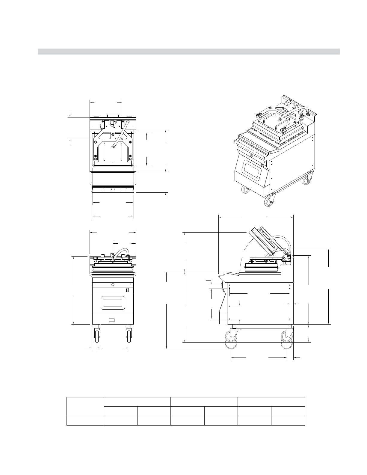
DIMENSION SPECIFICATION
Dimensions:
Models: MWE1W, MWG1W
14.11"
(358mm)
BOTTOM CABLE
ENTRANCE
9.25"
(235mm)
BOTTOM CABLE
ENTRANCE
14.06"
(357mm)
PLATTEN
DEPTH
24.00"
(610mm)
PLATE
DEPTH
5.48"
(139mm)
17.53"
(445mm)
PLATTEN WIIDTH
29.15"
(741mm)
18.00"
(457mm)
PLATE WIIDTH
20.00"
(508mm)
(254mm)
10.00"
33.00"
(838mm)
MAX COOK
HEIGHT
17.00"
(432mm)
MAX OPEN
30.75"
(781mm)
MIN COOK
HEIGHT
1.50"
(38mm)
13.06"
(332mm)
(888mm)
46.8° MAX OPEN
(731mm)
5.56"
(141mm)
34.96"
28.76"
1.53"
(39mm)
.97
(559mm)
(25mm)
.93"
(24mm)
22"
8.50"
(216mm)
GAS ONLY
29.41"
(747mm)
PLATTEN
DOWN
32.38"
(823mm)
PLATTEN
UP
2.06"
(52mm)
(353mm)
MODEL
13.88"
FRONT GAS CONNECTION KIT
GAS ONLY
26.68"
(678mm)
2.92"
(74mm)
HEIGHT* WIDTH DEPTH
inches mm inches mm inches mm
MWE1W 29.2 740 18.0 457 34.9 887
*Height not including casters
PART #4527466 (12 Aug 2011) Page 9
Page 10
INSTALLATION/OPERATION & SERVICE MANUAL - 1&2 PLATEN GARLAND CLAMSHELL GRILLS WITH PRODUCT RECOGNITION
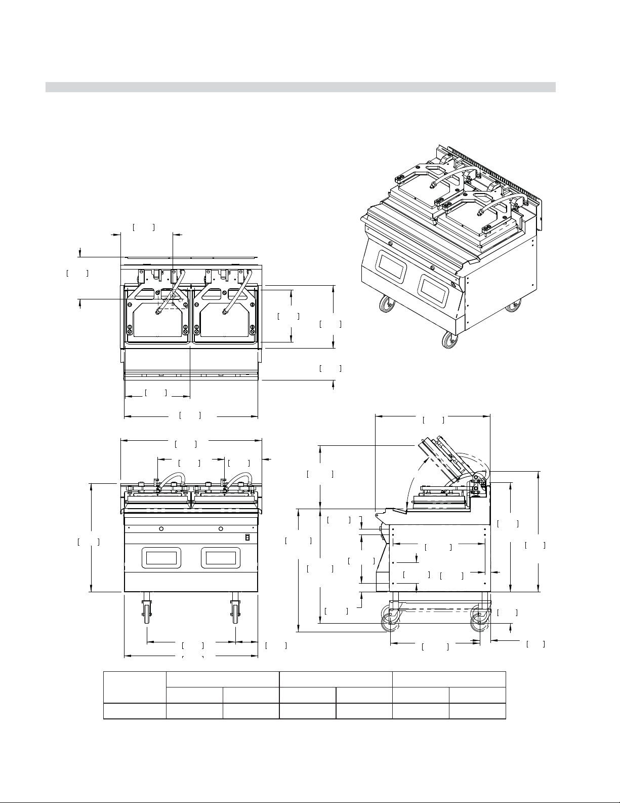
DIMENSION SPECIFICATION
Dimensions:
Model MWE2S
*CABLE ENTRANCE(S) VARY SLIGHTLY DEPENDING ON UNIT CONFIGURATION
14.11in
358mm
*BOTTOM
CABLE
ENTRANCE
11.28in
287mm
*BOTTO M CABLE
ENTRANCE
14.06in
357mm
PLATEN DEPTH
17.00in
432mm
PLATE DEPTH
29.15in
740mm
17.53in
445mm
PLATEN
WIDTH
36.00in
914mm
PLATE WIDTH
38.00in
965mm
18.00in
457mm
23.82in
605mm
36.03in
10.00in
254mm
MAX. COOK
6.10in
155mm
33.00in
838mm
HEIGHT
8.51in
216mm
17.000in
432mm
MAX. OP.
1.50in
38mm
30.75in
781mm
MIN. COOK
HEIGHT
2.25in
57mm
13.06in
332mm
46.8°
MAX. OP.
5.56in
141mm
31.02in
787mm
24.71in
628mm
24.00in
610mm
1.53in
39mm
29.41in
747mm
PLATEN
DOWN
8.50in
216mm
32.38in
823mm
PLATEN
UP
2.92in
74mm
MODEL
HEIGHT* WIDTH DEPTH
inches mm inches mm inches mm
MWE2S 29.2 740 36.0 915 31.0 787
*Height not including casters
PART #4527466 (12 Aug 2011)Page 10
Page 11
GARLAND CLAMSHELL GRILLS WITH PRODUCT RECOGNITION INSTALLATION/OPERATION & SERVICE MANUAL - 1&2 PLATEN
DIMENSION SPECIFICATION
Dimensions:
Model MWE1S
14.11"
(358mm)
BOTTOM CABLE
ENTRANCE
9.25"
(235mm)
BOTTOM CABLE
ENTRANCE
14.06"
17.53"
(445mm)
PLATTEN WIIDTH
18.00
(457mm)
PLATE WIIDTH
20.00"
(508mm)
10.00
(254mm)
(357mm)
PLATTEN
DEPTH
17.00"
(432mm)
PLATE
DEPTH
8.50"
(216mm)
17.00
(432mm)
MAX OPEN
31.00"
(787mm)
46.8° MAX OPEN
1.50"
30.75"
(781mm)
MIN COOK
HEIGHT
(38mm)
13.06"
(332mm)
5.56"
(141mm)
24.72"
(628mm)
24.00"
(610mm)
29.15"
(741mm)
2.06"
(52mm)
MODEL
33.00"
(838mm)
MAX COOK
HEIGHT
13.88"
(353mm)
HEIGHT* WIDTH DEPTH
inches mm inches mm inches mm
MWE2S 29.2 740 18.0 457 31.0 787
*Height not including casters
1.53"
(39mm)
29.41"
(747mm)
PLATTEN
DOWN
8.50"
(216mm)
2.92"
(74mm)
32.38"
(823mm)
PLATTEN
UP
PART #4527466 (12 Aug 2011) Page 11
Page 12

INSTALLATION/OPERATION & SERVICE MANUAL - 1&2 PLATEN GARLAND CLAMSHELL GRILLS WITH PRODUCT RECOGNITION
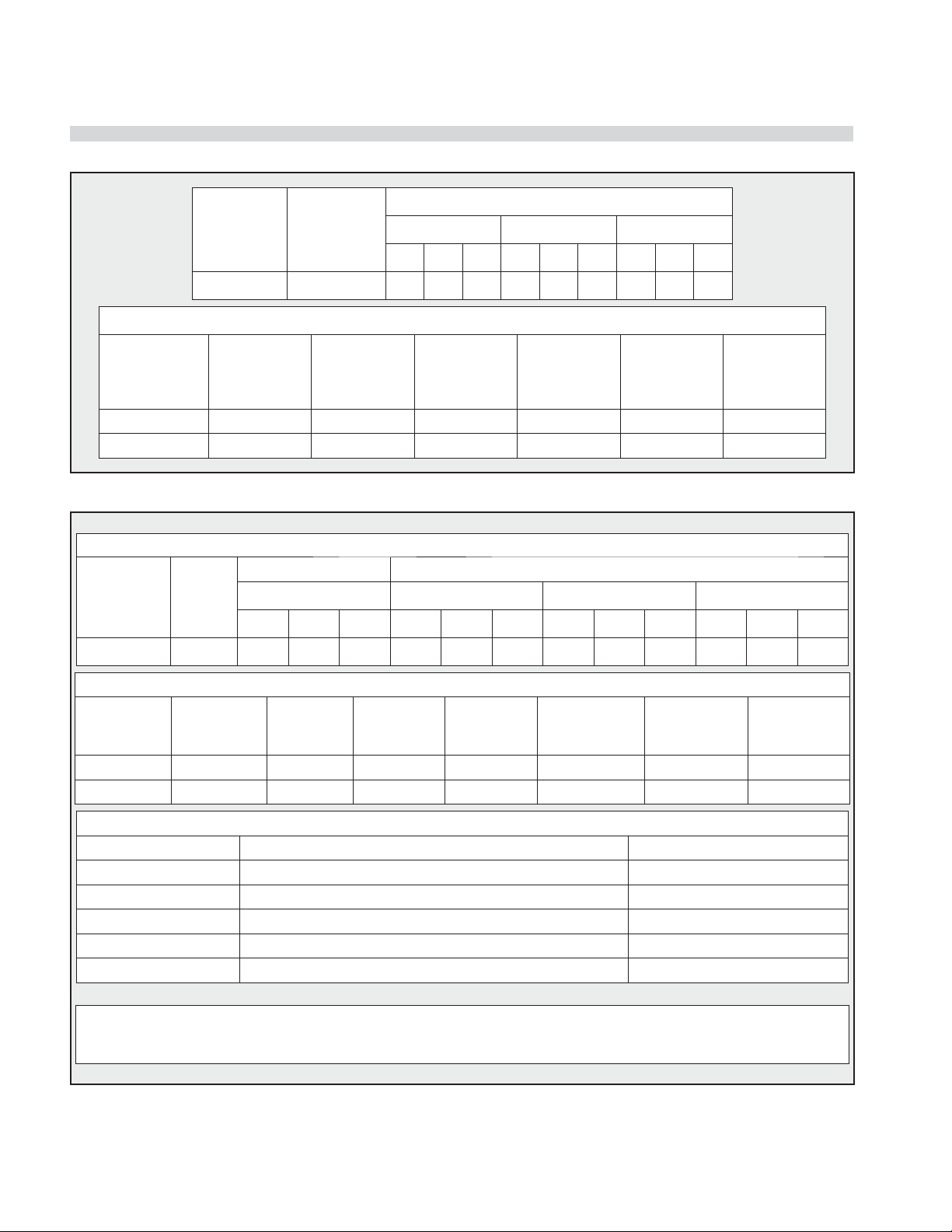
INPUT SPECIFICATIONS
Input Speci cations, ELECTRIC FULL SIZE Grills, MWE2W, United States:
SUPPLY
REQUIRED
INPUT 1 10.6 29.5 29.5 29.5 27.9 27.9 27.9 25.5 25.5 25.5
INPUT 2 10.6 29.5 29.5 29.5 27.9 27.9 27.9 25.5 25.5 25.5
TOTAL
KW
LOAD
208V 220V 240V
L1 L2 L3 L1 L2 L3 L1 L2 L3
NOMINAL AMPS PER LINE
Input Speci cations, ELECTRIC SLIM Grills, MWE2S, United States:
SUPPLY
REQUIRED
INPUT 1 8.1 24.2 24.2 24.2 22.9 22.9 22.9 21 21 21
INPUT 2 8.1 24.2 24.2 24.2 22.9 22.9 22.9 21 21 21
TOTAL
KW
LOAD
208V 220V 240V
L1 L2 L3 L1 L2 L3 L1 L2 L3
NOMINAL AMPS PER LINE
Input Speci cations, ELECTRIC FULL SIZE Grills, MWE2W, Canada:
SUPPLY
REQUIRED
INPUT 21.2 59 59 59 51 51 51
TOTAL
KW
LOAD
208V 240V
L1 L2 L3 L1 L2 L3
NOMINAL AMPS PER LINE
Input Speci cations, ELECTRIC SLIM Grills, MWE2S, Canada:
SUPPLY
REQUIRED
INPUT 16.2 48.4 38.2 48.4 42 33.2 42
TOTAL
KW
LOAD
L1 L2 L3 L1 L2 L3
NOMINAL AMPS PER LINE
208V 240V
Input Speci cations, ELECTRIC FULL SIZE Grills, MWE2W, CE Approved & Export:
MWE2W,CE WYE CONFIG
SUPPLY
REQUIRED
INPUT 22.0 2.10 33.5 33.4 33.4 2.00 31.9 31.8 31.8 1.98 30.7 30.6 30.6 748
TOTAL
KW
LOAD
380V (220V-N) 400V (230V-N) 415V (240V-N)
L1/N L1 L2 L3 L1/N L1 L2 L3 L1/N L1 L2 L3
NOMINAL AMPS PER LINE
Input Speci cations, ELECTRIC SLIM Grills, MWE2S, CE Approved & Export:
MWE2S,CE WYE CONFIG
NOMINAL AMPS PER LINE
SUPPLY
REQUIRED
INPUT 16.5 0.3 33.6 20.8 20.8 0.25 31.9 19.8 19.8 0.24 30.7 19.1 19.1 748
TOTAL
KW
LOAD
380V (220V-N) 400V (230V-N) 415V (240V-N)
L1/N L1 L2 L3 L1/N L1 L2 L3 L1/N L1 L2 L3
MENNEKES
PLUG &
RECEPTACLE
MAY BE
REQUIRED
MENNEKES
PLUG &
RECEPTACLE
MAY BE
REQUIRED
PART #4527466 (12 Aug 2011)Page 12
Page 13

GARLAND CLAMSHELL GRILLS WITH PRODUCT RECOGNITION INSTALLATION/OPERATION & SERVICE MANUAL - 1&2 PLATEN
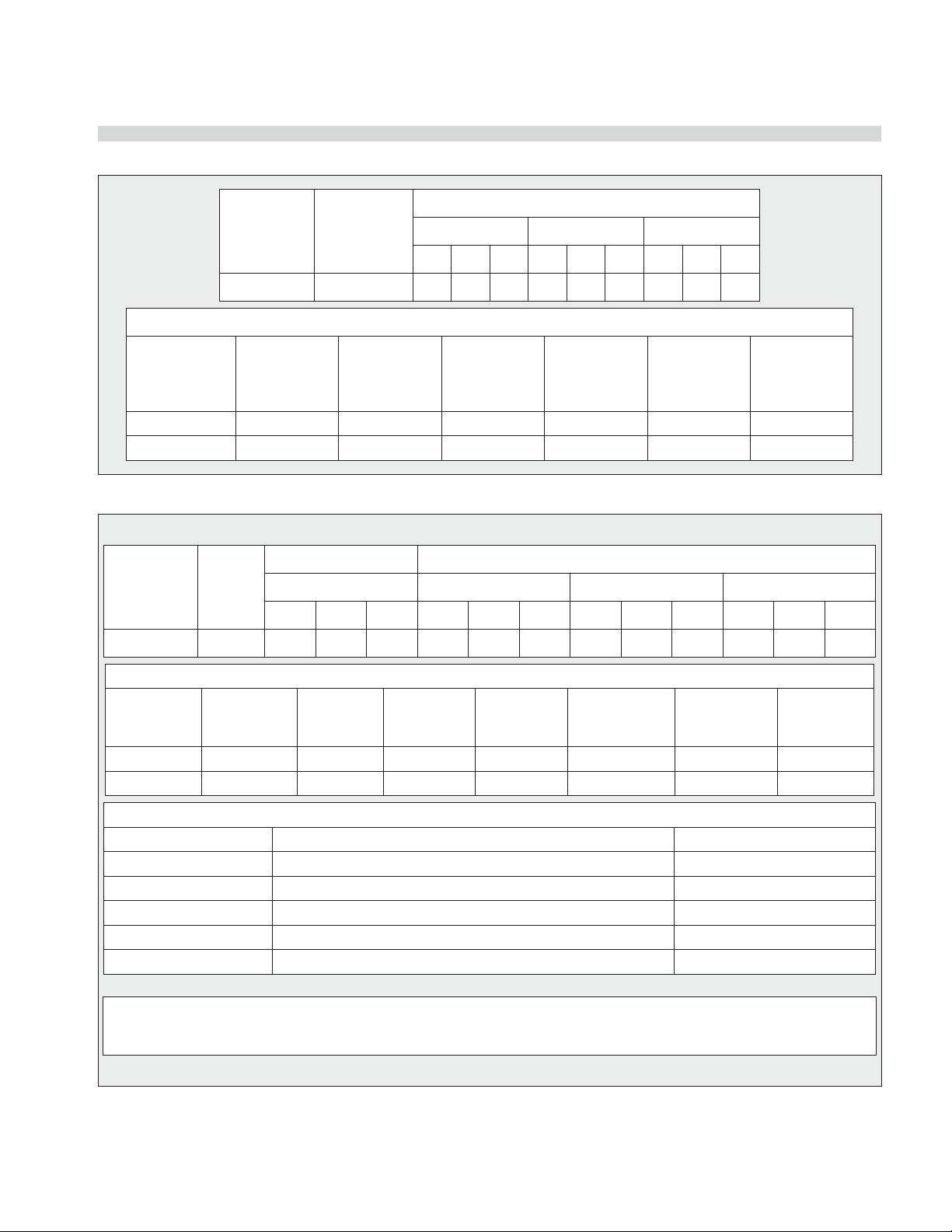
INPUT SPECIFICATIONS (continued)
Input Speci cations, ELECTRIC SINGLE PLATEN Grills, MWE1W, North America:
SUPPLY
REQUIRED
INPUT 1 10.6 29.5 29.5 29.5 27.9 27.9 27.9 25.5 25.5 25.5
TOTAL
KW
LOAD
208V 220V 240V
L1 L2 L3 L1 L2 L3 L1 L2 L3
NOMINAL AMPS PER LINE
Input Speci cations, ELECTRIC SINGLE PLATEN Grills, MWE1W, CE Approved & Export:
TOTAL KW LOAD
SUPPLY
REQUIRED
INPUT 10.6 10.0 10.6 16.1 16.1 16.5 16.3 15.3 15.3 14.8 14.8 15.1 748
380V 400V 415V
380V 400V 415V
L1 L2 L3 L1 L2 L3 L1 L2 L3
NOMINAL AMPS PER LINE
MENNEKES
PLUG &
RECEPTACLE
MAY BE
REQUIRED
Input Speci cations, ELECTRIC SINGLE PLATEN SLIM Grills, MWE1S, CE Approved & Export:
NOMINAL AMPS PER LINE
SUPPLY
REQUIRED
INPUT 8.1 16.1 16.1 5.1 15.3 15.3 4.9 14.7 14.7 4.7 748
TOTAL
KW
LOAD
380V 400V 415V
L1 L2 L3 L1 L2 L3 L1 L2 L3
MENNEKES
PLUG &
RECEPTACLE
MAY BE
REQUIRED
PART #4527466 (12 Aug 2011) Page 13
Page 14
INSTALLATION/OPERATION & SERVICE MANUAL - 1&2 PLATEN GARLAND CLAMSHELL GRILLS WITH PRODUCT RECOGNITION
INPUT SPECIFICATIONS (continued)
Input Speci cations, GAS Grills, 2 Platen MWG2W North America:
TOTAL
SUPPLY
INPUT 1 11.2kW 31.0 31.0 31.0 29.5 29.5 29.5 27.0 27.0 27.0
kW
LOAD
208V / 60Hz 220V / 60Hz 240V / 60Hz
L1 L2 L3 L1 L2 L3 L1 L2 L3
NOMINAL AMPS PER LINE
GAS INPUT
MAX INPUT
GAS
NATURAL GAS 32,000 64,000 #35 50% 7.0 3.5
PROPANE 32,000 64,000 1.75mm 50% 11.0 10.0
NET PER
BURNER
BTU/H
TOTAL INPUT
RATING
BTU/H
INJECTOR
SIZE
AIR SHUTTER
SETTING
*
SUPPLY
PRESSURE
IN W.C.
BURNER
MANIFOLD
PRESSURE
IN W.C.
Input Speci cations, GAS Grills, 2 Platen MWG2W CE Approved Model:
ELECTRICAL REQUIREMENTS: 3N~ 50Hz (3 Phase + N , 4-wire)
TOTAL
kW
LOAD
INPUT 1 9.8 3.3 3.3 3.3 14.9 14.9 14.9 14.2 14.2 14.2 13.6 13.6 13.6
LOADING: (kW/PHASE) NOMINAL AMPS PER LINE
380V / 400V / 415V 380V 400V 415V
L1/N L2/N L3/N L1 L2 L3 L1 L2 L3 L1 L2 L3
GAS INPUT
MAX INPUT
GAS GROUP
G20 NG 8.6 17.2 2.64mm 9.0 20/25 8.7 1.82m3/h
G31 LPG 8.6 17.2 1.61mm 9.0 37/50 24.9 1.34kg/h
CATEGORY DESTINATION COUNTRIES SUPPLY PRESSURE (mbar)
NET PER
BURNER kW
I
2H
I
2E
I
3P
I
3P
I
3P
TOTAL INPUT
RATING kW
AT, CH, CZ, DK, ES, FI, GB, IE, IS, IT, NO, PT, SE 20
INJECTOR
SIZE
BE, CH, CZ, ES, FR, GB, GR, IE, LU 37
BE, CH, DE, CZ, ES, FR, NL 50
AIR SHUTTER
SETTING mm
*
GAS CATEGORIES
DE, LU 20
NL 30
SUPPLY
PRESSURE
mbar
BURNER
PRESSURE
mbar
VOLUMETRIC
GAS RATE
(*) NOTE: Air shutter setting may vary by region. Only a qualify service technician should make adjustments
for proper combustion
PART #4527466 (12 Aug 2011)Page 14
Page 15
GARLAND CLAMSHELL GRILLS WITH PRODUCT RECOGNITION INSTALLATION/OPERATION & SERVICE MANUAL - 1&2 PLATEN
INPUT SPECIFICATIONS (continued)
Input Speci cations, GAS SINGLE PLATEN MWG1W Grills, North America:
TOTAL
SUPPLY
INPUT 1 5.6kW 15.6 15.6 15.5 14.7 14.7 14.7 13.5 13.5 13.5
kW
LOAD
208V / 60Hz 220V / 60Hz 240V / 60Hz
L1 L2 L3 L1 L2 L3 L1 L2 L3
NOMINAL AMPS PER LINE
GAS INPUT
MAX INPUT
GAS
NATURAL GAS 32,000 32,000 #35 50% 7.0 3.5
PROPANE 32,000 32,000 1.75mm 50% 11.0 10.0
NET PER
BURNER
BTU/H
TOTAL INPUT
RATING
BTU/H
INJECTOR
SIZE
AIR SHUTTER
SETTING
*
SUPPLY
PRESSURE
IN W.C.
BURNER
MANIFOLD
PRESSURE
IN W.C.
Input Speci cations, GAS SINGLE PLATEN MWG1W Grills, CE Approved Model:
TOTAL
kW
LOAD
INPUT 1 5.7kW 1.8 1.8 1.9 8.5 8.5 8.9 8.1 8.1 8.5 7.8 7.8 8.2
LOADING: (kW/PHASE) NOMINAL AMPS PER LINE
380V / 400V / 415V 380V 400V 4150V
L1/N L2/N L3/N L1 L2 L3 L1 L2 L3 L1 L2 L3
GAS INPUT
MAX INPUT
GAS GROUP
G20 NG 8.6 8.6 2.64mm 9.0 20/25 8.7 0.91m3/h
G31 LPG 8.6 8.6 1.61mm 9.0 37/50 24.9 0.67kg/h
CATEGORY DESTINATION COUNTRIES SUPPLY PRESSURE (mbar)
NET PER
BURNER kW
I
2H
I
2E
I
3P
I
3P
I
3P
TOTAL INPUT
RATING kW
AT, CH, CZ, DK, ES, FI, GB, IE, IS, IT, NO, PT, SE 20
INJECTOR
SIZE
BE, CH, CZ, ES, FR, GB, GR, IE, LU 37
BE, CH, DE, CZ, ES, FR, NL 50
AIR SHUTTER
SETTING mm
*
GAS CATEGORIES
DE, LU 20
NL 30
SUPPLY
PRESSURE
mbar
BURNER
PRESSURE
mbar
VOLUMETRIC
GAS RATE
(*) NOTE: Air shutter setting may vary by region. Only a qualify service technician should make adjustments
for proper combustion
PART #4527466 (12 Aug 2011) Page 15
Page 16

INSTALLATION/OPERATION & SERVICE MANUAL - 1&2 PLATEN GARLAND CLAMSHELL GRILLS WITH PRODUCT RECOGNITION
INSTALLATION & STARTUP
General:
• In Canada or USA: The installation must comply with
local codes, or in the absence of local codes, with
the National Fuel Gas Code, ANSI Z223.1/NFPA 54, or
the Natural Gas and Propane Installation Code, CSA
B149.1, as applicable
• The appliance and its individual shut-o (supplied by
others) must be disconnected from the gas supply
piping system durin ay pressure testing of that system
at pressures in excess of 1/2 PSIG (3.45 KPA).
• The appliance must be isolated from the gas supply
piping by closing its individual manual shut-o
(supplied by others) during any pressure testing of the
gas supply piping system at test pressures equal to or
less than 1/2PSIG (3.45KPA)
Installation Store Responsibilities:
• The installation shall be made with a connector
that complies with the Standard for Connectors for
Moveable Gas Appliances, ANSI Z21.69/CSA 6.16,
and quick-disconnects device that complies with the
Standard for Quick Disconnects for Use with Gas Fuel,
ANSI Z21.41/CSA 6.9.
• The front Casters on the appliance are equipped with
brakes to limit the movement of the appliance without
placing any strain on the connector or quick disconnect
device or its associated piping.
• Please be aware: required restraint is attached to a
bracket, (which is located on the rear caster closest
to the gas connection) and if disconnection of the
restraint is necessary, be sure to reconnect the device
after the appliance has been returned to its original
position.
• “Adequate clearance must be provide for air opening
into the combustion chamber, and for proper servicing”
• Not intended to be installed adjacent to combustible
walls or on combustible oors.
• Ensure grill has been installed by a competent trained
installation person.
• Ensure store readiness of utilities, product & personnel.
• Contacting your local Garland Factory Authorized
Service Center for a startup date.
• Participate in the startup to ensure a successful startup
and familiarity with the grill.
• Conduct training with your crew personnel to ensure
maximum utilization of the grill.
Once the installation is complete as per the procedures
below, a factory authorized service company MUST startup
the grill according to Garland Commercial Ranges startup
standards.
A startup DOES NOT include:
1. Uncrating the unit
2. Placing the unit in its position under the exhaust hood.
3. Leveling the grill on the oor under the exhaust hood.
4. Attaching the supply cord(s) unless supplied by the
factory.
5. Making adjustments to the ventilation system.
6. Sheet metal work required due to improper exhaust
hood application.
7. Adjusting the grill to achieve beef integrity that
deviates from the McDonalds standard.
A start-up DOES include:
1. Veri cation of supply voltage and, if applicable gas
supply.
2. Leak test and as pressure check on gas grills.
3. Electrical safety check.
4. Verifying operation of grill by allowing unit to attain set
temperature.
5. Verify operation of platens, if applicable, and timer
functions.
6. Ensure time out alarm is functional and platens raise (if
applicable)
7. Set proper gas and verify with beef integrity check that
two consecutive runs yield the approved beef integrity
results as per McDonalds standards.
8. Conduct brief training to store manager on the
operation of the grill.
WARNING: PLEASE READ INSTALLATION INSTRUCTIONS CAREFULLY. FAILURE TO PERFORM
THESE STEPS CAN RESULT IN EQUIPMENT FAILURE, DAMAGE AND / OR VOID OF WARRANTY.
PART #4527466 (12 Aug 2011)Page 16
Page 17

GARLAND CLAMSHELL GRILLS WITH PRODUCT RECOGNITION INSTALLATION/OPERATION & SERVICE MANUAL - 1&2 PLATEN
INSTALLATION & STARTUP (continued)
Items included with the purchase of your
new grill from manufacturer:
1. One (1) grill
2. One (1) gas hose (for gas grills only)
3. One (1) box containing:
a. Six (6) release material sheet
b. Release material clips
b–a. Eight (8) release material clips (2 Platen Grill)
b–b. Four (4) release material clips (1 Platen Grill)
c. Release material rear rods.
c–a. Two (2) release material rear rods (2 Platen Grill)
c–b. One (1) release material rear rods (1 Platen Grill)
4. One (1) box containing four (4) casters.
Items NOT INCLUDED from the manufacturer
and should be purchased from the KES:
1. Any electrical cords needed for application.
2. Any ue box needed for application.
3. Any grease buckets or grease rails needed for
application.
1
2
3
4
Note:
ĺUnpack Unit (Single or Double Platen), Only
Cut Straps That Secure Unit To Pallet.
ĺDO NOT Remove Brace 1 & 2, AND DO NOT
CUT STRAPS 3 & 4.
2. Tip unit over on its back. Install caster channels and
casters as shown. After installing, lock the rear casters.
4
THE FOLLOWING INSTALLATION
PROCEDURE CAN BE PERFORMED BY A:
• FACTORY AUTHORIZED SERVICE CENTER
• AN APPROVED INSTALLATION PERSON APPROVED BY
PURCHASER OF GRILL
• LICENSED INSTALLER CONTRACTED BY KES (KITCHEN
EQUIPMENT SUPPLIER)
1. Uncrate unit from crating material
CAUTION:
PRIOR TO INSTALLATION, CHECK THE ELECTRICAL
SUPPLY TO ENSURE INPUT VOLTAGE AND PHASE
MATCH THE EQUIPMENT VOLTAGE RATING AND
PHASE. MANY LOCAL CODES EXIST, IT IS THE
RESPONSIBILITY OF THE OWNER/INSTALLER TO
COMPLY WITH THESE CODES.
NOTE: ENSURE THAT PLATENS ARE STRAPPED
DOWN SECURELY THROUGH STEP 3 TO PREVENT
PLATENS FROM RAISING. SEVERE DAMAGE MAY
OCCUR.
3. Carefully rotate grill back on its casters. Now you may
cut and remove the platen securing straps.
4. Remove back body side and Install power cords per
your country / area’s speci cations.
WARNING:
The appliances must be electrically grounded in
accordance with local codes, or in the absence of
local codes, with the National Electrical Code ANSI/
NFPA 70, or the Canadian Electrical Code CSA C22.1
as applicable.
PART #4527466 (12 Aug 2011) Page 17
Page 18

INSTALLATION/OPERATION & SERVICE MANUAL - 1&2 PLATEN GARLAND CLAMSHELL GRILLS WITH PRODUCT RECOGNITION
INSTALLATION & STARTUP (continued)
POWER SUPPLY CONNECTION:
All electric connections must be made by a quali ed,
properly equipped technician.
NOTE: WIRING DIAGRAM LOCATED INSIDE
LOWER FRONT PANEL.
“DISCONNECT POWER BEFORE OPENING”
Electrical Cable Hookup
DUAL POWER SUPPLY CONNECTION
POWER CORDS & PLUGS
BY THE MANUFACTURER
SINGLE POWER SUPPLY CONNECTION
USA & some other
MWG2W HAS ONE ELECTRICAL CORD.
MWE2W HAS TWO ELECTRICAL CORDS.
RECOMMENDED PLUG
MWG2W = 1X NEMA 15-30
MWE2W = 2X NEMA 15-50
ARE NOT SUPPLIED
Electrical Cable Hookup
where required by local regulations
INPUT 1
INPUT 2
5. Install Front Gas connection: Isolate grill from any
power source by unplugging all electrical connections.
A. Rotate existing elbow as shown in the diagrams
below.
B. Attach support bracket (PN 4528775)to base
as shown with #10-24 screws and lock washers
supplied.
NOTE: For retro t applications, drill 2x .161 holes and
use self tapping screws provided.
C. Install 3/4” NPT nipple through support bracket and
onto existing elbow. Attach locking ring with 2x
#10-24 screws.
D. Install connector 3 inches long (Used on single
platen Only)
E. Install elbow to orientation show below.
F. Install nipple.
G. Attach ex gas hose to nipple.
6. Install shut o sticker as shown above to bottom of
front control panel.
G
1.500 9.0
1.75 REF
30°
6.00
E
RECOMMENDED PLUG
MWG2W = 1X NEMA 15-30
MWE2W = INSTALL LINE SIDE
MIN. #8AWG “JUMPERS”
INPUT 1 to INPUT 2
1X NEMA 15-60
POWER CORDS & PLUGS
ARE NOT SUPPLIED
BY THE MANUFACTURER
INPUT 1
Hood-Interlock & Control Power Supply; where applicable
1 x 20AMP NEMA 21-20
POWER CORDS
ARE NOT SUPPLIED
BY THE
MANUFACTURER
EEL1 L1 L1 L1
L1 L1 L1 L1
WhWht
Wht Wht Wht
Wht
tWhtWht
INPUT 2
Ora Red
Ora Red Blk
F
B
D
E
C
A
A
12 REF
INSTALL ELBOW #1026715 TO
ORIENTATION SHOWN
7. GAS GRILL ONLY, (for electric grills, skip to step 8 ):
Install the included quick-disconnect gas hose to the
inlet tting on the underside of the grill by threading
brass male quick-connect coupler included with the
hose onto the factory-installed elbow.
UNDERNEATH GRILL
FACTORY
Blk
INSTALLED
GAS INLET
MALE COUPLER
[INSTALL FIRST]
FLEXIBLE GAS HOSE
GAS
FLOW
TO GAS
SUPPLY
PART #4527466 (12 Aug 2011)Page 18
Page 19
GARLAND CLAMSHELL GRILLS WITH PRODUCT RECOGNITION INSTALLATION/OPERATION & SERVICE MANUAL - 1&2 PLATEN
INSTALLATION & STARTUP (continued)
Connect the hose and ensure the sleeve snaps fully
forward against the retaining ring.
With the manual shut-o valve closed, install the
other end of the hose to the gas supply. If the grill
is equipped with an optional front gas connection,
see the sub-section titled, “Front Gas Connection” on
the following page for dimensions and positioning
information.
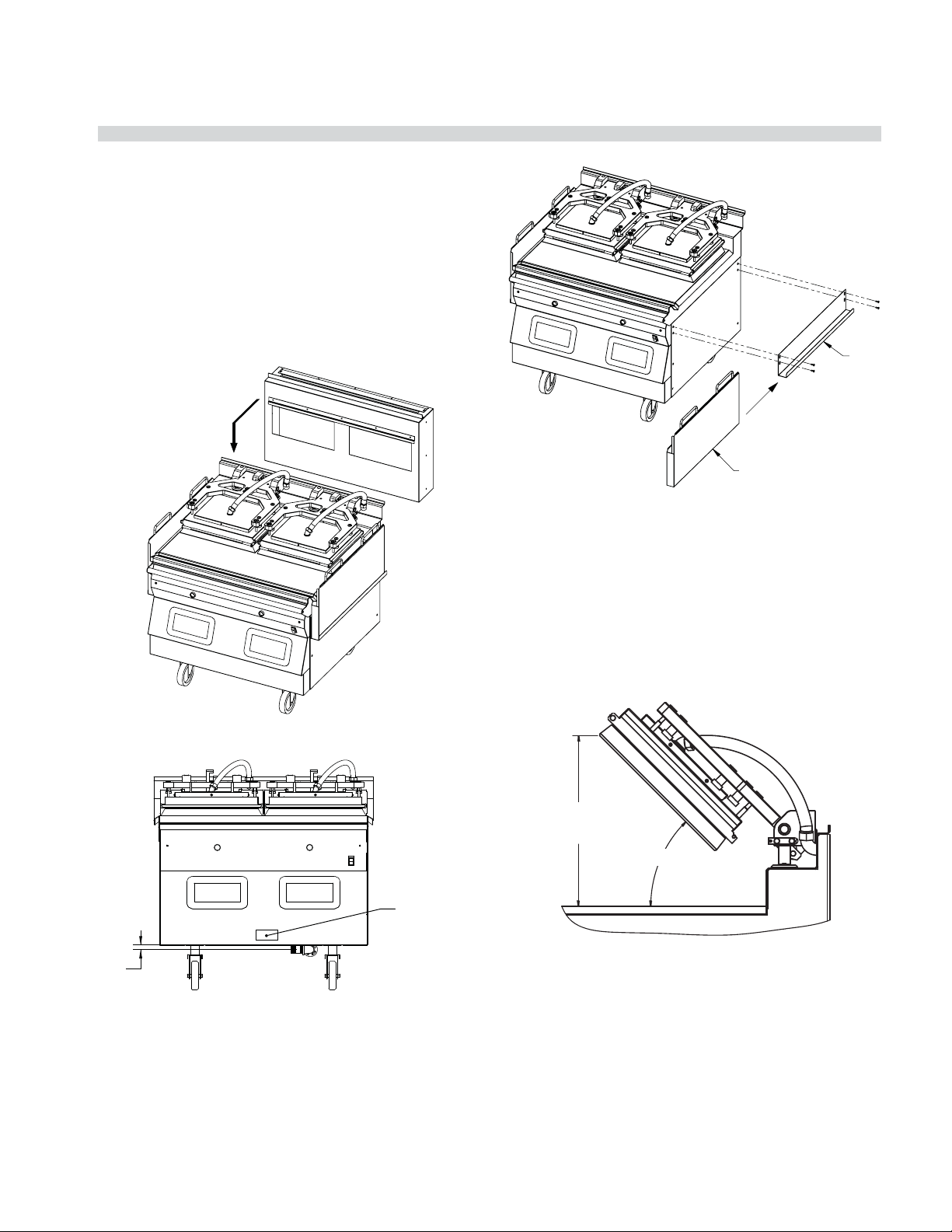
8. Install ue box to back of grill for single or double
platen (If required).
FOR GAS GRILLS ONLY
FLUE BOX CLIPS ON REAR LIP OF
GRILL & IS CENTERED SIDE TO SIDE
GREASE BUCKETS & RAILS NOT
SUPPLIED BY MANUFACTURER
GREASE BUCKET
RAIL
FLUE BOX IS NOT SUPPLIED
BY THE MANUFACTURER
9. Install grease bucket rails as shown below:
.750
ATTACH SHUT-OFF
STICKER IN THIS
LOCATION
10. Roll grill under hood. Grill must be level front to back,
side to side and diagonally. Adjust casters accordingly
to obtain nal level.
Hood Type & Platen Height
With the platens in the raised position, measure the height
from the front edge of the platen to the grill surface. If the
platen height is over 17” (431mm), it must be adjusted to
proper clearance by an authorized service agent.
17in
[431mm]
MAX
45°
LonWorks Information & Commissioning
To Activate the grill onto the Lonworks
network:
To enable the power line communications between the
grill and the Lonworks network the grill must rst be
commissioned onto the network.
PART #4527466 (12 Aug 2011) Page 19
Page 20

INSTALLATION/OPERATION & SERVICE MANUAL - 1&2 PLATEN GARLAND CLAMSHELL GRILLS WITH PRODUCT RECOGNITION
INSTALLATION & STARTUP (continued)
During the commissioning of a Grill onto a Lonworks
network the grill has to rst send a service pin request
message from the grill to the Lonworks server.
The grill sends this message by following the below
procedure on the front panel control of the grill.
1. Power up grill.
2. PRESS and HOLD the button for approximately 3
seconds. Controller will display previously selected
menu item and its corresponding item number.
3. PRESS the AND arrow buttons TOGETHER.
“CONFIGURE” will appear in the display.
4. PRESS the arrow button. “SERVICE” will appear in the
display. PRESS the button.
5. Press the arrow button 2X. “Lonworks Service” will
appear in the display.
6. PRESS the button.
7. Set option to “NO”. Wait 10 seconds. If the Lonworks
service state was already “ON” make sure this step is
done anyway.
8. Set option to “YES”. Within 10 seconds the network will
receive the Lonworks Service Pin Request.
After the grill service pin request has been sent the
Lonworks administrator will detect the service pin
message and assign an appropriate address to the grill to
enable communications.
Startup Procedure
This Garland 1&2-platen grill comes with a factory startup
at no additional charge. A startup is required to take
place BEFORE the unit is put into operation. It is the
end-user responsibility to schedule the startup with their
local Factory Authorized Service Agent, or notify Garland
Commercial Ranges at 1-800-427-6668 should you need
assistance scheduling.
A factory startup is a comprehensive grill check in which
a factory certi ed technician will document all nal
settings programmed in the controller once various other
performance checks are complete. The estimated time to
complete a startup is approximately 1.5 – 2 hours. Please
keep in mind this estimated time when scheduling the
startup. After hours or overtime is not covered under
warranty and will be billed at a charge which is the
di erence between the Garland Reimbursement rate and
the Factory Authorized Service Centers overtime charges.
A factory startup is necessary to start the warranty period.
The Authorized Service Center is required to complete
the paperwork during the startup process, and send it
to Garland Commercial Ranges for reimbursement. At
the time of receipt, Garland will start the warranty period
which will conclude at the end of 2 years.
After the Lonworks server has established this address
the communications will be activated by the Lonworks
administrator and the grill will start communicating on the
Long Network
PART #4527466 (12 Aug 2011)Page 20
Page 21
GARLAND CLAMSHELL GRILLS WITH PRODUCT RECOGNITION INSTALLATION/OPERATION & SERVICE MANUAL - 1&2 PLATEN
INSTALLATION & STARTUP (continued)
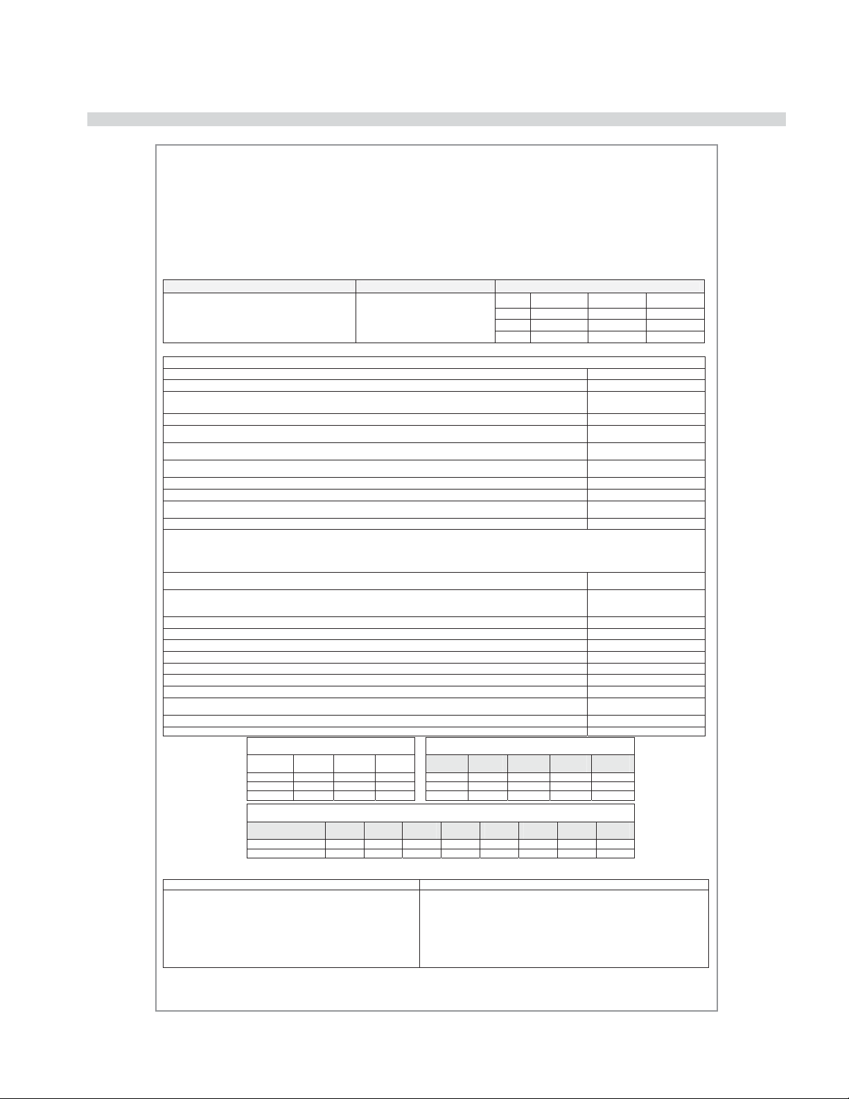
GARLAND CLAMSHELL GRILL START – UP FORM
ELECTRIC OR COMBINATION GAS / ELECTRIC
McDonald’s ___________ Certification ID # __________ Store #_____________ Start-up Date ___________________________
Address ____________________________ City ___________________________Model # ƑMWE3W | ƑMWG3W | ƑMWE2W | ƑMWG2W
Circle One
State / Province ______________________ Zip Code _______________________Serial # ________________________________
Ƒ United States Ƒ Canada Ƒ International (List Country) __________________Telephone # ____________________________
Actual Gas Type ____________
Matches Rating Plate? YES NO
1. To avoid personal injury or property damage,
2. Ensure grill is installed in the proper type of
3. Ensure flu restrictors are fully opened or removed. Flue Box Supplied by KES
Flu Restrictors located inside exhaust hood
4. Ensure bottom plate is leveled side to side / front to back / diagonally, in location, under hood. Adjust casters to attain level.
5. REMOVE GRILL FROM UNDER THE HOOD. Turn Power Switch ON, controller displays are active, Controller displays “OFF”.
All platen raises automatically?
6. Lower and raise Upper Platen and insure movement is smooth and continuous. Grease shafts accordingly with a FOOD GRADE
LUBRICANT.
7. If upper platen elevation requires lowered to allow for clearance of hood, lower upper limit switch. Refer to Operations &
Installation manual for platen heights.
8. Press the POWER ON button. Controller displays “PREHEAT - AM”, platen lowers. Heat indicator lights are AMBER?
9. Press the AM / PM key. This will allow the unit to heat to: Platen-425˚F(217˚C), Grill-350˚F(177˚C).
10. Grill enters SOAK mode (15:00 timer), counts down and upper platen auto calibrates at temperatures: Platen-425˚F(217˚C), Grill350˚F(177˚C)
11. Close valve hand le and verify the unit tries to ignite four (4) times. Unit locked out to Ignition Failure?
12. GAS PRESSURE CHECKS (if applicable):
Rated Incoming Pressure Natural Gas 6 – 14 Inches W.C. Actual Incoming __________________
Propane / Butane Gas 11 – 14 Inches W.C. Actual Incoming __________________
Rated Burner Pressure Natural Gas 3.5 Inches W.C. Actual Left ________ Center ________ Right _________
Propane / Butane Gas 3.5 Inches W.C. Actual Left ________ Center ________ Right _________
13. Check micro amp readin g to ensure operating micro amps ARE NO LESS THAN .8. Micro Amp reading should be
between .9 – 1.2.
14. Upon Completion of auto calibration, platen raised automatically, and display reads “READY”
If upon completion of auto calibration process, upper platen does not raise, i ndicate message on controller.
Check platen level and adjust reed switches. Cycle power and retry.
15. Select menu item “ 10:1 – CLAM”. Verify set temperature is reached and LED lights turn GREEN.
16. Initiate cook cycle by pushing the GR EEN PUSHBUTTON. Platen lowers, and timing cycle begins.
17. Ensure the stores pyrometer is accurate and calibrated using the ice bath method.
18. Perform PROBE CALIBRATION.
19. Perform Platen Ze roing procedure & Reed Switch Calibration in “LEVEL / REED SW” mode.
20. Platen performed Auto Calibration upon completion of reed switch calibration?
21. Lock down all cap s. Ensure that the lock nuts do not turn any of the adjuster nuts when tightening.
22. Assist or obtain as sistance with store personnel for Beef Integrity Testing, testing product 10:1 and 4:1 until desired internal
product temperatures are met.
23. Record cook times , gap settings, and any gap calibrations used to obtain beef integrity.
24. Record Calibra tion numbers below:
Problems / Special Circumstances / Damage:
Name: _________________________________________________________ Name: __________________________________________________________________
Service Agency: _________________________________________________
Sub Agent: (If Applicable) _________________________________________
Have you trained store personnel on the
operation of the grill?
Are you a factory certified technician?
Date of Certification
P/N 4521780 (7 Feb 11)
(MM/DD/YY)
(FOR USE IN MODEL MWE3W/MWG3W & MWE2W/MWG2W Series grills ONLY)
Located on Certification Sticker
Gas Type Electric / 3-phase Record Amps Per Line Each Contactor
Actual Input _______________
Ƒ 208 VAC Ƒ 380 VAC
Ƒ 220 VAC Ƒ 400 VAC
Ƒ 230 VAC Ƒ 415 VAC
Ƒ 240 VAC
MM / DD / YY
Left
Line 1
Line 2
Line 3
Center
If Applicable)
INSPECTION / OPERATIONAL CHECK
NOTE: CENTER PLATEN should not be checked if MWE2W / MWG2W
Check for Gas Leak
Gas Exhaust Hood
Product Cook Times
(MWE3W & MWG3W | MWE2W & MWG2W)
LEFT
10:1 LEFT
4:1 CENTER
ANGUS RIGHT
2 PLATEN PRC Grills
ONLY
LEFT
RIGHT
Submitted by: Accepted by:
CENTER
If Applicable
Front LT
Cal
YES / NO
YES / NO
through the entire gas line.
with the proper air draw.
Calibration numbers (from CALIBRATION MENU)
RIGHT
Calibration numbers (from CALIBRATION MENU)
Back LT
Cal
Back
MWE2W & MWG2W ONLY
Front RT
Cal
Have you been adequately informed of the operation of the grill, its uses and its general
operation? Ƒ YES | Ƒ NO – Indicate comments __________________________________
________________________________________________________________________
________________________________________________________________________
________________________________________________________________________
Back RT
Cal
Reed Cal
MWE3W & MWG3W ONLY
Front LT
Detect
Front
Reed Cal
Back LT
Detect
White Copy – Factory Yellow Copy – Service Agency Pick Copy – Customer
Ƒ COMPLETED – NO GAS LEAK
Ƒ
OK
Ƒ
OK
Ƒ
OK
Ƒ
OK
L
Ƒ
OK | C Ƒ OK | R Ƒ OK
L
Ƒ
OK | C Ƒ OK | R Ƒ OK
L
Ƒ
OK | C Ƒ OK | R Ƒ OK
L
Ƒ
OK | C Ƒ OK | R Ƒ OK
L
Ƒ
OK | C Ƒ OK | R Ƒ OK
L
Ƒ
OK | C Ƒ OK | R Ƒ OK
L
Ƒ
OK | C Ƒ OK | R Ƒ OK
Ƒ
OK
OK -
Ƒ
L / Ƒ C / Ƒ R
Check Platen Level
Check Reed Switch
L
Ƒ
OK | C Ƒ OK | R Ƒ OK
L
Ƒ
OK | C Ƒ OK | R Ƒ OK
Ƒ
OK
L
Ƒ
OK | C Ƒ OK | R Ƒ OK
L
Ƒ
OK | C Ƒ OK | R Ƒ OK
L
Ƒ
OK | C Ƒ OK | R Ƒ OK
L
Ƒ
OK | C Ƒ OK | R Ƒ OK
Ƒ
OK | C Ƒ OK | R Ƒ OK
L
L
Ƒ
OK | C Ƒ OK | R Ƒ OK
Back
Front RT
Detect
Front
Zero Cal
Back RT
Detect
Zero Cal
- Ƒ L / Ƒ C / Ƒ R
- Ƒ L / Ƒ C / Ƒ R
Right
PART #4527466 (12 Aug 2011) Page 21
Page 22
INSTALLATION/OPERATION & SERVICE MANUAL - 1&2 PLATEN GARLAND CLAMSHELL GRILLS WITH PRODUCT RECOGNITION
INSTALLATION & STARTUP (continued)
Setting the Proper Combustion Levels
Using the following procedure will ensure
that the proper O2, CO2, & CO levels are
reached. If you have any questions, please
contact 1-800-446-8367. Combustion level
checks and adjustments should only be
performed by a quali ed technicians
employed by a factory authorized service center.
1. Remove control panel and lower front panel. Set on
oor, leaving all connections in place.
2. The regulator comes set at 3.5” W.C (0.864 kPa) or 10.0”
W.C. (0.249kPa), depending on type of gas. Verify
pressure settings at the test spigot on each gas valve
and adjust the regulator as needed..
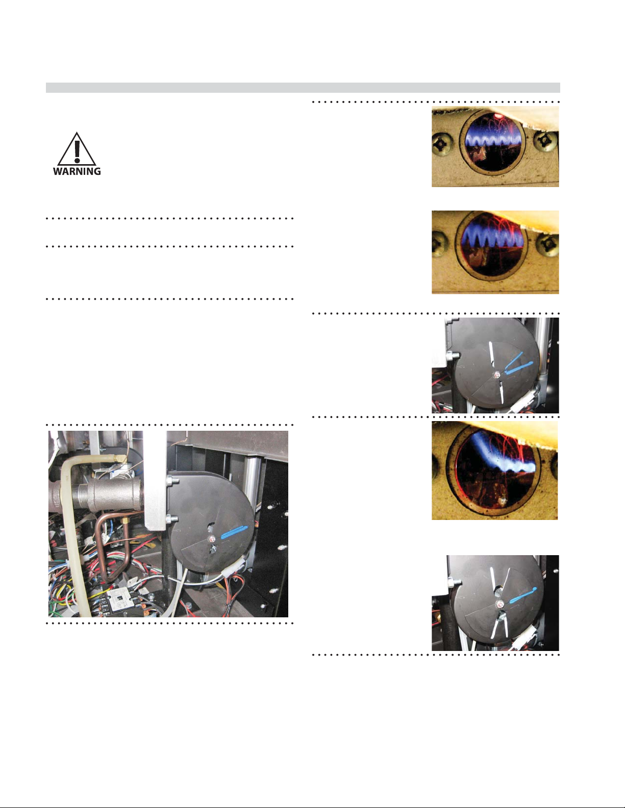
3. Slightly loosen nut holding butter y air shutter
adjuster on the combustion air blower connected to
the burner being adjusted just enough that it can be
rotated but will stay in place when force is removed.
Air shutter openings are factory set and marked with
a line on the blower face. Note if the air shutter has
been moved from this reference line. When marking
the blower face with reference lines in the following
steps, make them on the opposite side of where the
factory mark exists.
4. From a cold start, turn
on zone for the burner
being checked and
allow it to run for 1
minute to stabilize.
If the grill is already
preheated, add a load
to the surface to keep
burner operating for
several minutes. With
burner operating,
adjust the air shutter
to a more closed
position until the
ame begins to lift or
oat o the burner
surface.
5. Mark a line on the
blower face along the
edgwe of the shutter
from the air opening
to the end of the
butter y shutter. This
is the “low” point of
reference..
6. Rotate the air shutter
to a more open setting
until the ame loses
blue cone de nition
or begins to elongate
(approximately double
in height). Mark a
line on the blower
face along the shutter
from the air opening
to the end of the
butter y shutter. This
is the “high” point
of reference. If the
air shutter is at a
fully open position
before ame changes,
mark the line at this
position.
Good ame
Lifting ame with lack of air
Lifting ame with too much
air
PART #4527466 (12 Aug 2011)Page 22
Page 23

GARLAND CLAMSHELL GRILLS WITH PRODUCT RECOGNITION INSTALLATION/OPERATION & SERVICE MANUAL - 1&2 PLATEN
INSTALLATION & STARTUP (continued)
7. Draw a line joining the
endpoints of the low
and high reference
lines. At the midpoint
of this new line make
a mark.
8. Rotate air shutter at the midpoint mark and verify
that the ame is stable on the burner surface without
lifting or discoloration. If the ame is stable, tighten
the butter y nut..
9. If the ame is still abnormal, make another mark 1/16”
away from the butter y along the joining line and
rotate the butter y to this position. This will reduce
the air ow. Very y the ame stability and tighten
butter y nut.
PART #4527466 (12 Aug 2011) Page 23
Page 24

INSTALLATION/OPERATION & SERVICE MANUAL - 1&2 PLATEN GARLAND CLAMSHELL GRILLS WITH PRODUCT RECOGNITION
INSTALLATION OF RELEASE MATERIAL
The following are the procedures for installing the Release Material sheets on the upper platen on the Garland Clamshell
grill. The components shown below are included with your grill when purchased.
1. Slide release material rod through hemmed end of the
release material sheet.
HEMMED
LOOP
MATERIAL
ROD
RELEASE
MATERIAL
“Teon Sheet” available from your DC
Saint GobainėDC WRIN # 02174-003
TaconicėDC WRIN # 02174-000
2. Hook release material rod on brackets located at the
rear of the upper platen.
FRONT FLAP
WRAPPED
OVER RELEASE
MATERIAL BAR
AND CLIPPED
IN PLACE
LEFT & RIGHT
FLAPS
5. After securing the release sheet from the back of
the platen to the front, secure it to the left and right
sides of the platen. Wrap one side of the release sheet
material around the side of the platen. Place one (1)
locking clip over the sheet and press into place over
release material bar. Repeat this procedure for the
other side of the platen.
RELEASE
MATERIAL
CLIPS
UPPER PLATEN
(SIDE VIEW)
RELEASE
MATERIAL
MATERIAL
MATERIAL
ROD HOLDER
ROD
3. Holding the bottom of the release material sheet in
place, gently pull the sheet toward the front of the
platen, and wrap the front ap up and over the release
material bar on the front of the platen.
4. Place two (2) locking clips over release material sheet
and press into place over release material bar.
NOTE: Make sure release material is t smoothly along the
bottom surface of the upper platen.
WRAP & CLIP BOTH SIDES
5. Check alignment and tightness of release material
against upper platen.
Release material sheets should be replaced when:
• Product sticks to release material
• Carbon build-up causes problems in taste or
appearance.
• A tear in the release material sheet’s cooking area.
• Release material coating is worn o sheet.
NOTE: Rotate the release sheets on daily basis
PART #4527466 (12 Aug 2011)Page 24
Page 25
GARLAND CLAMSHELL GRILLS WITH PRODUCT RECOGNITION INSTALLATION/OPERATION & SERVICE MANUAL - 1&2 PLATEN
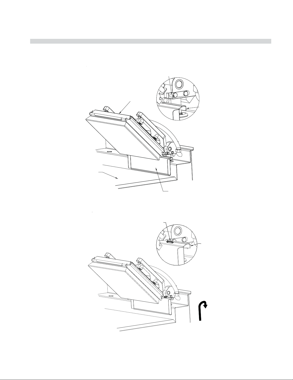
INSTALLATION OF SPLASH SHIELD
The following is the procedure for installing the Splash Shield on the rear of the upper platen arm assembly. The Splash
Shield is installed to protect the back splash from grease splashing during normal operating use of the grill.
*TWO PER UPPER PLATEN
STEP 1
UPPER
PLATEN
UPPER PLATEN
BLOCK PIN
(ONE ON EACH SIDE)
SPLASH SHIELD
HOOK FEATURE
STEP 2
SURFACE OF
GRILL PLATE
NOTE: SOME COMPONENTS OMITTED FOR CLARITY
UPPER PLATEN
BLOCK PIN
SPLASH
SHIELD
SPLASH SHIELD
HOOK FEATURE
SPLASH SHIELD HOOK FEATURE
UP AND ONTO UPPER PLATEN
BLOCK PIN IN THIS DIRECTION
(BOTH SIDES)
NOTE: SOME COMPONENTS OMITTED FOR CLARITY
PART #4527466 (12 Aug 2011) Page 25
Page 26
INSTALLATION/OPERATION & SERVICE MANUAL - 1&2 PLATEN GARLAND CLAMSHELL GRILLS WITH PRODUCT RECOGNITION
CLEANING & MAINTENANCE
McD
®
Hi-Temp Grill Cleaner
Nettoyant à chaud
pour grils
Limpiador de parrilla s
de alta temperatur a
CAUTION: May cause eye and skin
irritation. See precautionary and
KEEP OUT OF REACH OF CHILDREN
CUIDADO: Puede causar irritación
de los ojos y la piel. Véanse
las precauciones y los primeros
auxilios al reverso.
MANTENGASE FUERA DEL
ALCANCE DE LOS NIÑOS
AVIS : Peut irriter les yeux et la peau.
Voir précautions et premiers
soins au verso.
CONSERVER HORS DE LA
PORTÉE DES ENFANTS
®
3.6 oz (106 ml)
McD® Hi-Temp
Grill Cleaner
AUTO
AM
MAN
PM
1
KAY® Grill Cleaning Pad Holder
®
& KAY
Grill Cleaning Pad
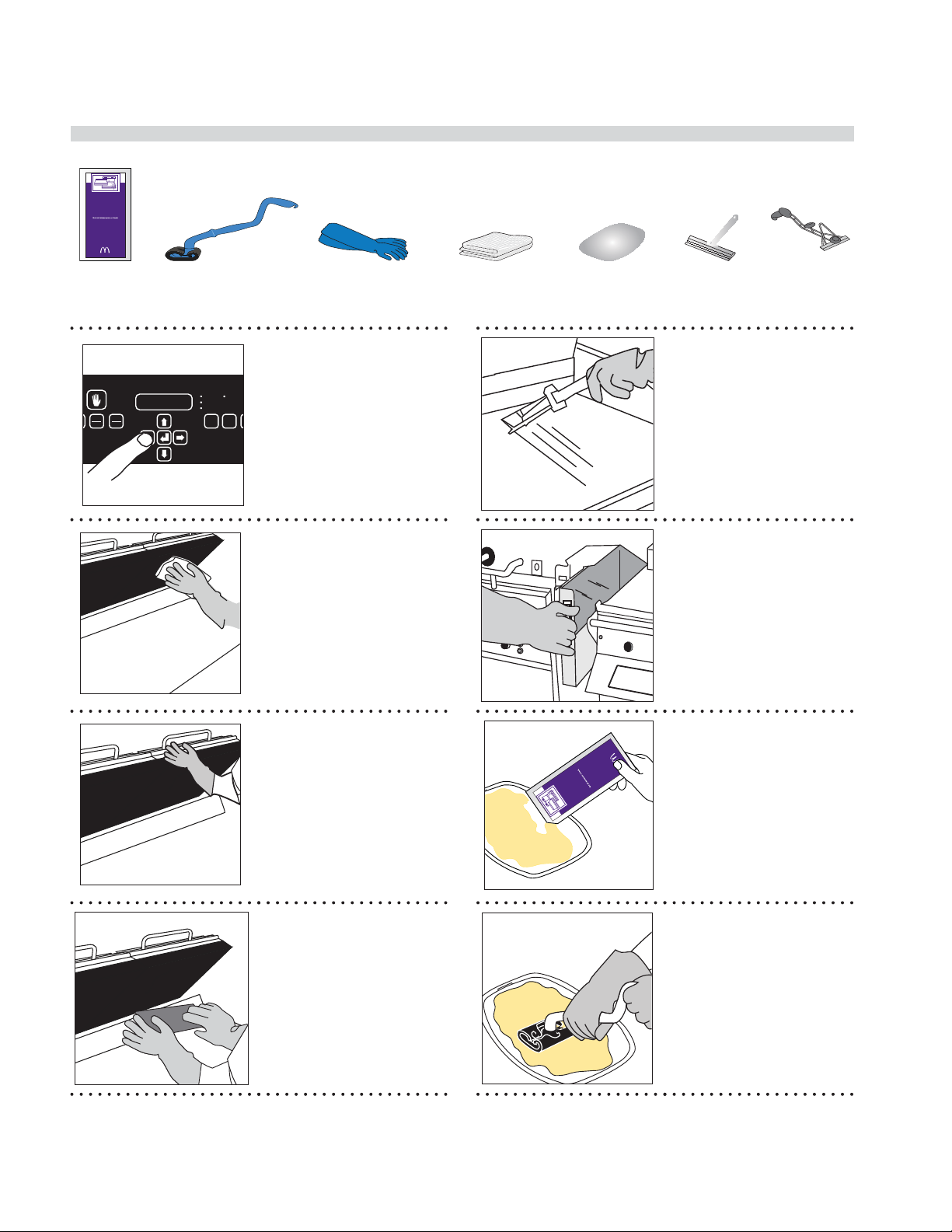
• Select Clean Mode.
P
• After turning grill OFF,
Heat-Resistant Gloves Clean, Sanitizer-Soaked
Once Clean Mode has
been reached turn
grill OFF.
platens can be controlled
by pressing green button
Grill Cloths
5
Lid
Grill Squeegee
Grill Scraper
• Scrape the lower grill
surface with the grill
scraper.
• Use grill squeegee to
push residual grease into
trough.
• Take grill scraper to the
3-compartment sink to
be washed and rinsed.
2
3
• Wipe the Release
Material® sheets with a
clean, sanitizer-soaked
grill cloth.
• Remove the locking
clips, bars, and release
sheets.
• Take the clips and bars to
the 3-compartment sink
to be washed and rinsed;
set aside.
• Set release sheets aside
on a at surface.
• If splash guards are
installed, detach
and take to the
3-compartment sink to
be washed and rinsed;
set aside.
• Empty and replace the
grease troughs.
6
LA
ANTS
la peau.
3.6 oz (106 ml)
DES ENF
meros
ions et premiers
i
les yeux et
UERA DEL
r
F
PORTÉE
soins au verso.
DE LOS NIÑOS
irritación
CONSERVER HORS DE
in
y los p
k
y and
F CHILDREN
a
s
oir précaut
ar
Peut irriter
ios al reverso.
V
:
H O
ALCANCE
ye and s
auxil
MANTENGASE
VIS
A
Puede causar
ecaution
r
p
las precauciones
de los ojos y la piel. Véanse
UT OF REAC
O
May cause e
CUIDADO:
ON:
KEEP
I
irritation. See
®
CAUT
pour grils
de alta temperatur
McD
Limpiador de parrilla
emp Grill Cleaner
Nettoyant à chaud
Hi-T
• Open one packet of McD
Hi-Temp Grill Cleaner
and empty the contents
into a lid or stainless
steel pan.
• Put on the heat-resistant
gloves.
7
• Dip the KAY Grill
Cleaning Pad Holder into
the grill cleaner.
4
8
PART #4527466 (12 Aug 2011)Page 26
Page 27

GARLAND CLAMSHELL GRILLS WITH PRODUCT RECOGNITION INSTALLATION/OPERATION & SERVICE MANUAL - 1&2 PLATEN
CLEANING & MAINTENANCE (continued)
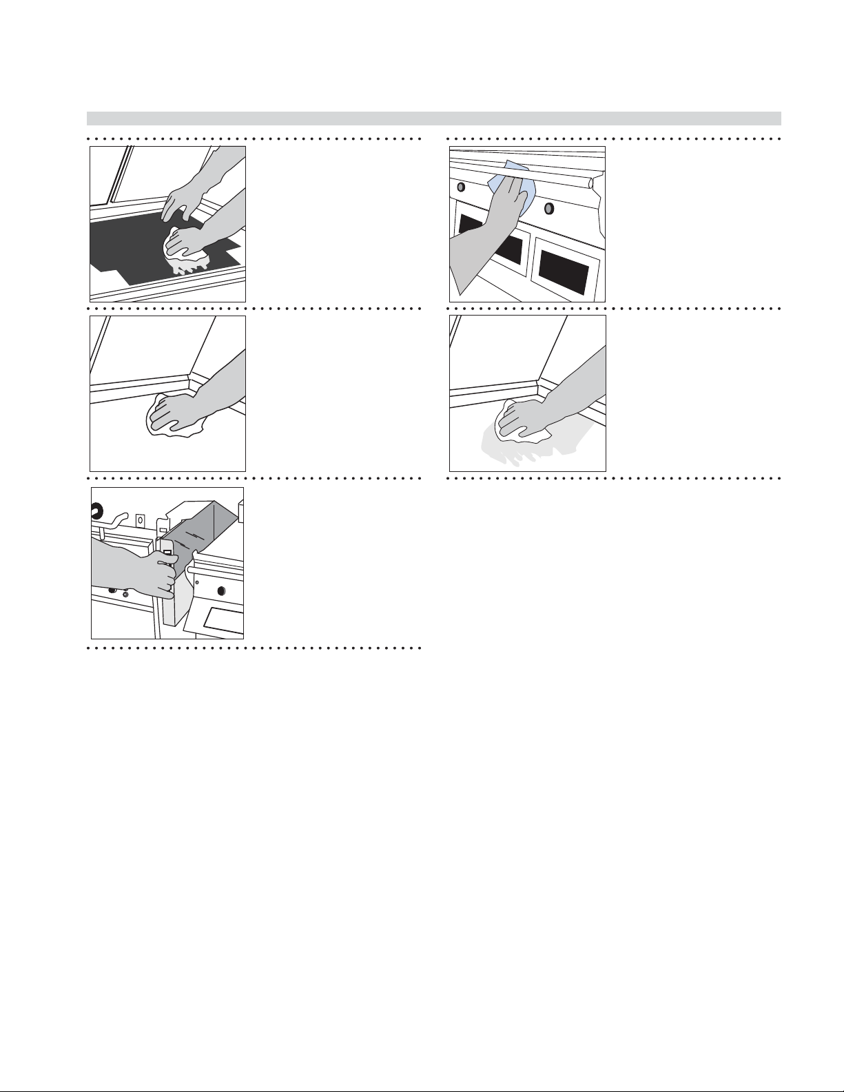
• (This step not required
• Apply McD Hi-Temp
Grill Cleaner to front
side of platens starting
from right platen to left
platen.
• DO NOT SCRUB
9
• Apply the grill cleaner to
platen surfaces starting
from right platen to left
platen.
• DO NOT SCRUB
14
on one platen version)
• Apply grill cleaner to
inner edges of the right
and left platens.
• DO NOT SCRUB
• Press green button to
raise right platen.
• Pour remaining McD HiTemp Grill Cleaner over
bottom grill surface.
10
11
12
• Apply the grill cleaner
to back side of platens
from right platen to left
platen.
• DO NOT SCRUB
• Apply the grill cleaner to
outer edges of right and
left platens.
• DO NOT SCRUB
15
• Spread the cleaner over
the entire lower grill
surface from front to
back using even strokes.
• DO NOT SCRUB
16
• Scrub front side of
platens from right platen
to left platen with KAY
Grill Cleaning Pad Holder
and Pad.
17
• (This step not required
on one platen version)
• Press green button to
lower right platen.
13
PART #4527466 (12 Aug 2011) Page 27
18
• Scrub at grill surfaces
starting from right platen
to left platen.
Page 28

INSTALLATION/OPERATION & SERVICE MANUAL - 1&2 PLATEN GARLAND CLAMSHELL GRILLS WITH PRODUCT RECOGNITION
CLEANING & MAINTENANCE (continued)
• Rinse front, side and
back of platen surfaces
with a clean, sanitizersoaked grill cloth,
starting from right to left
platens.
• (This step not required
on one platen version)
• Press the green button
to lower right platen,
rinse inner edges of both
platens; then, raise.
19
20
• Scrub back side of
platens from right platen
to left platen.
24
• Scrub outer edges of
right and left platens.
25
21
22
23
• (This step not required
on one platen version)
• Press green button to
lower right platen.
• (This step not required
on one platen version)
• Scrub inner edges of the
right and left platens.
• Press green button to
raise the right platen.
• Scrub lower grill surface.
• Wipe back of lower grill
with a clean, sanitizersoaked grill cloth.
26
• Pour a small amount of
lukewarm water on a
clean, sanitizer-soaked
grill cloth over the
bottom grill surface and
wipe o residue.
27
• Place upper platen
Release Material sheets
at on grill surface.
• Gently clean both sides
of the Release Material
sheets with the KAY Grill
Cleaning Pad Holder.
28
PART #4527466 (12 Aug 2011)Page 28
Page 29
GARLAND CLAMSHELL GRILLS WITH PRODUCT RECOGNITION INSTALLATION/OPERATION & SERVICE MANUAL - 1&2 PLATEN
CLEANING & MAINTENANCE (continued)
• Rinse both sides of the
29
Release Materialsheets
with a clean, sanitizersoaked grill cloth.
• Reinstall upper Release
Material sheets; secure in
place with bars and clips.
32
• Wipe remaining grill
surfaces with a clean,
sanitizer-soakedgrill
cloth.
30
31
• Wipe lower grill with a
clean,sanitizer-soaked
grill cloth. Repeat until
no visible soil remains.
• Empty, wash, rinse,
and replace the grease
troughs.
• Apply a thin coat of fresh
shortening to the lower
grill surface only.
33
PART #4527466 (12 Aug 2011) Page 29
Page 30

INSTALLATION/OPERATION & SERVICE MANUAL - 1&2 PLATEN GARLAND CLAMSHELL GRILLS WITH PRODUCT RECOGNITION
GRILL ACCESSORIES
Te on Wraparound kit
Description: Te on Sheet (Wraparound)
Part Number: 4527642
Quantity:
3
(1&2 platen only)
Description: Te on Wraparound Kit
Part Number: 4528083
Quantity:
1 - (Includes all Shown)
Description: Te on Rear Bar
Part Number: 4526436
Quantity:
1
Description: Te on Clip
Part Number: 4527294
Quantity:
4
PART #4527466 (12 Aug 2011)Page 30
Page 31

GARLAND CLAMSHELL GRILLS WITH PRODUCT RECOGNITION INSTALLATION/OPERATION & SERVICE MANUAL - 1&2 PLATEN
GRILL ACCESSORIES
BELOW POWER CORDS ARE RECOMMENDED
ONLY. CORDS APPY TO APPLICATION AND
ARE NOT STANDARD.
NEMA# L21-20P
Interlock Cord - 5Wire
(No Garland P/N) - *** Not supplied by Garland
NEMA# L15-30P
3Phase 4Wire 30 AMP Power Cord (Electric Grill ONLY)
(No Garland P/N) - *** Not supplied by Garland
Splash Shield
Item 4527646
Quick-Disconnect Gas Hose
Item 1591506
NEMA# 51-50P
3Phase 4Wire 50 AMP Power Cord (Electric Grill ONLY)
(No Garland P/N) - *** Not supplied by Garland
Te on Sheet (Not Wraparound)
Item 1799301
Te on rear rod
Item 4526436
Te on Clip
Item 4527294
PART #4527466 (12 Aug 2011) Page 31
Page 32

INSTALLATION/OPERATION & SERVICE MANUAL - 1&2 PLATEN GARLAND CLAMSHELL GRILLS WITH PRODUCT RECOGNITION
DESCRIPTION OF GRILL CONTROL
Right Arrow Button – In any mode, scrolls
forward through a list
Left Arrow Button – In any mode, scrolls
backward through a list
Enter Button – In the normal operating
mode, this button is not active. In the
Programming Mode, used to lock in the
values shown on the display.
Power Button – PRESSING and HOLDING the
Power button for 2 seconds will either turn
the controller on or o .
AM/PM Button – In normal operating mode,
toggles between the AM menu library and
the PM menu library.
AUTO/MAN Button – In normal operating
mode, toggles between Automatic Product
Recognition and Manual Cooking.
Up Arrow Button – In any mode, increases
the value of the ashing cursor character in
the display
Down Arrow Button – In any mode,
decreases the value of the ashing cursor
character in the display
Program Button – In the normal
operating mode, pressing and holding the
PROGRAM button for 3 seconds enters the
Programming Mode.
Temp Button – In the normal operating
mode, displays the set temperature and the
actual temperature.
Speed Key – In the normal operating mode,
used to change cook time. Also used to enter
Probe Calibration Mode. & Perform Auto
Forced Calibration
Standby Button – In the normal operating
mode, places the grill in Standby Mode.
POSSIBLE ERROR MESSAGES
GRILL PROBE ERROR – A grill temperature probe circuit error for temperature zone (Front, Middle, or Back) has occurred.
PLATEN PROBE ERROR – An upper platen temperature probe circuit error has occurred.
HEATER ERROR – Occurs when the controller does not detect a temperature rise in six (6) minutes.
HIGH TEMP – Occurs when the controller senses a temperature of 465˚ F (241˚ C).
CHECK REED SWITCH / USE FLAT COOK – One or more of the Reed Switches are out of adjustment. User will only be
able to cook FLAT menu items.
ERROR COMMS - A communications error has occured between the Motor Speed Control and the Main Control.
PLATEN NOT LEVEL – Occurs if the calibration di erence between the front and rear is greater than maximum allowance.
Product Recognition (Auto) and manual cooking is DISABLED. Flat Menu cooking is ONLY allowed.
CHECK PLATEN LEVEL – Occurs if the calibration di erence between the front and rear is greater than the minimum
allowance, but less than the maximum allowance. Product Recognition (Auto) is DISABLED. Perform
If CHECK PLATEN LEVEL is displayed, perform the following steps:
1. PRESS AND HOLD the and buttons for 3 seconds. The control will display AUTO GAP FORCE.
2. PRESS the button. “NO” will ash on the display. PRESS the button to change it to “YES.”
3. PRESS the button. The platen will immediately lower and reset its internal measurements. Upon completion,
the platen will rise. If the error message does not return continue operating normally. If the error message persists,
call your local authorized service agent.
PART #4527466 (12 Aug 2011)Page 32
Page 33

GARLAND CLAMSHELL GRILLS WITH PRODUCT RECOGNITION INSTALLATION/OPERATION & SERVICE MANUAL - 1&2 PLATEN
OPERATING PROCEDURES
General Overview:
The PRC grill control will allow for 2 functions, both
described in detail in the following sections
The “Normal Operating Mode”, also known as the Cook
Mode is the mode used during normal cooking. In the
normal operating mode, the operator can start a cook
cycle, cancel a cook cycle, view actual temperatures, scroll
to another menu item, and enter the Programming Mode.
The “Programming Mode” is the mode in which the
operator can program the controller’s various settings. To
enter the programming mode, PRESS and HOLD
There are currently 3 methods of cooking that can be
utilized with the 1 & 2 platens Garland clamshell:
Standard Cooking – This is the cook method that utilizes a
single gap setting for each menu item. The timer will count
down according to the selected menu item.
Multi Stage Cooking – This method of cooking utilizes 2
di erent gap settings during the cook cycle. The timer will
count down according to the selected menu item.
Product Recognition – The product recognition method
of cooking uses the magnetic switches mounted on the
upper platen arm assembly to determine the product
being cooked. Using the PR feature, the operator simply
selects the button on the controller. This will allow
the controller to know what product group to select
from. When a cook cycle is initiated, the platen will come
down and recognize the product being cooked. The
cook timer will count down according to the time set for
the recognized item. For more information on product
Recognition, see the next section; “Product Recognition.”
To turn the grill on:
The Main Power Switch – Controls power to the grill
and must be turned ON to start operation. The controller
displays will be active. Upon successful power up checks,
the controllers will displays “OFF”.
AM Operation – Release Material sheets MUST be ON at
this time and the grill surface should be free and clear of
carbon.
Once the PRC displays “OFF” press . The PRC will go to
PREHEAT mode and default to AM preheat temperatures.
To preheat to PM temperatures, press and hold .
AM PREHEAT PM PREHEAT
375˚F (190˚C) Upper Platen 425˚F (218˚C) Upper Platen
275˚F (135˚C) Grill 350˚F (177˚C) Grill
Upon reaching the AM or PM set temperature (whichever
is selected), the grill will stabilize in temperature for fteen
(15) minutes. Once this time has elapsed, the grill will
autocalibrate. Upon completion of autocalibration, the
upper platens will raise to there normal position, and the
PRC will display “READY”.
To Select a Menu item:
Scroll forward through the list of available menu items by
pressing repeatedly. Scroll backward through the list of
available menu items by pressing repeatedly.
Menu Item Library
The menu item library is loaded in the computer based
upon the setting programmed in [CONFIGURE]->[GRILL
REGION]. Each menu item consists of a function called
[DISPLAY ACTIVE]. The settings in this function (AM, PM,
AM/PM, No) determine what menu items are displayed
when the button is pressed.
Menu Item
10:1 - CLAM PM
4:1 - CLAM PM
STRIP BACON - CLAM AM/PM
SAUSAGE CLAM FZN AM
MCRIB - CLAM NO
STEAK - CLAM AM/PM
GRILLED CHICKEN - FLAT PM
FOLDED EGGS FLAT AM
ROUND EGGS - FLAT AM
CHICKEN FLAT BRD - FLAT NO
10:1 FLAT NO
4:1 - FLAT NO
MCRIB - FLAT NO
SAUSAGE FLAT FZN NO
HOTCAKES - FLAT NO
FOLDED EGGS CLAM AM
ROUND EGGS CLAM AM
3:1 ANGUS CLAM PM
MUSHROOMS CLAM AM/PM
OPT MENU 5 - CLAM NO
OPT MENU 6 - CLAM NO
OPT MENU 7 - CLAM NO
OPT MENU 1 - FLAT NO
OPT MENU 2 - FLAT NO
OPT MENU 3 - FLAT NO
OPT MENU 4 - FLAT NO
Display Active –
Default
PART #4527466 (12 Aug 2011) Page 33
Page 34

INSTALLATION/OPERATION & SERVICE MANUAL - 1&2 PLATEN GARLAND CLAMSHELL GRILLS WITH PRODUCT RECOGNITION
OPERATING PROCEDURES (continued)
Indicator Lights
The LED lights on the main control indicate the
temperature status of each zone.
Electric grills have (4) zones per section , TOP, (platen),
BACK GRILL, MIDDLE GRILL, and FRONT GRILL.
Gas grills have (2) zones per section , TOP, (platen),
and GRILL.
RED – The zone(s) is “TOO HOT” (more than 79˚F/43˚C over
set temperature) OR a heat zone failure has occurred.
AMBER – The zone(s) is calling for heat.
GREEN – The zone(s) is at or above set temperature, but
below 79˚F/43˚C over set temperature.
Standby Mode
To enter the standby mode:
1. Press the button. The upper platen will lower, and
the grill will maintain a set temperature of Upper platen
- 425˚ F (218˚C), Grill Surface - 350˚ F (177˚C).
To Exit the standby Mode:
1. Press the GREEN or ( GREEN & BLACK) pushbutton(s). The upper platen will raise.
To display the current temperatures:
1. Press the button and repeat for each zone to be
displayed:
1st key press – Front Set Point
2nd key press – Front Actual
3rd key press – Mid Set Point
4th key press – Mid Actual
5th key press – Back Set Point
6th key press – Back Actual
7th key press – Platen Set Point
8th key press – Platen Actual
2. Pressing and holding the button for ve (5) seconds
will display all of the current temperatures at once.
Breakfast In Manual mode
1. Select AM mode. Press and hold the button.
2. Select Manual mode. Press and hold the the button.
3. Select a product from the AM product library using the
or arrow buttons.
4. Following McDonalds procedures for the item selected,
load product on the grill.
5. Press the GREEN or ( GREEN & BLACK) pushbutton(s) to initiate a cook cycle.
6. Alarm will sound when the cook cycle is complete.
7. Remove product and clean grill to prepare for the next
cook cycle.
Lunch In Manual mode
Note: Switching from breakfast to lunch menu items will
take approximately 10 minutes to heat to the appropriate
temperatures.
1. Select PM mode. Press and hold the button.
2. Select Manual mode. Press and hold the button.
3. Select a product from the PM product library using the
or arrow buttons.
4. Following the below lay pattern, load product on the
grill.
5. Press the GREEN or ( GREEN & BLACK) pushbutton(s) to initiate a cook cycle.
6. Alarm will sound when the cook cycle is complete
7. Remove product and clean grill to prepare for next
cook cycle.
To Change The Cook Time for a Menu Item
1. Select AM or PM mode. Press and hold the button.
2. Select Manual mode. Press and hold the button.
3. Select a product using the or arrow buttons.
4. PRESS the button to display the cook time.
5. Use the and buttons to change the cook time.
6. The control will automatically default back to the
normal operating mode after 3 seconds.
Breakfast In Auto mode
1. Select AM mode. Press and hold the button.
2. Select Auto mode. Press and hold the button. The
control will display “AM / AUTOMATIC”
3. Following McDonalds procedures for the item selected,
load product on the grill.
4. Press the GREEN or ( GREEN & BLACK) pushbutton(s) to initiate a cook cycle. The platen will lower,
and recognize the product that has been loaded on the
grill.
5. Alarm will sound when the cook cycle is complete.
6. Remove product and clean grill to prepare for the next
cook cycle.
Page 34
Page 35

GARLAND CLAMSHELL GRILLS WITH PRODUCT RECOGNITION INSTALLATION/OPERATION & SERVICE MANUAL - 1&2 PLATEN
OPERATING PROCEDURES (continued)
Lunch In Auto mode
Note: Switching from breakfast to lunch menu items will
take approximately 10 minutes to heat to the appropriate
temperatures.
1. Select PM mode. Press and hold the button.
2. Select Auto mode. Press and hold the button. The
control will display “PM / AUTOMATIC.”
3. Following the lay patterns shown on the following
page, load product on the grill.
4. Press the GREEN or ( GREEN & BLACK) pushbutton(s) to initiate a cook cycle. The platen will lower,
and recognize the product that has been loaded on the
grill.
5. Alarm will sound when the cook cycle is complete
6. Remove product and clean grill to prepare for next
cook cycle.
Transition Cooking
Approximately 30 minutes before changing to the lunch
menu, perform the following:
1. PRESS the button (to display the upper platen
temperature).
2. Press the button.
3. The upper platen indicator will turn on. The upper
platen will heat to 425 degrees F (217 degrees C)
the platen will maintain this set temperature unless
another menu item is selected.
To Shutdown Grill
Turn Main Power Switch OFF to disable all burners. For
extended periods of shutdown, turn Main Power Switch
OFF, close and disconnect main gas and/or electrical
connections.
LONWORKS INFORMATION
LonWorks lets manufacturers and integrators create and implement control solutions for customers all over the world.
With LonWorks, you can embed intelligence and communications into any device with an electronic heartbeat, and then
network these devices so they can work together to sense, monitor, and control. Their embedded intelligence allows them
to work without a master controller or PC, and work with enterprise applications and other services.
This LonWorks gateway is a “Smart Equipment” networking solution for McDonalds. LonWorks allows us to use existing
power lines to transmit the data rather than the use of Ethernet cabling. The LonWorks gateway will collect information
from the grill and transmit it into a computer elsewhere. Capable and authorized users will be able to collect this
information and monitor the data from a centralized location. LonWorks enabled or smart equipment will have not only
the capability of being monitored, but programmed and set up as well.
PATTY PLACEMENT
This procedure for placement of meat products on the clamshell grill must be followed exactly. Place patties on the lower
grill plate 2 at a time, from front-to-back, and right-to-left, positioned as shown in the diagrams below. (Each square
represents one cooking lane; the area beneath one upper platen.)
When cooking is complete, the upper platen will raise automatically. Immediately after the platen raises, season the
meat, (if applicable), then remove the patties in the same order they were loaded one at a time. It is important that the
unload sequence is identical to the load sequence.
3
2
222
1
1
1
1
1
1
3
222
2
11
3
11
3
3
2
2
4
1
10:1 ONLY
NOTE: Patty placement procedure may vary outside of North America. Please consult your local McDonald’s management.
3
3
2
4
4
2
111
PART #4527466 (12 Aug 2011) Page 35
Page 36

INSTALLATION/OPERATION & SERVICE MANUAL - 1&2 PLATEN GARLAND CLAMSHELL GRILLS WITH PRODUCT RECOGNITION
PRODUCT RECOGNITION
This Garland Clamshell grill is equipped with Product Recognition Controls (PRC). This new technology allows the user to
simply start a cook cycle WITHOUT having to select a speci c menu item. The PRC will recognize the product thickness
by utilizing switches inside the upper platen and the magnets mounted on the platen arms. Once the PRC calculates
the thickness of the product that’s been loaded, it will look up product from the product range library (below), and
automatically select that product.
MENU ITEM MIN GAP MAX GAP
Breakfast Library Recommended Ranges
Strip Bacon .100 .130
Sausage Clam .210 .405
Steak Clam .430 .480
MENU ITEM MIN GAP MAX GAP
Lunch Library Recommended Ranges
10:1 Clam .160 .345
4:1 Clam .365 .499
3:1 Angus Clam .500 .880
Strip Bacon .100 .130
COMMON PRODUCT RECOGNITION ISSUES
Product Recognition Errors can appear in 2 ways:
1. After initiating cook cycle, the controller displays “PRODUCT NOT RECOGNIZED - NO RECIPE FOUND”.
2. The controller displays the incorrect product for the product that was layed on the grill.
In both cases, the most common reasons for these 2 issues are as follows:
Overlapping Product
- Ensure that you do
OVERLAPPING
PRODUCT
not have any patties
overlapping when you lay
product. This will fool the
controller into thinking
that there is much thicker
product on the grill than
there is
Platen makes contact
with Chicken Ring -
Always make sure that the
chicken ring is clear of the
adjacent platen prior to
initiating a cook cycle.
Auto calibation done
Wrinkled or Worn Te on
Sheet - Ensure that the
te on sheet is installed
and/or wrapped correctly
to platen. A loose, worn,
or te on sheet with
tears and/or scratches
can e ect product
recognition.
with carbon build up or
product residue on grill
surface - Ensure that the
grill surface is free of any
carbon build up. Debris
on the grill surface during
auto calbration will cause
the control to mark
the location of the grill
surface incorrectly.
In any of the cases as outlined above or in any other event, perform an Forced Auto Calibration to reset the upper platen
distance to the grill surface. Prior to performing a Forced Auto Calibration, be sure to:
1. Make sure the upper platen is free and clear of any carbon build up or debris.
2. Ensure that the grill surface is scraped and cleaned.
3. Te on sheet should not be worn and be t to the upper platen tightly.
Perform a Forced Auto Calibration routine as indicated in section “PRODUCT RECOGNITION”, “TO PERFORM FORCED AUTO
CALIBRATION”.
PART #4527466 (12 Aug 2011)Page 36
Page 37

GARLAND CLAMSHELL GRILLS WITH PRODUCT RECOGNITION INSTALLATION/OPERATION & SERVICE MANUAL - 1&2 PLATEN
BEEF INTEGRITY
As shown in the previous page, lay product on the grill in
the manner re ected. Product internal temperatures are
taken on the corner patties.
KEY NOTES:
- Full runs are always required when performing food
safety
- Target removal times refer to menu items chart.
- Seasoning the patties must be done prior to removing
The product from the grill.
10:1 Patties - Remove in 2 stacks of 4; Probe in center
of corner patties (1, 3, 7, 8).
Step 1: Using a
store calibrated
pyrometer, probe
3
3
3
3
the #1 patty (front
right corner) in the
center of the patty.
Step 2: Using a
store calibrated
pyrometer, probe
the #3 patty (rear
right corner) in the
center of the patty.
Step 3: Using a
store calibrated
pyrometer, probe
the #7 patty (front
left corner) in the
center of the patty.
Step 4: Using a
store calibrated
pyrometer, probe
the #8 patty (left
rear corner) in the
center of the patty.
4:1 Patties - Remove in 3 stacks of 2; Probe in center
of corner patties (1, 2, 5, 6)
Step 1: Using a
store calibrated
pyrometer, probe
5
3
1
the #1 patty (front
right corner) in the
center of the patty.
Step 2: Using a
store calibrated
pyrometer, probe
the #2 patty (rear
right corner) in the
center of the patty.
Step 3: Using a
store calibrated
pyrometer, probe
the #5 patty (front
left corner) in the
center of the patty.
Cooking grilled chicken utilizes various functions
and settings within the controller to ensure proper
temperature and integrity.
The use of a “Too Cool Flag” is programmed under Menu
Item programming. The Too Cool Flag should be set to “ON”
in Grilled Chicken & Mushrooms ONLY. In all remaining
5
5
3
3
1
1
menu items, the “TOO COOL FLAG” should be turned o .
The “Too Cool Flag” is a function in the control that allows
the grill operator to continue to cook approximately 1
additional run of product should the grill be in a “TOO
COOL” state prior to the start of a cook cycle, or at the end
of a cook cycle.
5
3
1
Step 4: Using a
store calibrated
pyrometer, probe
the #6 patty (left
rear corner) in the
center of the patty.
PART #4527466 (12 Aug 2011) Page 37
Page 38

INSTALLATION/OPERATION & SERVICE MANUAL - 1&2 PLATEN GARLAND CLAMSHELL GRILLS WITH PRODUCT RECOGNITION
PROGRAM LOGIC TREE; PRODUCT MENUS
Press & Hold
(3 seconds)
Menu
Item Displayed
RIGHT or LEFT arrow buttons
Scroll Menu Items
Scroll
Forward
Product
Library
Select Menu Item
Scroll
Backward
CLAM MENU ITEMS FLAT MENU ITEMS
Product Product
Display Active
Grill Set Point
Platen Set Point
Instant On Time
Remove In Time
Multi Stage 1 Time
Multi Stage 2 Time
Multi Stage 3 Time
Remove Alarm
Gap Setting
Display Active
Grill Set Point
Platen Set Point
Instant On Time
Remove In Time
Remove Alarm
Flip Time
Flip Alarm
Sear Time
Sear Alarm
Gap Mul/PR Start
Gap Multi Stage 1
Gap Multi Stage 2
Gap Multi Stage 3
Must Remove Time
Toast Buns Time
Toast Buns Alarm
Too Cool Flag
Scroll
Backward
Must Remove Time
Toast Buns Time
Toast Buns Alarm
Too Cool Flag
Scroll
Backward
PART #4527466 (12 Aug 2011)Page 38
Page 39

GARLAND CLAMSHELL GRILLS WITH PRODUCT RECOGNITION INSTALLATION/OPERATION & SERVICE MANUAL - 1&2 PLATEN
PROGRAM LOGIC TREE; SYSTEM MENUS
Press & Hold
P
(3 seconds)
Scroll
Forward
Menu Item Displayed
RIGHT or LEFT arrow buttons
Scroll Menu Items
Product
Library
Select Menu Item
Press & Hold
Simultaneously
AM Product Rec
Forward
Strip Bacon Min
Strip Bacon Max
Sausage Clam Min
Sausage Clam Max
Steak Clam Min
Steak Clam Max
Opt Menu 1 Min
Opt Menu 1 Max
Opt Menu 2 Min
Opt Menu 2 Max
1x
2x
3x
4x
5x
6x
7x
8x
9x
10x
Backward
Diagnostic
Forward
DateCode
Serial Number
Part Number
App Version
CLM1 Version
CLM2 Version
Audio Version
Motor Version
Ambient 1
Ambient 2
Ambient 3
Top Probe
Grill Probe F
Grill Probe M
Grill Probe B
Grill External Probe
PR Front Detect
PR Back Detect
PR T able Value
1x
2x
3x
4x
5x
6x
7x
8x
9x
10x
11x
12x
13x
14x
15x
16x
17x
18x
19x
Backward
Scroll
Backward
3x
5x
4x
PM Product Rec
6x
Temperature Units
Time Unit
Key Chirp
Audible
Audio Volume
Reload Defaults
Multi Gap (Yes/No)
Audible Select
Auto Mode Enable
Prod Rec Timeout
Heater ErrTimer
Too Cool Lo Lmt
Service
Forward
1x
2x
3x
4x
5x
6x
7x
8x
9x
10x
11x
12x
Backward
Forward
1x
Strip Bacon Min
2x
Strip Bacon Max
3x
10:1 Clam Min
4x
10:1 Clam Max
5x
4:1 Clam Min
6x
4:1 Clam Max
7x
Steak Clam Min
8x
Steak Clam Max
9x
McRib Clam Min
10x
McRib Clam Max
11x
Angus 3:1 C Min
12x
Angus 3:1 C Max
13x
Mushrooms C Min
14x
Mushrooms C Max
15x
Opt Menu 5 Min
16x
Opt Menu 5 Max
Backward
Forward
1x
Encoder Counts
2x
Motor Status
3x
Switch Status
4x
Start up Rate
5x
Buss Voltage
6x
Motor Max Speed
7x
Motor Revision
8x
Motor Error
9x
Lonworks Service
Backward
Setup
1x
2x
Configure
Calibration
Forward
1x
Grill Type
2x
Platen Enabled
3x
Grill Region
4x
Time Then Alarm
5x
Cook Zone
6x
More Multigap
7x
Auto Standby Timer
8x
Auto Standby Delay
Backward
Forward
1x
Level / Reed Sw.
2x
Auto Gap Force
3x
Probe Cal
4x
Gap Calibration
5x
Reed Sw. Min
6x
Reed Sw. Max
7x
Delta Spd Err
8x
Pivot End Mills
9x
Show Reed Data
10x
Front Reed Cal
11x
Back Reed Cal
12x
F Zero Cal
13x
B Zero Cal
14x
F Arm Offset_Min
15x
Cal Delta Percent
Backward
PART #4527466 (12 Aug 2011) Page 39
Page 40

INSTALLATION/OPERATION & SERVICE MANUAL - 1&2 PLATEN GARLAND CLAMSHELL GRILLS WITH PRODUCT RECOGNITION
CONTROL PROGRAMMING
Programming Modes; System Setup
To Change the Temperature Display Units
(Fahrenheit / Celcius)
The temperature display units (F or C) will change
the way a temperature is displayed on the controller
(F – Fahrenheit, C – Celcius)
1. With the controller display ON and either displaying
the current menu item or displaying “OFF”, PRESS and
HOLD the button for approximately 3 seconds.
Controller will display previously selected menu item
and its corresponding item number OR “Standby /
Menu Item”.
2. PRESS the AND arrow buttons TOGETHER.
“CONFIGURE” will appear in the display.
3. PRESS the arrow button. “Setup” will appear in the
display
4. PRESS the button. “Temperature Unit” will appear in
the display.
5. PRESS the button. The currently set temperature
unit will ash.
6. PRESS the OR arrow buttons to change the
ashing temperature unit.
7. PRESS the button to save the new setting.
8. PRESS THE 2X to exit the program mode.
To Change the Time Display Units
Changing the Time Display Units will change the way
timing cycles are displayed on the controller.
1. With the controller display ON and either displaying
the current menu item or displaying “OFF”, PRESS and
HOLD the button for approximately 3 seconds.
Controller will display previously selected menu item
and its corresponding item number OR “Standby /
Menu Item”.
2. PRESS the AND arrow buttons TOGETHER.
“CONFIGURE” will appear in the display.
3. PRESS the arrow button. “Setup” will appear in the
display.
4. PRESS the button. “Temperature Unit” will appear in
the display.
5. PRESS the 1X. “Time Unit” will appear in the display.
6. PRESS the button. The current time unit will ash.
7. PRESS the OR arrow buttons to change the
ashing time unit.
For a complete listing of setup functions and their
options, see section titled “FUNCTION OPTIONS;
SYSTEM MENUS”.
8. PRESS the button to save the new setting
9. PRESS THE 2X to exit the program mode.
To change the Key Chirp (Yes / No)
Changing the Key Chirp On or O will either turn on or o
the sound of the controller when a button is pressed.
1. With the controller display ON and either displaying
the current menu item or displaying “OFF”, PRESS and
HOLD the button for approximately 3 seconds.
Controller will display previously selected menu item
and its corresponding item number OR “Standby /
Menu Item”.
2. PRESS the AND arrow buttons TOGETHER.
“CONFIGURE” will appear in the display.
3. PRESS the arrow button. “Setup” will appear in the
display
4. PRESS the button. “Temperature Unit” will appear in
the display.
5. PRESS the repeatedly until “Key Chirp” appears in the
display.
6. PRESS the button. The currently set Key Chirp will
ash.
7. PRESS the OR arrow buttons to change the
ashing “YES” or “NO”
8. PRESS the button to save the new setting.
9. PRESS THE 2X to exit the program mode.
To change the Audible
Changing the Audible Sound will change the way the
controller sounds when a timing cycle has completed its
countdown.
1. With the controller display ON and either displaying
the current menu item or displaying “OFF”, PRESS and
HOLD the button for approximately 3 seconds.
Controller will display previously selected menu item
and its corresponding item number OR “Standby /
Menu Item”.
2. PRESS the AND arrow buttons TOGETHER.
“CONFIGURE” will appear in the display.
3. PRESS the arrow button. “Setup” will appear in the
display
4. PRESS the button. “Temperature Unit” will appear in
the display.
5. PRESS the repeatedly until “Audible” appears in the
display.
PART #4527466 (12 Aug 2011)Page 40
Page 41

GARLAND CLAMSHELL GRILLS WITH PRODUCT RECOGNITION INSTALLATION/OPERATION & SERVICE MANUAL - 1&2 PLATEN
CONTROL PROGRAMMING (continued)
6. PRESS the button. The currently set Audible will
ash.
7. PRESS the OR arrow buttons to change the
ashing audible options.
For a complete listing of setup functions and their
options, see section titled “FUNCTION OPTIONS;
SYSTEM MENUS”.
8. PRESS the button to save the current setting.
9. PRESS THE 2X to exit the program mode.
Programming Modes; Menu Items
To change the name of an existing menu item
1. Using the or button, select the menu item that
requires a name change.
2. PRESS and HOLD the button for approximately 3
seconds. Controller will display previously selected
menu item and its corresponding item number.
3. PRESS and HOLD the button.
4. To spell out the product name:
a. Use the or arrow buttons to scroll through
the character library.
Character Library:
space ! “ # $ % & ‘ ( ) * + , - . / 0 1 2 3 4 5 6 7 8 9 : ; < = > ? @ A B C D E F G H
I J K L M N O P Q R S T U V W X Y Z [ \ ] ^ _ ` a b c d e f g h i j k l m n o p q r
s t u v w x y z
b. PRESS or to scroll right or left.
c. PRESS the button to save the new menu item
name.
5. PRESS the 2X to exit and return to normal operating
mode.
To activate / deactivate a menu item in the Normal
Operating mode library, or change its day-part
(Defaults are listed in section “OPERATING PROCEDURES”)
1. PRESS and HOLD the button for approximately 3
seconds. Controller will display previously selected
menu item and its corresponding item number.
2. Using the or arrow buttons, select the menu item
that requires activation / deactivation.
3. PRESS the button. The controller will display
“Product”. The menu item will ash.
4. PRESS the or arrow buttons until “Display Active”
is displayed on the controller.
5. PRESS the button. The current setting will ash.
6. PRESS the or button to select a di erent setting.
7. PRESS the button to save the new setting.
8. PRESS the 2X to exit and return to normal operating
mode.
To change the grill surface set point temperature
NOTE: Grill temperature set points are preset in the controller to the
currently required standard. You should not change this set point to
any temperature other than what is shown in section “OPERATING
PROCEDURES”
1. Using the or arrow buttons, select the menu item
that requires a temperature change.
2. PRESS and HOLD the button for approximately 3
seconds. Controller will display previously selected
menu item and its corresponding item number.
3. PRESS the button. The controller will display
“Product”.
4. PRESS the or arrow buttons until “Grill SetPt” is
displayed on the controller.
5. PRESS the button. The current grill set temperature
will begin to ash.
6. Using the or button, change the temperature set
point to the new desired temperature.
7. PRESS the
button to save the new temperature set
point.
8. PRESS the 2X to exit and return to normal operating
mode.
PART #4527466 (12 Aug 2011) Page 41
Page 42

INSTALLATION/OPERATION & SERVICE MANUAL - 1&2 PLATEN GARLAND CLAMSHELL GRILLS WITH PRODUCT RECOGNITION
CONTROL PROGRAMMING (continued)
To change the grill upper platen set point temperature
NOTE: Grill temperature set points are preset in the controller to the
currently required standard. You should not change this set point to any
temperature other than what is shown in section “OPERATING
PROCEDURES”.
1. Using the or button, select the menu item that
requires a temperature change.
2. PRESS and HOLD the button for approximately 3
seconds. Controller will display previously selected
menu item and its corresponding item number.
3. PRESS the button. The controller will display
“Product”.
4. PRESS the or button until “Platen SetPt” is
displayed on the controller.
5. PRESS the button. The “PLATEN SET POINT” will
begin to ash.
6. Using the or button, change the temperature set
point to the new desired temperature.
7. PRESS the button to save the new temperature.
8. PRESS the 2X to return to normal operating mode.
To Change the MUST REMOVE IN time
1. Using the or button, select the menu item that
requires a cook time change.
2. PRESS and HOLD the button for approximately 3
seconds. Controller will display previously selected
menu item and its corresponding item number.
3. PRESS the button. The controller will display
“Product”.
4. PRESS the or button until “Must Remove In” is
displayed on the controller.
5. PRESS the button. The seconds will begin to ash.
6. Using the or arrow buttons to change the Must
Remove In time to the new desired time.
7. PRESS the button to save the new time.
8. PRESS the 2X to return to normal operating mode.
To Change the Toast Buns time
1. Using the or button, select the menu item that
requires a cook time change.
2. PRESS and HOLD the button for approximately 3
seconds. Controller will display previously selected
menu item and its corresponding item number.
3. PRESS the button. The controller will display
“Product”.
4. PRESS the or button until “Toast Buns Time” is
displayed on the controller.
5. PRESS the button. The seconds will begin to ash.
6. Using the or button, change the Toast Buns Time
to the new desired time.
7. PRESS the button to save the new time.
8. PRESS the 2X to exit and return to normal operating
mode.
To Change the Toast Buns Alarm (Auto / Manual)
1. Using the or arrow buttons, select the menu item
that requires a cook time change.
2. PRESS and HOLD the button for approximately 3
seconds. Controller will display previously selected
menu item and its corresponding item number.
3. PRESS the button. The controller will display
“Product”.
4. PRESS the or button until “Toast Buns Alarm” is
displayed on the controller.
5. PRESS the button. The “AUTO” or “MANUAL” will
begin to ash.
6. Using the or arrow buttons to change the
“MANUAL” to “AUTO” or “AUTO” to “MANUAL”.
7. PRESS the button to save the new setting.
8. PRESS the 2X to exit and return to normal operating
mode.
PART #4527466 (12 Aug 2011)Page 42
Page 43

GARLAND CLAMSHELL GRILLS WITH PRODUCT RECOGNITION INSTALLATION/OPERATION & SERVICE MANUAL - 1&2 PLATEN
CONTROL PROGRAMMING (continued)
To Add NEW Menu Items
The following programming instructions serves as a GUIDE for
programming the basic settings for CLAM menu items.
1. PRESS and HOLD the button for approximately 3
seconds. Controller will display previously selected
menu item and its corresponding item number.
2. PRESS the or button until “Opt menu # - CLAM” is
displayed on the controller.
3. PRESS the button. The controller will display
“PRODUCT”
4. PRESS and HOLD the button. The currently select
menu item name will begin to ash.
5. To spell out the product name:
a. Use the or arrow buttons to scroll through
the character library.
b. PRESS or to scroll right or left.
c. PRESS the button to save the new menu item
name.
6. PRESS the button. “Display Active” will be displayed.
7. PRESS the button. “NO” will begin to ash.
8. PRESS the button. “NO” will change to “YES”.
9. PRESS the button to save the new setting.
10. PRESS the button. “GRILL SETPT” will be displayed.
11. PRESS the button. The temperature will begin to
ash.
12. Using the or button, change the temperature set
point to the new desired temperature.
13. PRESS the button to save the new temperature set
point.
14. PRESS the button. “PLATSETPT” will be displayed.
15. PRESS the button. The temperature will begin to
ash.
16. Using the or button, change the temperature set
point to the new desired temperature.
17. PRESS the button to save the new temperature set
point.
18. PRESS the button until “GAP MULTI/PR START”
appears in the display.
19. PRESS the button. The gap setting will begin to
ash.
20. Using the and DOWN button, change the gap
setting to the desired setting.
21. PRESS the button to save the new gap setting.
22. PRESS the button 2X to exit and return to the normal
operating mode.
To Restore Factory Defaults for All Product Menu Items
1. With the controller display ON and either displaying the
current menu item or displaying “OFF,” PRESS and HOLD
the button for approximately 3 seconds. Controller
will display previously selected menu item and its
corresponding item number OR “Standby / Menu Item.”
2. PRESS the AND arrow buttons TOGETHER.
“CONFIGURE” will appear in the display.
3. PRESS the arrow button. “Setup” will appear in the
display
4. PRESS the button. “Temperature Unit” will appear in
the display.
5. PRESS the button 6x. The controller will display
“Reload Defaults – NO.”
6. PRESS the button. “NO” will begin to ash.
7. PRESS the button. “NO” will change to “YES”.
8. PRESS the button. The system will Reload the MENU
items to factory default settings.
9. Wait 15-20 seconds. The control then automatically
returns to OFF mode.
To Restore Factory Defaults for All Functions
1. Ensure the main power is turned o by turning the
main power switch to the OFF mode.
2. PRESS the AND arrow buttons TOGETHER, while
cycling main power ON with the main power switch.
The control will display “PASSWORD”
3. Within 3-5 seconds, press the following keys in this
sequence:
4. Upon successful completion, the controller will display
FULL DEFAULTS
5. Wait 15-20 seconds. The control then automatically
returns to OFF mode.
PART #4527466 (12 Aug 2011) Page 43
Page 44

INSTALLATION/OPERATION & SERVICE MANUAL - 1&2 PLATEN GARLAND CLAMSHELL GRILLS WITH PRODUCT RECOGNITION
PROBE CALIBRATION
Monthly Calibration of Grill Temperature Zones
Tools: Digital Pyrometer with Surface Probe
Warning: PERSONAL INJURY FROM BURNS MAY RESULT
WHEN COMING IN CONTACT WITH HOT COOKING
SURFACES.
NOTE: Probe Calibration of grills is done with release
material sheets “OFF”.
PLEASE FOLLOW THESE INSTRUCTIONS EXACTLY
AS THEY APPEAR BELOW:
1. The upper platens and lower grill plate should be at
operating temperatures to perform this calibration
procedure. Press the or button to select a
“CLAM” operation and allow the grill to reach the set
temperature and stabilize, (approximately 30 minutes).
2. PRESS and HOLD the button for approximately
3 seconds, or until the controller will display:
“PROBE CAL”.
3. PRESS the button to display the rst temperature
zone to be calibrated. The rst zone to be calibrated is
“FRONT TEMP CAL”. The zones are displayed in order of
FRONT TEMP CAL, MIDDLE TEMP CAL, BACK TEMP CAL,
TOP TEMP CAL.
MWE3W:MWE2W: The electric grill’s thermocouple
probes are located front to rear, as shown in the
diagram to the right. Each upper platen has one
thermocouple in the center.
MWG3W:MWG2W: The gas grill’s thermocouple
probes are located in the center of each lane, as shown
in the diagram to the right. Each upper platen has one
thermocouple in the center.
4. Select a heat zone display using the
5. Allow at least 5 seconds for the pyrometer to respond
and stabilize. Note the temperature on the pyrometer.
6. If the temperature on the grill control display does not
match the temperature on the pyrometer, adjust the
temperature on the grill control accordingly. The
button will increase the displayed temperature in one,
(1) degree increments. The button will decrease the
displayed temperature in one, (1), degree Increments.
NOTE: During step 6, the control should be sounding
a high-pitched tone. The temperature can only be
adjusted if this tone is sounding. If the control is silent,
the temperature will not change.
7. PRESS the button to lock the calibrated temperature
into the controller.
8. Press the or button to select the next heat zone.
9. Move the pyrometer’s surface probe to the newly
selected heat zone and repeat steps 5, 6, and 7.
10. Repeat the procedure for each of the heat zones.
11. Continue to cycle through each heat zone repeating
the sequence until all temperatures are within 1°.
12. Exit the program mode by pressing the button 2x.
The controller will return to its previous state in the
Normal Operating Mode.
or buttons.
Page 44
Page 45

GARLAND CLAMSHELL GRILLS WITH PRODUCT RECOGNITION INSTALLATION/OPERATION & SERVICE MANUAL - 1&2 PLATEN
THERMOCOUPLE LOCATIONS
17.53in
[445mm]
PLATEN WIDTH
8.766in
[223mm]
SLIM SIZE ELECTRIC MODEL ONLY
36.000
[914mm]
PLATE
DEPTH
11.875in
[302mm]
THERMOCOUPLE LOCATION
TOP PLATEN VIEW ALL MODELS
11.88in
[302mm]
4.25in
[108mm]
9.00in
[229mm]
FRONT
OF GRILL
FULL SIZE ELECTRIC MODEL ONLY
36.000
[914mm]
9.00in
[108mm]
BACK OF
GRILL
FULL SIZE GAS MODEL ONLY
4.25in
108mm
8.33in
216mm
19.50in
[495mm]
11.87in
[302mm]
4.25in
[108mm]
9.00in
[229mm]
FRONT
OF GRILL
9.00in
[108mm]
PLATE
DEPTH
PLATE DEPTH
FRONT OF GRILL
(TOP VIEW)
18.00in
457mm
914mm
36.00in
PLATE WIDTH
9.00in
229mm
19.50in
*
495mm
PART #4527466 (12 Aug 2011) Page 45
Page 46

INSTALLATION/OPERATION & SERVICE MANUAL - 1&2 PLATEN GARLAND CLAMSHELL GRILLS WITH PRODUCT RECOGNITION
FACTORY DEFAULT SETTINGS
Clam Menu Items
PR
MAX
PR
TOO
MIN
)/$*
COOL
.160 .345
NO
.365 .499
NO
.100 .130
NO
.210 .405
NO
NO
.430 .480
YES
.500 .880
NO
YES
--
BUNS
TOAST
TOAST
MUST
GAP PR
GAP
GAP
GAP
ALARM
PR
MULTI
AUTO /
ALARM -
IN
TIME
BUNS
IN
TIME
REMOVE
STAGE
MULTI
STAGE
START
MULTI/PR
SETTING
^7()/21`
AUTO /
MANUAL
TIME
STAGE
TIME
STAGE
MANUAL
562.562.1S
5.5.1S
AUTO
00
0.0.2S
.255
AUTO
002S
0.0.3S
{.235}
003S
524.524.1S01011S
AUTO
00
--- ---
2S------2S
.400
.415
--- ---
3S------3S
{.425}
AUTO
00
-- --
-- --
1S2S2S3S3S
.265
.265
{.265}
------1S
------2S
-- --
------3S
AUTO
00
-- --
-- --
1S
.350
.350
{.350}
AUTO
-- --
-- --
1S2S3S
-- --
-- --
AUTO
00
-- --
-- --
1S2S3S
.5300
.530
{.530}
AUTO
-- --
-- --
1S2S3S
-- --
-- --
AUTO
00
-- --
-- --
1S2S3S
.415
.415
{.425}
AUTO
-- --
-- --
1S2S3S
-- --
-- --
AUTO
00
-- --
-- --
1S2S3S
.534
.534
{.534}
-- --
-- --
1S2S3S
-- --
-- --
AUTO
00
-- --
-- --
1S2S3S
.415AUTO
.425
{.425}
-- --
-- --
1S2S3S
AUTO
00
-- --
0
AUTO
-- --
IN
TIME
REMOVE
ON
TIME
INSTANT
PLATEN
SET POINT
POINT
^7()/21`
GRILL SET
ACTIVE
DISPLAY
PRODUCT
Menu
Item #
^7()/21`
(GAS)
Û)
37
{38}
25
(5)
Û)
Û&
Û&
^Û)`
PM
10:1 - CLAM .245
1
Û)
^Û&`
107
{118}
30
(10)
Û)
Û&
Û&
^Û)`
4:1 - CLAM PM AUTO
2
Û)
^Û&`
70 Elec
60 Gas
0
Û)
Û&
Û&
^Û)`
STRIP BACON-CLAM AM/PM AUTO
3
82
{87}
0
Û)
Û&
Û)
Û&
^Û)`
^Û&`
^Û&`
AM6$86$*(&/$0)=1
4
Û)
Û)
Û&
163
Û&
^Û)`
MCRIB - CLAM NO
5
Û)
^Û&`
104
{110}
0
Û)
Û&
Û&
^Û)`
STEAK-CLAM AM
6
175
{176}
60
(30)
Û)
Û&
Û)
Û&
^Û)`
^Û&`
PM AUTO
ANGUS 3:1 CLAM
18
104
60
(45)
Û)
Û&
Û)
Û&
^Û)`
^Û&`
AM/PM
MUSHROOM CLAM
191622
00
Û)
Û&
Û)
Û&
^Û&`
NO
CLAM
OPT MENU 1 through 7
through
NOTE: Clam Product option Hidden If Platen Disable (HIPD)
PART #4527466 (12 Aug 2011)Page 46
Page 47

GARLAND CLAMSHELL GRILLS WITH PRODUCT RECOGNITION INSTALLATION/OPERATION & SERVICE MANUAL - 1&2 PLATEN
FACTORY DEFAULT SETTINGS
Flat Menu Items
BUNS
AUTO /
TOAST
ALARM -
MANUAL
TOAST
BUNS TIME
TIME
MUST
REMOVE IN
- AUTO /
MANUAL
FLIP ALARM
SEAR
AUTO /
ALARM -
MANUAL
AUTO /
ALARM -
MANUAL
SEAR TIME
{Teflon}
FLIP TIME
TIME
{Teflon}
REMOVE IN
TIME
INSTANT ON
195
410
--- --- --- MANUAL --- --- ---
{220}
{470}
--- --- ---
AUTO --- --- ---
MANUAL
AUTO
AUTO
---
AUTO
AUTO
AUTO
MANUAL
PLATEN
SET POINT
POINT
{Teflon}
GRILL SET
ACTIVE
DISPLAY
ITEM
Û)
Û&
Û&
^Û)`
GRILL CHICK-FLAT PM ---
7
Û)
Û&
Û)
Û&
^Û&`
PM --- 475 225 --- --- --- MANUAL
(USA ONLY)
GRILL CHIX-FLAT
TBA
Û)
8 FOLDED EGGS-FLAT AM OFF --- 120 --- --- --- --- --- --- ---
Û&
Û)
Û&
9 ROUND EGGS-FLAT AM OFF --- 150 --- --- --- --- --- --- ---
Û)
Û)
10 CHICK F BRD-FLAT NONE --- 100 --- --- --- --- --- ---
Û&
Û&
Û)
Û)
11 10:1- FLAT NONE --- 125 75 20
Û&
Û&
Û)
Û)
12 4:1-FLAT NONE --- 270 150 20 --- AUTO --- --- ---
Û&
Û&
Û)
Û)
13 McRIB-FLAT NONE --- 390 270 --- --- AUTO --- --- ---
Û&
Û&
Û)
Û)
15 HOTCAKES-FLAT NONE --- 140 90 --- --- --- AUTO --- --- ---
Û&
Û&
NONE --- --- --- --- --- --- --- --- --- --- --- ---
FLAT
OPT MENU 1 through 4 -
23
26
through
Û)
Û&
Û)
Û&
CLEAN MODE AM/PM --- --- --- --- --- --- --- --- ---
Û)
PART #4527466 (12 Aug 2011) Page 47
Page 48

INSTALLATION/OPERATION & SERVICE MANUAL - 1&2 PLATEN GARLAND CLAMSHELL GRILLS WITH PRODUCT RECOGNITION
FUNCTION OPTIONS; SYSTEM MENUS
SOFTWARE V222
System Menu Sub Menu Options
Configure Menu
Setup
No
Calibration
Diagnostic
Service Encoder Counts 87-3500
Grill Type
Platen Enabled
Grill Region
Remove Alarm
Cook Zone
More Multi Gap
Auto Standby Timer
Auto Standby Delay
Temperature Units
Time Unit sss
Key Chirp
Audible 3 Second
Audio Volume 1-100 (Adjustable)
Reload Defaults
Multi Gap Yes
Audible Select 0
Auto Mode Enable Yes
Product Rec Timeout
Heater Err Timer
Too Cool Lo Lmt OFF, 1F/C-450F / 250C
Level / Reed Switch
Auto Gap Force Yes
Probe Cal All Temperature Zones
Gap Calibration -1000 - 1000
Reed Switch Min
Reed Switch Max
Delta Speed Err
Pivot End Mills 800 - 3000
Show Reed Data YES/NO
Front Reed Cal
Back Reed Cal XXX
F ZERO Cal XXX
B ZERO Cal XXX
F ARM OFFSET_MIN -3000 - 1000
Cal Delta Percent XXX
Date Code YYDDD
Serial Number XXXXXX
Part Number
App VERSION XX.XX.XXX
CLM 1 Version XX.XX.XXX
CLM 2 Version XX.XX.XXX
Audio Version XX.XX.XXX
Motor Version XX.XX.XXX
Ambient 1 XXXX F/C
Ambien 2 XXXX F/C
Ambient 3 XXXX F/C
Top Probe XXXX F/C
Grill Probe F
Grill Probe M
Grill Probe B
External probe
PR Front Detect
PR Back Detect
PR Table Value XXX
Motor Status
Switch Status
Startup Rate x
Buss Voltage
Motor Max Speed
Motor Revision
Motor Error x
Lonworks Service
Electric
Gas
Yes
No
World
Japan
Time Then Alarm
Japan Fixed 10S
Left
Center
Right
Yes
No
On
Off
1-5
F (Fahrenheit)
C (Celcius)
mss
mmm
Yes
Strobe
Song
Yes
No
No
1
2
No
0-30
60-1200
Yes
No
No
0 - 1000
0 - 1000
0-20
XXX
N3AF-XXX-XXX
XXXX F/C
XXXX F/C
XXXX F/C
XXXX F/C
XXX
XXX
xxx
xx
x
198 +/- 10%
64
xx
x
Yes / No
Description of Options
Setting that tells control whether grill is electric or gas. Must be set correctly to identify number of heat zones.
Setting in control that tells whether platen is present. I.E: Flat grills (No Platens).
Setting to determine regional setup requirements.
Placement of control on grill.
Current requirements are for 2 stages of gap. This setting when set to Yes shows all 3 additional multi gap settings.
Turns on/off the automatic alarm to alert the operator to put grill in standby.
Seconds in which alarm will sound when alerting operator to put grill in standby.
Setting to display temperature units in Fahrenheit or Celcius.
Setting to display time Units:
sss - Seconds
/ Seconds (M:SS)
mss - Minutes
Setting that turns the sound on/off when a button is pressed.
Audible sound when remove alarm is sounding.
Alarm volume
When Yes is selected, the control will automatically begin to reload its factory defaults. In this setting, only menu item defaults are
reloaded.
Enabled Multi Gap cooking on or off.
Pitch of tone in controller
Enables or disables product recognition cooking in control.
Maximum number of seconds to recognize product. If product is not recognized in [Product Rec Timout} time, then "Product Not
Rec"
Number of seconds the controller must see a temperature rise before "Heater Error"
Mode where technician performs Platen Leveling procedure, and Reed Switch Calibration procedure No
Mode where user can perform an Auto Calibration upon request. No
Mode to perform a temperature probe calibration
Gap Offset - Offsets Gap setting for all menu items.
Maximum Δ CAL before warning / error msg
Maximum Δ CAL before disabling
Number corresponds to linear actuator motor speed.
A
djusts automatically.
Number set corresponds to location of pivot block to determine pivot point and decreased motor speed.
When activated to YES, controller will display encoder counts when reed switches close.
Auto Calibration, the encoder counts when Front Reed Switch Closed.
During
During Auto Calibration, the encoder counts when Back Reed Switch Closed.
During Auto Calibration, the encoder counts when Front Reed Switch Opened.
During Auto Calibration, the encoder counts when Back Reed Switch Opened.
Calculated Offset of arm deflection.
Factor of error calculated in control.
Date-of manufacturer
Serial No.
Control Part Numbe
Software Revision Number
Control Loop Module Revision 1
Control Loop Module Revision 2
Audio Code Revision
Motor Control Revision Number
Actual Internal Temperature Ambient
Actual Internal Temperature Ambient (With Offset)
Actual Internal Temperature Ambient (With Offset)
Actual Temperature Top Probe
erature Front Probe
Actual Temp
Actual Temp
erature Middle Probe
Actual Tem
perature Back Probe
Actual Tem
perature External Probe
Last PR Value Detected By
Last PR Value Detected B
Last PR Table Value Calculated
Encoder Counts Brom Bottom Limit Sw Top Limit Sw
Motor status Code - Operating Parameter
Switch Status Code - Operating Parameter
Startup Rate Code - Operating Parameter
Controller Buss Voltage
Motor Max S
peed Code
Motor Revision
Motor Error Code - Operating Parameter
Lonworks Activated
r
Front Reed Switch
y Backt Reed Switch
clam operation.
Default
Electric
Yes
World
Time Then
Left
Yes
OFF
3
F
sss
Yes
3 second
100
No
Yes
1
Yes
10
425
110F / 61C
0
200
300
1100
No
-20
25%
N2AF-0307-CNTL
04.01.202
01.00.046
01.00.046
01.00.018
06.00.034
OFF
15
8
64
152
0
NO
PART #4527466 (12 Aug 2011)Page 48
Page 49

GARLAND CLAMSHELL GRILLS WITH PRODUCT RECOGNITION INSTALLATION/OPERATION & SERVICE MANUAL - 1&2 PLATEN
ERROR MESSAGES/TROUBLESHOOTING
DISPLAYED
MESSAGE
GRILL PROBE
ERROR
PLATEN PROBE
ERROR
ERROR AMBIENT
ERROR COLD
START
CHECK REED
SWITCH
USE FLAT COOK
CHK PLATEN
LEVEL
MEANING POSSIBLE CAUSES POSSIBLE SOLUTION
Error for grill temperature
sensor
Error for platen
temperature sensor
Too low or too high
temperature at the
controller
EEPROM response issue
Platen failed to calibrate,
can cook in at mode
Warning that platen level
needs checked
Wrong sensor type
Poor termination
Controller not setup for gas OR electric
Open or damaged sensor
Sensor is set below or above the
controller operating range
Wrong sensor type
Poor termination
Controller not setup for gas OR electric
Open or damaged sensor
Sensor is set below or above the
controller operating range
Ambient is lower than 32 deg F or higher
than 176 deg F
EEPROM initializing for the very rst time
EEPROM malfunction
Either of the two reed switches are closed
when they should be open
Calibration di erence between the front
and rear reed switch is greater than the
REED SWITCH MIN but less than the REED
SWITCH MAX in the calibration menu
Identify sensor as “ungrounded type”
Review wiring instructions
Check con guration
Continuity check
Is high limit device activated?
Identify sensor as “ungrounded type”
Review wiring instructions
Check con guration
Continuity check
Is high limit device activated?
Check ventilation of controller area
Wait for 30 seconds for message to disappear
If message fails to clear controller is suspect
Reset reed switch positions in calibration menu
Recalibrate reed switches in the calibration menu
PLATEN NOT
LEVEL
ERROR DOWN
ERROR UP
ERROR COMMS
IGNITION
FAILURE
HIGH TEMP
PLATEN/GRILL
Platen not level
Platen fails to move down
or is not moving within
40 seconds
Platen fails to move up or
is not moving within 40
seconds
Communication problem
between motor control
and main controller
Burner ame not
detected
Platen or grill platen
temperature is higher
than 465 deg F
Calibration di erence between the front
and rear reed switch is greater than the
REED SWITCH MAX
Encoder cable not attached
Platen movement obstruction
Motor malfunction
Motor control board malfunction
Encoder cable not attached
Platen movement obstruction
Motor malfunction
Motor control board malfunction
Controller does not detect 3 consecutive
commands from motor control board
Gas not turned on to grill
No spark from ignitor
Blower malfunction
Air switch malfunction
Gas valve not opening
Ignition module malfunction
Air still in the gas line when reconnected
Probe calibration not correct
Operational procedures not being
followed (e.g. no scraper and squeegee)
Stuck closed solid state relay
Gas pressure too high
Recalibrate reed switches in the calibration menu
Check pin connection on motor control board
Remove utensils, check exhaust hood clearance, check
for grease build up on shafts
Check voltage to motor
Check voltage to motor control board
Check pin connection on motor control board
Remove utensils, check exhaust hood clearance,
check for grease build up on shafts
Check voltage to motor
Check voltage to motor control board
Check cable connection on both boards and voltage
to motor control board
Check gas valve on supply line and hose connection
Check ignitor wire connections
Check voltage at blower motor
Check voltage at switch, check for pinched air hose
Check voltage at valve listen for valve operation
Check voltage at inputs & outputs of ignition module
Retry by cycling controller o and on
Recalibrate temperature zone
Review procedures when message is displayed
Check for lit LED on Solid State Relay that should be o
Check that manifold pressure is 3.5” W.C.
Allow temperature to cool before operation
PART #4527466 (12 Aug 2011) Page 49
Page 50

INSTALLATION/OPERATION & SERVICE MANUAL - 1&2 PLATEN GARLAND CLAMSHELL GRILLS WITH PRODUCT RECOGNITION
ERROR MESSAGES/TROUBLESHOOTING (continued)
DISPLAYED
MESSAGE
H E AT E RR O R
PLATEN/GRILL
MOTOR GEN
ERR
MOTOR ENCOD
ERR
MOTOR OVER
AMPS
MOTOR CLS
STOP
MOTOR SPD ERR
MOTOR BUSLV
ERR
MOTOR BUSSV
ERR
MOTOR PINCH
ERR
MOTOR MSE
ERR
MOTOR SPEED
ERR
MEANING POSSIBLE CAUSES POSSIBLE SOLUTION
No temperature increase
within 425 seconds after
dropping below set point
One of ve errors
associated with the motor
or motor control board
has occurred
The encoder has “jumped”
or missed a pulse
Motor current exceeded
4 amps (software is
protecting motor speed
control board)
The encoder has detected
31 counts below the
“zero” reference point
Controller detects that
the platen is not moving
The DC voltage on the
motor control board
dipped below 95 vdc
The DC voltage on the
motor control board
is either under or over
preset limits
The maximum or
minimum platen speed
di erence is greater than
a preset value
The motion values for
the platen have been
exceeded
No level speed after 750
msec
Shorted temperature sensor
Solid state relays are not on
Loss of power to platen
Operational procedures not being
followed (e.g. no scraper and squeegee)
Communication problem between motor
control board and the main controller
Motor control board timing is interrupted
or not correct
Loose wirning on encoder
Loose encoder connection at the motor
Unstable power source
Interference within lift mechanism
Lower limit switch not in correct position
or defective
Platen adjustment has become loose
Actuator failure
Loose encoder or motor connections
Incoming voltage drop from AC source
Transient voltage issue
Incoming voltage drop or surge from AC
source
Transient voltage issue
Obstruction to platen movement
Interference with the lift mechanism
Encoder error
Obstruction to platen movement
Interference with the lift mechanism
Encoder error
Obstruction to platen movement
Interference with the lift mechanism
Encoder error
Review procedures when message is displayed
Check cabling between encoder & motor speed
controller & between motor speed controller & main
Recalibrate lower limit switch operation to the correct
“zero” position, check for proper limit switch operation
Check actuator function and replace if defective
Check all connections on motor speed control board
Recycle main power to grill to reset motor speed
Measure incoming voltage where motor connects to
Recycle main power to grill to reset motor speed
Measure incoming voltage where motor connects to
Clean excess grease from actuator shafts and replace
Clean excess grease from actuator shafts and replace
Clean excess grease from actuator shafts and replace
Continuity check to ground
Verify harness connections to controller
Check operation of main contactors
Cycle main power OFF and ON
Check wiring connections
Check wiring and assembly of encoder
Check incoming voltage
Check for platen obstructions
Clean excess grease from actuator shafts
& replace seals if necessary
Clean grill daily per operational instructions
Check fasteners on key lift components
and the actuator motor
controller settings
motor control board
controller settings
motor control board
Check for platen obstructions
seals if necessary
Check encoder wiring connections
Clean grill daily per operational instructions
Check for platen obstructions
seals if necessary
Check encoder wiring connections
Clean grill daily per operational instructions
Check for platen obstructions
seals if necessary
Check encoder wiring connections
Clean grill daily per operational instructions
controller
PART #4527466 (12 Aug 2011)Page 50
Page 51

GARLAND CLAMSHELL GRILLS WITH PRODUCT RECOGNITION INSTALLATION/OPERATION & SERVICE MANUAL - 1&2 PLATEN
PLATEN LEVELING (ZEROING)
Shoulder Bolt Assy
Leveling Point (REAR)
Shoulder Bolt Assy
Leveling Point (FRONT LEFT)
Shoulder Bolt Assy
Leveling Point (FRONT RIGHT)
1) Enter the “LEVEL/REED SW” mode:
a) With the controller display ON and either
displaying the current menu item or displaying
“OFF” PRESS and HOLD the button for 3
seconds. Controller will display previously
selected menu item and its corresponding item
number OR “Standby / Menu Item”.
b) PRESS the AND arrow buttons TOGETHER.
“CONFIGURE” will appear in the display.
c) PRESS the 2X. “CALIBRATION” appears.
d) PRESS the button. “LEVEL/REED SW” appears.
e) PRESS the button. “NO” will begin to ash.
f) PRESS the button. “NO” will change to “YES”.
g) PRESS the button. “YES” will stop ashing.
h) Press the GREEN button to lower the platen.
2) Remove the shoulder
bolt grease caps..
P/N:4523323
INSERT GAP
GAUGE HERE
FROM SIDE
GRILL PLATE
3) Remove the shoulder
bolt locking caps.
Adjust Platen:
a) Using the Platen
Adjusting tool,
adjust front of
platen on both
sides (front left &
front right) until
the Gap Gauge ts
snugly between the
upper platen and
grill surface.
b) Move next to the
rear adjustment
and raise or lower
the rear of the
upper platen until
the Gap Gauge ts
snugly between the
upper platen and
grill surface. The
rear of the platen
has only a SINGLEPOINT adjustment.
Fit the Gap Gauge
under the rear of
the platen, and
adjust until both
sides gauge equally.
IMPORTANT NOTES TO
REMEMBER WHEN LEVELING
PLATEN
• The Gap Gauge should t
snugly under the platen,
but STOP at the raised
emboss on the gapping
tool (No-Go).
• The rear of the platen
only has a single point
adjustment.
• DO NOT push hard to t
gauge under platen.
PART #4527466 (12 Aug 2011) Page 51
Page 52

INSTALLATION/OPERATION & SERVICE MANUAL - 1&2 PLATEN GARLAND CLAMSHELL GRILLS WITH PRODUCT RECOGNITION
TO SET THE REED SWITCHES
In order to ensure that the platen reed switches are in
their proper location, you must ensure that the distance
of the magnet is the correct distance away from the
switch (located inside the upper platen).
Magnet Assy
Magnet Assy
1) Enter the “LEVEL/REED SW” mode:
a) With the controller display ON and either
displaying the current menu item or displaying
“OFF” PRESS and HOLD the button for 3
seconds. Controller will display previously
selected menu item and its corresponding item
number OR “Standby / Menu Item”.
b) PRESS the AND arrow buttons TOGETHER.
“CONFIGURE” will appear in the display.
c) PRESS the 2X. “CALIBRATION” appears.
d) PRESS the button. “LEVEL/REED SW” appears.
e) PRESS the button. “NO” will begin to ash.
f) PRESS the button. “NO” will change to “YES”.
g) PRESS the button. “YES” will stop ashing.
h) Press the GREEN button to lower the platen.
4) Using the Platen
Adjusting Tool, screw
the magnet down
(clockwise) UNTIL the
controller sounds a hi
pitched BEEP.
CAUTION: DO NOT USE A
SCREWDRIVER TO SCREW
THE MAGNET.
5) SLOWLY screw the
magnet UP (counterclockwise) UNTIL the
hi-pitched BEEP STOPS.
6) Screw the magnet
counter-clockwise one,
(1), more
full turn (360˚) .
2) Remove the reed switch
grease caps.
3) Remove the reed switch
locking caps.
7) Repeat the procedure for the additional reed switches.
8) Screw down reed switch
locking caps.
NOTE: IT IS IMPERATIVE
THAT YOU HOLD THE
MAGNET IN PLACE WHEN
SCREWING DOWN THE
LOCKING CAP.
8) After setting the reed switches as desribed, press
the GREEN button to perform a Forced Auto
Calibration..
9) Reinstall grease caps.
PART #4527466 (12 Aug 2011)Page 52
Page 53

GARLAND CLAMSHELL GRILLS WITH PRODUCT RECOGNITION INSTALLATION/OPERATION & SERVICE MANUAL - 1&2 PLATEN
TO CHANGE THE MAGNET ASSEMBLY
4. Install new magnet assembly
1. Remove grease
cup and lock nut.
2. With a Phillips head
magnet, screw
magnet CLOCKWISE out of the bottom of the platen
arm assembly
3. If the magnet
does not clear the
platen arm assembly, lower the gap
adjustment in the
front to give clearance for the magnet assembly.
from the bottom up. ENSURE
PROPER SEATING.
CROSS THREADING CAN OCCUR.
5. Perform platen leveling procedure.
6. Perform reed switch calibration procedure, (see section titled “TO SET THE REED
SWITCHES” .
TO REPLACE THE LINEAR ACTUATOR
1. Cut the plastic
tie oding wire,
remove screws (2)
of clip, and disconnect the cable
from the Motor
Speed Control
Board.
2. Disconnect the
motor leads from
the wire harness.
Mark wires connector or make
notes for future
reconnection.
3. With the platen in
the UP position,
support it with a
pry bar, 2x4, etc.,
from behind the
platen arm assembly. Pull the platen
arm towerd the
rear of the grill to
insert.
PART #4527466 (12 Aug 2011) Page 53
Page 54

INSTALLATION/OPERATION & SERVICE MANUAL - 1&2 PLATEN GARLAND CLAMSHELL GRILLS WITH PRODUCT RECOGNITION
TO REPLACE THE LINEAR ACTUATOR (continued)
4. With the weight of
the platen supported by the
object inserted in
step , use pliers to
work the clevis pin
retaining clip outward, making sure
to grip it as close
to the pin as possible to prevent
deforming it.
5. Use the pliers to
remove the spring
clip from the pin
at the base of the
linear actuator.
8. Support the
weight of the platen while removing
the pry bar. Then,
carefully lower
platen to the down
position, resting it
on the grill plate.
9. Turn NEW linear actuator shaft clockwise
to the end, then turn it anti-clockwise approximately 2 turns, the shaft will move up.
DO NOT detach or loosen clevis from shaft.
Clevis pin should be parallel to actuator
motor. Procedure mentioned is critical for a
proper actuator function.
6. Push the pin
through the actuator base toward
the inside of the
grill. Reach around
to the inside and
remove.
7. Remove the Linear
Actuator from the
grill, carefully pulling it out the rear.
PART #4527466 (12 Aug 2011)Page 54
Page 55

GARLAND CLAMSHELL GRILLS WITH PRODUCT RECOGNITION INSTALLATION/OPERATION & SERVICE MANUAL - 1&2 PLATEN
TO REPLACE THE LINEAR ACTUATOR (continued)
10. Re-install linear
actuator into rack
assembly. If motor
does not clear the
cross member, use
pry bar to gently
lift and t as previous done in step 3.
Reinstall actuator
base pin from inside and remount
its spring clip.
12. Follow procedures 1 & 2 reversing the
steps. Clip must installed in place to secure
plug. Replace plastic-ties by new ones.
11. Gently t clevis clip through top of actuator shaft and cross member bar. Use pry bar
to align holes.
TO REPLACE THE SHAFT SEALS
1. Top platen be in
the upper position when replacing the shaft seal.
With the control
in the OFF mode,
press green buttom to upper platen, then turn the
main switch OFF.
2. Remove back panel to access seal cap
mounting bracket, hold bracket while taking screws o the seal cap.
3. Using a 1/4” socket, remove screws
from seal cap to
expose the old
shaft seal underneath.
PART #4527466 (12 Aug 2011) Page 55
Page 56

INSTALLATION/OPERATION & SERVICE MANUAL - 1&2 PLATEN GARLAND CLAMSHELL GRILLS WITH PRODUCT RECOGNITION
TO REPLACE THE SHAFT SEALS (continued)
4. Lift up the seal cap through shaft and replace old shaft seal by the new split shaft
seal.
5. Remove old screw o-rings and replace by
new o-rings. Reinstall seal cap in place and
slightly tighten screws DO NOT OVER-TIGHT.
Turn main power switch on, the platen will
lower, press green button to raised and lowered the platen a couple times. Final step
tighten the seal cap screws down rm in
place.
TO REPLACE THE SHAFT SEALS & CAP O-RINGS
1. It is recommended
that the platen be
in the down position when replacing the shaft seals.
With the control
in the OFF mode,
Press the GREEN
push button to
lower platen.
2. Remove carriage
block locking key
from carriage
block using a 7/16”
wrench or socket
to unscrew two
screws. The locking key will allow
the platen arms
to separate from
the shafts without
having to remove
the entire shaft assembly.
PART #4527466 (12 Aug 2011)Page 56
Page 57

GARLAND CLAMSHELL GRILLS WITH PRODUCT RECOGNITION INSTALLATION/OPERATION & SERVICE MANUAL - 1&2 PLATEN
TO REPLACE THE SHAFT SEALS & CAP O-RINGS (continued)
3. Carefully lift platen assembly of shaft assembly and place gently on grill plate. Protect grill surface with a piece of cardboard
or rag to avoid scratches on grill surface.
5. Remove old shaft
seal, O-ring seal cap
& screws o-rings,
and install new
ones.
4. Using a nut driver
or a 1/4” ratchet,
remove seal cap
to expose shaft
seal underneath
seal cap. Support
the seal cap retaining bracket on
the underside of
the back splash.
6. Reinstall seal cap
over shaft and
tighten down
loosely, the over
tight will be at the
last step.
7. Attach carriage
blocks assembly
to the both side
of the platen arm
assembly. Ensure
that the Te on
washer is in place
between the platen arm assembly
and the carriage
block assembly.
8. Carefully lift platen
arms up and place
back onto shaft assembly. Reinstall
carriage block
locking key into
carriage block,
tighten 7/16” bolts.
PART #4527466 (12 Aug 2011) Page 57
Page 58

INSTALLATION/OPERATION & SERVICE MANUAL - 1&2 PLATEN GARLAND CLAMSHELL GRILLS WITH PRODUCT RECOGNITION
TO REPLACE THE SHAFT SEALS & CAP O-RINGS (continued)
9. Once all of the
mechanical components have been
reassembled (remove tools or any
other objects from
grill), turn main
power switch to
the On position.
The platen will
raise to the up position.
10. With the seal cap still not tightened down
completely, wear the new seal in by lowering and raising the platen at least twice by
pushing the Green button.
11. Finally tighten
the seal cap down,
gentle tight.
TO UPDATE CONTROL SOFTWARE (main control)
THE FOLLOWING INSTRUCTIONS ARE FOR USE WITH THE GARLAND ZIPGRADER TO UPLOAD NEW
CONTROL SOFTWARE INTO WATLOW CONTROL (PN 4526975) AND WATLOW MOTOR CONTROL (PN
4521682).
To connect and upgrade main control
(pn 4526975)
1. Remove upper
pushbutton panel
and lower control
panel.
a. Remove upper
panel screws to
release panel.
b. Carefully lower
panel and place
it on oor.
c. Do not disconnect main power switch
plug for later use.
2. Attach RJ12 - 6
conductor Modular
Telephone Cable to
ZipGrader & Control.
a. Attach one end
of cable to ZipGrader.
b. Attach opposite end of cable to control-
ler. Control jack is on the bottom side of
the controller.
PART #4527466 (12 Aug 2011)Page 58
Page 59

GARLAND CLAMSHELL GRILLS WITH PRODUCT RECOGNITION INSTALLATION/OPERATION & SERVICE MANUAL - 1&2 PLATEN
TO UPDATE CONTROL SOFTWARE (main control)
5. Control upgrade
is complete when
the control displays
FULL DEFAULT and
then returns to the
OFF position. WAIT
FOR THE ZIPGRAD-
3. Enter programming mode by:
a. PRESS AND HOLD the TEMP & CLOCK
buttons on the control. Turn main power
switch on WHILE HOLDING two buttons
in. Hold for approximately 3 seconds.
Control will turn on as normal.
ER TO AUTOMATICALLY TURN OFF.
6. Turn main power switch OFF.
7. Remove RJ12 telephone cable from control,
and insert into additional controls. Repeat
step 4 through 7 until complete.
TO UPDATE CONTROL
b. Turm manin
power switch
OFF and wait for
10 seconds.
c. Turm main switch ON. Control should
read something similar to “MOD BOOT”
4. Begin Uploading software by:
a. Press ZipGraders BLUE button.
b. Monitor Serial Link and preogress LED’s
as indicated on the back of the ZipGrader.
SOFTWARE (motor control)
1. Remove upper
pushbutton panel
and lower control
panel.
a. Remove upper
panel screws to
release upper
panel.
b. Carefully lower
upper panel and
remove lower
control panel
screws on both
left and right
sides.
c. Remove kick panel and place on oor.
d. Disconnect connector plugs to allow for
relocation of the lower control panel. Do
not disconnect main power switch plug
for later use.
PART #4527466 (12 Aug 2011) Page 59
Page 60

INSTALLATION/OPERATION & SERVICE MANUAL - 1&2 PLATEN GARLAND CLAMSHELL GRILLS WITH PRODUCT RECOGNITION
TO UPDATE CONTROL SOFTWARE (motor control) (continued)
2. Attach RJ12 - 6 conductor Modular Telephone Cable to ZipGrader & Motor SpeedControl (MSC) board.
a. Attach Cable to the ZipGrader
b. Attach opposite end fo cable to Motor
Speed Board Adapter Kit.
c. Remove 4-pin Riacom Connector COMM
CABLE from Motor Speed Control board
and connect ZipGrader to msb.
4. Allow ZipGrader to turn o automatically.
5. Turn Main Power Switch to OFF position.
6. Remove 4-pin Riacom connector from ZipGrader, and replace with 4-pin Riacom connector COMM Cable previously removed.
7. Repeat steps 3 to 6 to others MSC
8. Carefully replace bottom kick panel, and
control panel can return unit to service :
a. Turn main power switch ON.
b. Press POWER ON button on main control.
c. Platens will automatically come down
and into PREHEAT MODE.
d. Switch controls to desired time of day by
pressing AM/PM button.
e. Allow unit to reach set temperature and
autocalibrate.
f. Verify proper beef integrity and adjust
cook times as needed in Manual Mode.
3. Begin uploading soft ware by :
a. Turn Grill main power switch ON.
Note: Control will alternately ash ERROR
COMMS.
b. Press the ZipGrader BLUE button.
c. Turn grill power o via the main power
switch and wait for LED lights on the Motor Speed Control Board to turn completely o .
d. Turn grill power back on via the main
power switch.
e. Progress LED’s on ZipGrader should begin
as indicated on rear of ZipGrader.
PART #4527466 (12 Aug 2011)Page 60
Page 61

GARLAND CLAMSHELL GRILLS WITH PRODUCT RECOGNITION INSTALLATION/OPERATION & SERVICE MANUAL - 1&2 PLATEN
ELECTRIC HEATING ELEMENTS (1 lane shown)
UPPER PLATEN ELEMENTS: ALL GRILLS
FRONT OF GRILL
3100 WATTS TOTAL (per platen)
(3 ELEMENTS @ 1033 WATTS EACH)
VOLTS
208
220
240
GRILL SURFACE ELEMENTS:
MWE2W / MWE1W
REAR / CENTER / FRONT ELEMENTS
VOLTS
208
220
240
LINE
AMPS
8.60
8.13
7.45
2500 WAT TS EACH
LINE
AMPS
12.01
11.36
10.41
ELEMENT
AMPS
4.96
4.96
4.30
ELEMENT
AMPS
12.01
11.36
10.41
RESISTANCE
41.88Ω
46.85Ω
55.75Ω
RESISTANCE
17.30Ω
19.36Ω
23.04Ω
REAR
1300 Watts
CENTER
1700 Watts
FRONT
1300 Watts
T1
T2
T3
T3
T1
T2
CENTER
FRONT
REAR
INTERNAL COMPONENTS:
MWE2W / MWE1W
SSR1 = GRILL SURFACE FRONT
SSR2 = GRILL SURFACE CENTER
SSR3 = GRILL SURFACE REAR
SSR4 = UPPER PLATEN
SSR5 = UPPER PLATEN
SSR6 = EXPORT GRILLS ONLY
FRONT OF GRILL
SOLID STATE
RELAYS (SSR’s)
FRONT OF GRILL
FRONT OF GRILL
PART #4527466 (12 Aug 2011) Page 61
Page 62

INSTALLATION/OPERATION & SERVICE MANUAL - 1&2 PLATEN GARLAND CLAMSHELL GRILLS WITH PRODUCT RECOGNITION
PARTS ID: GRILL EXTERIOR
TWO PLATEN
3
3
7
5
17
12
15
14
13
4
16
1A
5A
**Intl Only
8A
8
19
20
18
11
9
10A
6
ONE PLATEN
3
7
1B
10B
5
15
17
12
14
13
5A
4
16
8
8A
**Intl Only
19
20
6
18
11
PART #4527466 (12 Aug 2011)Page 62
Page 63

GARLAND CLAMSHELL GRILLS WITH PRODUCT RECOGNITION INSTALLATION/OPERATION & SERVICE MANUAL - 1&2 PLATEN
PARTS ID: GRILL EXTERIOR
ITEM # PART # DESCRIPTION 1P 2P
4528941 1P STD GAS GRIDDLE ETCH 1
1A
1B
3
4 1872404 POWER SWITCH, MAIN 1 1 C
5 4526598 FRONT PANEL BRACKET, LT 1 1
5A 4526597 FRONT PANEL BRACKET, RT 1 1
6 4522552 BODY SIDE, RT 1 1
7 4522553 BODY SIDE, LT 1 1
8 4517563 5” FRONT SWIVEL CASTER W/BRAKE 2 2 C
8A 1792003 5” REAR SWIVEL CASTER 2 2 C
9
10A 4521436 SPLIT BACK, BOTTOM 1 C
10B
11
12 1859605 PUSHBUTTON, GREEN 1 2 C
13 1859607 MOUNTING LATCH 1 2
14 1859606 CONTACT BLOCK 1 2
15
16
17
18 1866501 MENNEKES 7WAY SOCKET INTERNATIONAL ONLY 1 1
19
20 4526611 LONWORKS MOUNTING BRACKET 1 1
4528940 1P STD ELECT GRIDDLE 1
4528942 1P SLIM ELECT GRIDDLE 1
4526468 PLATE WA, GAS STD 1
4526467 PLATE WA, ELECTRIC STD 1
4526587 GRIDDLE PLATE ASSY MWE2S ETCH 17X36 SLIM/ELECTRIC 1
CK4529039 KIT FOR 1&2P GAS CONTROL GAS 1 2 C
4526975 CONTROLLER, WATLOW W/ PRC ELECTRIC 1 2 C
4529501 2P CONTROLER, 2 BUTTON, HONG KONG, REPROGRAMMED 2 C
4525272 SPLIT BACK, TOP ELECTRIC 1
4526443 SPLIT BACK, TOP GAS 1
4528966 1P BACK PANEL, ELECTRIC 1
4529172 1P BACK PANEL, GAS 1
4523352 LEG BRACE LOCKING BRACKET, STANDARD 2 2
4526478 LEG BRACE LOCKING BRACKET, SLIM 2 2
1808302 TOWEL BAR 1
4529029 TOWEL BAR 18” 1
4527212 FRONT PANEL, LOWER PRC 1
4528968 1P FRONT PANEL, LOWER WA 1
4527211 FRONT PANEL, UPPER PRC 1
4528969 1P FRONT PANEL, UPPER WA 1
4527649 LON WORK 2 PLATEN UL BOARD DELTA 1 1
4527650 LON WORKS 2 PLATEN CE BOARD WYE 1 1
CRITI
CAL
PART #4527466 (12 Aug 2011) Page 63
Page 64

INSTALLATION/OPERATION & SERVICE MANUAL - 1&2 PLATEN GARLAND CLAMSHELL GRILLS WITH PRODUCT RECOGNITION
PARTS ID: GRILL ELEMENT, ELECTRIC MODELS
1
11
6
13
1
2
2
3
4
5
7A
7B
3
12
X8 THIS LEVEL
4
12
X8 THIS LEVEL
5
L1
L2
L3
16
L1
L2
L3
18
17
12
X4 THIS LEVEL
11
J3
7C
10
9
6
8
E
L1
L1
L1
L1
WHT
WHT
WHT
WHT
ORA
RED
15
BLK
J4
FRONT OF UNIT
2P Grill Element Electric
PART #4527466 (12 Aug 2011)Page 64
Page 65

GARLAND CLAMSHELL GRILLS WITH PRODUCT RECOGNITION INSTALLATION/OPERATION & SERVICE MANUAL - 1&2 PLATEN
PARTS ID: GRILL ELEMENT, ELECTRIC MODELS
ITEM # PART # DESCRIPTION 1P 2P
1857207 ELEMENT, 2500W 208V 3 6
1
2 1857302 ELEMENT CLAMP 6 12
3 1857401 ELEMENT COVER BRACKET 3 6
4A 4526609 INSULATION CUT TO SIZE 6
4B 4528534 FIBERGLASS INSULATION 2 X 24 X 18 1
5 1857501 ELEMENT INSULATION COVER 3 6
6 4521318 THERMOCOUPLE; GRILL PLATE ELECTIC 3 6 C
7A 4529686 BRACKET MOTOR SPEED W/CLIPS 1 2
7b 4529690 CLIP ASSY 4 PIN 1 2
7c 4529692 CLIP ASSY 8 PIN 1 2
8 1637001 CONTACTOR 120V 1 2
8 1637002 CONTACTOR 240V 1 2 C
9 4516988 SOLID STATE RELAY 5 10 C
10 4521682 MOTOR SPEED CONTROL 1 2 C
11 1859404 BAYONNET ADAPTER 3 6 C
12 4518173 PAL NUT 5/1618
13 4518666 NUT TWIN WHIZ 1032 LOCK
14* 4521896 COMM CABLE 1 3 C
15 4522188 TERMINAL BLOCK CONTROL COMPONENTS 1 1
16A 4517674 TERMINAL BLOCK 3PHASE CONNECTION, ELEC GRILL N/A 1
16B 4529170 MAIN TERMINAL BLOCK, CE, MCDS, 70 AMP, ENN123 2 1
16C 4525397 TERMINAL BLOCK, GAS 208, 220, & 240V 1 N/A
17 4522117 2SPD FAN RELAY BOARD W SPACERS 1 1
18 4522120 2SPD FAN RELAY MOUNTING BRACKET 1 1
1857203 ELEMENT, 2500W 220V N/A 6
1857209 ELEMENT, 2295W 230V 3 6
CRITI
CAL
* NOT ILLUSTRATED
PART #4527466 (12 Aug 2011) Page 65
Page 66

INSTALLATION/OPERATION & SERVICE MANUAL - 1&2 PLATEN GARLAND CLAMSHELL GRILLS WITH PRODUCT RECOGNITION
PARTS ID: GRILL BURNER, GAS MODELS
1
2
19
24C
36
24B
8B
3
10A
8A
9
32
9A
8C
33
8D
34
(X4)
(X12)
36
35
36
11
10B
6
4A
4B
7C
5
7B
7A
30
29
31
28
27
18
11
17
L1
L2
L3
26
J3
12
14
18B
15
J4
24A
20
23
1PLATEN WYE SYSTEM
E
L1
L1
21
20
L1
L1
WHT
WHT
WHT
WHT
ORA
RED
16
BLK
GAS VERSION ONLY
18A
FRONT OF UNIT
18B
BACK
FRONT
PART #4527466 (12 Aug 2011)Page 66
Page 67

GARLAND CLAMSHELL GRILLS WITH PRODUCT RECOGNITION INSTALLATION/OPERATION & SERVICE MANUAL - 1&2 PLATEN
PARTS ID: GRILL BURNER, GAS MODELS
ITEM # PART # DESCRIPTION 1P 2P
1 4526711 1/8 X 3/4 WOVEN FG TAPE, 16.5” LG 2 4
2 4526496 FLUE ASSEMBLY 1 2
3 4526489 BURNER BOX ASSEMBLY 1 2
4A 4526492 TRAY STIFFENING PLATE LT & RT 2
4B 4529071 TRAY STIFFENING PLATE 1
5 4526967 TUBE CLOSUE PLATE 1 2
6 1853301 NUT 11/2X12 1 2
7A 4526972 ELECTRODE COMBI 1 2
7B 8002107 SMSCRTHSTLPHILB 1032X1/2 1 2
7C 4526963 ELECTRONIC COMBI PLATE 1 2
8A 4526981 GAS LINE 1
8B 4527751 GAS LINE CE 1
8C 4529174 1P GAS TUBING 1
8D 4529190 1P GAS TUBING CE 1
9 4526980 GAS LINE 1
9A 4527752 GAS LINE CE 1
10A 4517394 GAS INLET MANIFOLD 1
10B 1867703 MANIFOLD GAS INLET PIPE 1
11 1859404 BAYONNET ADAPTER 3 6
12 4521682 MOTOR SPEED CONTROL 1 2 C
14 4516988 SOLID STATE RELAY 5 10 C
15A 1637001 CONTACTOR 120V 1 1 C
15B 1637002 CONTACTOR 240V 1 1 C
16 4522188 TERMINAL BLOCK CONTROL COMPONENTS 1 1 C
17 4525397 TERMINAL BLOCK 3PHASE CONNECTION, GAS GRILL 1 1
18A 4521710 THERMOCOUPLE GAS GRILL BURNER 2 6 C
18B 4521318 THERMOCOUPLE, ELECTRIC GRILLS 1 2 C
19A 1864901 IGNITION MODULE 120V 1 2 C
19B 4529845 IGNITION MODULE 230V CE 1 2 C
20 4516116
21 4517392 AIR PRESSURE SWITCH 2 1 C
22 4521896 COMMUNICATION CABLE RS485 2 1 C
23 4529187 HEAT SINK VERTICAL PLATE CE GAS GRILL 1
24A 4529686 MOTOR SPEED CONTROL BRACKET 1 2
24B 4529690 CLIP ASSY 4 PIN 1 2
24C 4529692 CLIP ASSY 8 PIN 1 2
26 4522117 2SPD FAN RELAY BOARD W SPACERS 1 1 C
27 4522120 2SPD FAN RELAY BOARD MOUNTING BRACKET 1 1
28 4529767 3/8” STRAIGHT CONNECTOR 7/16” 2 4 C
29A 4526649 GAS VALVE NAT 120VAC 1 2
29B 4526651 GAS VALVE NAT 230VAC 1 2
29C 4526650 2P BURNER,LP120V, 50/60HZ 1 2
29D 4526652 2P BURNER, LP 230V,50/60HZ 1 2
HEAT SINK
NOTE: ADDITIONAL SINK FOR WYE SYSTEM, 1PLATEN
12
CRITI
CAL
PART #4527466 (12 Aug 2011) Page 67
Page 68

INSTALLATION/OPERATION & SERVICE MANUAL - 1&2 PLATEN GARLAND CLAMSHELL GRILLS WITH PRODUCT RECOGNITION
PARTS ID: GRILL BURNER, GAS MODELS (continued)
ITEM # PART # DESCRIPTION 1P 2P
30A 1864803 IGNITION CABLE 1 2 C
30B 4525575 IGNITION CABLE, CE 1 2 C
31A 4525845 BLOWER MOTOR 120VAC 1 2 C
31B 4526139 BLOWER MOTOR 230VAC 1 2 C
32 1857204 HEATING ELEMENT 208V 833W 3 6 C
32 1857205 HEATING ELEMENT 220V 833W 3 6 C
32 1857206 HEATING ELEMENT 240V 600W 3 6 C
33 1857303 HEATING ELEMENT BRACKET 3 6
34 1857502 ELEMENT INSULATION COVER 1 2
35 1857402 ELEMENT COVER 1 2
36 4518173 PAL NUT 5/1618
37 4528534 FIBERGLASS INSULATION 2 X 24 X 18 1 2
CRITI
CAL
PART #4527466 (12 Aug 2011)Page 68
Page 69

GARLAND CLAMSHELL GRILLS WITH PRODUCT RECOGNITION INSTALLATION/OPERATION & SERVICE MANUAL - 1&2 PLATEN
PART #4527466 (12 Aug 2011) Page 69
Page 70

INSTALLATION/OPERATION & SERVICE MANUAL - 1&2 PLATEN GARLAND CLAMSHELL GRILLS WITH PRODUCT RECOGNITION
PARTS ID: UPPER PLATEN ASSEMBLY, ALL MODELS
22
20
29
1
3
7
26
3
4
5
6
12
30
3
2
19
7
12
3
4
5
25
3
4
5
6
12
21
16
26
7
3
7
30
3
7
18
9A
27
10
11
28
24
9B
13
6
24
12
24
14
15
23
04 - 2P Platen Assembly
PART #4527466 (12 Aug 2011)Page 70
Page 71

GARLAND CLAMSHELL GRILLS WITH PRODUCT RECOGNITION INSTALLATION/OPERATION & SERVICE MANUAL - 1&2 PLATEN
PARTS ID: UPPER PLATEN ASSEMBLY, ALL MODELS
ITEM # PART # DESCRIPTION 1P 2P
1 4526953 PLATEN LID 1 2
2 4526982 PLATEN WEIGHT W/A 2 4
3 1859102 PLATEN ADJUSTER CAP 9 18 C
4 4521793 PLATEN ADJUSTER LOCKNUT 3 6 C
5 4524062 SHOULDER BOLT HEX HEAD 3 6 C
6 1859101 PLATEN ADJUSTER NUT 3 6 C
7 1859103 MAGNET HOUSING LOCKNUT 6 12 C
9A 4530003 REED SWITCH ASSY 4 8 C
9B 4529549 WIRE SPLICE KIT, 2 1 8 C
10 4526438 REED SWITCH BRACKET 4 8 C
11 4521314 REED SWITCH 4 8 C
12 4524064 MAGNET ASSEMBLY 4 8 C
13 1781301 HIGH LIMIT AUTO RESETTING 1 2 C
14 4521711 THERMOCOUPLE, PLATEN 1 2 C
15 1859402 BAYONNET ADAPTER 1 2
16 4526450 2P PLATEN ARM ASSEMBLY 1 2
18 4526451 CARRIAGE BLOCK ASSY RT 1 2
19 4526452 CARRIAGE BLOCK ASSY LT 1 2
20 1854504 1/2IN X 45 DEG. LIQUID TIGHT FITTING 1 2
21 4521709 1/2IN X 90 DEG. LIQUID TIGHT FITTING 1 2
22 1854403 ATX11 CONDUIT BLACK 1 2
4530009 PLATEN/COWL ASSY 208V 1 2
23
24
25
26
27
28
29
30
32*
4530011 PLATEN/COWL ASSY 220V 1 2
4530010 PLATEN/COWL ASSY 230V 1 2
4530012 PLATEN/COWL ASSY 240V 1 2
4526983 PLATEN WEIGHT SPACER 4 8
F8 SCREW1/420 X 3IN LONG ALLEN 4 8
1855903 TEFLON WASHER 2 4
8001506 NUT W/L WASHER 440 SS 8 16
4526536 HH MS 440X1/2” 188 SS 8 16
4525542 GORETEX WASHER 2 4
4528548 3/16” X1” SS DOWEL PIN 2 4
4528533 FIBERGLASS INSULATION 1 X 13.25 X 16.25 1 2
CRITI
CAL
* NOT ILLUSTRATED
PART #4527466 (12 Aug 2011) Page 71
Page 72

INSTALLATION/OPERATION & SERVICE MANUAL - 1&2 PLATEN GARLAND CLAMSHELL GRILLS WITH PRODUCT RECOGNITION
PARTS ID: PLATEN LIFTING MECHANISM, ALL MODELS
Stop Limit Switch Assembly
28
24
25
27
26
23
25
27
29
10
11
12
9
12
13
12A
33
7
34
14
6B
6A
21
1
19
24
23
8
16
3
15
30
31
4
22
20
19
18
20
2A
19
16
17
15
05 - 2P Lifting Mechanism
PART #4527466 (12 Aug 2011)Page 72
2B
Page 73

GARLAND CLAMSHELL GRILLS WITH PRODUCT RECOGNITION INSTALLATION/OPERATION & SERVICE MANUAL - 1&2 PLATEN
PARTS ID: PLATEN LIFTING MECHANISM, ALL MODELS
ITEM # PART # DESCRIPTION 1P 2P
1 4526420 ACTUATOR FRAME, PAINTED 1 2
2A 4526446 ACTUATOR FRAME BRACE, PAINTED 1 2
2B 4529192 1P ACTUATOR FRAME BRACE 1 2
3 4528787 ACTUATOR CLEVIS MOUNT 1 2
4 1858199 PILLOW BLOCK ASSY 4 8
6A 4526451 ARM CARRIAGE, SHAFT ASSEMBLY RT 1 2
6B 4526452 ARM CARRIAGE, SHAFT ASSEMBLY LT 1 2
7 4518788 ACTUATOR CROSS MEMBER CLAMP, PAINTED 1 2
8 4525541 LINEAR ACTUATOR 1 2 C
9 1857703 SEAL CAP 2 4 C
10 4526311 SHAFT SEAL WIPER, BLACK SOLID 2 4
11 1874201 SEAL CAP ORING 2 4
12 1863396 SEAL CAP MOUNTING BRKT, S/W LT PAINTED 1 2
12A 1863397 SEAL CAP MOUNTING BRKT, S/W RT PAINTED 1 2
13 1874301 #832 ORING 4 8
14 4522318 CROSS MEMBER, PAINTED 1 2
15 4526419 LIMIT SWITCH BRACKET 1 2
16 1855601 LIMIT SWITCH 1 2 C
17 225233 SCREW 1024X3/4”
18 8003427 SCREW 632X1”
20 8000303 WASHER
21 8003424 BOLT 1/420X2” 8 16
22 8001221 NUT 632 5 8
23 4526529 SWITCH BRACKET 1 2
24 1855604 LIMTI SWITCH OVER TRAVEL 1 2 C
25 8000206 LOCKWASHER 5/16 3 6
26 4526453 PIVOT BLOCK 1 2
27 8003410 BOLT 5/1618X3/4” 3 6
28 8003301 SCREW 440X1” 2 4
29 8001505 NUT 440 2 4
30 4522079 BOLT 7/1614X11/4 2 4
31 8000325 WASHER 2 4
32 8003404 SCREW 1/420X3/4” 2 4
33 8003451 BOLT 1/420X11/4” 4 8
34 8000206 LOCKWASHER 4 8
CRITI
CAL
PART #4527466 (12 Aug 2011) Page 73
Page 74

INSTALLATION/OPERATION & SERVICE MANUAL - 1&2 PLATEN GARLAND CLAMSHELL GRILLS WITH PRODUCT RECOGNITION
PARTS ID: WIRING HARNESSES, ALL MODELS
Part#:1859803
Main Power Switch
(Molex Plug to Terminal Block)
5
4
6
2
1
7
8
9
1
3
2
6 5 4
51 50
P2 DETAIL
P2
88
7=BLK
8=RED
9=WHT
50=BRN
51=BRN
88=GRN
1=ORG
2=BRN
4=RED
S5 DETAIL
2
2
6 5 4
5 4
6
5=BLK
6=WHT
Part#:4527095
Upper Platen Harness
(Molex Plug to Upper Platen)
1
1
S5
7
8
9
50
51
88
EXPORT ONLY
16
16
10
51
50
9
8
7
L2
L3
P1 DETAIL
3
2
6 5 4
P1
Part#:1859814
Upper Platen Harness
(Molex Plug to Upper Platen)
L1
1
123
Part#:1859808
FRONT VIEW
Main Heater Harness
Electric Grills Models
(Molex Plug to Grill Plate Heating Elements)
L1,L2,L3=BLK
1, 2, 3 =RED
P2
P2 DETAIL
L1
3
9
8
3
2
6 5 4
51 50
10
L2
L3
1
2
7
1
PART #4527466 (12 Aug 2011)Page 74
Page 75

GARLAND CLAMSHELL GRILLS WITH PRODUCT RECOGNITION INSTALLATION/OPERATION & SERVICE MANUAL - 1&2 PLATEN
PARTS ID: WIRING HARNESSES, ALL MODELS
Part#:1859813
Main Heater Harness
Electric Grill
(Molex Plug to Grill Plate Heating Elements)
EXPORT ONLY
12
13
P5 DETAIL
1=ORG
2,3=BRN
4=RED
11
3
2
2
3
2
6 5 4
564
P5
1
1
1
5=BLK
6=WHT
1,2,3=BLK
11,12,13=WHT
Part#:1859833
Main Power Switch Harness
(Molex Plug to Power Switch)
1
5
2
6
4
3
2
3
2
6 5 4
S1 DETAIL
3
1
1
11
S1
Part#:4521950
Pushbutton Harness
35=BLK
25=WHT
35
25
Part#:4522630
Relay Harness
(Grill Plate Molex Plug to
SSr’s Contactor)
P1
P1 DETAIL
L1
L3
L2
1
3
2
6 5 4
2 1
3
22
2
23
L1,L2,L3=BLK
1,2,3=RED
21,22,23=BLK
21
1
3
S5
S4 DETAIL
3
2
1
35
25
L1
22
L2
23
L3
21
PART #4527466 (12 Aug 2011) Page 75
Page 76

INSTALLATION/OPERATION & SERVICE MANUAL - 1&2 PLATEN GARLAND CLAMSHELL GRILLS WITH PRODUCT RECOGNITION
PARTS ID: WIRING HARNESSES, ALL MODELS
P1 DETAIL
3
3
2
1
P1
YELLOW
4
4a
5
BLUE
78
Part#:4522078
2 Speed Fan Harness
5A
20A
5B
20B
5C
12
20C
1
10
11
Part#:4527133
Reed Switch Harness
RED
YELLOW
8
10
11
BLACK
BLUE
7
99
BLACK
WHITE
20C
3
4
5
4a
5C
20B
5B
20A
5A
P3 DETAIL
2
3
6 5 4
2
2
P1
19
2
1
1
4
1)
JUMPER
PINS
1,2,3
2)
JUMPER
PINS
4,5,6
P3
P1 DETAIL
3
3
6 5 4
EXPORT ONLY
11
1
20151
Part#:4521770
Terminal Block Harness
(Terminal Block to Molex Plug)
11
51
Part#:4522642
Relay Harness
(Grill Plate Heater Molex Plug
to SSR’s Contactor)
21
22
23
2
22
3
23
21
1
4
PART #4527466 (12 Aug 2011)Page 76
Page 77

GARLAND CLAMSHELL GRILLS WITH PRODUCT RECOGNITION INSTALLATION/OPERATION & SERVICE MANUAL - 1&2 PLATEN
PARTS ID: WIRING HARNESSES, ALL MODELS
Part#:4522324
Terminal Block Harness
(Mennekes Socket to Terminal Blocks)
L1
L1
L2
EXPORT ONLY
See wiring diagram 4522634
- This harness used if 1~220
Part#:4521811
Mennekes Harness
(Mennekes socket to contactor
terminal block)
4
L1
L2
L3
EXPORT ONLY
WHT 55
2
BLU 56
1
S9 DETAIL
N
E
5
Part#:4521898
Ignition Harness
(Ignition module to Gas valve
Molex plug)
55
55
L2
4
L1
L2
L3
N
E
5
S9
56
56
Part#:4521896
RS 485 Cable
(Motor speed control to control board)
PART #4527466 (12 Aug 2011) Page 77
Page 78

INSTALLATION/OPERATION & SERVICE MANUAL - 1&2 PLATEN GARLAND CLAMSHELL GRILLS WITH PRODUCT RECOGNITION
WIRING HARNESS, 1&2 PLATEN MODELS 4527096
PART #4527466 (12 Aug 2011)Page 78
Page 79

GARLAND CLAMSHELL GRILLS WITH PRODUCT RECOGNITION INSTALLATION/OPERATION & SERVICE MANUAL - 1&2 PLATEN
WIRING HARNESS, 1&2 PLATEN EXPORT MODELS 4527097
PART #4527466 (12 Aug 2011) Page 79
Page 80

INSTALLATION/OPERATION & SERVICE MANUAL - 1&2 PLATEN GARLAND CLAMSHELL GRILLS WITH PRODUCT RECOGNITION
WIRING SCHEMATIC: MWE1W - STANDARD - 4529269
PART #4527466 (12 Aug 2011)Page 80
Page 81

GARLAND CLAMSHELL GRILLS WITH PRODUCT RECOGNITION INSTALLATION/OPERATION & SERVICE MANUAL - 1&2 PLATEN
WIRING SCHEMATIC: MWE1W - CE, WYE CONFIG-4529270
PART #4527466 (12 Aug 2011) Page 81
Page 82

INSTALLATION/OPERATION & SERVICE MANUAL - 1&2 PLATEN GARLAND CLAMSHELL GRILLS WITH PRODUCT RECOGNITION
WIRING SCHEMATIC: MWE1W, CE WYE CONFIG HK ONLY
4529271
PART #4527466 (12 Aug 2011)Page 82
Page 83

GARLAND CLAMSHELL GRILLS WITH PRODUCT RECOGNITION INSTALLATION/OPERATION & SERVICE MANUAL - 1&2 PLATEN
WIRING SCHEMATIC: MWG1, 4529727
PART #4527466 (12 Aug 2011) Page 83
Page 84

INSTALLATION/OPERATION & SERVICE MANUAL - 1&2 PLATEN GARLAND CLAMSHELL GRILLS WITH PRODUCT RECOGNITION
WIRING SCHEMATIC: MWG1W EXPORT, 4529273
PART #4527466 (12 Aug 2011)Page 84
Page 85

GARLAND CLAMSHELL GRILLS WITH PRODUCT RECOGNITION INSTALLATION/OPERATION & SERVICE MANUAL - 1&2 PLATEN
WIRING SCHEMATIC: MWE1S, CE WYE CONFIG, 4529274
PART #4527466 (12 Aug 2011) Page 85
Page 86

INSTALLATION/OPERATION & SERVICE MANUAL - 1&2 PLATEN GARLAND CLAMSHELL GRILLS WITH PRODUCT RECOGNITION
WIRING SCHEMATIC: MWE2S, CE WYE CONFIG, 4526949
PART #4527466 (12 Aug 2011)Page 86
Page 87

GARLAND CLAMSHELL GRILLS WITH PRODUCT RECOGNITION INSTALLATION/OPERATION & SERVICE MANUAL - 1&2 PLATEN
WIRING SCHEMATIC: MWE2W,CE WYE CONFIG 4527225
PART #4527466 (12 Aug 2011) Page 87
Page 88

INSTALLATION/OPERATION & SERVICE MANUAL - 1&2 PLATEN GARLAND CLAMSHELL GRILLS WITH PRODUCT RECOGNITION
WIRING SCHEMATIC: MWG2, STANDARD, 4527826
PART #4527466 (12 Aug 2011)Page 88
Page 89

GARLAND CLAMSHELL GRILLS WITH PRODUCT RECOGNITION INSTALLATION/OPERATION & SERVICE MANUAL - 1&2 PLATEN
WIRING SCHEMATIC: MWG2W, EXPORT, 4527833
PART #4527466 (12 Aug 2011) Page 89
Page 90

INSTALLATION/OPERATION & SERVICE MANUAL - 1&2 PLATEN GARLAND CLAMSHELL GRILLS WITH PRODUCT RECOGNITION
WIRING SCHEMATIC: MWE2W STANDARD, 4528087
PART #4527466 (12 Aug 2011)Page 90
Page 91

GARLAND CLAMSHELL GRILLS WITH PRODUCT RECOGNITION INSTALLATION/OPERATION & SERVICE MANUAL - 1&2 PLATEN
DECLARATION OF CONFORMITY (CE Marked Models)
ALL MODELS:
HE ABOVE PRODUCT SERIES HAS BEEN DESIGNED AND MANUFACTURE IN ACCORDANCE WITH THE FOLLOWING DIRECTIVES AS APPLICABLE AND
T
AMENDED, BASED ON THE LATEST AMENDED HARMONIZED STANDARD
2006/95/EEC LOW VOLTAGE DIRECTIVE
EN60335-1 SAFETY OF HOUSEHOLD AND SIMILAR ELECTRICAL APPLIANCES
2004/108/EC ELECTROMAGNETIC COMPATIBILITY DIRECTIVE
IEC/EN 61000-6-1:2007 EMC - IMMUNITY FOR RESIDENTIAL, COMMERCIAL AND LIGHT-INDUSTRIAL ENVIRONMENTS
IEC/EN 61000-6-3:2007 EMC - EMISSION STANDARD FOR RESIDENTIAL, COMMERCIAL AND LIGHT-INDUSTRIAL ENVIRONMENTS
THIS PRODUCT DOES NOT CONTAIN ASBESTOS. THE MATERIALS USED IN THE PRODUCTS NAMED ABOVE ARE SUITABLE FO CONTACT WITH FOOD IN
ACCORDANCE WITH FRAMEWORK DIRECTIVE FOR FOOD CONTACT MATERIALS AND ARTICLES (89/109/EEC)
AS MODELS:
G
HE FOLLOWING REQUIREMENTS AND TEST SPECIFICATIONS ARE CONSIDERED TO E A SUITABLE BASIS FOR DEMOSTRATING COMPLIANCE OF THE ABOVE
T
PRODUCT(S) WITH THE ESSENTIAL REQUIREMENTS OF THE EUROPEAN GAS APPLIANCE DIRECTIVE (90/396/EEC)
EN 203-1:2005 + A1:2008; EN 203-2-9: 205; EN 437:2003 + A1:2009
N ACCORDANCE WITH ESSENTIAL REQUIREMENT 2.2 IF ANNEX I OF THE EUROPEAN GAS APPLIANCE DIRECTIVE (90/396/EEC), WE GUARANTEE
I
THAT THE MATERIALS USED IN THE ABOVE PRODUCTS ARE APPROPIATE FOR THEIR INTENDED PURPOSE AND WILL WITHSTAND THE TECHNICAL,
CHEMICAL AND THERMAL TO WHICH THEY WILL FORESEE ABLY BE SUBJECTED.
PART #4527466 (12 Aug 2011) Page 91
Page 92

INSTALLATION/OPERATION & SERVICE MANUAL - 1&2 PLATEN GARLAND CLAMSHELL GRILLS WITH PRODUCT RECOGNITION
REVISION HISTORY
REVISION HISTORY
DATE PAGE REVISION DETAILS
Aug 12, 2011 One platen version added into Service Manual.
PART #4527466 (12 Aug 2011)Page 92
Page 93

GARLAND CLAMSHELL GRILLS WITH PRODUCT RECOGNITION INSTALLATION/OPERATION & SERVICE MANUAL - 1&2 PLATEN
Page 94

Installation, Operation & Service Manual
1&2-Platen Gas/Electric Clamshell Grills With Product Recognition
Manufactured Exclusively For McDonald’s By
Garland Commercial Ranges
http://www.garland-group.com
PART #4527466 (12 Aug 2011)
 Loading...