

Garland MSTSR16 Installation Manual
INSTALLATION AND
OPERATION MANUAL
MASTER SENTRY
GAS-OPERATED
SALAMANDER
FOR YOUR SAFETY:
DO NOT STORE OR USE GASOLINE
OR OTHER FLAMMABLE VAPORS OR
LIQUIDS IN THE VICINITY OF
THIS OR ANY OTHER
APPLIANCE
WARNING:
IMPROPER INSTALLATION, ADJUSTMENT,
ALTERATION, SERVICE OR MAINTENANCE
CAN CAUSE PROPERTY DAMAGE, INJURY,
OR DEATH. READ THE INSTALLATION,
OPERATING AND MAINTENANCE
INSTRUCTIONS THOROUGHLY
BEFORE INSTALLING OR
SERVICING THIS EQUIPMENT
PLEASE READ ALL SECTIONS OF THIS MANUAL
AND RETAIN FOR FUTURE REFERENCE.
THIS PRODUCT HAS BEEN CERTIFIED AS
COMMERCIAL COOKING EQUIPMENT AND
MUST BE INSTALLED BY PROFESSIONAL
PERSONNEL AS SPECIFIED.
For Your Safety:
Post in a prominent location, instructions to be
followed in the event the user smells gas. This
information shall be obtained by consulting
your local gas supplier.
Users are cautioned that maintenance and repairs must be performed by a Garland authorized service agent
using genuine Garland replacement parts. Garland will have no obligation with respect to any product that has been
improperly installed, adjusted, operated or not maintained in accordance with national and local codes or installation
instructions provided with the product, or any product that has its serial number defaced, obliterated or removed,
or which has been modified or repaired using unauthorized parts or by unauthorized service agents.
For a list of authorized service agents, please refer to the Garland web site at http://www.garland-group.com.
The information contained herein, (including design and parts specifications), may be superseded and is subject
to change without notice.
GARLAND COMMERCIAL INDUSTRIES
185 East South Street
Freeland, Pennsylvania 18224
Phone: (570) 636-1000
Fax: (570) 636-3903
Part # P143 (11/10/08) © 2005 Garland Commercial Industries, Inc.
GARLAND COMMERCIAL RANGES, LTD.
1177 Kamato Road, Mississauga, Ontario L4W 1X4
CANADA
Phone: 905-624-0260
Fax: 905-624-5669
Enodis UK LTD.
Swallow eld Way, Hayes, Middlesex UB3 1DQ ENGLAND
Telephone: 081-561-0433
Fax: 081-848-0041

IMPORTANT INFORMATION
WARNING:
This product contains chemicals known to the state of California to cause cancer and/or birth defects
or other reproductive harm. Installation and servicing of this product could expose you to airborne
particles of glass wool/ceramic fibers. Inhalation of airborne particles of glass wool/ceramic fibers
is known to the state of California to cause cancer. Operation of this product could expose you to
carbon monoxide if not adjusted properly. Inhalation of carbon monoxide is known to the state of
California to cause birth defects or other reproductive harm.
Keep appliance area free and clear of combustibles.
Part # P143 (11/10/08)Page 2

TABLE OF CONTENTS
IMPORTANT INFORMATION .............2
DIMENSIONS AND SPECIFICATIONS .....4
Model Designation ...........................4
Sux Denitions .............................4
Table A: Exterior Dimensions . . . . . . . . . . . . . . . . . 5
Table B: Gas Flow Rate Per Model . . . . . . . . . . . . . 5
Table C: Nominal Heat Input (Gross)
Per Model . . . . . . . . . . . . . . . . . . . . . . . . . . . . . . . . . . . 5
Table D: Setting Pressure / Injector Size . . . . . . . 5
Table E: Setting Pressure For “MIN”
Tap Position . . . . . . . . . . . . . . . . . . . . . . . . . . . . . . . . . 5
Table F: Pilot Flame Length . . . . . . . . . . . . . . . . . . . 6
Table G: Australian Nominal Gas
Consumption & Injector Size ..................6
INTRODUCTION........................6
Uncrating ....................................6
Product Application ..........................6
Optional Extras . . . . . . . . . . . . . . . . . . . . . . . . . . . . . . 6
Rating Plate ..................................6
INSTALLATION .........................7
General Installation . . . . . . . . . . . . . . . . . . . . . . . . . . 7
Clearances ...................................7
Siting ........................................7
COMMISSIONING ......................8
Burner Adjustments ..........................8
Gas Connection ..............................8
Gas Supply . . . . . . . . . . . . . . . . . . . . . . . . . . . . . . . . . . 8
OPERATION............................9
Safety concerns ..............................9
Lighting The Salamander .....................9
Operating Suggestions .......................9
CLEANING AND MAINTENANCE ........10
Daily Cleaning . . . . . . . . . . . . . . . . . . . . . . . . . . . . . . 10
Stainless Steel . . . . . . . . . . . . . . . . . . . . . . . . . . . . . .10
Operating Controls. . . . . . . . . . . . . . . . . . . . . . . . . .10
SERVICING............................11
Infrared Burners . . . . . . . . . . . . . . . . . . . . . . . . . . . . 11
Gas Taps ....................................11
Safety Equipment Check . . . . . . . . . . . . . . . . . . . . 11
REPLACEMENT OF PARTS..............11
Gas Taps ....................................11
Infrared Burners . . . . . . . . . . . . . . . . . . . . . . . . . . . . 11
Pilot Burner/Thermocouple. . . . . . . . . . . . . . . . . . 11
CONVERSION INSTRUCTIONS ..........12
Ventilation Air . . . . . . . . . . . . . . . . . . . . . . . . . . . . . . . 7
Statutory Regulations . . . . . . . . . . . . . . . . . . . . . . . . 7
Part # P143 (11/10/08) Page 3
TROUBLESHOOTING ..................13
SAFETY...............................13
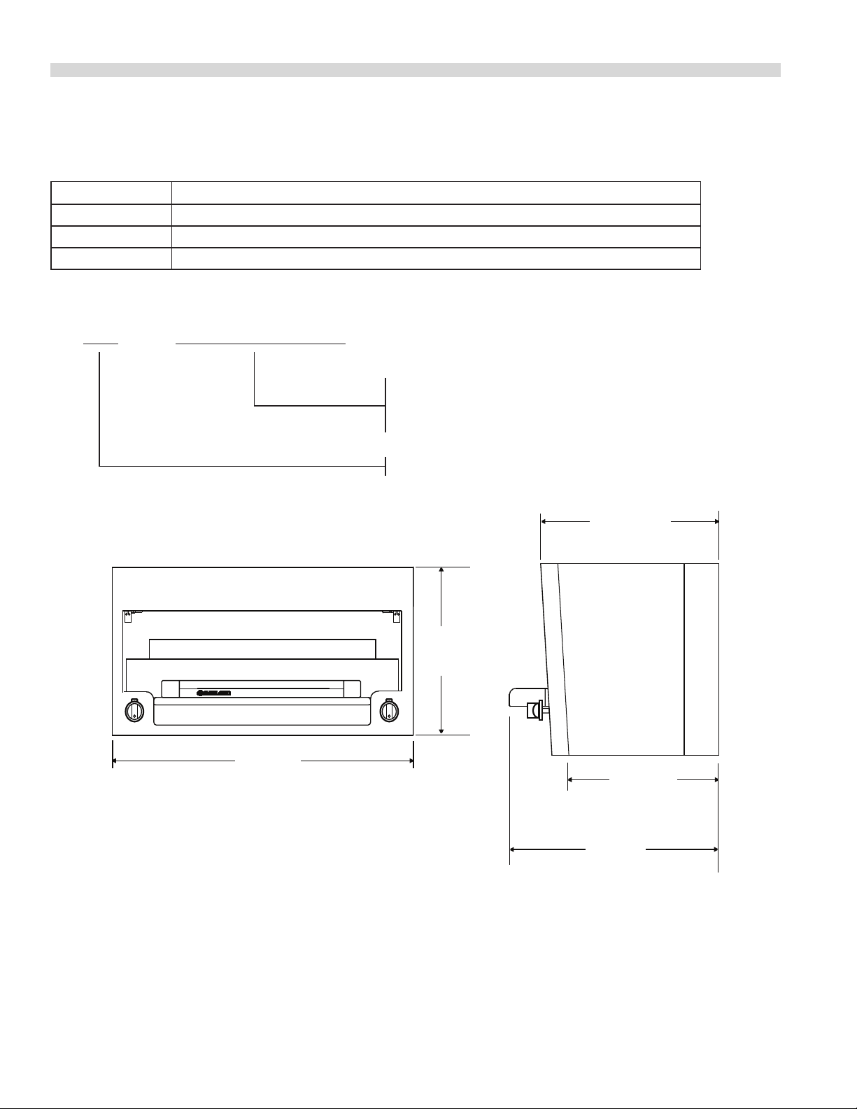
DIMENSIONS AND SPECIFICATIONS
MST SRC, SR16-280, SR16
SRC - Counter Top Version
SR16-280 - Restaurant Range Mount Version
SR16 - Heavy Duty Range Mount Version
Base Model Number
16 5/16"
[414mm]
34"
[864mm]
17 61/64"
[456mm]
16 13/16"
[427mm]
20 1/4"
[514mm]
Model Designation
MODEL DESCRIPTION
MSTSRC 864 mm wide x 414 mm high, infra-red counter mount salamander.
MSTSR16-280 864 mm wide x 1089 mm high, infra-red restaurant range mount salamander.
MSTSR16 864 mm wide x 1089 mm high, infra-red heavy duty range mount salamander.
Sux Denitions
Part # P143 (11/10/08)Page 4

DIMENSIONS AND SPECIFICATIONS Continued
Table A: Exterior Dimensions
MODEL
MSTSRC 414 16.513 864 34 514 20.25 70.3 155
MSTSR16 414 16.513 864 34 514 20.25 95.3 210
HEIGHT WIDTH DEPTH WEIGHT
mm ins mm ins mm ins kg lb
Table B: Gas Flow Rate Per Model
MODEL
MSTSRC 0.88 0.598
MSTSR16 0.88 0.598
NATURAL GAS (m3/h) PROPANE GAS (kg/h)
G20 @ 20mbar G31 @ 37/50 mbar
Table C: Nominal Heat Input (Gross) Per Model
(G20 @ 20 mbar) NATURAL GAS (G31 @ 37/50 mbar) PROPANE
MODEL
MSTSRC 9.23 31,500 33.23 8.35 28,500 30.1
MSTSR16 9.23 31,500 33.23 8.35 28,500 30.1
Nominal Heat Input (Gross) Nominal Heat Input (Gross)
kW BTU/HR MJ/HR kW BTU/HR MJ/HR
Table D: Setting Pressure / Injector Size
MODEL/
SECTION
ALL 20 8 1.6 1.6
NOTE: The pressure must be measured at the pressure test nipple located on the main manifold pipe with all burners lit.
Setting Pressure Injector Size Setting Pressure Injector Size
mbar “W.C. I.D # mm mbar “WC I.D. # mm
37 14.9 1.1 1.1
50 20 61 0.99
Table E: Setting Pressure For “MIN” Tap Position
2ND Family, Group H 3RD Family, Group 3P
(G20 @ 20 mbar) Natural Gas (G31 @ 37/50 mbar) Propane
MODELS
MSTSRC 10.5 4.2 23 9.4
MSTSR16 10.5 4.2 23 9.4
(G20 @ 20 mbar) NAT. GAS (G31 @ 37/50 mbar) PROPANE
mbar “ W.C. mbar “ W.C.
Part # P143 (11/10/08) Page 5
 Loading...