

Page 1
INSTALLATION,
OPERATING & SERVICE
MANUAL
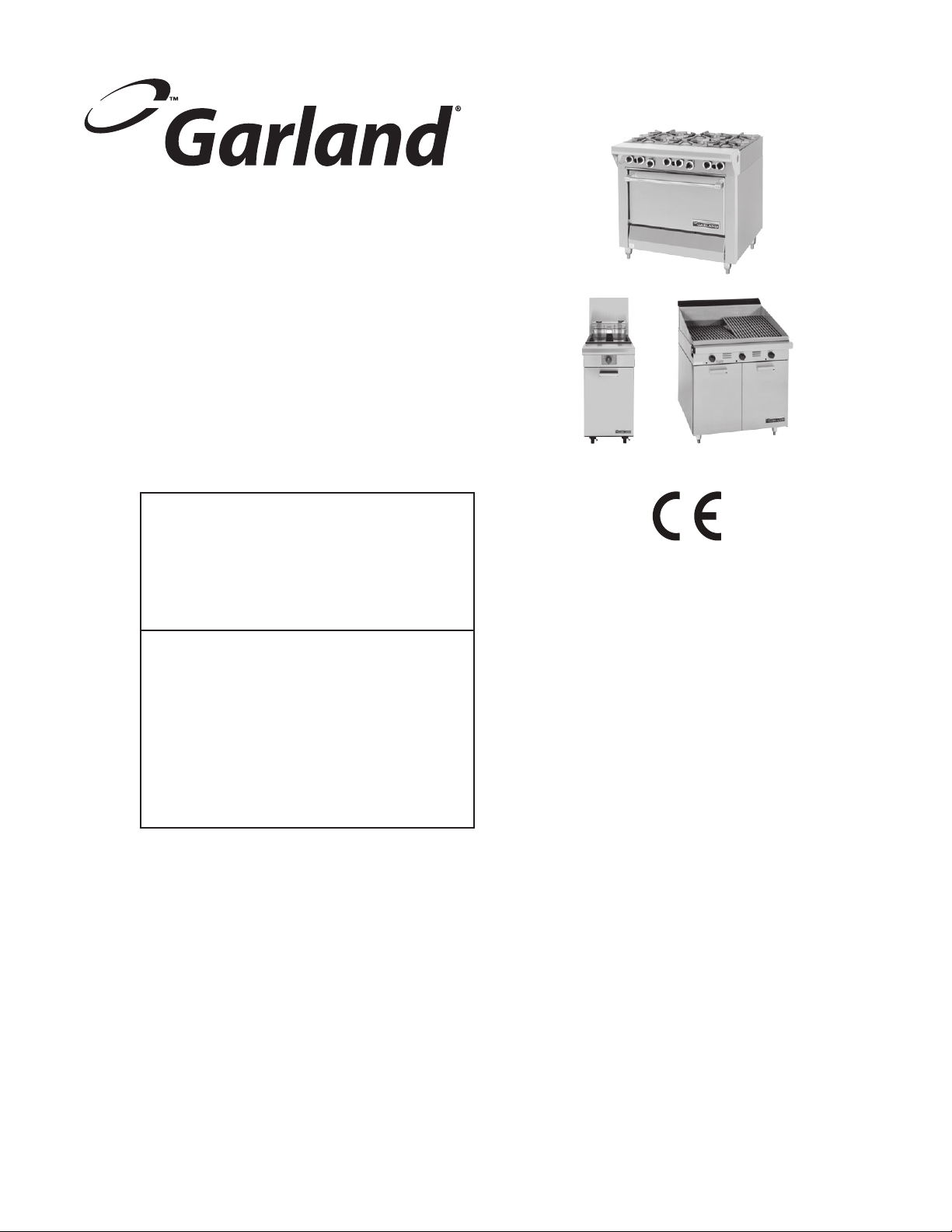
MASTER SERIES HEAVY DUTY
RANGES, FRYERS & BROILERS
FOR YOUR SAFETY:
DO NOT STORE OR USE GASOLINE
OR OTHER FLAMMABLE VAPORS OR
LIQUIDS IN THE VICINITY OF
THIS OR ANY OTHER
APPLIANCE
WARNING:
IMPROPER INSTALLATION, ADJUSTMENT,
ALTERATION, SERVICE OR MAINTENANCE
CAN CAUSE PROPERTY DAMAGE, INJURY,
OR DEATH. READ THE INSTALLATION,
OPERATING AND MAINTENANCE
INSTRUCTIONS THOROUGHLY
BEFORE INSTALLING OR
SERVICING THIS EQUIPMENT
PLEASE READ ALL SECTIONS OF THIS MANUAL
AND RETAIN FOR FUTURE REFERENCE.
THIS PRODUCT HAS BEEN CERTIFIED AS
COMMERCIAL COOKING EQUIPMENT AND
MUST BE INSTALLED BY PROFESSIONAL
PERSONNEL AS SPECIFIED.
For Your Safety:
Post in a prominent location, instructions to be
followed in the event the user smells gas. This
information shall be obtained by consulting
your local gas supplier.
Users are cautioned that maintenance and repairs must be performed by a Garland authorized service agent
using genuine Garland replacement parts. Garland will have no obligation with respect to any product that has been
improperly installed, adjusted, operated or not maintained in accordance with national and local codes or installation
instructions provided with the product, or any product that has its serial number defaced, obliterated or removed,
or which has been modified or repaired using unauthorized parts or by unauthorized service agents.
For a list of authorized service agents, please refer to the Garland web site at http://www.garland-group.com.
The information contained herein, (including design and parts specifications), may be superseded and is subject
to change without notice.
GARLAND COMMERCIAL INDUSTRIES
185 East South Street
Freeland, Pennsylvania 18224
Phone: (570) 636-1000
Fax: (570) 636-3903
Part # 4519069 (07/24/09) © 2004 Garland Commercial Industries, Inc.
Part # 4519069 (07/24/09) Page 1
GARLAND COMMERCIAL RANGES, LTD.
1177 Kamato Road, Mississauga, Ontario L4W 1X4
CANADA
Phone: 905-624-0260
Fax: 905-624-5669
Enodis UK LTD.
Swalloweld Way, Hayes, Middlesex UB3 1DQ ENGLAND
Telephone: 081-561-0433
Fax: 081-848-0041
Page 2

TABLE OF CONTENTS
TECHNICAL SPECIFICATIONS . . . . . . . . . . . . . . . . . . . . . . . . . . . . . . . . . . . . . . . . . . . . . . . . . . . . . . . . . . . 4
Table B: Model Designations . . . . . . . . . . . . . . . . . . . . . . . . . . . . . . . . . . . . . . . . . . . . . . . . . . . . . . . . . . . . . . . . . . . . . . 4
Table C: Exterior Dimensions . . . . . . . . . . . . . . . . . . . . . . . . . . . . . . . . . . . . . . . . . . . . . . . . . . . . . . . . . . . . . . . . . . . . . 6
Table D: Gas Flow Rate (Net) Per Model . . . . . . . . . . . . . . . . . . . . . . . . . . . . . . . . . . . . . . . . . . . . . . . . . . . . . . . . . . . 7
Table E: Heat Input (Gross) Per Burner / Burner Group. . . . . . . . . . . . . . . . . . . . . . . . . . . . . . . . . . . . . . . . . . . . . . 8
Table F: Pressure Setting / Injector Size . . . . . . . . . . . . . . . . . . . . . . . . . . . . . . . . . . . . . . . . . . . . . . . . . . . . . . . . . . . . 9
Table G: Pressure Setting For Low Tap Position . . . . . . . . . . . . . . . . . . . . . . . . . . . . . . . . . . . . . . . . . . . . . . . . . . . 10
Table H: Aeration Shutter Setting / Pilot Flame Length . . . . . . . . . . . . . . . . . . . . . . . . . . . . . . . . . . . . . . . . . . . .10
Table I: Australia Only Nominal Gas Consumption & Injector Sizes . . . . . . . . . . . . . . . . . . . . . . . . . . . . . . . . . 11
Table J: Clearances . . . . . . . . . . . . . . . . . . . . . . . . . . . . . . . . . . . . . . . . . . . . . . . . . . . . . . . . . . . . . . . . . . . . . . . . . . . . . . 11
STATUTORY REGULATIONS . . . . . . . . . . . . . . . . . . . . . . . . . . . . . . . . . . . . . . . . . . . . . . . . . . . . . . . . . . . . 12
INTRODUCTION . . . . . . . . . . . . . . . . . . . . . . . . . . . . . . . . . . . . . . . . . . . . . . . . . . . . . . . . . . . . . . . . . . . . . . 12
Uncrating . . . . . . . . . . . . . . . . . . . . . . . . . . . . . . . . . . . . . . . . . . . . . . . . . . . . . . . . . . . . . . . . . . . . . . . . . . . . . . . . . . . . . . . 12
Rating Plate Location . . . . . . . . . . . . . . . . . . . . . . . . . . . . . . . . . . . . . . . . . . . . . . . . . . . . . . . . . . . . . . . . . . . . . . . . . . . .12
Safety . . . . . . . . . . . . . . . . . . . . . . . . . . . . . . . . . . . . . . . . . . . . . . . . . . . . . . . . . . . . . . . . . . . . . . . . . . . . . . . . . . . . . . . . . .13
Optional Extras . . . . . . . . . . . . . . . . . . . . . . . . . . . . . . . . . . . . . . . . . . . . . . . . . . . . . . . . . . . . . . . . . . . . . . . . . . . . . . . . .13
INSTALLATION . . . . . . . . . . . . . . . . . . . . . . . . . . . . . . . . . . . . . . . . . . . . . . . . . . . . . . . . . . . . . . . . . . . . . . . . 13
Gas Supply . . . . . . . . . . . . . . . . . . . . . . . . . . . . . . . . . . . . . . . . . . . . . . . . . . . . . . . . . . . . . . . . . . . . . . . . . . . . . . . . . . . . . .13
Electrical Supply . . . . . . . . . . . . . . . . . . . . . . . . . . . . . . . . . . . . . . . . . . . . . . . . . . . . . . . . . . . . . . . . . . . . . . . . . . . . . . . .13
COMMISSIONING . . . . . . . . . . . . . . . . . . . . . . . . . . . . . . . . . . . . . . . . . . . . . . . . . . . . . . . . . . . . . . . . . . . . . 14
Testing & Adjustments . . . . . . . . . . . . . . . . . . . . . . . . . . . . . . . . . . . . . . . . . . . . . . . . . . . . . . . . . . . . . . . . . . . . . . . . . .14
Pressure Settings (All Models Except Fryers) . . . . . . . . . . . . . . . . . . . . . . . . . . . . . . . . . . . . . . . . . . . . . . . . . . . . . .14
Pressure Settings - Fryers . . . . . . . . . . . . . . . . . . . . . . . . . . . . . . . . . . . . . . . . . . . . . . . . . . . . . . . . . . . . . . . . . . . . . . . . 14
Burner Adjustments . . . . . . . . . . . . . . . . . . . . . . . . . . . . . . . . . . . . . . . . . . . . . . . . . . . . . . . . . . . . . . . . . . . . . . . . . . . . . 14
Thermostat Bypass Adjustment - Oven . . . . . . . . . . . . . . . . . . . . . . . . . . . . . . . . . . . . . . . . . . . . . . . . . . . . . . . . . .14
Oven Thermostat Calibration . . . . . . . . . . . . . . . . . . . . . . . . . . . . . . . . . . . . . . . . . . . . . . . . . . . . . . . . . . . . . . . . . . . . 15
Open Type Hot Plate . . . . . . . . . . . . . . . . . . . . . . . . . . . . . . . . . . . . . . . . . . . . . . . . . . . . . . . . . . . . . . . . . . . . . . . . . . . . 15
Solid Top/Griddle . . . . . . . . . . . . . . . . . . . . . . . . . . . . . . . . . . . . . . . . . . . . . . . . . . . . . . . . . . . . . . . . . . . . . . . . . . . . . . . 15
Front Fired Solid Top . . . . . . . . . . . . . . . . . . . . . . . . . . . . . . . . . . . . . . . . . . . . . . . . . . . . . . . . . . . . . . . . . . . . . . . . . . . .15
Broiler Burner . . . . . . . . . . . . . . . . . . . . . . . . . . . . . . . . . . . . . . . . . . . . . . . . . . . . . . . . . . . . . . . . . . . . . . . . . . . . . . . . . . .16
Open Burners . . . . . . . . . . . . . . . . . . . . . . . . . . . . . . . . . . . . . . . . . . . . . . . . . . . . . . . . . . . . . . . . . . . . . . . . . . . . . . . . . . .16
Oven . . . . . . . . . . . . . . . . . . . . . . . . . . . . . . . . . . . . . . . . . . . . . . . . . . . . . . . . . . . . . . . . . . . . . . . . . . . . . . . . . . . . . . . . . . .16
Solid Hot Plate/Griddle . . . . . . . . . . . . . . . . . . . . . . . . . . . . . . . . . . . . . . . . . . . . . . . . . . . . . . . . . . . . . . . . . . . . . . . . . . 17
Front Fired Hot Top . . . . . . . . . . . . . . . . . . . . . . . . . . . . . . . . . . . . . . . . . . . . . . . . . . . . . . . . . . . . . . . . . . . . . . . . . . . . .17
Broiler . . . . . . . . . . . . . . . . . . . . . . . . . . . . . . . . . . . . . . . . . . . . . . . . . . . . . . . . . . . . . . . . . . . . . . . . . . . . . . . . . . . . . . . . . . 17
Fryer . . . . . . . . . . . . . . . . . . . . . . . . . . . . . . . . . . . . . . . . . . . . . . . . . . . . . . . . . . . . . . . . . . . . . . . . . . . . . . . . . . . . . . . . . . . .17
OPERATION . . . . . . . . . . . . . . . . . . . . . . . . . . . . . . . . . . . . . . . . . . . . . . . . . . . . . . . . . . . . . . . . . . . . . . . . . . 17
Open Top Burners (MST Models) . . . . . . . . . . . . . . . . . . . . . . . . . . . . . . . . . . . . . . . . . . . . . . . . . . . . . . . . . . . . . . . . . 17
Hot Top And Spectro-top Sections (MST Models) . . . . . . . . . . . . . . . . . . . . . . . . . . . . . . . . . . . . . . . . . . . . . . . . . 17
Standard Ovens . . . . . . . . . . . . . . . . . . . . . . . . . . . . . . . . . . . . . . . . . . . . . . . . . . . . . . . . . . . . . . . . . . . . . . . . . . . . . . . . . 18
RC Convection Ovens . . . . . . . . . . . . . . . . . . . . . . . . . . . . . . . . . . . . . . . . . . . . . . . . . . . . . . . . . . . . . . . . . . . . . . . . . . .18
Char-Broiler (MST Models) . . . . . . . . . . . . . . . . . . . . . . . . . . . . . . . . . . . . . . . . . . . . . . . . . . . . . . . . . . . . . . . . . . . . . . . 18
MAINTENANCE AND CLEANING. . . . . . . . . . . . . . . . . . . . . . . . . . . . . . . . . . . . . . . . . . . . . . . . . . . . . . . . 19
Seasoning . . . . . . . . . . . . . . . . . . . . . . . . . . . . . . . . . . . . . . . . . . . . . . . . . . . . . . . . . . . . . . . . . . . . . . . . . . . . . . . . . . . . . .19
Griddles . . . . . . . . . . . . . . . . . . . . . . . . . . . . . . . . . . . . . . . . . . . . . . . . . . . . . . . . . . . . . . . . . . . . . . . . . . . . . . . . . . . . 19
Cast Iron Top Grates And Ring Grates . . . . . . . . . . . . . . . . . . . . . . . . . . . . . . . . . . . . . . . . . . . . . . . . . . . . . . . . 20
Part # 4519069 (07/24/09)Page 2
Page 3

TABLE OF CONTENTS continued
Cleaning . . . . . . . . . . . . . . . . . . . . . . . . . . . . . . . . . . . . . . . . . . . . . . . . . . . . . . . . . . . . . . . . . . . . . . . . . . . . . . . . . . . . . . . . 20
Raw Steel Finishes:. . . . . . . . . . . . . . . . . . . . . . . . . . . . . . . . . . . . . . . . . . . . . . . . . . . . . . . . . . . . . . . . . . . . . . . . . . 20
Painted Finishes:. . . . . . . . . . . . . . . . . . . . . . . . . . . . . . . . . . . . . . . . . . . . . . . . . . . . . . . . . . . . . . . . . . . . . . . . . . . . 20
Stainless Steel Finishes: . . . . . . . . . . . . . . . . . . . . . . . . . . . . . . . . . . . . . . . . . . . . . . . . . . . . . . . . . . . . . . . . . . . . . 20
Oven Interiors (Porcelain Enamel): . . . . . . . . . . . . . . . . . . . . . . . . . . . . . . . . . . . . . . . . . . . . . . . . . . . . . . . . . . . 20
Griddles . . . . . . . . . . . . . . . . . . . . . . . . . . . . . . . . . . . . . . . . . . . . . . . . . . . . . . . . . . . . . . . . . . . . . . . . . . . . . . . . . . . . 20
Open Top Burners . . . . . . . . . . . . . . . . . . . . . . . . . . . . . . . . . . . . . . . . . . . . . . . . . . . . . . . . . . . . . . . . . . . . . . . . . . 21
Cast Iron Top Grates And Ring Grates . . . . . . . . . . . . . . . . . . . . . . . . . . . . . . . . . . . . . . . . . . . . . . . . . . . . . . . . 21
Cast Iron Even Heat Hot Tops And Spectro-Heat Tops . . . . . . . . . . . . . . . . . . . . . . . . . . . . . . . . . . . . . . . . 21
Adjustments . . . . . . . . . . . . . . . . . . . . . . . . . . . . . . . . . . . . . . . . . . . . . . . . . . . . . . . . . . . . . . . . . . . . . . . . . . . . . . . . . . . .21
Top and Oven Orices. . . . . . . . . . . . . . . . . . . . . . . . . . . . . . . . . . . . . . . . . . . . . . . . . . . . . . . . . . . . . . . . . . . . . . . 21
Pilot Adjustment. . . . . . . . . . . . . . . . . . . . . . . . . . . . . . . . . . . . . . . . . . . . . . . . . . . . . . . . . . . . . . . . . . . . . . . . . . . . 21
Burner Gas/Air Adjustments . . . . . . . . . . . . . . . . . . . . . . . . . . . . . . . . . . . . . . . . . . . . . . . . . . . . . . . . . . . . . . . . . 21
CONVECTION OVEN (RC) – OPERATING TIPS . . . . . . . . . . . . . . . . . . . . . . . . . . . . . . . . . . . . . . . . . . . . 22
SERVICING . . . . . . . . . . . . . . . . . . . . . . . . . . . . . . . . . . . . . . . . . . . . . . . . . . . . . . . . . . . . . . . . . . . . . . . . . . .23
Cleaning/Servicing Burners . . . . . . . . . . . . . . . . . . . . . . . . . . . . . . . . . . . . . . . . . . . . . . . . . . . . . . . . . . . . . . . . . . . . . .23
Open-type Burners . . . . . . . . . . . . . . . . . . . . . . . . . . . . . . . . . . . . . . . . . . . . . . . . . . . . . . . . . . . . . . . . . . . . . . . . . 23
Front Fired Solid Top Burners. . . . . . . . . . . . . . . . . . . . . . . . . . . . . . . . . . . . . . . . . . . . . . . . . . . . . . . . . . . . . . . . 23
Solid Hot Plate/Griddle Burners: . . . . . . . . . . . . . . . . . . . . . . . . . . . . . . . . . . . . . . . . . . . . . . . . . . . . . . . . . . . . . 23
Oven Burners – Models With Sux R . . . . . . . . . . . . . . . . . . . . . . . . . . . . . . . . . . . . . . . . . . . . . . . . . . . . . . . . 23
Oven Burners – Models With Sux RC . . . . . . . . . . . . . . . . . . . . . . . . . . . . . . . . . . . . . . . . . . . . . . . . . . . . . . . 23
Broiler . . . . . . . . . . . . . . . . . . . . . . . . . . . . . . . . . . . . . . . . . . . . . . . . . . . . . . . . . . . . . . . . . . . . . . . . . . . . . . . . . . . . . . 24
Pilot Burner Cleaning . . . . . . . . . . . . . . . . . . . . . . . . . . . . . . . . . . . . . . . . . . . . . . . . . . . . . . . . . . . . . . . . . . . . . . . . . . . .24
Hot Plate/Solid Top/Griddle/Broiler . . . . . . . . . . . . . . . . . . . . . . . . . . . . . . . . . . . . . . . . . . . . . . . . . . . . . . . . . . 24
Oven . . . . . . . . . . . . . . . . . . . . . . . . . . . . . . . . . . . . . . . . . . . . . . . . . . . . . . . . . . . . . . . . . . . . . . . . . . . . . . . . . . . . . . . 24
Fryer . . . . . . . . . . . . . . . . . . . . . . . . . . . . . . . . . . . . . . . . . . . . . . . . . . . . . . . . . . . . . . . . . . . . . . . . . . . . . . . . . . . . . . . 24
Thermostat Calibration . . . . . . . . . . . . . . . . . . . . . . . . . . . . . . . . . . . . . . . . . . . . . . . . . . . . . . . . . . . . . . . . . . . . . . . . . .24
Oven . . . . . . . . . . . . . . . . . . . . . . . . . . . . . . . . . . . . . . . . . . . . . . . . . . . . . . . . . . . . . . . . . . . . . . . . . . . . . . . . . . . . . . . 24
Fryer . . . . . . . . . . . . . . . . . . . . . . . . . . . . . . . . . . . . . . . . . . . . . . . . . . . . . . . . . . . . . . . . . . . . . . . . . . . . . . . . . . . . . . . 25
REPLACEMENT OF PARTS . . . . . . . . . . . . . . . . . . . . . . . . . . . . . . . . . . . . . . . . . . . . . . . . . . . . . . . . . . . . .26
Gas Taps . . . . . . . . . . . . . . . . . . . . . . . . . . . . . . . . . . . . . . . . . . . . . . . . . . . . . . . . . . . . . . . . . . . . . . . . . . . . . . . . . . . . . . . .26
Oven Thermostat . . . . . . . . . . . . . . . . . . . . . . . . . . . . . . . . . . . . . . . . . . . . . . . . . . . . . . . . . . . . . . . . . . . . . . . . . . . . . . .26
Pilot/Thermocouple/Spark Electrode . . . . . . . . . . . . . . . . . . . . . . . . . . . . . . . . . . . . . . . . . . . . . . . . . . . . . . . . . . . .26
Hot Plate (MST Only) . . . . . . . . . . . . . . . . . . . . . . . . . . . . . . . . . . . . . . . . . . . . . . . . . . . . . . . . . . . . . . . . . . . . . . . . 26
Griddle/Solid Top/Front-Fired Hot Top/Broiler. . . . . . . . . . . . . . . . . . . . . . . . . . . . . . . . . . . . . . . . . . . . . . . . 26
Oven . . . . . . . . . . . . . . . . . . . . . . . . . . . . . . . . . . . . . . . . . . . . . . . . . . . . . . . . . . . . . . . . . . . . . . . . . . . . . . . . . . . . . . . 27
Spark Ignition Module Models With Sux E. . . . . . . . . . . . . . . . . . . . . . . . . . . . . . . . . . . . . . . . . . . . . . . . . . 27
Push Button Spark Switch Models With Sux E . . . . . . . . . . . . . . . . . . . . . . . . . . . . . . . . . . . . . . . . . . . . . . 27
RC Oven . . . . . . . . . . . . . . . . . . . . . . . . . . . . . . . . . . . . . . . . . . . . . . . . . . . . . . . . . . . . . . . . . . . . . . . . . . . . . . . . . . . . . . . . 27
Power Switch . . . . . . . . . . . . . . . . . . . . . . . . . . . . . . . . . . . . . . . . . . . . . . . . . . . . . . . . . . . . . . . . . . . . . . . . . . . . . . . 27
CONVERSION INSTRUCTIONS. . . . . . . . . . . . . . . . . . . . . . . . . . . . . . . . . . . . . . . . . . . . . . . . . . . . . . . . . .28
TROUBLE SHOOTING GUIDE . . . . . . . . . . . . . . . . . . . . . . . . . . . . . . . . . . . . . . . . . . . . . . . . . . . . . . . . . . .29
Open Type Hot Plate, Solid Hot Top, Griddles And Broilers . . . . . . . . . . . . . . . . . . . . . . . . . . . . . . . . . . . . . . . .29
Standard And Convection Ovens . . . . . . . . . . . . . . . . . . . . . . . . . . . . . . . . . . . . . . . . . . . . . . . . . . . . . . . . . . . . . . . . 29
Standard Oven Only . . . . . . . . . . . . . . . . . . . . . . . . . . . . . . . . . . . . . . . . . . . . . . . . . . . . . . . . . . . . . . . . . . . . . . . . . . . . .30
Convection Base Oven Only . . . . . . . . . . . . . . . . . . . . . . . . . . . . . . . . . . . . . . . . . . . . . . . . . . . . . . . . . . . . . . . . . . . . .30
Fryers . . . . . . . . . . . . . . . . . . . . . . . . . . . . . . . . . . . . . . . . . . . . . . . . . . . . . . . . . . . . . . . . . . . . . . . . . . . . . . . . . . . . . . . . . . .31
Part # 4519069 (07/24/09) Page 3
Page 4

TECHNICAL SPECIFICATIONS
Table B: Model Designations
MODEL MM Ins DESCRIPTION
MST42R(E) 864 34
MST42RC(E) 864 34
MST42S(E) 864 34
MST42T(E) 864 34
MST43R(E) 864 34 Range with oven and six open top burners
MST43RC(E) 864 34 Range with convection oven and six open top burners
MST43S(E) 864 34 Range with storage base and six open top burners
MST43T(E) 864 34 Modular top with six open top burners
MST44R(E) 864 34 Range with oven and four open top burners
MST44RC(E) 864 34 Range with convection oven and four open top burners
MST44S(E) 864 34 Range with storage base and four open top burners
MST44T(E) 864 34 Modular top with four open top burners
MST45R(E) 864 34 Range with oven and two 330 mm wide front red solid hot plate sections
MST45RC(E) 864 34 Range with convection oven and two 330 mm wide front red solid hot plate sections
MST45S(E) 864 34 Range with storage base and two 330 mm wide front red solid hot plate sections
MST45T(E) 864 34 Modular top with two 330 mm wide front red solid hot plate sections
MST46R(E) 864 34 Range with oven and two 330 mm wide even heat solid top sections
MST46RC(E) 864 34 Range with convection over and two 330 mm wide even heat solid top sections
MST46S(E) 864 34 Range with storage base and two 330 mm wide even heat solid top sections
MST46T(E) 864 34 Modular top with two 330 mm wide even heat solid top sections
MST47R(E) 864 34 Range with oven and 864 mm wide tap controlled griddle
MST47RC(E) 864 34 Range with convection oven and 864 mm wide tap controlled griddle
MST47S(E) 864 34 Range with storage base and 864 mm wide tap controlled griddle
MST47T(E) 864 34 Modular top and 864 mm wide tap controlled griddle
MST54R(E) 864 34 Range with oven, two open top burners & a 330 mm wide front red solid top section
MST54RC(E) 864 34
MST54S(E) 864 34
MST54T(E) 864 34
Range with oven, two open top burners & a 432 mm wide solid hot plate or
optional griddle
Range with convection oven, two open top burners & a 432 mm wide solid hot plate or
option griddle
Range with storage compartment, two open top burners & a 432 mm wide
solid hot plate optional griddle
Modular top with two open top burners & a 432 mm wide solid hot plate or
optional griddle.
Range with convection oven, two open top burners & a 330 mm wide
front red solid top section
Range with a storage base, two open top burners & a 330 mm wide front
red solid top section
Modular top with two open top burners & a 330 mm wide
front red solid top section
Part # 4519069 (07/24/09)Page 4
Page 5
TECHNICAL SPECIFICATIONS continued
MODEL MM Ins DESCRIPTION
MST4S(E) 432 17 Range with storage base and two open top burners
MST4T(E) 432 17 Modular top with two open top burners
MST6S(E) 432 17 Range with 330 mm wide solid hot plate
MST6T(E) 432 17 Modular top with 330 mm wide solid hot plate
MST7S(E) 432 17 Range with 330 mm wide tap controlled griddle
MST7T(E) 432 17 Modular top with 330 mm wide tap controlled griddle
MST17B(E) 432 17 Char broiler
MST24BT(E) 610 24 Char broiler
MST34BT(E) 864 34 Char broiler
MST35 432 17 Deep fat fryer
MST70 610 24 Deep fat fryer
PREFIX DEFINITIONS: SUFFIX DEFINITIONS:
MST Master Sentry c/w total ame failure E Electric spark pilot ignition
B Broiler
T Modular top section
S Storage cabinet under top section
RC Range with convection oven
R Range with standard oven
Part # 4519069 (07/24/09) Page 5
Page 6

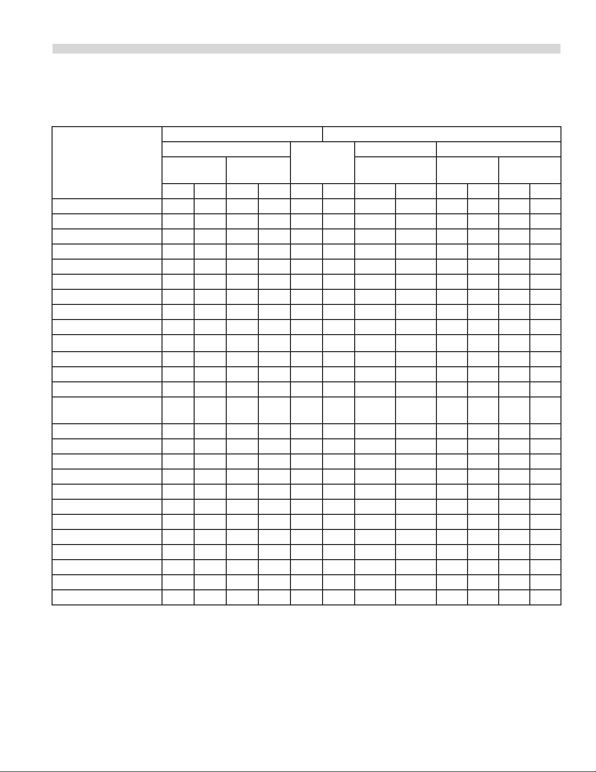
TECHNICAL SPECIFICATIONS continued
Table C: Exterior Dimensions
MODELS
MST42R(E) & RC(E) 952.5 37.5 863.6 34 965.2 38 235.9 520
MST42S(E) 952.5 37.5 863.6 34 965.2 38 222.3 490
MST42T(E) 317.5 12.5 863.6 34 965.2 38 99.8 220
MST43R(E) & RC(E) 882.6 34.75 863.6 34 965.2 38 213.2 470
MST43S(E) 882.6 34.75 863.6 34 965.2 38 158.8 350
MST43T(E) 247.6 9.75 863.6 34 965.2 38 99.8 220
MST44R(E) & RC(E) 882.6 34.75 863.6 34 965.2 38 231.4 510
MST44S(E) 882.6 34.75 863.6 34 965.2 38 176.9 390
MST44T(E) 247.6 9.75 863.6 34 965.2 38 108.9 240
MST45R(E) & RC(E) 869.9 34.25 863.6 34 965.2 38 254.1 560
MST45S(E) 369.9 34.25 863.6 34 965.2 38 199.6 440
MST45T(E) 234.9 9.25 863.6 34 965.2 38 136.1 300
MST46R(E) & RC(E) 869.9 34.25 863.6 34 965.2 38 240.5 530
MST46S(E) 869.9 34.25 863.6 34 965.2 38 186 410
MST46T(E) 234.9 9.25 863.6 34 965.2 38 115.7 255
MST47R(E) & RC(E) 952.5 37.5 863.6 34 965.2 38 242.7 535
MST47S(E) 952.5 37.5 863.6 34 965.2 38 188.2 415
MST47T(E) 317.5 12.5 863.6 34 965.2 38 117.9 260
MST54R(E) & RC(E) 882.6 34.75 863.6 34 965.2 38 235.9 520
MST54S(E) 882.6 34.75 863.6 34 965.2 38 181.5 400
MST54T(E) 247.6 9.75 863.6 34 965.2 38 122.5 270
MST4S(E) 882.6 34.75 431.8 17 965.2 38 95.3 210
MST4T(E) 317.5 12.5 431.8 17 965.2 38 59 130
MST6S(E) 882.6 34.75 431.8 17 965.2 38 99.8 220
MST6T(E) 234.9 9.25 431.8 17 965.2 38 54.5 120
MST7S(E) 952.5 37.5 431.8 17 965.2 38 113.5 250
MST7T(E) 317.5 12.5 431.8 17 965.2 38 61.3 135
MST17B 1092.2 43 431.8 17 965.2 38 100 220
MST24B 1092.2 43 609.6 24 965.2 38 149.7 330
MST34B 1092.2 43 863.6 34 965.2 38 231.4 510
MST35F 793.7 31.25 431.8 17 965.2 38 86.2 190
MST70F 793.7 31.25 609.6 24 965.2 38 120.2 265
HEIGHT WIDTH DEPTH WEIGHT
mm ins. mm ins. mm ins. kg lb
NOTE: Height dimensions are specied with 4 inch (101.6mm) legs. Add 2 inches (50.8mm) for 6 inch legs.
Part # 4519069 (07/24/09)Page 6
Page 7
TECHNICAL SPECIFICATIONS continued
Table D: Gas Flow Rate (Net) Per Model
MODEL
MST42R(E) & RC(E) 2.99 3.47 2.24
MST42S(E) & T(E) 1.87 2.18 1.4
MST43R(E) & RC(E) 5.14 5.97 3.35
MST43S(E) & T(E) 4.02 4.68 2.51
MST44R(E) & RC(E) 4.47 5.19 3.35
MST44S(E) & T(E) 3.35 3.9 2.51
MST45R(E) & RC(E) 3.35 3.9 2.51
MST45S(E) & T(E) 2.24 2.6 1.68
MST46R(E) & RC(E) 3.38 3.93 2.54
MST46S(E) & T(E) 2.26 2.63 1.70
MST47R(E) & RC(E) 3.63 4.22 2.72
MST47S(E) & T(E) 2.51 2.92 1.89
MST54R(E) & RC(E) 3.21 3.73 2.41
MST54S(E) & T(E) 2.09 2.43 1.57
MST4S(E) & T(E) 1.12 1.30 0.84
MST6S(E) & T(E) 0.76 0.88 0.57
MST7S(E) & T(E) 0.76 0.88 0.57
MST17B(E) 1.26 1.46 0.94
MST24B(E) 1.67 1.95 1.26
MST34B(E) 2.51 2.92 1.89
MST35F 3.07 3.57 2.31
MST70F 3.49 4.06 2.62
2nd Family (m3/h) NET 3rd Family (kg/h)
G20 @ 20mbar G25 @ 25mbar G31 @ 37/50mbar
Part # 4519069 (07/24/09) Page 7
Page 8
TECHNICAL SPECIFICATIONS continued
Table E: Heat Input (Gross) Per Burner / Burner Group
2nd Family, Groups H,L & E 3rd Family, Group 3P
MODELS / SECTION
MST40(E) Oven 11.72 42.2 11.72 42.20
MST40RC(E) Oven 11.72 42.2 10.3 36.90
MST42(E) Open Top 5.86 21.1 5.86 21.10
MST42(E) Solid Top/Griddle 7.91 28.48 7.91 28.48
MST43(E) Open Top 7.03 25.32 5.86 21.10
MST44(E) Open Top 8.79 31.65 8.79 31.65
MST45(E) Solid Top 11.72 42.2 11.72 42.20
MST46(E) Solid Top 7.91 28.48 7.91 28.48
MST47(E) Griddle 8.79 31.65 8.79 31.65
MST54(E) Solid Top 10.25 36.92 10.25 36.92
MST54(E) Open Top 5.86 21.1 5.86 21.10
MST4(E) Open Top 5.86 21.1 5.86 21.10
MST6(E) Solid Top 7.91 28.48 7.91 28.48
MST7(E) Griddle 7.91 28.48 7.91 28.48
MST17B(E) Broiler 8.79/4.39 31.65/ 15.82 8.79/4.39 31.65/ 15.82
MST24B(E) Broiler 8.79 31.65 8.79 31.65
MST34B(E) Broiler 8.79 31.65 8.79 31.65
MST35F Fryer 32.23 116.04 32.23 116.04
MST70F Fryer 36.63 131.86 36.63 131.86
(G20/G25 @ 20/25 mbar) Nat Gas (G31 @ 37/50 mbar) Propane
Per burner / section Per burner / section
kW MJ/HR kW MJ/HR
Part # 4519069 (07/24/09)Page 8
Page 9
TECHNICAL SPECIFICATIONS continued
Table F: Pressure Setting / Injector Size
2nd Family, Groups H, L & E 3rd Family, Group 3P
Setting Pressure
MODEL/SECTION
MST42(R,RC,S & T)(E) 20 8.0 25 10 – – 37/50 14.8/20 – – – –
MST43(R,RC,S & T)(E) 20 8.0 25 10 – – 37/50 14.8/20 – – – –
MST44(R,RC,S & T)(E) 20 8.0 25 10 – – 37/50 14.8/20 – – – –
MST45(R,RC,S & T)(E) 20 8.0 25 10 – – 37/50 14.8/20 – – – –
MST46(R,RC,S & T)(E) 20 8.0 25 10 – – 37/50 14.8/20 – – – –
MST47(R,RC,S & T)(E) 20 8.0 25 10 – – 37/50 14.8/20 – – – –
MST54(R,RC,S & T)(E) 20 8.0 25 10 – – 37/50 14.8/20 – – – –
MST4(S & T)(E) 20 8.0 25 10 – – 37/50 14.8/20 – – – –
MST6(S & T)(E) 20 8.0 25 10 – – 37/50 14.8/20 – – – –
MST7(S & T)(E) 20 8.0 25 10 – – 37/50 14.8/20 – – – –
G20 @ 20
mbar
mbar “WC mbar “WC DMS mm mbar “WC DMS mm DMS mm
G25 & 25
mbar
Injector Size
Setting Pressure Injector Size
G31 @ 37/50
mbar
37 mbar 50 mbar
MST40(E) Oven – – – – 31 2.65 – – 50 1.78 53 1.5
MST40RC(E) Oven – – – – 31 2.65 – – 50 1.6 53 1.5
MST42(E) Open Top – – – – – – – – – – – –
MST42(E)
Solid Top/Griddle
MST43(E) Open Top – – – – 1.9 1.9 – – 1.3 1.3 1.2 1.2
MST44(E) Open Top – – – – – – – – – – – –
MST45(E) Solid Top – – – – 1.4 1.4 – – 63 0.95 66 0.85
MST46(E) Solid Top – – – – 45 2.08 – – 1.4 1.4 1.25 1.2
MST47(E) Griddle – – – – 44 2.18 – – 53 1.51 1.35 1.3
MST54(E) Solid Top – – – – – – – – – – – –
MST54(E) Open Top – – – – – – – – – – – –
MST17B(E) Broiler 20 8.0 25 10 1.5 1.5 37/50 14.8/20 60 1.02 63 0.95
MST24B(E) Broiler 20 8.0 25 10 1.5 1.5 37/50 14.8/20 60 1.02 63 0.95
MST34B(E) Broiler 20 8.0 25 10 1.5 1.5 37/50 14.8/20 60 1.02 63 0.95
MST35F Fryer 10.5 4.2 N/A N/A 1.7 1.7 22.4 9.0 1.0 1.0 1.0 1.0
MST70F Fryer 10.5 4.2 N/A N/A 1.2 1.2 22.4 9.0 0.82 0.82 0.82 0.82
– – – – 45 2.08 – – 1.4 1.4 1.2 1.2
Part # 4519069 (07/24/09) Page 9
Page 10
TECHNICAL SPECIFICATIONS continued
Table G: Pressure Setting For Low Tap Position
2nd Family, Groups H, L & E 3rd Family, Group 3P
MODELS/SECTION
MST40(E) Oven 1.2 1.2
MST42(E) Hot ToP 2.0 3.0
MST42(E) Griddle 2.0 3.0
MST45(E) Hot Top 3.7 11.0
MST46(E) Hot Top 2.0 3.0
MST47(E) Griddle 2.0 3.0
MST54(E) Hot Top – –
MST6(E) Hot Top 2.0 3.0
MST7(E) Griddle 2.0 3.0
MST(17,24,34)(E) Broiler 2.0 7.0
G20/G25 @ 20/25 mbar
Natural Gas
mbar mbar
G31 @ 37/50 mbar
Propane
Table H: Aeration Shutter Setting / Pilot Flame Length
2nd Family, Groups H, L & E 3rd Family, Group 3P
SECTION
Oven 41.3 1.625 42.9 1.688 12.7 0.5
Open Burner 22.0 0.875 25.4 1.0 12.7 0.5
Griddle 25.4 1.0 26.9 1.062 12.7 0.5
Hot Top 25.4 1.0 19 0.75 12.7 0.5
Front Fired Hot Top 26.9 1.062 25.4 1.0 12.7 0.5
Broiler 25.4 1.0 25.4 1.0 12.7 0.5
Fryer N/A N/A N/A N/A 12.7 0.5
G20/G25 @ 20/25 mbar
Natural Gas
mm Ins. mm Ins. mm Ins.
G31 @ 37/50 mbar
Propane
Pilot Flame Length
Part # 4519069 (07/24/09)Page 10
Page 11

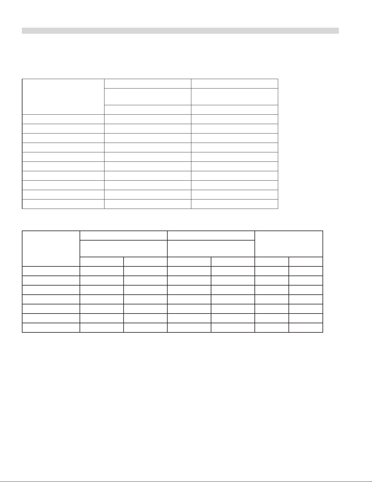
TECHNICAL SPECIFICATIONS continued
Table I: Australia Only Nominal Gas Consumption & Injector Sizes
NATURAL GAS PROPANE GAS
MODEL/SECTION
Standard Oven 3.25 42.20 1.0 1.70 36.90 2.49
Convection Oven 3.20 36.90 1 1.70 36.90 2.49
MST43 Open Top 2.35 25.30 1 1.40 21.10 2.49
MST4, 44 Open Top 2.64 36.90 1 1.78 36.90 2.49
MST5, 45 Front Fired Hot Top 1.70 12.30 1 1.07 12.30 2.49
MST6, 46 Even Heat Hot Top 2.85 28.50 1 1.51 28.50 2.49
MST7, 47 Griddle 3.05 31.65 1 1.70 31.65 2.49
MST17,24,30,34B 1.90 33 1 1.15 33 2.49
Table J: Clearances
CLEARANCE FROM COMBUSTIBLE CONSTRUCTION
Model
MST43(R,RC,S,E) 280 11 152 6 Combustible
MST43T 280 11 152 6 Non-Combustible
MST45,5(R,RC,S,E) 150 6 152 6 Combustible
MST45,5(T,E) 150 6 152 6 Non-Combustible
MST42,44,46,47,54,4,6,7(R,RC,S,E) 356 14 152 6 Combustible
MST42,44,46,47,54,4,6,7(T,E) 356 14 152 6 Non-Combustible
MST17,24,34B – – – – Combustible
MST35,70F 152 6 152 6 Combustible
INJ.DIA
mm.
mm Ins. mm Ins.
MJ/H
Sides Rear Base
Gas Pressure
(kPa)
INJ.DIA
mm
MJ/H
Gas Pressure
(kPa)
CLEARANCE FROM NON-COMBUSTIBLE CONSTRUCTION
MODEL
All Models 0 0 0 0 Non-Combustible
Part # 4519069 (07/24/09) Page 11
Sides Rear Base
mm Ins. mm Ins.
Page 12

STATUTORY REGULATIONS
The installation of this appliance must be carried out by
a competent person and in accordance with the relevant
regulations, standards, codes of practice and the related
publications of the Country of destination.
INTRODUCTION
It is required by law that all gas appliances are installed by
competent persons in accordance with the LOCAL GAS
SAFETY REGULATIONS. Failure to install appliances correctly
can lead to prosecution. It is in your own interests and that of
safety to insure that there is compliance with the law.
We suggest installation, maintenance and repairs should be
performed by your local authorized service agency listed in
your information manual pamphlet.
The following instructions should be read carefully as the
manufacturer cannot be held responsible for any damage
to property, persons or animals caused by incorrect
installation or operation of the appliance.
Uncrating
Check crate for possible damage sustained during transit.
Carefully remove the unit from the crate and again check for
damage. Any damage to the appliance must be reported to
the carrier immediately.
AUSTRALIA SPECIFIC CLAUSE This appliance must be
installed in accordance with the manufacturers instructions,
local gas tting regulations and requirements of
AS 5601 / AG 601 installation code. All burner adjustments
and settings should be made by a qualied gas technician.
Rating Plate Location
Every cooking unit has a rating plate. All burner input ratings
are shown on the serial plate of each unit model the location
of the plate is indicated in Table A
Table A.
MODEL
WITH SUFFIX
R & RC Behind the lower kick panel
S & B
T On the front panel
Knowing the equipment model is essential if spare parts
are required or for discussing equipment problems with
Garland’s technical support sta. Table B lists the various
models of heavy duty Ranges, Broilers & Fryers in Garland’s
gas operated Master series.
In the storage cabinet on the left
LOCATION
hand side panel
In the event you have any questions concerning the
installation, use, care or service of the product, write or call
our Product Service Department.
This product has been certied as commercial cooking
equipment and must be installed by professional personnel
as specied.
Part # 4519069 (07/24/09)Page 12
Page 13

INTRODUCTION continued
Safety
If you smell gas
1. Turn o the appliance at the gas inlet cock and open all
doors and windows.
2. Do not operate any electrical switches and extinguish all
naked ames.
3. Contact the local gas authority immediately.
WARNING: do not store ammable materials in or near this
appliance.
Do not store or use gasoline or other ammable vapors and
liquids in the vicinity of this or any other appliance.
INSTALLATION
Do not spray aerosols in the vicinity of this appliance while it
is in operation.
Optional Extras
• Potrack
• Spreaderplate
• Commonfrontrail&backguard
• Endunit
• Casters
1. Carefully remove unit from carton. The wires or ties
retaining the burners and other packing material must be
removed from the unit. Any protective material covering
stainless steel parts must also be removed.
2. All equipment is shipped from the factory with legs
tted, unless otherwise specied. Where the range is to
be mounted on a dais or cove base, it is shipped without
legs. Legs must be tted to the oven where it is installed
on a combustible oor.
3. The back splash or optional pot rack is packed separately.
4. The type of gas and supply pressure that the equipment
was set up for at the factory is noted the data plate and
on the packaging. This type of gas supply must be used.
5. Do not remove permanently axed labels, warning or
data plates from the appliance, for this may void the
manufacturer’s warranty.
Gas Supply
The gas pipe connection is made at the left hand side or
right hand side of the equipment. The size of the pipe work
supplying the appliance must not be less than the inlet
connection, which is 1 1/4” NPT.
NOTE: a 3/4” NPT single unit optional connection must be
specied.
An isolating valve is recommended to be close to the
appliance to allow shutdown during an emergency or
routine servicing. After installation, be certain to check the
complete pipe work for leakage.
Electrical Supply
If 240V, the supply must be connected to the terminal block
termination located at the rear of the range for models with
suxes R, RC, or the front for models with suxes S or T.
For ease in attaching the supply line, there is a removable
cover. A qualied electrician should make the connection to
the mains in accordance with the applicable local codes
Part # 4519069 (07/24/09) Page 13
Page 14

COMMISSIONING
Testing & Adjustments
Fittings and pipe connections: Check all pipe ttings and
connections to the appliance for leaks. Use only approved
gas leak detectors or soap solutions to check tting and pipe
connections. DO NOT USE A FLAME.
1. Turn all valves and thermostats to the OFF position.
2. Turn on the main gas supply valve and light the top
section pilots.
3. Leak test the valves and ttings as described above, seal
any leaks found and re-check to make sure the leak is
sealed.
4. Light the oven pilot.
5. If the range is provided with an oven shut-o valve
separate from the thermostat, turn this valve ON and set
the thermostat at 250°C. Gas will now ow to the oven
burner.
6. Leak test all valves and ttings, seal leaks and re-test.
7. Shut OFF all range valves and set the thermostat dials to
the OFF position.
Pressure Settings (All Models Except Fryers)
1. Make sure all gas taps are in the OFF position and turn on
the main gas supply.
2. Light all pilots in accordance with the User’s Instructions.
Burner Adjustments
• Checkthattheairshutterissettotherequiredopening.
Refer to Table H
Figure 1 – Air Shutter
Fixing Screw
Required Length
of Opening
Injector Location
Thermostat Bypass Adjustment - Oven
Figure 2 – Oven Thermostat
Indicator Mark
0
5
4
0
0
4
0
5
3
0
0
3
0
5
2
By-pass Flame
Adjuster
Calibration
Lock Screws
5
0
0
5
5
0
1
5
0
3
0
0
Dial
Stop
Calibration
Plate
3. Connect a U-gauge manometer to the pressure test point
on the main manifold and turn all gas controls to the ON
or position.
4. Conrm that the pressure is the same as stated on the
rating plate.
Pressure Settings - Fryers
1. Connect a U-Gauge manometer to the pressure test point
at the end of the burner manifold and check that the
pressure setting is the same as stated on the rating plate.
2. If necessary, adjust the pressure using a screw driver to
turn the adjusting screw on the gas control. Turn the
control clockwise to increase pressure and counter.
With reference to Figure 2, the Robertshaw FDO snapthrottle thermostat requires a bypass adjustment. To adjust
the bypass, follow this procedure.
1. Turn the oven temperature control dial to 200°F (93°C)
then allow the oven to heat for 3 minutes.
2. Turn the oven control dial to the OFF position, then
slowly turn the oven temperature control dial counterclockwise until an audible click is heard.
3. Making sure not to disturb the oven temperature control
dial, turn the bypass ame adjusting screw and adjust the
bypass ame to the LOWEST POSSIBLE STABLE FLAME
COVERING THE ENTIRE PORTED AREA OF THE BURNER.
Turn the adjusting screw counter-clockwise to increase or
clockwise to decrease the size of the bypass ame.
Part # 4519069 (07/24/09)Page 14
Page 15

COMMISSIONING continued
Oven Thermostat Calibration
To check the calibration, follow this procedure:
A. Place the thermocouple of the test instrument or a
mercury thermometer in the center of the oven.
B. Turn the oven control dial to 400°F (202°C) to allow the
oven temperature to stabilize. Allow the oven to cycle
twice before taking a test reading.
C. Check the temperature reading when the control cuts
down to bypass. If the temperature does not read within
15°F (5°C) of the dial setting recalibrate as follows.
D. Remove the control dial, making sure not to disturb the
setting.
E. Hold the calibration plate and loosen the two calibration
lock screws until the plate can be rotated independently
of the control.
F. Turn the calibration plate until the temperature indicated
on the plate corresponds with the reading of a test
instrument. Hold the plate and tighten the screws rmly.
G. Repeat the temperature reading check when the control
cuts down to bypass to make sure the correct adjustment
has been made.
Open Type Hot Plate
Minimum ame setting:
To obtain the minimum ame setting:
1 Set the gas valve to the MIN position.
2. Turn the set screw clockwise to reduce the ame and
clockwise to increase it (see Figure 3).
3. The ame should be at the lowest stable ame across the
burner.
Figure 3 – Minimum Flame Setting
Pilot
Adjuster
Low Flame
Adjuster
Test Point
For MST models only
Front Fired Solid Top
Air shtter setting
Figure 4 – Minimum ame setting
A/S setting:
1. Check that the air shutters are set at the required opening
(see Figure 1).
2. Adjust the setting as necessary.
Solid Top/Griddle
A/S setting:
• Checktomakesurethattheairshutterissettogivethe
required opening. Adjust as necessary (see Figure 1).
Refer to Table H
Aeration Shutter
Opening
To obtain the minimum ame setting:
1. Set the gas valve to the MIN position.
2. Using a screwdriver, turn the adjuster on the valve body
clockwise to reduce ame and counter-clockwise to
increase it.
3. Adjust to achieve the minimum stable ame on the
ported area of the burner.
Part # 4519069 (07/24/09) Page 15
Page 16

COMMISSIONING continued
Figure 5 – Minimum Flame Setting
Gas Inlet
Pilot Adjuster Screw
For MST models only
Pilot Gas
Outlet
Min. Flame
Adjusting Screw
Gas Outlet
Broiler Burner
To obtain the minimum ame setting:
1. Set the gas tap to the low ON position.
2. Using a screwdriver, turn the adjuster on the tap body
clockwise to reduce pressure and counter-clockwise to
increase it.
3. Adjust to achieve the minimum stable ame on burner.
The correct briquette arrangement is shown in Figure 6
following.
Figure 6 – Briquette Pattern
Open Burners
1. Light the pilot light in accordance with the User’s
Instructions.
2. Check that the length of the ame is correctly at 7-12mm
and adjust as necessary.
Figure 7 – Minimum Flame Setting
Pilot
Adjuster
Low Flame
Adjuster
Test Point
For the MST models only
Oven
1. Open the lower kick panel.
2. Remove the oven base plate (on R models).
3. Light the pilot light in accordance with the User’s
Instructions.
4. Check that the length of the pilot light is 12mm.
Steel bars
7 Rows
Top view (less main top)
Arrangement
of briquettes
as illustrated
Front
Figure 8 – Minimum Flame Setting
Pilot Adjuster
For pilot light only
Part # 4519069 (07/24/09)Page 16
Page 17

COMMISSIONING continued
Solid Hot Plate/Griddle
1. Light the pilot light in accordance with the User’s
Instructions.
2. Check that the length of the ame is 12mm and adjust as
necessary (see Figure 7).
Front Fired Hot Top
1. Light the pilot light in accordance with the User’s
Instructions.
2. Check that the length of the ame is 12mm and adjust as
necessary (see Figure 5).
Broiler
1. Light the pilot light in accordance with the User’s
Instructions.
2. Check that the length of the ame is 12mm and adjust as
necessary (see Figure 7).
Fryer
1 Light the pilot light in accordance with the User’s
Instructions.
2. Check that the length of the ame is 12mm and adjust as
necessary.
When all the settings have been checked:
1. Remove the U-gauge manometer, replace the pressure
test point screw, the valve panel, oven base plate and the
lower kick panel.
2. Tell the user the location of the gas isolation cock for use
in an emergency.
3. Instruct the owner or user of the equipment in the
ecient and safe operation of the appliance.
OPERATION
This section deals with equipment operating instructions.
To nd the operating instructions for a particular piece of
equipment, consult the Table of contents.
Open Top Burners (MST Models)
1 Push in the gas valve and turn it counter-clockwise to the
ignition position.
2. Holding the valve fully in, light the pilot burner.
3. When the pilot burner is lit, continue holding the valve
fully in for 20 seconds, then release it. If the pilot goes out,
wait for ve minutes, then repeat the start procedure.
4. When the pilot is established, push the valve in again and
turn it counter-clockwise to the desired ame setting.
5. To shut o the burner, turn the dial to the ‘0’ position and
the safety device will disengage within 60 seconds.
Hot Top And Spectro-top Sections
(MST Models)
1 Push in the valve and turn it counter-clockwise to the
IGNITION position.
2. Holding the valve fully in, light the pilot burner.
3. When the pilot burner is lit, continue holding the valve
fully in for 20 seconds, then release it. If the pilot goes out,
wait for ve minutes, then repeat the start procedure.
4. When the pilot is established, push the valve in again and
turn it counter-clockwise to the desired ame setting.
5. To shut o the burner, turn the dial to the ‘0’ position and
the safety device will disengage within 60 seconds.
Part # 4519069 (07/24/09) Page 17
Page 18

OPERATION continued
Standard Ovens
1. Push in the main/pilot gas valve and turn it counterclockwise to the IGNITION position.
2. Lower the front kick panel.
3. Holding the oven gas valve fully in, press the red piezo
igniter button several times.
4. When the pilot burner is lit, continue holding down the
oven gas valve for 20 seconds, then release it. If the pilot
goes out, wait for ve minutes and try again.
5. When the pilot light is established, push the gas valve
in again and turn it counter-clockwise to the full
ON position, then set the thermostat to the desired
temperature.
Shut Down:
1. Turn all valves to the OFF position and the safety device
will disengage within 60 seconds.
2. If the unit is to be shut down for an extended time, close
the in-line gas valve.
RC Convection Ovens
Power failure: In the event of an electrical power failure, do
not operate this oven. It is gas operated, but has electrical
features, motor and door switches. A wiring diagram is
attached to the rear of the appliance.
Start Up:
1. Turn the power switch to the COOK position.
2. Turn the gas oven valve to ON.
3. Turn the thermostat to the designed setting.
Cool Down:
1. Turn the thermostat and oven valve OFF.
2. Return the power switch to OFF.
3. Turn the oven valve OFF.
Motor Care:
The motor on a convection oven is equipped with sealed,
self-lubricating ball bearings and is maintenance free. It will
give durable service when treated with ordinary care. Here
are some operating notes.
1. When the motor is operating, it is cooled internally by
air entering the rear of the motor case, provided proper
clearance has been allowed. Ensure that rear of range has
minimum 25 mm clearance around perimeter.
2. Because the blower wheel is in the oven cavity it is at the
same temperature as the oven. If the motor is stopped
while the oven is hot, heat from the blower wheel is
conducted by the shaft to the motor armature. This can
dramatically shorten motor life.
3. It is recommended that, at the end of the bake or roasting
period when the oven may be idle or ready for shutdown the oven door be left open. Use the COOL-DOWN
position on the fan switch, which keeps the fan operating
for at least 20 minutes.
CAUTION: Never turn the fan OFF when the oven is HOT.
Char-Broiler (MST Models)
1. Raise or remove the cooking grates. Every group of two
burners has one pilot centrally located between them.
2. Push in the gas valve and turn it counter-clockwise to the
Ignition position.
3. Holding the oven gas valve fully in, depress the red piezo
igniter button behind the lower drop-down panel.
4. When the igniter is lit, continue holding down the oven
gas valve for 20 seconds, then release it. If the pilot goes
out, wait for ve minutes and try again.
2. Open the oven door.
3. Turn the power switch to the COOK DOWN position.
Shut Down:
1. Turn the thermostat OFF.
5. When the pilot light is established, push the gas valve
in again and turn it counter-clockwise to the full
ON position, then set the thermostat to the desired
temperature.
Part # 4519069 (07/24/09)Page 18
Page 19

OPERATION continued
Shut Down:
1. Turn all valves to the OFF position by rotating the knob
clockwise 6 mm (1/4”) turn.
2 If the unit is to be shut down for an extended time, close
the in-line gas valve.
NOTE: Sux E models are equipped with an electric spark
ignition module for pilot burner ignition. Pushing the spark
button will ignite all pilot burners simultaneously.
Assembly Of Char-Broiler:
The broiler is supplied with 5/8” (16 mm) diameter steel
rods to support the briquettes. The rods are installed in the
grooves in the support bracket atop the main burners. If it
is necessary to disassemble or replace damaged briquettes,
follow the arrangement shown in Figure 9.
Figure 9– Briquette Pattern
Steel bars
Top view (less main top)
7 Rows
Arrangement
of briquettes
as illustrated
Front
MAINTENANCE AND CLEANING
Proper maintenance, cleaning and care of cooking
equipment is an important part of any program and will keep
it in good operating condition. These notes provide a code
of good practice for users to maintain a regular cleaning
schedule
Seasoning
Griddles
1. Remove any factory applied protective material by
washing with hot water and a mild detergent or soap
solution.
2. Apply a thin coat of cooking oil to the griddle surface in
the proportion of about one ounce per square foot of
surface area. Spread this over the entire surface with a
cloth to create a thin lm. Wipe o any excess oil with a
cloth.
3. Light the burners and set them at the lowest setting.
Some discoloring will occur when heat is applied to the
steel.
4. Heat the griddle slowly for 15 to 20 minutes. Then wipe
away the oil. Repeat this procedure three times or until
the griddle has a slick, mirror-like nish. Continue doing
this until the desired cooking temperature is reached.
CAUTION
Do not go to HIGH (on valve control) or 230°C (on thermostat
control) during the seasoning period. If it is seasoned
properly, the griddle will not require re-seasoning. If,
however, the griddle is overheated and product begins
to stick to the surface, it may be necessary to repeat the
seasoning process.
Part # 4519069 (07/24/09) Page 19
Page 20

MAINTENANCE AND CLEANING continued
Cast Iron Top Grates And Ring Grates
1 Move the grates from the range and wash them in warm
water with mild soap. Then dry them with a clean cloth.
2. Immediately after drying, season the grates lightly with a
non-toxic oil (a light vegetable oil, liquid or spray).
WARNING: Do not season top grates while they are still on
the range top. A ash re may result.
3. After seasoning, replace the top grates on the range and
operate all the range top sections on LOW.
4. Allow the sections to operate for 20 minutes before using
pots and pans on them.
CAUTION: To grates required seasoning whenever they
have been cleaned. Failure to season them after cleaning will
cause rusting.
Cleaning
Raw Steel Finishes:
Some parts of cooking ranges use steel with untreated
surface nish (i.e., hot tops, griddles, springs, doors etc.).
These parts can react with moisture and rust or corrode. This
is normal and not considered a factory defect.
2. Use a paste of water and mild scouring powder if
necessary, but always with the grain, not against it.
Stainless steel is polished in one direction, so clean in
the same direction as the grain to preserve the nish.
Thoroughly rinse and dry with a soft cloth.
3. To avoid the appearance of ngerprints, several stainless
steel polishes are commercially available that leave an
oily or waxy lm. Do not use them on surfaces that will be
in contact with food.
4. Stainless steel may discolor if overheated. These stains
may be removed by vigorous rubbing with a scouring
powder paste or Scotchbrite pad.
CAUTION: Use only stainless steel, wooden or plastic tools
only if it is necessary to scrape o heavy deposits of food and
oil. On no account use ordinary steel scrapers or knives for
this purpose as iron particles may become imbedded in the
stainless steel and lead to corrosion. Never use steel wool on
stainless steel surfaces. It destroys the nish. Hot water or a
mild solution of bleach will sanitize stainless steel without ill
eect.
Oven Interiors (Porcelain Enamel):
WARNING: Before cleaning the inside surface of a range,
unplug the power supply.
• Wipeawayspillsimmediately.
Painted Finishes:
1. Wipe away spills immediately.
2. Allow equipment to cool before cleaning exterior
surfaces. Wipe exposed, cleanable surfaces with a
mild detergent and hot water when the surfaces have
cooled, not before. Remove stubborn residue spots with
a lightweight non-metallic scouring pad and dry the
surface thoroughly with a clean cloth.
Stainless Steel Finishes:
1. For routine cleaning, use hot water and a mild detergent.
Wash a small area at a time. Tackling a large area allows
water to evaporate, leaving chemicals that lead to
streaking. Rinse the washed area with a clean sponge
dipped in a sanitizer, and wipe it dry with a soft cloth
before it can dry by evaporation.
1. Before cleaning an oven interior, remove the racks and
guides. Clean the oven racks and guides with a mild soap
and warm water solution, or pass them through a dish
washer.
2. Clean the porcelain enamel surface daily, using a soap
solution. At least once a week clean the oven thoroughly
with a detergent or any commercial oven cleaner
recommended for use with porcelain enamel, but only
when the oven is cold.
Griddles
CAUTION: Do not use water on griddle tops while they are
hot. Do not try to cool a griddle with ice. This will warp the
plate and may cause it to crack.
To maintain evenly cooked, perfectly browned griddle
products, keep the griddle free from carbonized grease.
Carbonized grease hinders the transfer of heat from the
griddle surface to the food product. This results in uneven
browning and loss of cooking eciency. Carbonized
grease also clings to griddle foods, giving them a highly
unsatisfactory and unappetizing appearance. To keep a
griddle clean and maintain it at peak operating performance,
follow this procedure.
Part # 4519069 (07/24/09)Page 20
Page 21

MAINTENANCE AND CLEANING continued
1. After each use, clean the surface thoroughly with a grill
scraper or spatula. Wipe o debris left over from the
cooking process.
2. Daily: Clean the surface with a grill brick or pad. Remove,
empty and clean the grease container thoroughly.
3. Weekly: Clean the surface well with a grill brick or pad.
Rub with the grain of the metal while it is still warm. A
detergent may be used on the plate surface to help clean
it, but make sure it is removed. After cleaning, cover the
surface with a thin lm of oil to prevent rusting.
4. Use a non-abrasive cleaner to remove discoloration.
Before using the griddle again it must be re-seasoned. On
models without a side grease container, keep the griddle
drain tube to the grease container clear.
CAUTION: The griddle plate is steel, but the surface is
relatively soft and can be easily scored and dented by the
careless use of a spatula. Dents, scratches and gouges in the
surface will cause food to stick.
Open Top Burners
1. Periodically, remove burners and clean them with soap
and hot water.
2. Soak the burner in a bucket of hot soapy water and brush
o any burnt-on grease or debris. Make sure the burner is
thoroughly dry before re-installing it on the range.
3. If the burner ports are blocked or plugged with grease,
clear them with a wire brush or pointed instrument.
Cast Iron Top Grates And Ring Grates
1. Clean with hot water and a mild detergent. Use a wire
brush to remove baked-on food particles.
2. Lightly coat with vegetable oil to help prevent rusting.
CAUTION: To grates required seasoning whenever they
have been cleaned. Failure to season them after cleaning will
cause rusting.
Cast Iron Even Heat Hot Tops And
Spectro-Heat Tops
CAUTION: Do not use water on tops while they are hot, or
use ice to cool them.
1. While the surface is still slightly warm, wipe it with a clean
burlap cloth. Scrape o the burnt-on spillage.
2. Remove the plate and wash it with soap and hot water.
Dry it and apply a thin coating of oil to inhibit rusting.
Excessive use of water could damage the surface and the
controls below.
NOTE: The surface of Cast Iron Hot Tops and Spectro-Heat
Tops will tone (a blue-brown discoloration) from heat. This
does not diminish the cooking operation and is not a defect
Adjustments
Top and Oven Orices
Top and oven orices are xed and cannot be adjusted. A
proper rate is attained if the gas supply pressure is correct.
Use the 1/8” NPT manifold pressure tap to check the pressure.
A well-adjusted air shutter will provide for a distinct blue
ame over the entire port area of the burners when they are
operating at full rate.
Pilot Adjustment
Individual pilot adjustment valves are mounted on the range
top manifold.
1. Adjust the open burner pilot so that the tip of the ame
reaches the middle of a ash tube opening. This ame
may show a slight yellow tip, particularly when used on
propane gas.
2. The pilot burner for the griddle or top burner should
proved rapid ignition of the burner, but should not
impinge on any part of the burner. When correctly
adjusted, it should not lift o the burner nor show a
yellow tip.
Burner Gas/Air Adjustments
Ideal ames vary depending on the type of burner
considered., although a sharp blue blame at full rate is
typical.
To adjust burners, proceed as follows:
1. On the burner (star, Griddle, knuckle, broiler, oven burners)
locate the air shutter. This found at the inlet to the burner
venturi.
2. Loosen the lock-nut so that the air shutter turns freely.
3. If required, re-install the burner, turn on the gas ow and
ignite the burner.
Part # 4519069 (07/24/09) Page 21
Page 22

MAINTENANCE AND CLEANING continued
4. Rotate the air shutter to obtain the following:
a. Open (star) burner – 12 mm stable, sharp inner blue
cones.
b. Hot tops, griddles – 8 mm stable, sharp inner blue
cones.
c. Knuckle burners – 8 mm stable, blue ame.
d. Charbroiler burners – 12 mm stable, blue ame.
5. If the burner ames are sharp and lift o the burner ports,
reduce the primary air by closing the air shutter.
6. If the burner ames are lazy and yellow in appearance,
increase primary air by opening the shutter.
7. If poor burner performance persists, check for proper gas
pressure.
CONVECTION OVEN (RC) – OPERATING TIPS
The following notes are a guide for the use of convection
ovens.
1. Set oven temperatures 5°C to 10°C lower than recipes
specify for the use of standard ovens. The cooking time
may also be less, depending on the product, but two
to ve per cent less cooking time is a general rule. This
needs to be checked for rst time.
2. Cooking time and oven temperate will vary depending
on the size of the load, the temperature of the product,
mixture of the recipe and, in particular, the moisture
content of the product.
8. Never place pans directly on to the oven bottom. Always
use the lowest rack position which allows the air to
circulate within the over cavity.
9. Load and unload food as quickly as possible to prevent
an excessive drop in temperature.
10. Avoid the use of warped pans because level pans bake
more evenly.
11. Do not use a deep pan for shallow cakes, cookies, etc., as
circulation across the surface is essential for even cooking
and browning.
3. When a satisfactory cooking time and temperature for a
particular product is established, make a record for future
use.
4. Preheat the oven before use. To reach 175°C takes about
15 minutes. For the best results, pre-heat the oven for 30
minutes to allow for thorough heat saturation.
6. Set the product in the center of the oven for the best heat
circulation.
7. A convection oven will hold three 450mm x 660mm sheet
pans, six 305mm x 500mm x 63mm steam table pans or
one 530mm x 450mm x 175mm roast pan with cover.
12. To prevent excessive shrinkage, roast meats at a low
temperature: 120°C to 160°C.
13. When re-thermalizing frozen products, pre-heat the
oven 10°C higher than the cooking temperature to
compensate for heat loss during and after loading.
NOTE: The thermostat must be returned to the cooking
temperature after loading.
14. To conserve energy, turn the oven o and allow it to cool
down when not in use.
Part # 4519069 (07/24/09)Page 22
Page 23

SERVICING
Regular maintenance and servicing by competent and
qualied personnel is recommended for the continued safe
and ecient operation of cooking equipment.
WARNING: Before working on any appliance, SHUT OFF the
gas supply at the main shut-o valve and electrical supply
at the main disconnect. On completion of any servicing
work, test for gas leaks before returning the equipment into
service.
Cleaning/Servicing Burners
Open-type Burners
1 Lift and remove the pan supports and hot plate top
section.
2. Lift the front burner to disengage the locating peg and
slide it backwards o the orice.
3. Remove the rear burner in the same manner.
4. Clean the burners in hot soapy water with a sti
scrubbing brush.
5. Rinse the burners and shake them well to removed the
water.
6. Make sure the gas ports are free of debris. Clear ports of
debris if necessary.
7. Reassemble the units in reverse order.
Front Fired Solid Top Burners
1. Remove the key plates from the top of the range.
Solid Hot Plate/Griddle Burners
1 Lift o the griddle or solid plates as applicable.
2. Lift the rear of the burner and slide it backwards o the
orice.
3. Clean the burners in hot soapy water with a sti
scrubbing brush.
4. Rinse the burners and shake them well to remove the
water.
5. Make sure the ports are free of debris. Clear ports of
debris if necessary.
6 Reassemble the burners in reverse order.
Oven Burners – Models With Sux R
1. Remove the oven base plate.
2. Remove the two screws that secure the front air shield in
place and lift out.
3. Slide the burner towards the rear, o the orice tting,
and remove from oven.
4. Clean the burner in hot soapy water with a sti scrubbing
brush.
5. Rinse the burner and shake them well to remove the
water.
6. Make sure the ports are free of debris. Clear ports of
debris if necessary.
2. Lift the burner to disengage the locating peg and slide it
backwards o the orice.
3. Clean the burners in hot soapy water with a sti
scrubbing brush.
4. Rinse the burners and shake them well to remove the
water.
5. Make sure the ports are free of debris. Clear ports of
debris if necessary.
6. Reassemble the burners in reverse order.
Part # 4519069 (07/24/09) Page 23
7. Reassemble the unit in reverse order.
Oven Burners – Models With Sux RC
1. Open the lower kick panel.
2. Remove the left hand oven door spring.
CAUTION: The oven door may need additional support to
remain closed.
3. Remove the left hand front radiation shield.
4. Remove the two screws that secure the front air shield in
place and lift it out.
Page 24

SERVICING continued
5. Slide the burner to the rear and o the orice. Then slide
it to the left and remove it from the combustion chamber.
6. Clean the burner in hot soapy water with a sti scrubbing
brush.
7. Rinse the burner and shake it well to remove the water.
8. Make sure the ports are free of debris. Clear ports of
debris if necessary.
9. Reassemble the unit in reverse order.
Broiler
1. Remove the top plates.
2. Remove the briquettes.
3. Remove the front pilot drip shield and the briquette
support rods.
4. Lift the rear of the burner and slide it to the rear and o
the orice.
5. Clean the burners in hot soapy water with a sti
scrubbing brush.
Oven
1. Open the drop-down lower kick panel.
2. On all models but RC units, remove the oven base plate.
(To deal with RC models, follow the procedure specied
for the burner cleaning instructions.
3. Remove the two screws securing the front air shield and
remove it from the oven.
4. Disconnect the pilot gas supply pipe.
5. Remove the pilot burner from the pilot burner.
6. Clean the pilot burner by blowing through it or washing
it in water.
CAUTION: Do not use wire to clear the pilot burner. It might
damage the unit.
7. Reassemble the unit in reverse order.
Fryer
1. Open the compartment door and disconnect the pilot
gas supply pipe from the combination gas valve.
6. Rinse the burners and shake them well to remove the
water.
7. Make sure the ports are free of debris. Clear ports of
debris if necessary.
8. Reassemble the unit in reverse order.
Pilot Burner Cleaning
Hot Plate/Solid Top/Griddle/Broiler
1. Remove the main burners. Refer to the appropriate
section on burner cleaning.
2. Disconnect the pilot gas supply pipe from the pilot
burner.
3. Remove the pilot burner.
4. Clean the pilot burner by blowing through it or washing it.
CAUTION: Do not use wire to clear the pilot burner. It might
damage the unit.
5. Reassemble the pilot burner in reverse order.
2. Remove the screws that fasten the pilot to the mounting
bracket and remove the pilot burner.
3 Remove the pilot burner from the pilot burner.
4. Clean the burner by blowing through it or washing it in
water.
CAUTION: Do not use wire to clear the pilot burner. It might
damage the unit.
5. Reassemble the unit in reverse order.
Thermostat Calibration
Oven
CAUTION: Remember to check the bypass every time
the oven is recalibrated (refer to the entry on Thermostat
bypass).
Recalibration of the oven thermostat is seldom necessary
and should not be attempted unless the cooking results
denitely prove that the thermostat is not maintaining
the temperatures to which the dial is set. Use a reliable
temperature indicator when checking the oven temperature.
To calibrate an oven thermostat, follow this procedure.
Part # 4519069 (07/24/09)Page 24
Page 25

SERVICING continued
1. Place the thermocouple of the test instrument in the
center of the oven.
2. Light the oven, set the thermostat to 400°F (204°C) and
wait 15 minutes for the oven temperature to stabilize.
3. Check the temperature at 5 minute intervals until three
successive readings are within ±5°F (±3°C) of each other.
4. If the temperature is not within ±20°F (±8°C) of the
thermostat dial setting, refer to Figure 10 to recalibrate
using this procedure.
Figure 10 – Oven thermostat
Indicator Mark
0
5
4
0
0
4
0
5
3
0
0
3
0
5
2
By-pass Flame
Adjuster
Calibration
Lock Screws
5
0
0
5
5
0
1
5
0
3
0
0
Dial
Stop
Calibration
Plate
6. Remove the thermostat dial, making sure not to disturb
the setting.
7. Hold the calibration plate and loosen the two calibration
locking screws.
8. Turn the calibration plate counter – clockwise to increase
the oven temperature or clockwise to decrease it.
NOTE: One division of the calibration plate is equal to 25°F
(14°C).
9. Hold the plate and tighten the screws.
10. Replace the thermostat dial.
11. Recheck the calibration as specied in this procedure to
conrm that the correct adjustment has been made.
Fryer
The same observation made about oven thermostats applies
to fryers. That is, recalibration of the thermostat is seldom
necessary. If experience with the cooking results proves that
the temperature at which the dial is set is incorrect, follow
this procedure to re-calibrate the thermostat. Use a reliable
thermometer only or, preferably, a pyrometer.
1. Suspend the thermometer or thermocouple in the
middle of the fry tank about 2” (76mm) below top level of
oil.
2. Allow the burner to cycle four times.
3. When the burner cycles OFF after the fourth cycle,
compare the reading of the thermometer or
thermocouple with the thermostat setting.
4 If the two readings are not within ±5°F (±3°C) of one
another, loosen the two set screws in the thermostat
knob and set the pointer of the thermostat to agree with
the reading of the test thermometer or thermocouple.
5. Tighten the set screws on the thermostat knob after
resetting the pointer.
Part # 4519069 (07/24/09) Page 25
Page 26

REPLACEMENT OF PARTS
For replacement parts, users and service personnel are
referred to Garland’s Master Series Heavy-duty Ranges and
Attachments parts list. This section of the service manual
deals only with the replacement of parts on heavy duty
cooking equipment.
WARNING: Before servicing any cooking appliance be
certain to SHUT OFF the gas supply at the shut-o valve and
the electrical supply at the main disconnect. On completion
of any servicing work, test for gas leaks before returning the
equipment into service. Regarding electrical work, always
shut o the electrical supply at the mains and secure the
breaker of panel with a lock before doing electrical work. Do
not service electrical equipment until the power is securely
locked o.
Gas Taps
1. Remove the knob of each gas valve and thermostat on
the unit.
2. Remove the two securing screws on the valve panel and
remove it.
3. Disconnect the thermocouple connection at the gas
valve (MST units only).
7. Disconnect the oven gas supply pipe from the outlet of
the thermostat.
8. Release the thermostat sensor retraining clips from the
oven lining and the sensor from the clips.
9. Withdraw the thermostat sensor from the oven
compartment.
10. Fit the replacement thermostat and reassemble the unit
in reverse order.
Pilot/Thermocouple/
Spark Electrode
Hot Plate (MST Only)
1. Remove the burners using the procedure given in the
previous section on burner cleaning.
2. Remove the screws securing the valve panel and remove
the panel.
3. Disconnect the thermocouple connection at the gas
valve.
4. Disconnect the pilot tube connection at the gas valve.
4. Disconnect the pressure tting at the main manifold to
the inlet of the gas valve and remove it.
5. Fit a replacement gas valve.
6. Reassemble the unit in reverse order.
Oven Thermostat
1. Remove the knob of each gas valve and thermostat on
the range.
2. Removed the two securing screws on the valve panel and
remove it.
3 Disconnect the thermocouple connection at the oven gas
valve outlet.
4. Open the lower front panel and remove the right hand
corner column from the range.
5. Remove the two thermostat mounting screws and pull
the thermostat and tubing forward to gain access to
the rear of the thermostat where the inlet and outlet
connections are to be found.
6. Disconnect the pipe work between the oven gas valve
and the thermostat.
5. Remove the screws that secure the pilot burner mounting
bracket and remove the pilot burner, thermocouple or
spark electrode as the case may be.
6. Replace the faulty component and reassemble in reverse
order.
Griddle/Solid Top/Front-Fired Hot Top/Broiler
1. Remove the burners using the procedure given in the
previous section on burner cleaning.
2. Remove the screws securing the fascia panel and remove
the panel.
3. Disconnect the thermocouple connection at the gas
valve.
4 Disconnect the pilot tube connection at the gas valve or
thermostat (MST only).
5. Remove the screws that secure the pilot mounting
bracket to the insert box and remove the pilot.
6. Replace the faulty component and reassemble the unit in
reverse order.
Part # 4519069 (07/24/09)Page 26
Page 27

REPLACEMENT OF PARTS continued
Oven
1. Remove the screws securing the valve panel and remove
the panel.
2. Disconnect the thermocouple connection at the gas
valve.
3. Disconnect the pilot tube connection at the gas valve or
thermostat.
4. Open the lower kick panel.
5. Remove the screws securing the left hand corner column
(or channel and grease bucket on griddle models) and
remove the column.
6. Remove the oven base plate. (For RC models, refer to the
previous section under burner cleaning.)
7. Disconnect the pilot gas supply pipe at the pilot burner.
8. Remove the screws that secure the pilot mounting
bracket to the oven burner support.
9. Remove the pilot assembly.
3. Disconnect the wires from the valves on the ignition
module.
4. Remove the screws that secure the module.
5. Replace with a new module and reassemble the unit in
reverse order.
Push Button Spark Switch Models
With Sux E
1. Open the lower kick panel. (Remove the valve panel on
broilers).
2. Remove the right hand corner column. On broilers,
remove the spark switch enclosure cover behind the front
fascia panel.
3. Disconnect the wires from the taps on the switch.
4. Depress the tabs on the body of the switch and push the
switch through the column opening. (On broilers, it is the
mounting cover.)
5. Fit a replacement switch and reassemble the unit in
reverse order.
10. Replace the faulty component and reassemble the unit in
reverse order.
CAUTION: Don’t not over-tighten the connection between
the thermocouple and the ame safety device. It is sucient
for it to be nger tight plus a quarter of a turn.
Spark Ignition Module Models
With Sux E:
1 Open the lower kick panel (cabinet door on broilers) and
storage base panels.
2. Remove the right hand corner column. On broilers and
storage units, remove the spark module enclosure cover
at the lower right hand front of the storage cabinet.
RC Oven
Power Switch
1. Remove the front valve panel.
2. Remove the right corner column.
3. Disconnect the wires from the taps on the switch.
4. Depress the tabs on the body of the switch and push the
switch through the column opening.
5. Fit a replacement switch and reassemble in reverse order,
ensuring wires are attached correctly.
Part # 4519069 (07/24/09) Page 27
Page 28

CONVERSION INSTRUCTIONS
Servicing must be carried out by a competent person in
accordance with the law.
WARNING: Turn o the gas supply to the appliance at the
service cock before commencing any servicing work.
IMPORTANT: Test for gas soundness on completion of any
servicing work.
The following instructions are intended to describe the
operations necessary to convert equipment from operation
on one gas family to that of another.
1. Ensure that all of the parts necessary to make the
conversion have been supplied as follows:
a. Injector ttings ( One required for each main burner ).
b. Pilot injector ttings ( One required per pilot burner ).
c. Gas adjustment label ( One required per unit ).
If any of the required parts are missing, contact your Garland
dealer before attempting to carry out the conversion.
NOTE: Conversion kits supplied for G31 gas will contain
redundant ttings and markings covering both 37 mbar & 50
mbar gas supplies.
NOTE: Before doing so, refer to Table F (Table I for Australian
Models) in this manual to ensure that the correct injector has
been supplied for the gas supply being converted to.
4. Replace each pilot injector tting with the new tting
supplied.
NOTE: There are two sizes of pilot injectors identied as
follows:
a. # 32 (2nd family gases) Natural Gas.
b. # 23 (3rd family gases) Propane.
Ensure that you have the correct pilot injector before
replacing.
Upon completion of all the above operations, follow the
section in the manual on “Commissioning” and ensure
that the setting pressure and all burner ame settings are
adjusted accordingly.
Continuous product improvement is a Garland policy,
therefore specications and design are subject to change
without notice.
2. Remove the burners following the instructions given in
this manual.
3. Replace each injector tting with the new tting that is
supplied.
Part # 4519069 (07/24/09)Page 28
Page 29

TROUBLE SHOOTING GUIDE
Open Type Hot Plate, Solid Hot Top, Griddles And Broilers
PROBLEM POSSIBLE CAUSE SOLUTION
Burner ame too large. Incorrect setting pressure or injector. Check the setting pressure and injector.
Burner ame soft-yellow tip. Insucient primary air. Check aeration shutter setting.
Flame lifts o burner ports. Excessive primary air. Check aeration shutter setting.
Flame lights back to injector. Excessive primary air. Check aeration shutter setting.
Burner ‘pops’ when turned o. Excessive primary air. Check aeration shutter setting.
Delayed ignition Pilot ame too small. Check length of pilot ame.
Burner ports blocked Clean burner
Incorrect aeration. Check aeration shutter setting.
Incorrect setting pressure. Check setting pressure.
Pilot burner will not ignite. Pilot orice blocked. Clean jet.
Pilot adjusting screw closed Open and adjust ame length.
No spark to pilots. Disconnected or loose hi-tension wires. Reconnect hi-tension wires.
Defective spark module. Replace module.
Defective momentary switch. Replace switch.
No power to range. Check and restore power supply.
Pilot keeps going out. Pilot ame too small. Check pilot ame length.
Loose thermocouple connection. Tighten connection.
Faulty thermocouple. Replace thermocouple.
Faulty ame safety device. Replace ame safety device.
Low millivolt output on open circuit
tests.
Low millivolt output high in open
circuit test, but low in closed circuit test.
Millivolt output high on closed circuit
test, but blame safety tap will not stay
open.
Pilot ame too small. Adjust pilot ame length.
Defective thermocouple. Replace thermocouple.
Faulty ame safety device. Replace ame safety tap.
Faulty ame safety device. Replace ame safety tap.
Standard And Convection Ovens
PROBLEM POSSIBLE CAUSE SOLUTION
Oven too hot or not hot enough. Thermostat out of calibration. Check calibration.
Burner ame too large. Incorrect setting pressure or injector. Check the setting pressure and injector.
Burner ame soft-yellow tip. Insucient primary air. Check aeration shutter setting.
Flame lifts o burner ports Excessive primary air. Check aeration shutter setting.
Burner ‘pops’ when turned o. Excessive primary air. Check aeration shutter setting.
Delayed ignition. Pilot ame too small. Check length of pilot ame.
Burner ports blocked Clean burner
Incorrect aeration. Check aeration shutter setting.
Incorrect setting pressure. Check setting pressure.
Pilot burner will not ignite. Pilot orice blocked. Clean jet.
Pilot adjusting screw closed Open and adjust ame length.
No spark to pilots. Disconnected or loose hi-tension wires. Reconnect hi-tension wires.
Defective spark module. Replace module.
Defective momentary switch. Replace switch.
No power to range. Check and restore power supply.
Pilot keeps going out. Pilot ame too small. Check pilot ame length.
Loose thermocouple connection. Tighten connection.
Faulty thermocouple. Replace thermocouple.
Faulty ame safety device. Replace ame safety device.
Part # 4519069 (07/24/09) Page 29
Page 30

TROUBLE SHOOTING GUIDE continued
PROBLEM POSSIBLE CAUSE SOLUTION
Low millivolt output on open circuit
tests.
Low millivolt output high in open
circuit test, but low in closed circuit test.
Millivolt output high on closed circuit
test, but blame safety tap will not stay
open.
Door will not stay closed. Insucient tension on springs. Adjust tension.
Door will not stay open. Too much tension on springs. Adjust tension.
Door not closing on one side. Door warped. Replace door.
Door not level or low in center. Trunnion support loose. Level and tighten.
Standard Oven Only
PROBLEM POSSIBLE CAUSE SOLUTION
Burner ame shuts o when oven is at
required temperature.
Pilot ame too small. Adjust pilot ame length.
Defective thermocouple. Replace thermocouple.
Faulty ame safety device. Replace ame safety tap.
Faulty ame safety device. Replace ame safety tap.
Broken spring. Replace spring.
Broken hinge link. Replace.
Trunnion support worn. Replace.
Thermostat has incorrect bypass rate. Adjust bypass or replace thermostat.
Convection Base Oven Only
PROBLEM POSSIBLE CAUSE SOLUTION
COOK/COOL DOWN switch set to COOK
position. Light o. Motor working.
COOK/COOL DOWN switch set to COOK
position. Light o. Motor not working.
COOK/COOL DOWN switch set to COOK
position. Light on. Motor not working
Thermostat set to temp. Pilot on but
oven not heating.
Noisy motor. Blower wheel rubbing on oven bae. Adjust blower wheel.
COOK/COOL DOWN switch set to COOL
position. Light on. Motor not working
No power to oven. Check power supply
Defective COOK/COOL DOWN switch. Replace switch.
Faulty wiring. Check condition of wires and
connections.
Defective COOK/COOL DOWN switch. Replace switch.
Defective door switch. Replace switch.
Door switch out of alignment. Align switch.
Oven door open. Close door.
Faulty wiring. Check condition of wires and
connections.
Defective motor. Replace motor.
Main ON-OFF/pilot gas valve set to OFF. Turn gas valve to FULL ON position.
Gas solenoid valve not opening. Defective thermostat.
Defective solenoid valve. Replace solenoid.
Blower wheel loose on motor shaft. Tighten blower wheel.
Defective motor. Replace motor.
Defective COOK/COOL DOWN switch. Replace switch.
Defective door switch. Replace switch.
Door switch out of alignment. Align switch.
Faulty wiring. Check condition of wires and
connections.
Part # 4519069 (07/24/09)Page 30
Page 31

TROUBLE SHOOTING GUIDE continued
Fryers
PROBLEM POSSIBLE CAUSE SOLUTION
Low millivolt output. Low pilot ame. Adjust pilot ame length.
Clogged pilot orice. Clean orice.
Low gas pressure. Increase pressure at regulator.
Manual shut-o partially closed. Open valve fully.
Flame blowing away from power pile. Adjust ame back to power pile.
Pilot ame adjusted too high. Reduce ame by using pilot adjusting
screw on automatic gas valve.
Power pile not inserted all the way into
the pilot.
Defective generator or thermocouple. Replace.
Good output, but low reading at valve. Loose, dirty or corroded terminals. Clear of tighten as required.
Broken or disconnected head wire. Reconnect or replace lead wire.
Output high with main burner o-low
with it on.
Output good, but pilot magnet will not
hold.
Main burner will not come on though
pilot remains lighted.
Burner does not light all the way
around. (Delayed ignition.)
Main burner over-gassed. Reduce pressure at automatic gas valve
Defective pilot magnate. Replace automatic gas valve.
Defective Hi-limit. Replace H-limit.
Loose, dirty or corroded terminals. Clear of tighten as required.
Manual valve not fully open. Open valve.
Defective pilot magnet. Replace automatic gas valve.
Defective H-limit. Replace Hi-limit.
Loose, dirty or corroded terminals Clean or tighten as required.
Manual valve not fully open. Open valve.
Defective automatic gas valve. Replace automatic gas valve.
Thermostat out of calibration. Calibrate thermostat.
Defective thermostat. Replace and calibrate.
Vent line, if used, plugged. Remove and clean thoroughly.
Deector bracket out of adjustment. Re-align bracket.
Ceramic target broken or missing. Replace target.
One or more orices clogged. Clean orices.
Flue connected directly to stack. Remove stack and allow at least 18”
Insert until ame covers 3/8” to 1/2” of
generator thermocouple tip.
to appropriate pressure as specied on
nameplate.
space between ue and grease lters.
Part # 4519069 (07/24/09) Page 31
Page 32

 Loading...