

Page 1
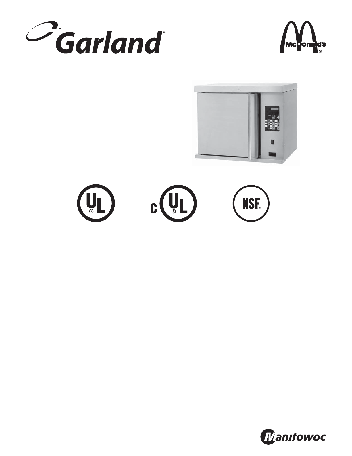
INSTALLATION, OPERATING
INSTRUCTIONS & PART LIST
FOR THE GARLAND
HALF-SIZE, ELECTRIC
CONVECTION OVEN,
MODEL: MCOE5L
WARNING:
IMPROPER INSTALLATION, ADJUSTMENT, ALTERATION, SERVICE OR MAINTENANCE CAN CAUSE
PROPERTY DAMAGE, INJURY OR DEATH. READ THE INSTALLATION, OPERATING AND MAINTENANCE
INSTRUCTIONS THOROUGHLY BEFORE INSTALLING OR SERVICING THIS EQUIPMENT.
NOTE:
OVEN WILL PRODUCE A QUANTITY OF SMOKE UPON INITIAL FIRE UP. THIS “BURN OFF” MAY LAST
IN EXCESS OF 10-20 MINUTES.
PLEASE READ ALL SECTIONS OF THIS MANUAL AND RETAIN FOR FUTURE REFERENCE.
THIS EQUIPMENT MUST BE INSTALLED AND COMMISSIONED BY A PROFESSIONAL,
FACTORY-TRAINED TECHNICIAN.
NOTE: This manual pertains to all oven models listed above. The reader/operator must interpret its
contents to applicable needs. If you have questions about any instructional materials pertaining to Garland
convection ovens, please contact our Customer Service Department at one of the phone numbers below.
MANUFACTURED EXCLUSIVELY FOR McDonald's BY
CLEVELAND RANGE
1333 EAST 179 St., CLEVELAND, OH 44110
MCD HOTLINE TOLL FREE: (800) 446-8367 PHONE: (800) 424-2411 FAX: (888) 606-0460
E-mail: clamshell@garland-group.com
http://www.garland-group.com
Part # 4516833 Rev A (20 Sep 2011)
Page 2

Page 3

GARLAND HALF SIZE ELECTRIC CONVECTION OVEN MODEL MCOE5L INSTALLATION/OPERATION MANUAL
TABLE OF CONTENTS
DIMENSIONS AND SPECIFICATIONS . . . . . . . . . . . . . . . . . . . . . . . . . . . . . . . . . . . . . . . . . . . . . . . . . . . . 4
INSTALLATION . . . . . . . . . . . . . . . . . . . . . . . . . . . . . . . . . . . . . . . . . . . . . . . . . . . . . . . . . . . . . . . . . . . . . . . . 5
Electrical Connection . . . . . . . . . . . . . . . . . . . . . . . . . . . . . . . . . . . . . . . . . . . . . . . . . . . . . . . . . . . . . . . . . . . . . . . . . . . . . . . . . . . . . . . . . . . . . . .5
DESCRIPTION OF OVEN CONTROLS . . . . . . . . . . . . . . . . . . . . . . . . . . . . . . . . . . . . . . . . . . . . . . . . . . . . . 6
OPERATING INSTRUCTIONS . . . . . . . . . . . . . . . . . . . . . . . . . . . . . . . . . . . . . . . . . . . . . . . . . . . . . . . . . . . . 7
To turn oven ON . . . . . . . . . . . . . . . . . . . . . . . . . . . . . . . . . . . . . . . . . . . . . . . . . . . . . . . . . . . . . . . . . . . . . . . . . . . . . . . . . . . . . . . . . . . . . . . . . . . .7
Preheat. . . . . . . . . . . . . . . . . . . . . . . . . . . . . . . . . . . . . . . . . . . . . . . . . . . . . . . . . . . . . . . . . . . . . . . . . . . . . . . . . . . . . . . . . . . . . . . . . . . . . . . . . . . . .7
To Select a menu item . . . . . . . . . . . . . . . . . . . . . . . . . . . . . . . . . . . . . . . . . . . . . . . . . . . . . . . . . . . . . . . . . . . . . . . . . . . . . . . . . . . . . . . . . . . . . . 7
To begin a cook cycle or start a bake cycle . . . . . . . . . . . . . . . . . . . . . . . . . . . . . . . . . . . . . . . . . . . . . . . . . . . . . . . . . . . . . . . . . . . . . . . . . . . 7
To cancel a cook cycle or cancel a bake . . . . . . . . . . . . . . . . . . . . . . . . . . . . . . . . . . . . . . . . . . . . . . . . . . . . . . . . . . . . . . . . . . . . . . . . . . . . . .7
Pro le Baking. . . . . . . . . . . . . . . . . . . . . . . . . . . . . . . . . . . . . . . . . . . . . . . . . . . . . . . . . . . . . . . . . . . . . . . . . . . . . . . . . . . . . . . . . . . . . . . . . . . . . . . 7
Hold Timer . . . . . . . . . . . . . . . . . . . . . . . . . . . . . . . . . . . . . . . . . . . . . . . . . . . . . . . . . . . . . . . . . . . . . . . . . . . . . . . . . . . . . . . . . . . . . . . . . . . . . . . . .7
Recovery Timer . . . . . . . . . . . . . . . . . . . . . . . . . . . . . . . . . . . . . . . . . . . . . . . . . . . . . . . . . . . . . . . . . . . . . . . . . . . . . . . . . . . . . . . . . . . . . . . . . . . . . 7
Fast Cool . . . . . . . . . . . . . . . . . . . . . . . . . . . . . . . . . . . . . . . . . . . . . . . . . . . . . . . . . . . . . . . . . . . . . . . . . . . . . . . . . . . . . . . . . . . . . . . . . . . . . . . . . . .7
PROGRAM LOGIC. . . . . . . . . . . . . . . . . . . . . . . . . . . . . . . . . . . . . . . . . . . . . . . . . . . . . . . . . . . . . . . . . . . . . . 8
CONTROL PROGRAMMING . . . . . . . . . . . . . . . . . . . . . . . . . . . . . . . . . . . . . . . . . . . . . . . . . . . . . . . . . . . . . 9
To change the Cancel Alarm . . . . . . . . . . . . . . . . . . . . . . . . . . . . . . . . . . . . . . . . . . . . . . . . . . . . . . . . . . . . . . . . . . . . . . . . . . . . . . 9
To change the Cook Temperature . . . . . . . . . . . . . . . . . . . . . . . . . . . . . . . . . . . . . . . . . . . . . . . . . . . . . . . . . . . . . . . . . . . . . . . . . . . . . . . . . . . 9
To change the Cook Time . . . . . . . . . . . . . . . . . . . . . . . . . . . . . . . . . . . . . . . . . . . . . . . . . . . . . . . . . . . . . . . . . . . . . . . . . . . . . . . . . . . . . . . . . . .9
To Change the Fan Speed . . . . . . . . . . . . . . . . . . . . . . . . . . . . . . . . . . . . . . . . . . . . . . . . . . . . . . . . . . . . . . . . . . . . . . . . . . . . . . . . . . . . . . . . . . . 9
To Change the Flex Time . . . . . . . . . . . . . . . . . . . . . . . . . . . . . . . . . . . . . . . . . . . . . . . . . . . . . . . . . . . . . . . . . . . . . . . . . . . . . . . . . . . . . . . . . . . .9
To change the Hold Time. . . . . . . . . . . . . . . . . . . . . . . . . . . . . . . . . . . . . . . . . . . . . . . . . . . . . . . . . . . . . . . . . . . . . . . . . . . . . . . . . . . . . . . . . . .10
To change the Product Name . . . . . . . . . . . . . . . . . . . . . . . . . . . . . . . . . . . . . . . . . . . . . . . . . . . . . . . . . . . . . . . . . . . . . . . . . . . . . . . . . . . . . .10
To View Recovery Information. . . . . . . . . . . . . . . . . . . . . . . . . . . . . . . . . . . . . . . . . . . . . . . . . . . . . . . . . . . . . . . . . . . . . . . . . . . . . . . . . . . . . .10
Control Safety Features . . . . . . . . . . . . . . . . . . . . . . . . . . . . . . . . . . . . . . . . . . . . . . . . . . . . . . . . . . . . . . . . . . . . . . . . . . . . . . . . . . . . . . . . . . . .11
To reset factory defaults. . . . . . . . . . . . . . . . . . . . . . . . . . . . . . . . . . . . . . . . . . . . . . . . . . . . . . . . . . . . . . . . . . . . . . . . . . . . . . . . . . . . . . . . . . . .11
MAINTENANCE & TROUBLESHOOTING . . . . . . . . . . . . . . . . . . . . . . . . . . . . . . . . . . . . . . . . . . . . . . . . . 11
Factory Default Menu Items. . . . . . . . . . . . . . . . . . . . . . . . . . . . . . . . . . . . . . . . . . . . . . . . . . . . . . . . . . . . . . . . . . . . . . . . . . . . . . . . . . . . . . . .11
Check Calibration. . . . . . . . . . . . . . . . . . . . . . . . . . . . . . . . . . . . . . . . . . . . . . . . . . . . . . . . . . . . . . . . . . . . . . . . . . . . . . . . . . . . . . . . . . . . . . . . . .12
Break-In Period . . . . . . . . . . . . . . . . . . . . . . . . . . . . . . . . . . . . . . . . . . . . . . . . . . . . . . . . . . . . . . . . . . . . . . . . . . . . . . . . . . . . . . . . . . . . . . . . . . . .12
Exterior Cleaning . . . . . . . . . . . . . . . . . . . . . . . . . . . . . . . . . . . . . . . . . . . . . . . . . . . . . . . . . . . . . . . . . . . . . . . . . . . . . . . . . . . . . . . . . . . . . . . . . .12
Blower Wheel & Temperature Probe . . . . . . . . . . . . . . . . . . . . . . . . . . . . . . . . . . . . . . . . . . . . . . . . . . . . . . . . . . . . . . . . . . . . . . . . . . . . . . . .13
Motor Care . . . . . . . . . . . . . . . . . . . . . . . . . . . . . . . . . . . . . . . . . . . . . . . . . . . . . . . . . . . . . . . . . . . . . . . . . . . . . . . . . . . . . . . . . . . . . . . . . . . . . . . .13
PARTS ID: OVEN EXTERIOR; ALL MODELS. . . . . . . . . . . . . . . . . . . . . . . . . . . . . . . . . . . . . . . . . . . . . . . . . . . . . . . 14
PARTS ID: CARD READER ASSY; ALL MODELS . . . . . . . . . . . . . . . . . . . . . . . . . . . . . . . . . . . . . . . . . . . . . . . . . . . 16
PARTS ID: SIDE PARTITION ASSY; ALL MODELS . . . . . . . . . . . . . . . . . . . . . . . . . . . . . . . . . . . . . . . . . . . . . . . . . 16
PARTS ID: CONTROL PANEL ASSY; ALL MODELS. . . . . . . . . . . . . . . . . . . . . . . . . . . . . . . . . . . . . . . . . . . . . . . . . 17
PARTS ID: ELEMENT ASSY; ALL MODELS. . . . . . . . . . . . . . . . . . . . . . . . . . . . . . . . . . . . . . . . . . . . . . . . . . . . . . . . 17
PARTS ID: DOOR ASSY; ALL MODELS . . . . . . . . . . . . . . . . . . . . . . . . . . . . . . . . . . . . . . . . . . . . . . . . . . . . . . . . . . . 18
PARTS ID: BAFFLE ASSY; ALL MODELS . . . . . . . . . . . . . . . . . . . . . . . . . . . . . . . . . . . . . . . . . . . . . . . . . . . . . . . . . 18
PARTS ID: WIRING HARNESS ASSY . . . . . . . . . . . . . . . . . . . . . . . . . . . . . . . . . . . . . . . . . . . . . . . . . . . . . . . . . . . . . 19
WIRING DIAGRAM; ALL MODELS . . . . . . . . . . . . . . . . . . . . . . . . . . . . . . . . . . . . . . . . . . . . . . . . . . . . . . . . . . . . . . 20
Part # 4516833 Rev A (20 Sep 2011)
Page 3
Page 4
INSTALLATION/OPERATION MANUAL GARLAND HALF SIZE ELECTRIC CONVECTION OVEN MODEL MCOE5L
DIMENSIONS AND SPECIFICATIONS
21.000"
[535 mm]
OVEN
INTERIOR
30.500"
[775 mm]
25.250"
[645 mm]
30.250"
[766 mm]
20.000
[510 mm]
OVEN
25.750"
[657 mm]
INTERIOR
15.500"
[393 mm]
OVEN INTERIOR
Element
Package
Standard 8.0 38.5 33.3 20.8 23.0 23.0 18.0 20.0 20.0 34.8 13.1 10.9 10.9
Electrical speci cations include motor requirements. Double-deck models require 2 separate power supplies.
Sides Rear Crated Uncrated
1” (25mm) 1” (25mm) 36” (914mm) 31” (787mm) 350lbs. (159Kg)
Total
kW
208V/1Ph 240V/1Ph
Clearances
208V/3Ph 240V/3Ph
XYZXYZ XY Z
Nominal Amperes Per Line
Shipping WeightCombustible Wall Entry
240V/1Ph
230V /3Ph N 400V
Page 4
Part # 4516833 Rev A (20 Sep 2011)
Page 5
GARLAND HALF SIZE ELECTRIC CONVECTION OVEN MODEL MCOE5L INSTALLATION/OPERATION MANUAL
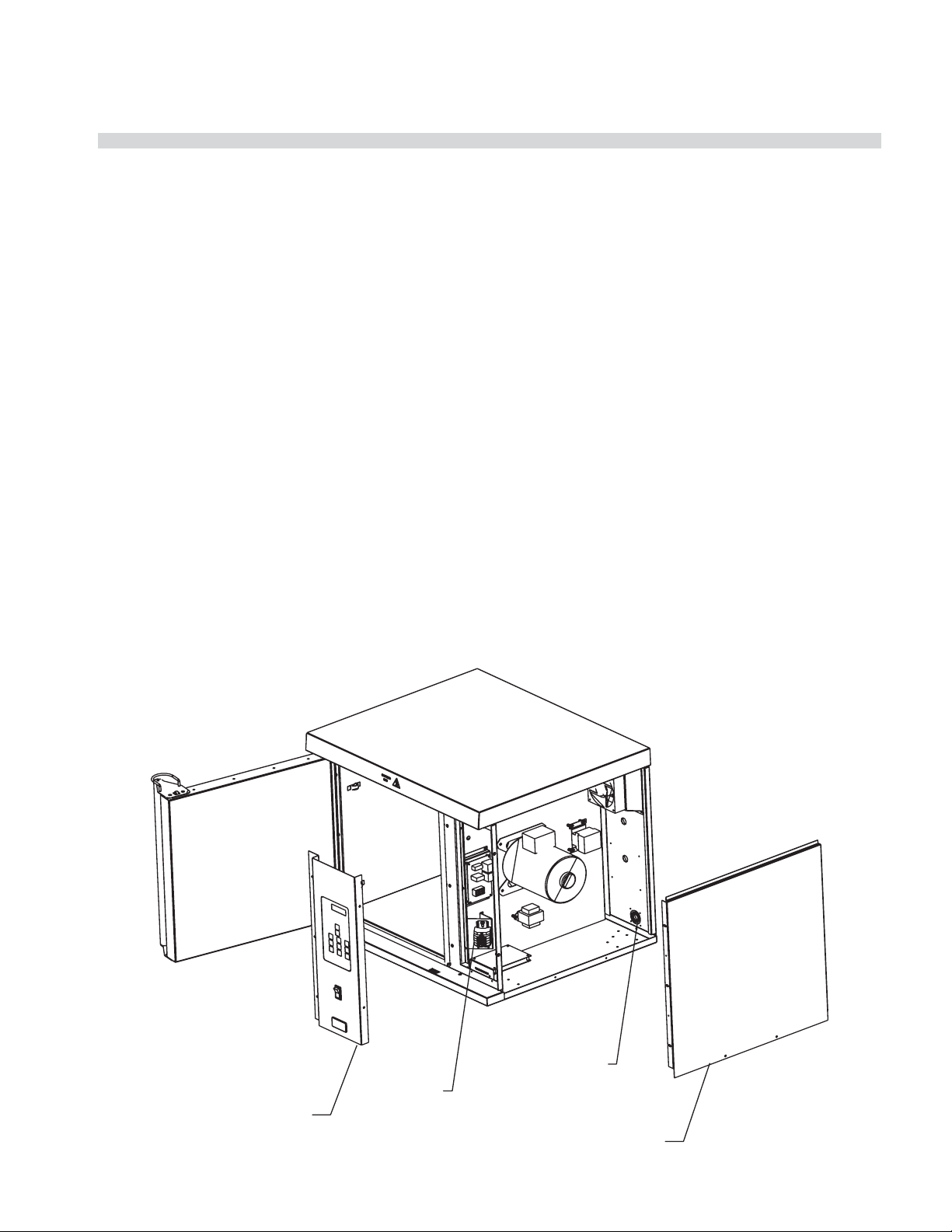
INSTALLATION
Proper placement of the oven will ensure operator
convenience and satisfactory performance.
Adequate clearance must be provided for cleaning,
servicing, and proper operation. (Refer to chart on page 4
for minimum clearances.)
enough length to reach the terminal block.
6. Strip just enough wire to insert into the terminal block.
7. Tighten terminal block screws and the screws in the BX
to clamp the cord.
Electrical Connection
Before attempting the electrical connection, the rating
plate should be checked to con rm that the oven’s
electrical characteristics and the electrical supply are
compatible. The plate is located on the inside surface of
the control panel/body side.
1. Open the oven door to reveal the control panel
mounting screws.
2. Remove all screws attaching the control panel
assembly to the oven.
3. Next remove the screws mounting the body side to the
oven in the front and back.
4. Remove the knockout plate at the rear of the oven and
mount the appropriate Size BX connector to fasten the
cord. Re-attach the knockout to the oven.
5. Pass the cord through the bx connector leaving
8. Verify all electrical connections are correct. Re-attach
the body side and control panel assembly.
Visually inspect all electrical connections. A wiring diagram
is a xed to the inside surface of the control panel/body
side section.
Installation of the wiring must be made in accordance with
UL 197, Commercial Electric Cooking Appliance Standards,
local codes, and the National Electrical Code, ASNI/NFPA 70-
1990, in regard to:
a. Switch panel size
b. Overload protection
c. Wire type
d. Wire size
e. Temperature limitations of wires
f. Method of connection, (conduit, cable, etc.)
CONTROL PANEL
ASSEMBLY
Part # 4516833 Rev A (20 Sep 2011)
KNOCKOUT
PLATE
TERMINAL
BLOCK
BODY SIDE
Page 5
Page 6
INSTALLATION/OPERATION MANUAL GARLAND HALF SIZE ELECTRIC CONVECTION OVEN MODEL MCOE5L
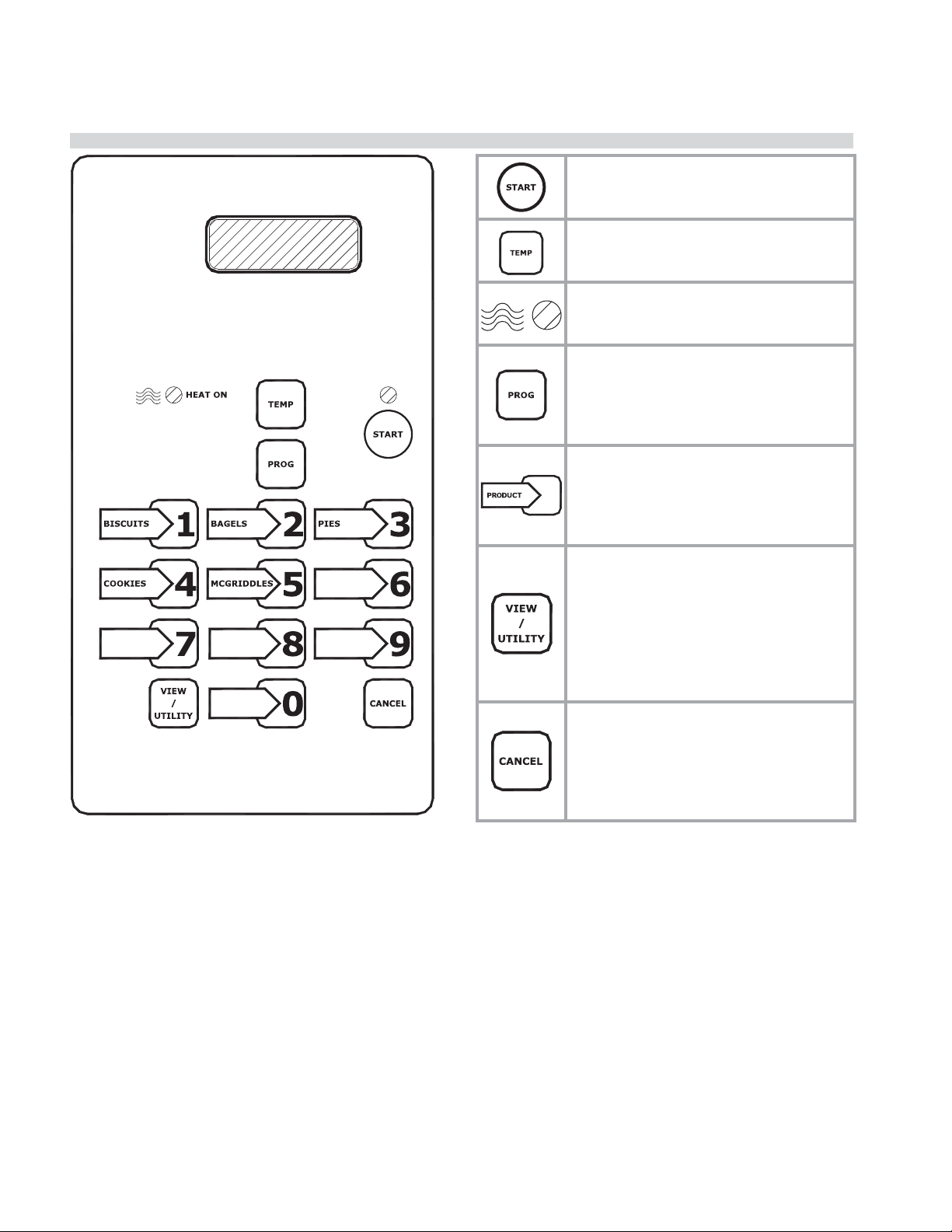
DESCRIPTION OF OVEN CONTROLS
Power Button – The START button is
used to begin a bake. The led lights to
indicate the bake has been started.
TEMP Button – The TEMP button is used
to verify the actual temp and setpoint
temp.
Heat On LED – The HEAT ON LED lights
to indicate that the control called for
heat.
Program Button – The PROG button
allows each button to be programed
with the various functions of the control.
Press and hold the PROG button to enter
the programming mode.
Product Button(s) – The PRODUCT keys
are used to select pre-programmed time
and temperature for speci c products.
Up to 10 di erent product buttons can
be programmed.
VIEW / UTILITY Button – The VIEW/
UTILITY button toggles the display when
baking multiple products at the same
time. Press the view/utility button and
the display will show the product names
and time left for each product currently
baking in the oven. Allows the user to
enter FAST COOL
CANCEL Button – The CANCEL button
allows the user to end a bake. Press and
hold the button, the control will beep
when the button is pressed and again
when the bake is cancelled. The last
bake entered will be cancelled.
Page 6
Part # 4516833 Rev A (20 Sep 2011)
Page 7

GARLAND HALF SIZE ELECTRIC CONVECTION OVEN MODEL MCOE5L INSTALLATION/OPERATION MANUAL
OPERATING INSTRUCTIONS
To turn oven ON
The Main Power Switch – Controls power to the oven
and must be turned ON to start operation. The controller
display will be active and default to product “BISCUITS”
(Product Key 1).
Preheat
The oven will preheat to the set temperature of Product
Key 1 (Note: Factory default for Product Key 1 is BISCUITS Oven set temperature 375°F).
During this preheat mode, the controller will display “TOO
COOL”. “TOO COOL” will appear in the display while the
temperature is greater than 25°F below set temperature
AND for 10 minutes upon reaching set temperature from
initial power up. “TOO HOT” will be displayed when the
control is 250 F above the set temperature.
To Select a menu item
To select a menu item, simply press the desired menu item
number button.
To begin a cook cycle or start a bake cycle
To start a bake for a selected menu item, press the
button. The product name and the remove time
programmed will be displayed. The countdown of the
programmed time for that product will start and a number
“1” will be displayed in the lower right hand corner of the
screen to indicate that there 1 product baking at that time.
The number will update as subsequent cook cycles are
started.
“beep” sounds. Another “beep” sounds when the timer is
cancelled. The CANCEL button works in the order of the
last product entered, i.e. Biscuits are timing and bagels
are started accidentally. Bagels will be cancelled rst, then
biscuits.
Once a timer has completed counting down, the display
will default back to the menu item programmed in
PRODUCT KEY 1 (Most often Biscuits).
Pro le Baking
Pro le Baking is only available in software & ash
numbers 240-91018-05-XX. With pro le baking,
menu items can be programmed with up to 4 stages of
functional changes. The following menu item functions
are available with up to 4 stages:
• FAN CYCLE
• COOK TEMP
• COOK TIME
• FAN SPEED
• FLEX TIME
FAN CYCLE – The Fan Cycle function has 2 options:
FULL - The convection fan is constant on
HEAT – The convection fan is only on during the heat
cycle.
Hold Timer
The hold timer is a separate timer that counts down within
the control and is HIDDEN from the display. The hold timer
alerts the operator when product is available to be served
after cooling down. This timer is most often used for
cooling pies.
Flex Time – Included in this oven is a feature called “FLEX
TIME”. Flex time is a feature which when a product bake
timer is counting down, the operator may notice the time
either slowing down or speeding up. The “ ex time” is
based on the temperature drop in the oven over a period
of time. Larger bake sizes (i.e. full tray of Mu ns) will have
a slower time where as smaller bake sizes will have a faster
time.
During baking, press the button to display the product
name and the time remaining before removal.
NOTE: The oven is designed to bake batches of di erent
sizes using the same time settings.
To cancel a cook cycle or cancel a bake
To cancel a bake, the user presses and holds the
button. Immediately upon pressing the button, an audible
Part # 4516833 Rev A (20 Sep 2011)
Recovery Timer
Built into this control is a recovery timer. This timer is a
stored value from when the oven last rise in temperature
from 150°F to 250°F. The value of this number should
generally be “1:00” to “1:30” indicating that it took
between 1 minute and 1 minute and 30 seconds to rise
in temperature between 150°F to 250°F. A value outside
this parameter may indicate a potential or future heating
problem.
Fast Cool
The fast cool feature when activated cools the oven down
in a rapid manner while the door is open. Press the VIEW/
UTILITY button and then press the START button.
Page 7
Page 8

INSTALLATION/OPERATION MANUAL GARLAND HALF SIZE ELECTRIC CONVECTION OVEN MODEL MCOE5L
PROGRAM LOGIC
Press & Hold
(3 seconds)
SELECT PRODUCT ->
Select
product
SELECT PRODUCT ->
PRODUCT NAME SELECTED
MAIN MENU
EDIT MENU ITEM
Scroll
Forward
Scroll
Backward
MAIN MENU
SYSTEM INFO
MAIN MENU
SERVICE MENU
RECOVERY
FLASH NUMBER
SOFTWARE NUMBER
DOWNLOAD NUMBER
ADDRESS
SHELF ID
DOOR ALARM
Page 8
CANCEL
COOK TEMP T1
COOK TIME T1
FAN SPEED T1
FAN CYCLE T1
FLEX TIME T1
COOK TEMP T2
COOK TIME T2
FAN SPEED T2
FAN CYCLE T2
FLEX TIME T2
HOLD TIME
PRODUCT NAME
TEMP DISPLAY
CAL OFFSET
SETBACK TIME
FACTORY DEFAULTS
Shown Only in FLASH
Number 240-91018-05-1
NOTE: T2, T3, T4 are
programmed stages and
will only appear when the
previous stage has
programmed settings
Part # 4516833 Rev A (20 Sep 2011)
Page 9

GARLAND HALF SIZE ELECTRIC CONVECTION OVEN MODEL MCOE5L INSTALLATION/OPERATION MANUAL
CONTROL PROGRAMMING
To change the Cancel Alarm
1. PRESS the button for approximately 3 seconds. The
control will display “MAIN MENU | EDIT MENU ITEM”.
2. PRESS the button 1x. The control will display
“SELECT PRODUCT->”.
3. Using buttons through , select the product that
requires a programming change. The control will
display that menu item.
4. PRESS the button 1x. The control will display
“CANCEL”.
5. PRESS the or button to change the current
setting.
6. PRESS the button to save the new setting.
7. PRESS the button 2x to exit the programming
mode.
To change the Cook Temperature
1. PRESS the button for approximately 3 seconds. The
control will display “MAIN MENU | EDIT MENU ITEM”.
2. PRESS the button 1x. The control will display
“SELECT PRODUCT->”.
3. Using buttons through , select the product that
requires a programming change. The control will
display that menu item.
3. Using buttons through , select the product that
requires a programming change. The control will
display that menu item.
4. PRESS the button until the control displays “COOK
TIME (T1, T2, T3, T4)” .
5. Using buttons through , enter the new setting to
change the current setting.
6. PRESS the button to save the new setting.
7. PRESS the button 2x to exit the programming
mode..
To Change the Fan Speed
1. PRESS the button for approximately 3 seconds. The
control will display “MAIN MENU | EDIT MENU ITEM”.
2. PRESS the button 1x. The control will display
“SELECT PRODUCT->”.
3. Using buttons through , select the product that
requires a programming change. The control will
display that menu item.
4. PRESS the button until the control displays “FAN
SPEED (T1, T2, T3, T4)”.
5. PRESS the or button to change the current
setting (HIGH OR LOW).
6. PRESS the button to save the new setting.
4. PRESS the button until the control displays “COOK
TEMPERATURE (T1, T2, T3, T4)”.
5. Using buttons
change the current setting.
6. PRESS the
7. PRESS the button 2x to exit the programming
mode..
through , enter the new setting to
button to save the new setting.
To change the Cook Time
1. PRESS the button for approximately 3 seconds. The
control will display “MAIN MENU | EDIT MENU ITEM”.
2. PRESS the button 1x. The control will display
“SELECT PRODUCT->”.
Part # 4516833 Rev A (20 Sep 2011)
7. PRESS the button 2x to exit the programming
mode..
To Change the Flex Time
1. PRESS the button for approximately 3 seconds. The
control will display “MAIN MENU | EDIT MENU ITEM”.
2. PRESS the button 1x. The control will display
“SELECT PRODUCT->”.
3. PRESS the or button to change the current
setting.
4. PRESS the button until the control displays “FLEX
TIME (T1, T2, T3, T4)”.
5. PRESS the or button to change the current
Page 9
Page 10

INSTALLATION/OPERATION MANUAL GARLAND HALF SIZE ELECTRIC CONVECTION OVEN MODEL MCOE5L
CONTROL PROGRAMMING
setting (YES or NO).
6. PRESS the
button to save the new setting.
7. PRESS the button 2x to exit the programming
mode..
To Change the Fan Cycle
1. PRESS the button for approximately 3 seconds. The
control will display “MAIN MENU | EDIT MENU ITEM”.
2. PRESS the button 1x. The control will display
“SELECT PRODUCT->”.
3. PRESS the or button to scroll through the list of
available menu item names.
1. PRESS the button for approximately 3 seconds. The
control will display “MAIN MENU | EDIT MENU ITEM”.
2. PRESS the button 1x. The control will display
“SELECT PRODUCT->”.
3. Using buttons through , select the product that
requires a programming change. The control will
display that menu item.
4. PRESS the button until the control displays “FAN
CYCLE (T1, T2, T3, T4)”.
5. PRESS the or button to change the current
setting.
6. PRESS the button to save the new setting.
7. PRESS the button 2x to exit the programming
mode..
To change the Hold Time
1. PRESS the button for approximately 3 seconds. The
control will display “MAIN MENU | EDIT MENU ITEM”.
2. PRESS the button 1x. The control will display
“SELECT PRODUCT->”.
Available Menu items names
Bacon Bagels BB Mu n
Buscuits Bread Casserole
Chicken Chicken II Cookies
Eggs McGriddle Meatloaf
Mu n New Item 0 New Item 1
New Item 2 New Item 3 New Item 4
New Item 5 New Item 6 New Item 7
New Item 8 New Item 9 Pancake
Pasta Pastry Pies
Potato Bake Pretzels Sausage
Scratch Biscuit Stu ng
4. PRESS the button until the control displays
“PRODUCT NAME”
5. Using buttons through , enter the new setting to
change the current setting.
6. PRESS the button to save the new setting.
7. PRESS the button 2x to exit the programming
mode.
To View Recovery Information
3. Using buttons through , select the product that
requires a programming change. The control will
display that menu item.
4. PRESS the
button until the control displays “HOLD
TIME”
5. Using buttons
through , enter the new setting to
change the current setting (Note: a number of 00:00
turns the hold timer OFF”).
6. PRESS the
7. PRESS the
button to save the new setting.
button 2x to exit the programming
mode..
To change the Product Name
Page 10
1. PRESS the button for approximately 3 seconds. The
control will display “MAIN MENU | EDIT MENU ITEM”.
2. PRESS the or button to scroll to “SYSTEM INFO”.
3. PRESS the button until the control displays
“RECOVERY”
4. PRESS the button 2x to exit the programming
mode..
Control Safety Features
Part # 4516833 Rev A (20 Sep 2011)
Page 11

GARLAND HALF SIZE ELECTRIC CONVECTION OVEN MODEL MCOE5L INSTALLATION/OPERATION MANUAL
MAINTENANCE & TROUBLESHOOTING
“Heater Error”
• If the control is calling for heat and doesn’t
see one, (1), degree of temperature rise over
a period of 5 minutes. Turn the main power
switch o for approximately 10 seconds to
reset the control. If problem persists, contact
service.
“High Temp”
• If the oven malfunctions, and the elements
continuously run until the temperature probe
reads 575°F, the element relay will be closed
and the display will read “High Temp”:
To reset factory defaults
Factory Default Menu Items
1. PRESS the button for approximately 3 seconds. The
control will display “MAIN MENU | EDIT MENU ITEM”.
2. PRESS the or button to scroll to “SERVICE MENU”.
3. PRESS the button until the control displays
“FACTORY DEFAULTS”
4. PRESS the or button to change the “NO” to “YES”
5. PRESS the button 1X. The control will not respond
for a period of approximately 5 seconds while the
control defaults are loading.
6. PRESS the button 1X.
7. PRESS the button 2x to exit the programming
mode..
Select Product ->
CANCEL
COOK TEMP T 1
COOK TIME T 1
FAN SPEED T 1
FAN CYCLE T 1
FLEX TIMING T 1
COOK TEMP T 2
COOK TIME T 2
FAN SPEED T 2
FAN CYCLE T 2
FLEX TIMING T2
COOK TEMP T 3
COOK TIME T 3
FAN SPEED T 3
FAN CYCLE T 3
FLEX TIMING T3
COOK TEMP T 4
COOK TIME T 4
FAN SPEED T 4
FAN CYCLE T 4
FLEX TIMING T4
HOLD TIME
Product 1 Product 2 Product 3 Product 4 Product 5 Product 6 Product 7 Product 8 Product 9 Product 10
BISCUITS BAGELS PIES COOKIES MCGRIDDLE MUFFINS PASTRY BITES NEW ITEM 8 NEW ITEM 9 NEW ITEM 0.1
“MANUAL” “MANUAL” “MANUAL” MANUAL MANUAL MANUAL MANUAL MANUAL MANUAL MANUAL
375F 375F 375F 375F 375F 360F 350F 375F 375F 375F
4:45 3:00 11:00 2:00 6:00 :30 3:00 0:00 0:00 0:00
HIGH HIGH HIGH HIGH HIGH LOW LOW HIGH HIGH HIGH
FULL FULL FULL FULL FULL FULL FULL FULL FULL FULL
YES YES YES YES YES NO NO YES YES YES
375F 375F 375F 375F 375F 305F 350F
0 0 0 0 0 27:30 11:00
HIGH HIGH HIGH HIGH HIGH LOW LOW
FULL FULL FULL FULL FULL HEAT HEAT
YES YES YES YES FLEX NO NO
375F 375F 375F 375F 375F 310F 350F
0:00 0:00 0:00 0:00 0:00 19:00 6:00
HIGH HIGH HIGH HIGH HIGH LOW LOW
FULL FULL FULL FULL FULL FULL FULL
YES FLEX FLEX FLEX FLEX NO NO
375F 375F 375F 375F 375F 375F 375F
0:00 0:00 0:00 0:00 0:00 0:00 0:00
HIGH HIGH HIGH HIGH HIGH LOW LOW
FULL FULL FULL FULL FULL FULL FULL
YES FLEX FLEX FLEX FLEX NO NO
0:00 0:00 0:00 0:00 0:00 0:00 0:00 0:00 0:00 0:00
Part # 4516833 Rev A (20 Sep 2011)
Page 11
Page 12

INSTALLATION/OPERATION MANUAL GARLAND HALF SIZE ELECTRIC CONVECTION OVEN MODEL MCOE5L
MAINTENANCE & TROUBLESHOOTING
Check Calibration
Tools: digital thermometer with probe, oven mitt.
1. Clamp the probe in the center of the middle rack. Pass
the probe wire out of the oven between the door and
the door seal and close the oven door. Plug the probe
wire into the thermometer.
2. Press the oven on/o switch.
3. Allow the oven to preheat to 375°F for approx. 30
minutes before calibrating.
4. Record the values displayed on the thermometer when
the HEAT ON LED goes o , and again when it goes back
on. The average of these 2 numbers is the temperature
at which the oven is cycling. This is the value used to
calibrate the oven.
5. To begin programming, press and hold the PROG
button until the display changes to main menu/edit
menu item.
6. Press the 2 or 8 button to toggle through main menu to
service menu.
7. Pressing the PROG button again will advance to
CAL/OFFSET. The 2 or 8 buttons can be used to
increment the o set by 1 degree per button push.
The o set can be + or -. The factory default will be 0,
(no o set). If there is already o set programmed, add
or subtract the number found in Step 4 to/from the
existing o set. Press the PROG button and then the
start button to exit the service menu program mode
and nish the calibration.
Example: Recorded temp: 380°F, (step 4), set temp: 375°f—
the o set would be +5 to calibrate. Subtract the set temp
from the recorded value and that will give the +/- value to
use (380-375=+5).
Maximum o set of +/- 50°f can be entered in calibration
mode
8. After entering a calibration o set, if necessary, allow
the unit to cycle and verify calibration by repeating
Step 4. The value found in Step 4 should match the set
temperature.
9. Press the VIEW/UTILITY button, then START to put the
unit into the FAST COOL mode.
10. Wait 3 minutes with oven in FAST COOL, then
using an oven mitt, remove the oven probe.
Break-In Period
When oven is new, operate it for one hour at 375°F before
you begin your normal cooking operation. After cooling,
wipe the interior, including the racks, with a clean damp
cloth.
NOTE: Disconnect the oven from its from power supply
before cleaning or servicing.
Exterior Cleaning
Establish a regular schedule. Any spills should be wiped o
immediately.
1. The oven should always be allowed to cool
su ciently,using FAST COOL, before any cleaning is
attempted. See “VIEW/UTILITY Button” on Page 12.
2. Wipe exposed, cleanable surface when cool with a mild
detergent and hot water. Stubborn residue spots may
be removed with a lightweight non-metallic scouring
pad. Dry thoroughly with a clean cloth.
3. Stainless Steel surfaces can often be cleaned
adequately with the same method. Stubborn stains
may be removed by using a non-metallic abrasive
pad, rubbing in the direction of the metal’s grain. If
necessary, for particularly heavy deposits, you may mix
a thin paste of water and scouring powder, and apply
it with a sponge. Be careful to apply light pressure and
remember to rub only in the direction of the grain in
the metal.
4. The control panel surface is easily cleaned with hot
water, soap and a soft cloth. Do not use hard abrasives,
solvent type materials or metallic scouring pads since
these will scratch or cloud the surface.
5. Never spray the perforated areas or control panel
with steam or water, as this will allow moisture into
the control cavity, which could damage electrical
components.
Page 12
Part # 4516833 Rev A (20 Sep 2011)
Page 13

GARLAND HALF SIZE ELECTRIC CONVECTION OVEN MODEL MCOE5L INSTALLATION/OPERATION MANUAL
Procedure is complete.
MAINTENANCE & TROUBLESHOOTING
Blower Wheel & Temperature Probe
Tools: brush, cloth.
1. Unplug the unit from the receptacle.
2. Remove the racks, right rack guide and the ba e.
3. Brush the wheel as needed to remove any grease and/
or particles.
4. Carefully wipe the blower wheel and temp probe clean
with a damp cloth.
5. Replace the ba e, rack guide and racks.
INSIDE OVEN
RACK SUPPORT
Motor Care
The motor on your convection oven is maintenance free
since it is constructed with self-lubricating sealed ball
bearings. It is designed to provide durable service when
treated with ordinary care.
We have a few suggestions to follow on the care of
your motor. When the motor is operating, it cools itself
internally by air entering at the rear of the motor case,
provided proper clearance has been allowed. Since
the blower wheel is in the oven cavity it is at the same
temperature as the oven. If the motor is stopped while the
oven is hot, the heat from the blower wheel is conducted
down the shaft and into the armature of the motor. This
action could shorten the life of the motor.
We recommend, at the end of the bake or roasting period,
when the oven will be idle for any period of time, or before
shutting down completely, that the doors be left open
slightly, and press the VIEW/UTILITY button on the control
panel. The fan will continue to run until the oven cools
down to 150°F (66°C). When the oven temperature drops
below 150ºF (66ºC) turn the oven o using the ON/OFF
switch. This feature protects the oven motor from premature failure. Optimal cool-down will be achieved with
the door open slightly.
Part # 4516833 Rev A (20 Sep 2011)
Page 13
Page 14

INSTALLATION/OPERATION MANUAL GARLAND HALF SIZE ELECTRIC CONVECTION OVEN MODEL MCOE5L
PARTS ID: OVEN EXTERIOR; ALL MODELS
1
2
35C
41
13
12
11
30
16
10
32
31
33
7
8
9
34
27
28
3
29
4
5
26
25
35B
35A
24
15
23
Page 14
14
17
18
19
20
36
21
22
37
Oven Exterior
Part # 4516833 Rev A (20 Sep 2011)
6
Page 15

GARLAND HALF SIZE ELECTRIC CONVECTION OVEN MODEL MCOE5L INSTALLATION/OPERATION MANUAL
PARTS ID: OVEN EXTERIOR; ALL MODELS
Item Part # Description
1 1960901 Main Top MCOE5L
2 1960902 Cover, Micro Switch Access
3 1960502 Flue Box MCOE5
4 1961199 Partition Side Assembly
5 1671101 Fan - 110MM, 208/240 V
6 1951402 Body Side, CNTRL
7 CK1385497 Hinge Bracket Assembly
8 1011201 Steel Tubing Chrome Spacer
9 1951401 Body Side, Oven
10 1960709 Ba e MTG BRKT
11 1766001 Oven Rack
12 1966503 Door Seal MCOE5
13 1766004 Rack Guide
14 1962199 Oven Door MCOE5
15 1966501 Door Seal RT Silicon
16 1966502 Door Seal Top / Bottom Silicon
17
18 1960797 Ba e Assembly
19
20 1962299 Card Reader Assembly
21 4519657 Blower Wheel Assembly Includes Wheel Puller, Spacers & Fasteners
22 1951502 Motor 208-240 1/3 HP 5/8 Shaft
23 1027801 Swivel Caster with wheel lock
24 1027800 Swivel Caster W/O lock
25 1028500 3/8 x 90 BX Connector
26 1960504 BX Cable 15 3/8”
27 1960503 High Limit Cover
28 4520416 High Limit 135C Degree (275 F)
29 1028501 3/8 BX connector
30 CK1962196 Micro Switch Bracket Assembly Complete
31 9006401 Switch-Mini Snap Hi-Temp 1 Amp.
32 8003221 4-40x1 PH Pan HD M/S ZC
33 8001505 4-40 Keps Nut ZC
34 1750501 Door Catch
35A CK4529043 Plug and Cord, 208/240V -3Ph 30Amp, Pin and Sleeve
35B 1834503 Plug - Only - 30Amp
35C 1966411 Plug - Only (Hubbell) - 30Amp
36 4513157 Fuse (600V / 10A)
37 1774101 Fuse Holder
41 1910901 Hi Limit Bracket
CK1765199 Element Assembly - 208 Volts
CK1765198 Element Assembly - 240 Volts
1946673 Control Panel Assembly - USA
1946673-1 Control Panel Assembly - Canada
Part # 4516833 Rev A (20 Sep 2011)
Page 15
Page 16

INSTALLATION/OPERATION MANUAL GARLAND HALF SIZE ELECTRIC CONVECTION OVEN MODEL MCOE5L
PARTS ID: CARD READER ASSY; ALL MODELS
2
4
3
20
5
Item Part # Description
1 1962203 Bracket, Card Reader
2 1966404 Card Reader
3 1955703 Stando -Nylon 1/4 Dia 3/4 LG
4 8001502 Nut W/Lock Washer 6-32 KEP
5 8003427 FHS Stud 6-32 x 7/8 L
20 1962299 Card Reader Assembly
1
Card Reader
PARTS ID: SIDE PARTITION ASSY; ALL MODELS
10
12
1
4
11
6
5
2
3
11
10
7
8
2
11
Item Part # Description
1 1961101 Partition Side MCOE5L
2 9000902 #10-24 Hexagonal TNS
3 1637002 Contactor 240V Coil
4 1962201 Relay Board Mounting Brkt
5 1767901 Nylon PCB Spacer
6 1966405 Relay Board
7 4516982 Terminal Block 4 Lug
8 1962208 Bracket, Terminal Block
4521630
9
1917103
10 8002107 10x1/2 PH TRS HD
11 8003123 10-24x5/8 PH TRS HD
12 9006800 RTD Temperature Probe
Transformer, 120/240 V to
24V-40VA
Transformer 230V CE
(Export Only)
9
Side Particion
Page 16
Part # 4516833 Rev A (20 Sep 2011)
Page 17

GARLAND HALF SIZE ELECTRIC CONVECTION OVEN MODEL MCOE5L INSTALLATION/OPERATION MANUAL
PARTS ID: CONTROL PANEL ASSY; ALL MODELS
1
Item Part #
1 1946663 Control Panel MCDS MCOE5L
2 1966401-1 Control, MCDS MCOE5
4
3
Control Panel
2
3 1966410 Card Reader Cover / Black
4 1872404 Power Switch
PARTS ID: ELEMENT ASSY; ALL MODELS
Description
5
Item Part # Description
1765101 Element Inner 208V / 2500W
1
6
4
7
6
8
1
2
3
5
5
8
Element Assembly
1765109 Element Inner 240V / 2500W
1765102 Element Outer 208V / 2500W
2
1765110 Element Outer 240V / 2500W
1765111 Element Center 208V / 2500W
3
1765112 Element Center 240V / 2500W
CK1765199 Element Assembly - 208V
4
CK1765198 Element Assembly - 240V
5 1765105 Element Holder W/Flange
6 1765106 Element Holder W/O Flange
7 8003107 10-24 x 3/4 screw
8 8001501 10 - 24 Keps Nut
Part # 4516833 Rev A (20 Sep 2011)
Page 17
Page 18

INSTALLATION/OPERATION MANUAL GARLAND HALF SIZE ELECTRIC CONVECTION OVEN MODEL MCOE5L
PARTS ID: DOOR ASSY; ALL MODELS
4
3
8
9
7
5
1
6
Oven Door
9
7
2
Item Part # Description
11962101
21962197
31962198
41961906
51961907
61952098
7CK1952096
8 G0728-1-9
98003142
Door Panel Solid
Door Liner Solid
Door Frame
Insulation ATD T5000
Insulation Fiberglass
Handle Half Size Co
Handle End Latch
T’Stat Guard
Screw 1/4 - 20x3/4
PARTS ID: BAFFLE ASSY; ALL MODELS
1
Item Part # Description
1
Baffle Assy
1960796 Air Ba e Bracket
Page 18
Part # 4516833 Rev A (20 Sep 2011)
Page 19

GARLAND HALF SIZE ELECTRIC CONVECTION OVEN MODEL MCOE5L INSTALLATION/OPERATION MANUAL
PARTS ID: WIRING HARNESSES ASSY
Part # Description
1966406 Wire Harness; Relay Board to controller
Part # Description
1966407 Wire Harness; Card Reader
Part # Description
1966408 Wire Harness; Main Power
Part # 4516833 Rev A (20 Sep 2011)
Page 19
Page 20

INSTALLATION/OPERATION MANUAL GARLAND HALF SIZE ELECTRIC CONVECTION OVEN MODEL MCOE5L
WIRING DIAGRAM; ALL MODELS
Page 20
Part # 4516833 Rev A (20 Sep 2011)
Page 21

Page 22

INSTALLATION/OPERATION MANUAL GARLAND HALF SIZE ELECTRIC CONVECTION OVEN MODEL MCOE5L
MANUFACTURED EXCLUSIVELY FOR McDonald's BY
CLEVELAND RANGE
1333 EAST 179 St., CLEVELAND, OH 44110
MCD HOTLINE TOLL FREE: (800) 446-8367 PHONE: (800) 424-2411 FAX: (888) 606-0460
E-mail: clamshell@garland-group.com
http://www.garland-group.com
Installation & Operation Manual
HALF-SIZE CONVECTION OVENS MODEL MCOE5L
Page 22
 Loading...