

Garland CXBE12-1 User Manual
Electric Dual Side Clamshell Broiler
Model: CXBE12-1
Installation, Operation and Maintenance Manual
This manual is updated as new information and models are released. Visit our website for the latest manual.
Part #4600670 - 2/15

INSTALLATION OPERATION MANUAL GARLAND ELECTRIC CLAMSHELL BROILER, CXBE12-1 MODEL
IMPORTANT INFORMATION
WARNING:
THIS PRODUCT CONTAINS CHEMICALS KNOWN TO THE STATE OF CALIFORNIA TO CAUSE CANCER AND/OR BIRTH
DEFECTS OR OTHER REPRODUCTIVE HARM. INSTALLATION AND SERVICING OF THIS PRODUCT COULD EXPOSE
YOU TO AIRBORNE PARTICLES OF GLASS WOOL/CERAMIC FIBERS. INHALATION OF AIRBORNE PARTICLES OF GLASS
WOOL/CERAMIC FIBERS IS KNOWN TO THE STATE OF CALIFORNIA TO CAUSE CANCER. OPERATION OF THIS PRODUCT
COULD EXPOSE YOU TO CARBON MONOXIDE IF NOT ADJUSTED PROPERLY. INHALATION OF CARBON MONOXIDE
IS KNOWN TO THE STATE OF CALIFORNIA TO CAUSE BIRTH DEFECTS OR OTHER REPRODUCTIVE HARM.
KEEP APPLIANCE AREA FREE AND CLEAR OF COMBUSTIBLES.
PLEASE READ ALL SECTIONS OF THIS MANUAL AND
FOR YOUR SAFETY:
DO NOT STORE OR USE GASOLINE OR
OTHER FLAMMABLE VAPORS OR LIQUIDS
IN THE VICINITY OF THIS OR ANY OTHER
APPLIANCE
WARNING:
IMPROPER INSTALLATION, ADJUSTMENT,
ALTERATION, SERVICE OR MAINTENANCE
CAN CAUSE PROPERTY DAMAGE, INJURY,
OR DEATH. READ THE INSTALLATION,
OPERATING AND MAINTENANCE
INSTRUCTIONS THOROUGHLY
BEFORE INSTALLING OR
SERVICING THIS EQUIPMENT
RETAIN FOR FUTURE REFERENCE.
THIS PRODUCT HAS BEEN CERTIFIED AS COMMERCIAL
COOKING EQUIPMENT AND MUST BE INSTALLED BY
PROFESSIONAL PERSONNEL AS SPECIFIED.
INSTALLATION AND ELECTRICAL CONNECTION MUST
COMPLY WITH CURRENT CODES:
IN CANADA - THE CANADIAN ELECTRICAL CODE PART
1 AND / OR LOCAL CODES.
IN USA – THE NATIONAL ELECTRICAL CODE ANSI /
NFPA – CURRENT EDITION.
ENSURE ELECTRICAL SUPPLY CONFORMS WITH
ELECTRICAL CHARACTERISTICS SHOWN ON THE
RATING PLATE.
For Your Safety:
Post in a prominent location, instructions to be
followed in the event the user smells gas. This
information shall be obtained by consulting your
local gas supplier
THIS EQUIPMENT MUST BE INSTALLED AND COMMISSIONED BY A PROFESSIONAL, FACTORY-TRAINED
TECHNICIAN.
THIS EQUIPMENT MUST BE OPERATED UNDER AN APPROVED HOOD SYSTEM ONLY.
MANUFACTURED EXCLUSIVELY FOR CHICK-FIL-A BY
GARLAND COMMERCIAL RANGES
http://www.garland-group.com/
Page 2
Part #4600670 - 2/15

GARLAND ELECTRIC CLAMSHELL BROILER GRILL, CXBE12-1 MODEL INSTALLATION OPERATION MANUAL
CONTENTS
WARRANTY . . . . . . . . . . . . . . . . . . . . . . . . . . . . . . . . . . . . . . . . . . . .4
SHIPPING DAMAGE CLAIM PROCEDURE . . . . . . . . . . . . . . . . .4
SAFETY . . . . . . . . . . . . . . . . . . . . . . . . . . . . . . . . . . . . . . . . . . . . . . . .5
DIMENSION SPECIFICATION. . . . . . . . . . . . . . . . . . . . . . . . . . . . . 6
Dimensions: Broiler . . . . . . . . . . . . . . . . . . . . . . . . . . . . . . . . . . . . . . . . . 6
CLAMSHELL BROILER SPECIFICATION . . . . . . . . . . . . . . . . . . . 7
Shipping Dimensions and Weight. . . . . . . . . . . . . . . . . . . . . . . . . . . . 7
Electrical Input Speci cations. . . . . . . . . . . . . . . . . . . . . . . . . . . . . . . . 7
INTRODUCTION . . . . . . . . . . . . . . . . . . . . . . . . . . . . . . . . . . . . . . . .8
Packing . . . . . . . . . . . . . . . . . . . . . . . . . . . . . . . . . . . . . . . . . . . . . . . . . . . . . 8
Unpacking . . . . . . . . . . . . . . . . . . . . . . . . . . . . . . . . . . . . . . . . . . . . . . . . . . 8
Temporary Storage. . . . . . . . . . . . . . . . . . . . . . . . . . . . . . . . . . . . . . . . . . 8
Safety. . . . . . . . . . . . . . . . . . . . . . . . . . . . . . . . . . . . . . . . . . . . . . . . . . . . . . . 8
INSTALLATION. . . . . . . . . . . . . . . . . . . . . . . . . . . . . . . . . . . . . . . . . . 9
General . . . . . . . . . . . . . . . . . . . . . . . . . . . . . . . . . . . . . . . . . . . . . . . . . . . . . 9
Rating Plate . . . . . . . . . . . . . . . . . . . . . . . . . . . . . . . . . . . . . . . . . . . . . . . . . 9
Positioning and Setup. . . . . . . . . . . . . . . . . . . . . . . . . . . . . . . . . . . . . . . 9
Appliances Equipped with Casters . . . . . . . . . . . . . . . . . . . . . . . . . . . 9
Front Caster Adjustment. . . . . . . . . . . . . . . . . . . . . . . . . . . . . . . . . . . . 10
Air Supply and Ventilation . . . . . . . . . . . . . . . . . . . . . . . . . . . . . . . . . . 10
ELECTRICAL CONNECTION. . . . . . . . . . . . . . . . . . . . . . . . . . . . .11
Electrical Grounding Instructions . . . . . . . . . . . . . . . . . . . . . . . . . . . 11
Important Electrical Precautions . . . . . . . . . . . . . . . . . . . . . . . . . . . . 11
CLAMSHELL BROILER START UP . . . . . . . . . . . . . . . . . . . . . . . .12
Temperature Veri cation . . . . . . . . . . . . . . . . . . . . . . . . . . . . . . . . . . . 12
THERMOCOUPLE LOCATIONS DIAGRAM. . . . . . . . . . . . . . . .13
LOWER THERMOCOUPLE LOCATIONS . . . . . . . . . . . . . . . . . .14
UPPER THERMOCOUPLE LOCATIONS . . . . . . . . . . . . . . . . . . .14
LATCH SYSTEM INTERNAL OPERATION - A, UNLATCHING 15
LATCH SYSTEM INTERNAL OPERATION - B, LATCHING . . .16
CLAMSHELL BROILER ACCESSORIES. . . . . . . . . . . . . . . . . . . .17
IR TENT INSTALLATION. . . . . . . . . . . . . . . . . . . . . . . . . . . . . . . . .18
ACCESSORIES INSTALLATION. . . . . . . . . . . . . . . . . . . . . . . . . . .19
USE AND CARE . . . . . . . . . . . . . . . . . . . . . . . . . . . . . . . . . . . . . . . .20
Operation. . . . . . . . . . . . . . . . . . . . . . . . . . . . . . . . . . . . . . . . . . . . . . . . . . 20
Shutdown . . . . . . . . . . . . . . . . . . . . . . . . . . . . . . . . . . . . . . . . . . . . . . . . . 20
Warnings . . . . . . . . . . . . . . . . . . . . . . . . . . . . . . . . . . . . . . . . . . . . . . . . . . 20
Service Maintenance . . . . . . . . . . . . . . . . . . . . . . . . . . . . . . . . . . . . . . . 21
Service and Parts . . . . . . . . . . . . . . . . . . . . . . . . . . . . . . . . . . . . . . . . . . . 21
CLEANING AND MAINTENANCE. . . . . . . . . . . . . . . . . . . . . . . .22
Daily Cleaning (at the end of the day) . . . . . . . . . . . . . . . . . . . . . . . 22
CHICKEN PRODUCT PLACEMENT. . . . . . . . . . . . . . . . . . . . . . .27
CHICKEN / NUGGETS PRODUCT PLACEMENT . . . . . . . . . . .28
BACON / SAUSAGE PRODUCT PLACEMENT . . . . . . . . . . . . .29
DESCRIPTION OF CLAMSHELL BROILER CONTROL . . . . . .31
easyToUCH™ OVERVIEW . . . . . . . . . . . . . . . . . . . . . . . . . . . . . . .32
Clamshell Broiler Operating Modes:. . . . . . . . . . . . . . . . . . . . . . . . . 32
Cook Cycle Changes: . . . . . . . . . . . . . . . . . . . . . . . . . . . . . . . . . . . . . . . 32
OTHER easyToUCH™ SCREENS. . . . . . . . . . . . . . . . . . . . . . . . . .32
Temperatures:. . . . . . . . . . . . . . . . . . . . . . . . . . . . . . . . . . . . . . . . . . . . . . 33
Warnings and Alerts: . . . . . . . . . . . . . . . . . . . . . . . . . . . . . . . . . . . . . . . 33
Grates Open: . . . . . . . . . . . . . . . . . . . . . . . . . . . . . . . . . . . . . . . . . . . . . . . 33
Shutdown: . . . . . . . . . . . . . . . . . . . . . . . . . . . . . . . . . . . . . . . . . . . . . . . . . 33
Cleaning Reminders: . . . . . . . . . . . . . . . . . . . . . . . . . . . . . . . . . . . . . . . 33
START UP COOKING:. . . . . . . . . . . . . . . . . . . . . . . . . . . . . . . . . . . . . . . . 34
COOKING A RECIPE: . . . . . . . . . . . . . . . . . . . . . . . . . . . . . . . . . . . . . . . . 35
CHANGES TO A RECIPE COOK CYCLE: . . . . . . . . . . . . . . . . . . . . . . . . 36
SLEEP MODE:. . . . . . . . . . . . . . . . . . . . . . . . . . . . . . . . . . . . . . . . . . . . . . . 36
SETTINGS MODE: . . . . . . . . . . . . . . . . . . . . . . . . . . . . . . . . . . . . . . . . . . . 37
LOGIC MENU TREE . . . . . . . . . . . . . . . . . . . . . . . . . . . . . . . . . . . . .39
TROUBLESHOOTING STEPS . . . . . . . . . . . . . . . . . . . . . . . . . . . .40
Part #4600670 - 2/15
Contact
Us
Please feel free to contact
Us at 1-855-586-1542
Page 3

INSTALLATION OPERATION MANUAL GARLAND ELECTRIC CLAMSHELL BROILER, CXBE12-1 MODEL
WARRANTY
This warranty covers defects in material and workmanship under normal use providing that:
1. the equipment has not been accidentally or intentionally damaged, altered or misused;
2. the equipment is properly installed, adjusted, operated and maintained in accordance with national and
local codes and in accordance with the installation instructions provided with this product;
3. the warranty serial number a xed to the appliance by Garland has not been defaced, obliterated or removed;
4. an acceptable report for any claim under this warranty is supplied to Garland;
The equipment warranty coverage remains in force for a period of one (1) year (parts and labor) from the date
the product is rst put into operation.
The Garland Group agrees to repair or replace, at it’s option, any part that proves to be defective in material or
workmanship at no charge for the part or normal labor.
We assume no responsibility for installation, adjustments, diagnosis, or normal maintenance such as: lubrication
of springs or valves.
We assume no responsibility for travel costs beyond two (2) hours and 100 miles/150Kms round trip, travel other
than overland, and overtime costs of repair.
We exclude broken glass, paint and porcelain nish, surface rust, gasket material, ceramic material, light bulbs
and fuses from normal coverage.
We exclude damage or dysfunction caused by re, ood, and like “Acts of God” that are beyond the control of
The Garland Group.
We exclude failures caused by erratic voltage or gas supplies.
The Garland Group will only cover the cost of the parts replacement and/or service.
This warranty is limited and is in lieu of all other warranties, expressed or implied. The Garland Group, our
employees, or our agents shall not be held liable for any claims of personal injury or consequential damage or loss.
This warranty gives you speci c legal rights, and you may have other rights which vary from state to state.
Do not use abrasive materials on the chrome surface, such a
will void your warranty
Do not use this unit outdoors, operating unit outdoors will void your warranty.
Do not remove any permanently a xed labels, warnings or data plates from the appliance as this may invalidate
the Garland warranty.
Garland recommends a Preventative Maintenance Program which is essential to extends the life of the
equipment.
brasive scouring pads. Using abrasive materials
SHIPPING DAMAGE CLAIM PROCEDURE
Please note that the Garland equipment was carefully inspected and packed by skilled personnel before leaving
the factory. The transportation company assumes full responsibility for safe delivery upon acceptance of the
equipment. What to do if the equipment arrives damaged:
1. File a claim immediately regardless of the extent of damage.
2. Be sure to note, “visible loss or damage,” on the freight bill or express receipt and have the person making
the delivery sign it.
3. Concealed loss or damage: if damage is unnoticed until the equipment is unpacked, notify the freight
company immediately, (within 15 days), and le a concealed damage claim.
Page 4
Part #4600670 - 2/15

GARLAND ELECTRIC CLAMSHELL BROILER GRILL, CXBE12-1 MODEL INSTALLATION OPERATION MANUAL
SAFETY
• DISCONNECT ELECTRICAL SUPPLIES BEFORE OPENING PANELS FOR SERVICING.
• KEEP THE APPLIANCE AREA FREE AND CLEAR FROM COMBUSTIBLES.
• DO NOT OBSTRUCT THE FLOW OF COMBUSTION AND VENTILATION AIR (if applicable).
This appliance is for professional use and shall be used only by quali ed personnel.
Warning: Accessible parts may become hot during use. Young children should be kept away. This appliance is not
intended for use by persons (including children) with reduced physical, sensory or mental capabilities, or lack of
experience and knowledge, unless they have been given supervision or instruction concerning use of the appliance
by a person responsible for their safety.”
CAUTION: THIS EQUIPMENT MUST ONLY BE OPERATED UNDER AN APPROVED HOOD SYSTEM IN ACCORDANCE
WITH LOCAL REGULATIONS IN FORCE. THIS UNIT IS INTENDED FOR INDOOR USE ONLY.
THIS PRODUCT IS NOT AUTHORIZED FOR HOME OR RESIDENTIAL USE. GARLAND WILL NOT PROVIDE SERVICE,
WARRANTY, MAINTENANCE, OR SUPPORT OF ANY KIND OTHER THAN IN COMMERCIAL APPLICATIONS.
Do not operate the broiler unless it has been commissioned (Start-Up) by a Factory Authorized Service Center.
Do not operate the broiler without reading this operation manual.
Do not operate the broiler unless it has been properly installed and grounded.
Do not operate the broiler unless all service and access panels are in place and fastened properly.
Do not use an extension cord to connect this appliance to a power supply.
Do not use this appliance if the power cord is damaged. Do not attempt to repair a damaged power cord.
Caution! Use care when moving this unit. This unit cannot be dropped as it will impact the performance of the
electronics.
Take care not to expose the power cord to heat (i.e. near the ue, etc.) and be careful not to damage the cord by
pinching or rubbing on sharp edges.
Do not clean the broiler with a power washer. This appliance is not approved for power washing.
The appliance generates signi cant amounts of heat and the operator should take care when touching accessible
surfaces that are likely to get hot. Surfaces close to the cooking surface including side panels may get hot enough
to burn skin.
Do not attempt to service this appliance unless you are a quali ed service technician.
This appliance is intended for commercial use only and should only be operated by fully trained and quali ed personnel.
The electrical power supply must be disconnected prior to cleaning or any maintenance or service work being done
on the appliance.
Do not sit or stand on the appliance under any circumstances. Serious injury and damage to the appliance and/or
property could result.
Warning: The broiler grates will get extremely hot. Even close up it may not appear to be hot but can cause burns if
touched.
Part #4600670 - 2/15
Page 5
INSTALLATION OPERATION MANUAL GARLAND ELECTRIC CLAMSHELL BROILER, CXBE12-1 MODEL
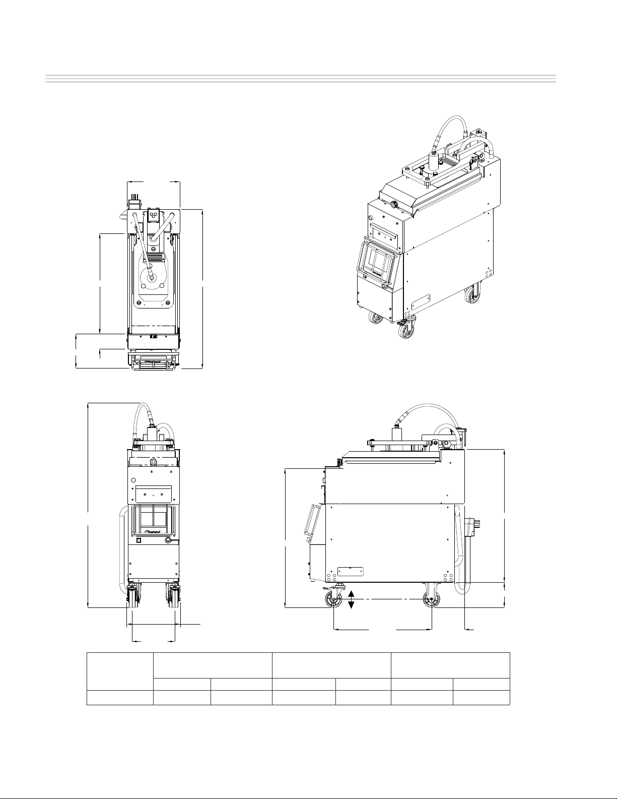
DIMENSION SPECIFICATION
Dimensions: Broiler
12.5 [318]
23.8 [606]
3.6 [91]
8.2 [207]
49 [1245]
APPROXIMATE
37.8 [960]
COOKING SURFACE
31.6 [801]
33.0 [839]
Page 6
6.0 [152]
±
0.5[12.7] FOR LEVEL
ADJUSTMENT(FRONT CASTERS ONLY)
23.3 [591] 7.8 [198]
WIDTH DEPTH
MODEL
10.2 [259]
12.7 [323]
HEIGHT
*
Inches mm Inches mm Inches mm
CXBE12-1
49 1245 12.5 318 37.8 960
* Height shown to top of the exible conduit and therefore indicated as approximate.
Part #4600670 - 2/15

GARLAND ELECTRIC CLAMSHELL BROILER GRILL, CXBE12-1 MODEL INSTALLATION OPERATION MANUAL
CLAMSHELL BROILER SPECIFICATION
Shipping Dimensions and Weight
SHIPPING DIMENSIONS
MODEL
Length Width Height *
43 1/2”
(1105mm)
CXBE12-1
Length Width Height
37 13/16”
(960mm)
* 44” (118mm) without exhaust fan
inches (mm)
27 3/8”
(695mm)
UNCRATED DIMENSIONS
inches (mm)
(1260mm)
12 1/2”
(960mm)
(1245mm)
49 5/8”
49”
Shipping Weight
545 lbs/247 Kg
Unit Weight
480 lbs/218 Kg
Electrical Input Speci cations
ELECTRICAL REQUIREMENTS**
MODEL OPTIONS
Voltage (V) Total kW
Frequency
(Hz)
Unbalance 3 phase Amps
per line
L1 L2 L3
with fan 208 / 3phase 16.05 60 43.4 43.4 47.0
CXBE12-1
without fan 208 / 3phase 16.00 60 43.2 43.2 47.0
A 5-foot (1.5m) long power supply cord with an integral (NEMA 15-50) plug is provided with each model.
Note: Wiring diagram is supplied with each unit.
Part #4600670 - 2/15
Page 7

INSTALLATION OPERATION MANUAL GARLAND ELECTRIC CLAMSHELL BROILER, CXBE12-1 MODEL
INTRODUCTION
GARLAND RECOMMENDS THAT INSTALLATION, MAINTENANCE AND REPAIRS BE DONE BY AN
AUTHORIZED SERVICE AGENCY, OTHERWISE THE WARRANTY WILL BE DEEMED NULL AND
VOID. FOR A LIST OF AUTHORIZED SERVICE AGENTS, REFER TO THE GARLAND WEB SITE AT
http://www.garland-group.com.
This appliance should be given regular care and maintenance to operate at peak performance and
maximum energy e ciency. It is recommended that the unit be inspected every 6 months by a
certi ed service technician for proper operation and performance. Remember “regular maintenance
ensures peak performance.”
Every broiler is inspected and tested at the factory prior to shipment.
Packing
The product is shipped in a substantial crate with
the broiler in vertical position. Casters are factory
installed on the broiler. Garland places the unit/
accessories in the crate in a neat and organized
manner and in such a way as to eliminate
damage from movement, rubbing etc.
Check crate for any visible damage sustained
during transit.
It is recommended to remove crate when the
clamshell broiler is inside the kitchen.
Unpacking
CAUTION
Heavy load
Use of lifting aids
and proper lifting
technique required
Carefully remove unit from crate and thoroughly
inspect it for any visible or concealed damage.
Report any damage immediately to your carrier
to le the appropriate freight claims. For more
information, see page 4. Push or pull broiler must
be taken care to see that the broiler does not tip
over.
Do not remove any permanently a xed labels,
warnings or data plates from the appliance as
this may invalidate the Garland warranty.
Temporary Storage
Garland provides adequate protection under
normal conditions. The broiler may need
additional protection if it is stored near salt water,
a tropical area, or other unfavorable conditions.
You must contact Garland immediately if these
conditions occur.
Safety
It is essential that the instructions in this manual
be strictly followed for the safe and economical
operation of the equipment. Should it be
known or suspected that a fault exists with the
appliance, then it must not be used until the fault
is recti ed by a authorized or certi ed service
person.
This appliance provides a sleep mode which
ensures the unit avoids overheating when idle.
Page 8
Part #4600670 - 2/15
GARLAND ELECTRIC CLAMSHELL BROILER GRILL, CXBE12-1 MODEL INSTALLATION OPERATION MANUAL
INSTALLATION
THIS PRODUCT IS NOT AUTHORIZED FOR HOME OR RESIDENTIAL USE. GARLAND WILL NOT PROVIDE
SERVICE, WARRANTY, MAINTENANCE, OR SUPPORT OF ANY KIND OTHER THAN IN COMMERCIAL
APPLICATIONS.
General
In the United States the installation must comply
with the latest edition of the National Electrical
Code ANSI/NFPA 70 – latest edition and/or local
Codes to assure safe and e cient operation.
In other countries installation must be carried out
by a factory authorized service representative
according to the relevant regulations, codes of
practice and the related requirements of the
country of destination.
Adequate clearance must be provided for
servicing and proper operation.
If you have any questions regarding the
installation of this unit, contact the Manitowoc
KitchenCare at (855)-586-1542 or Garland
Regional Service Managers.
Rating Plate
Two (2) rating plates will be installed on each
unit, and they can be found:
a. Inside the front panel under the electronic
touch control.
b. The lower edge of the right exterior body side
near the front of the unit.
If service or replacement
parts are needed, refer to
the model number
(including pre x & su x
letters/numbers) and serial
number on the rating plate
when in contact with the
factory or authorized
a
b
service agency. These
numbers ensure proper
unit identi cation, faster and more accurate
service.
Positioning and Setup
CAUTION
Heavy load
Use of lifting aids
and proper lifting
technique required
The unit is very heavy (500 Lbs) so some form of
mechanical assistance is recommended to lift
and position the broiler.
The unit is designed to be placed on a smooth
and level oor built to withstand the weight
of the fully laden appliance. To comply with
NSF Sanitation Standards the unit must stand
on casters for ease of mobility during cleaning
procedures.
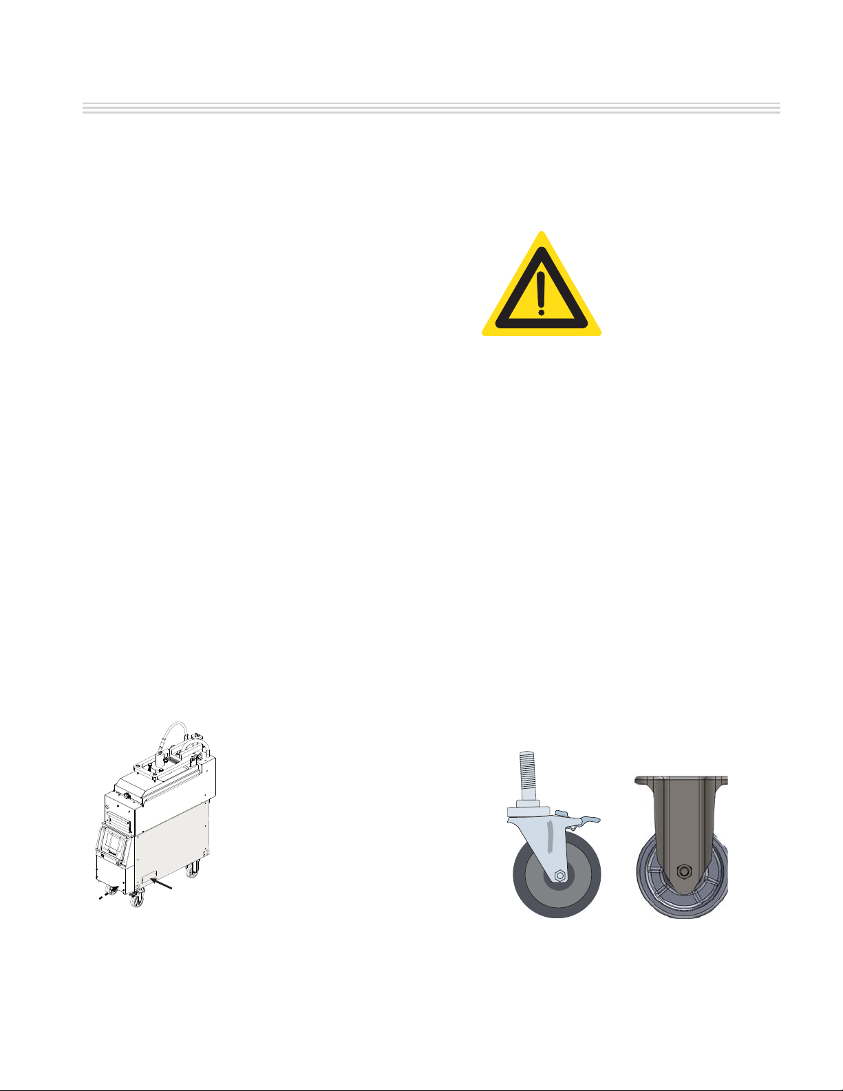
Appliances Equipped with Casters
All broilers are shipped with casters installed
in place, however some adjustment may be
required to level the unit. The front casters are
adjustable swivel casters with brakes. The rear
casters are xed. Garland recommends installing
restraining chains/cables from the oor/wall to
the rear of the unit. These restraints limit the
mobility of the appliance.
FRONT CASTER WITH BRAKE REAR CASTER WITHOUT BRAKE
Part #4600670 - 2/15
Page 9
INSTALLATION OPERATION MANUAL GARLAND ELECTRIC CLAMSHELL BROILER, CXBE12-1 MODEL
INSTALLATION, continuation
Air Supply and Ventilation
VENTILATION REQUIREMENTS MAY BE SUBJECT
TO LOCAL BUILDING AND FIRE CODES. CONSULT
LOCAL AUTHORITIES HAVING JURISDICTION.
This broiler appliance must be vented properly
to operate correctly and safely. Due to the
extremely high temperature a re safety system
should be installed. In addition, frequent
cleaning of the vent hood and the appliance
greatly reduces any re risk.
For any commercial cooking appliance, means
must be provided to exhaust combustion
waste products, steam, etc. to the outside of
the building. Proper ventilation is essential for
optimum performance.
Air movement should be checked during
installation. There must be adequate air
intake into the building to compensate for
the amount of air removed by the ventilation
system. Without a proper balance, abnormal
atmospheric pressure will occur, a ecting burner
and appliance performance. If air movement is a
concern, adjustments should be made to correct
the problem by Factory authorized service
technician.
HAVING DIFFICULTY OPENING DOORS THAT
EXIT THE BUILDING IS AN INDICATION THAT
THE BUILDING HAS A PROBLEM WITH AIR
MOVEMENT.
Do not use fans to blow air directly at the
appliance. This can create air cross-currents
and/or excessive drafts that interfere with the
operation of the unit.
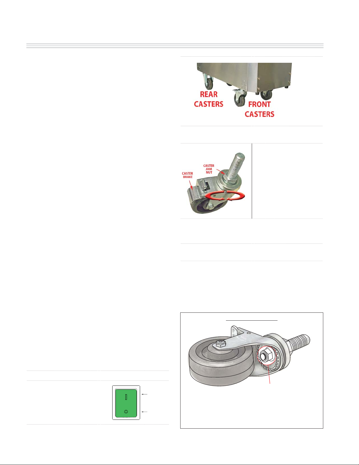
2. Rear Casters are xed - DO NOT ATTEMPT TO
ADJUST THEM.
3. Adjust the two (2)
front casters only.
4. Lock the caster using
the caster brake (Note:
applying the caster
brake system will lock
the wheel and the swivel
of the caster assembly).
5. Carefully raise front of unit slightly so that front
wheels are o the ground and no longer bearing
unit weight.
6. Loosen caster jam nut by turning it clockwise
with a wrench.
7. Adjust the caster assembly by turning the caster
(brake on) clockwise to increase the height or
counterclockwise to decrease the height.
8. After the broiler is completely level, tighten
caster jam nut to secure the caster assembly.
IMPORTANT NOTE
Front Caster Adjustment
1. Turn the clamshell
broiler Green Power Main
Switch OFF. ( “0” position)
Page 10
ON
OFF
DO NOT TOUCH CASTER NUT
On the caster assembly shown above there is a
nut used to assemble the swivel system - do not
use wrench on this nut. This nut is intended for the
caster swiveling system only.
Part #4600670 - 2/15

GARLAND ELECTRIC CLAMSHELL BROILER GRILL, CXBE12-1 MODEL INSTALLATION OPERATION MANUAL
ELECTRICAL CONNECTION
HIGH
DISCONNECT THE POWER SUPPLY BEFORE SERVICING.
VOLTAGE
IMPORTANT: The appliance must be electrically
grounded in accordance with local codes, or in
the absence of local codes, with the National
Electrical Code ANSI/NFPA70, or the Canadian
Electrical Code CSA C22.2, as applicable.
Electrical Grounding Instructions
The appliance is equipped with a standard Nema
15-50 plug with appropriate strain relief for your
protection against shock hazard and should be
plugged directly into a properly grounded three
prong receptacle. Do not cut or remove the
grounding prong from this plug.
Important Electrical Precautions
Never touch anything that is powered by
electricity when your hands are wet.
It is recommended to allow enough slack on the
electrical cord to allow the appliance to be pulled
out for proper regular cleaning and maintenance.
DO NOT USE AN EXTENSION CORD TO CONNECT
THIS UNIT TO A POWER SUPPLY.
DO NOT USE THIS APPLIANCE IF THE POWER
CORD IS DAMAGED.
DO NOT ATEMPT TO REPAIR A DAMAGED POWER
CORD.
DO NOT EXPOSE THE POWER CORD TO HEAT OR
SHARP EDGES.
DO NOT OPERATE BROILER IF THE CORD HAS
BEEN PINCHED OR HAS BEEN DAMAGED AS A
RESULT OF RUBBING ON SHARP EDGES.
Part #4600670 - 2/15
Page 11
INSTALLATION OPERATION MANUAL GARLAND ELECTRIC CLAMSHELL BROILER, CXBE12-1 MODEL
CLAMSHELL BROILER START UP
IMPORTANT NOTE:
Prior to installation, check the electrical supply to ensure input voltage and phase match the
equipment - voltage rating and phase. Many local codes exist and it is the responsibility of the
owner/installer to comply with these codes.
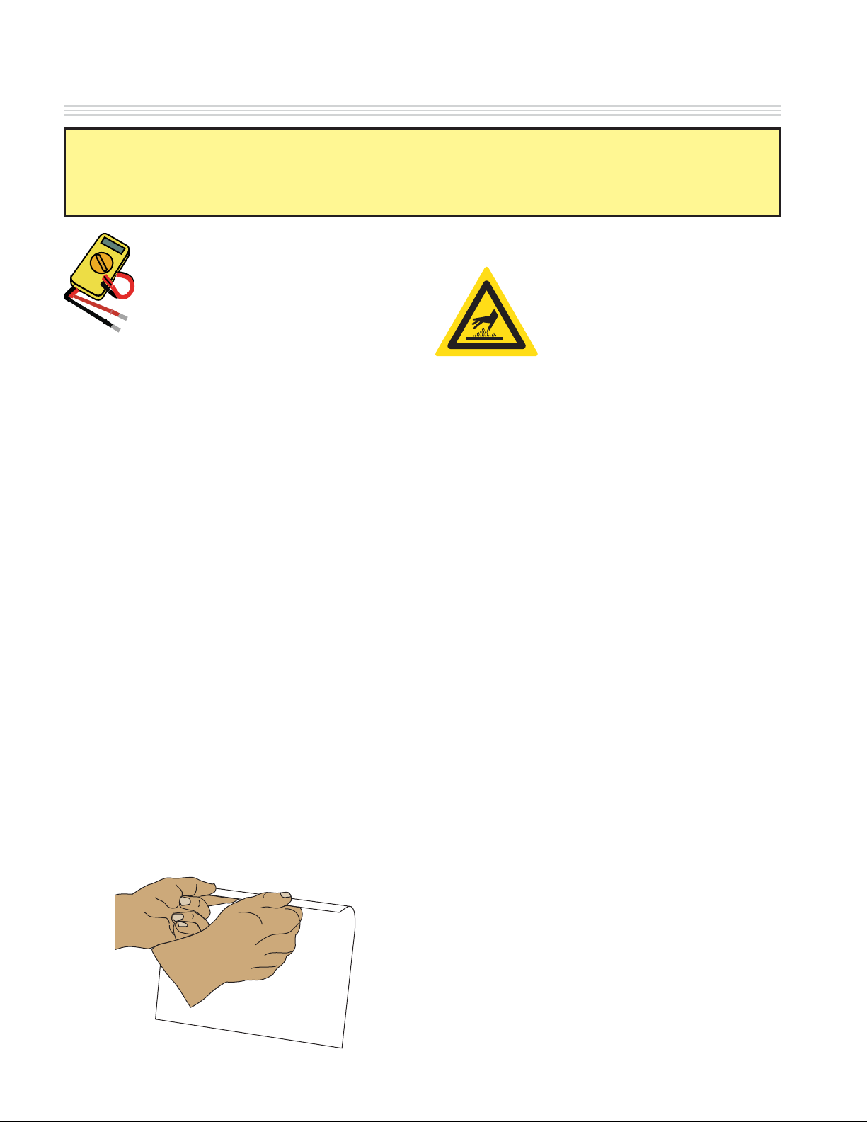
Temperature Verification
Certied
Installer
Ensure power supply is connected to the
appliance.
Remove all factory applied protective material
by washing with hot water, mild detergent, or a
soap solution.
The upper and lower clamshell broiler cooking
surfaces must be cleaned.
The broiler is designed and rated for operating
conditions where the temperature is above 32F.
HOT SURFACE
Grill Temperatures
Will Cause Severe
Burns
NOTE: Each clamshell broiler has been factory
tested and adjusted prior to shipment. It may
be necessary to further adjust the unit as part
of a proper installation. Such adjustments are
the responsibility of the installer. Adjustments
are not considered to be defects in material and
workmanship and are not covered under the
original equipment warranty.
REMOVE STAINLESS STEEL PLASTIC FILM COVER
Removing this lm is one of the things that must
be done once the broiler is in place. The lm
covers both internal and external components
(e.g. Side panels, crumb tray, grease shield) and
must be removed before turning the broiler on.
1. Using a plastic scraper wedge the lm away
from the stainless steel.
2. Grasp and pull the lm very gently away from
the stainless steel.
1. The upper and lower clamshell broiler should
be at operating temperatures to perform this
calibration veri cation (approximately 30
minutes).
2. Place temperature probe over the
thermocouple A as per gure #1 (under:
thermocouple locations diagram). Allow
about 10 seconds for the pyrometer to
respond and stabilize temperature.
3. Temperature delta between pyrometer and
0
controller must be +/- 20
F. If temperature
delta between pyrometer and controller
0
is greater than +/- 20
F, call Manitowoc
KitchenCare at 1- 855-586-1542.
4. Repeat for thermocouples located at
positions B, C, & D.
Page 12
PEEL OFF PLASTIC FILM
Part #4600670 - 2/15

GARLAND ELECTRIC CLAMSHELL BROILER GRILL, CXBE12-1 MODEL INSTALLATION OPERATION MANUAL
”
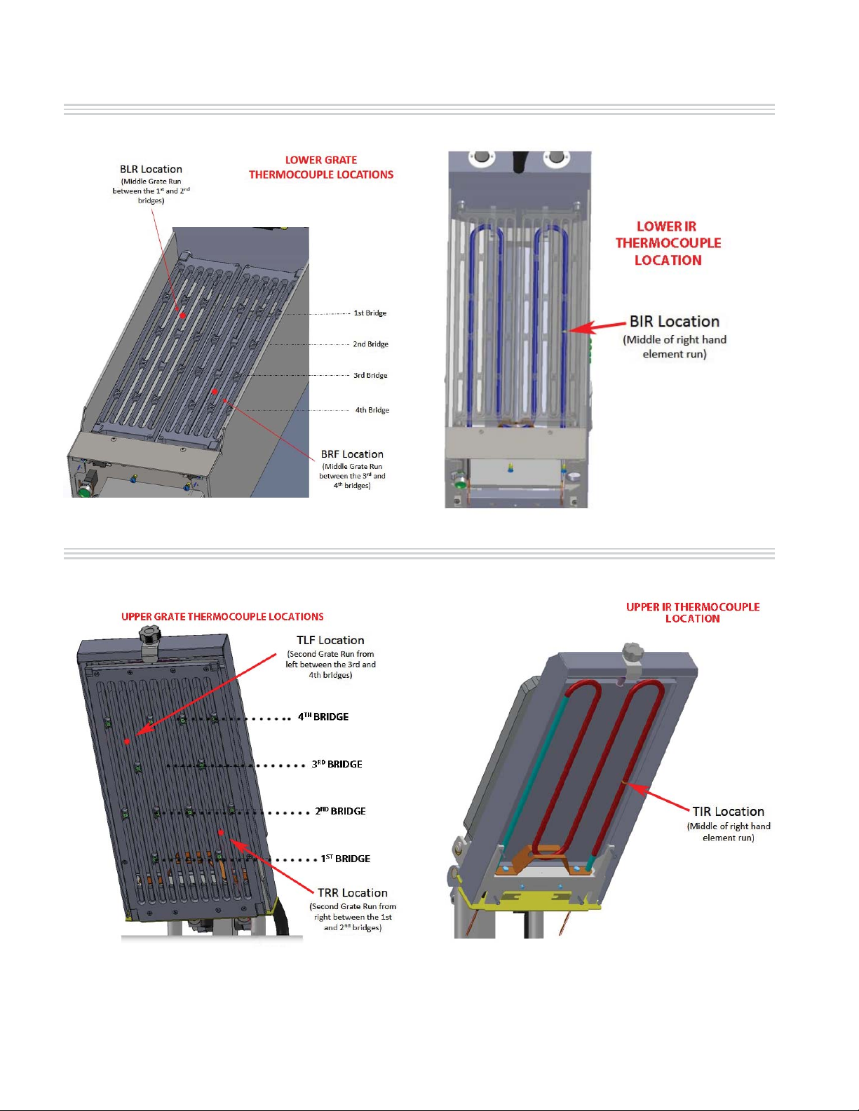
THERMOCOUPLE LOCATIONS DIAGRAM
HOT SURFACE
THERMOCOUPLE LOCATION
Grill Temperatures
Will Cause Severe
Burns
2.72”
14.92”
A
B
7.68”
COOKING AREA
-BOTTOM-
2.35”
2.72”
14.73”
RL
GRILL FRONT
C
2.35
D
7.23
RL
COOKING AREA
-TOP-
Part #4600670 - 2/15
A = Bottom Left Rear
B = Bottom Right Front
Figure #1
C = Top Right Rear
D = Top Left Front
Page 13
INSTALLATION OPERATION MANUAL GARLAND ELECTRIC CLAMSHELL BROILER, CXBE12-1 MODEL
LOWER THERMOCOUPLE LOCATIONS
UPPER THERMOCOUPLE LOCATIONS
Page 14
Part #4600670 - 2/15
 Loading...