

Garland 4523368 Instructions Manual
Part #
Description
Quantity
1415703
Baso Safety Valve
1
4522554
7/16” x 10” Flex Tube
2
4522558
Pre-bent 3/16” Tubing
1
076050-89
3/16” Union
1
M231
1/4IN X 3/16IN CC COMP Nut
2
M126
1/4IN TO 3/16IN SLEEVE - Ferrule
2
1095499
7/16cc – 3/8 NPT Straight Connector
2
4522557
Valve Bracket
1
F60
#10 x 5/8 Sheet Metal Screw
4
M123
7/16IN C.C. COMPRESSION - Nut (for Flex Tube end)
2
M122
7/16IN C.C. BALL SLEEVE - Ferrule (for Flex Tube end)
2
F312
LOCK NUT-10-24 K-LOCK - Nut (for Baso Valve)
1
F587
BOLT # 10-24 x 2-1/4 SL - Bolt (for Baso Valve)
1
4522556
Redesigned Kick Panel
1
4522201
Welded Bracket Oven Burner
1
F32
#10-24 x ½ Pan HD Type F Screw (For Pilot Bracket)
1
070239-10
RC Pilot Natural Gas
1
078239-11
RC Pilot Propane
1
M124
¼” Tubing Ferrule
1
M125
¼” Comp. Nut
1
1415000
Robertshaw Thermocouple
1
4521446
¼” x 12” Flex Tube
1
4523367
MANUAL-HIGH HEAT KIT-RC
1
G7227-1
Lighting Instructions
1
M121
Rivet
2
H280-series Valve Overheat / Relocation Kit Instructions: RC Ovens
Instructions for Applying Kit #4523368
This kit is for a convection RC, 36” oven only. For a Standard 36” oven, use Kit #4522559
Installation Prerequisites:
RC Oven, Piezoelectric Ignition
U-Burner with no welded bracket
Tools Needed:
Wrenches
Small Hacksaw (for extension installation if required)
Screwdrivers (Robertson, Flat), long and short
Riveter
Electrical Tape
Parts:
03/09/09 P/N 4523367 Page 1
Instructions:
1) Remove Kick Plate
Unscrew and set aside
This kick plate will not be reinstalled. A replacement is provided in the kit.
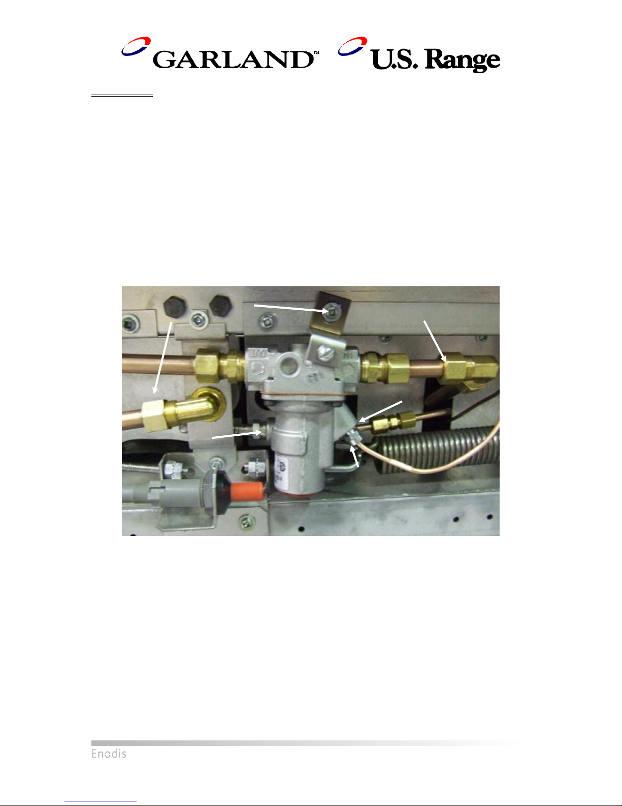
2) Remove Safety Valve
The following steps will apply for a Baso Valve:
1) Unscrew 11/16” compression nut on oven orifice fitting.
2) Unscrew 11/16” compression nut on 11/16” elbow on Valve Main Burner Gas Inlet.
Elbow itself should still be connected to Main Gas Inlet but detached from valve.
3) Unscrew 7/16” compression nut on Pilot Gas Inlet.
4) Unscrew 7/16” compression nut on Pilot Gas Outlet.
5) Unscrew 3/8” thermocouple nut.
6) Unscrew #10 sheet metal screw holding valve bracket onto lower front frame.
7) Remove valve.
03/09/09 P/N 4523367 Page 2
Baso Safety Valve: Prior to removal
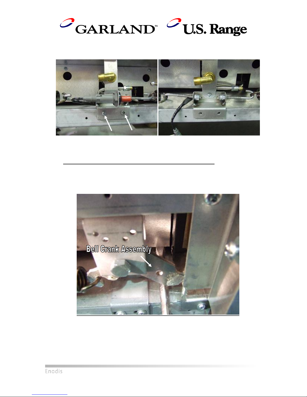
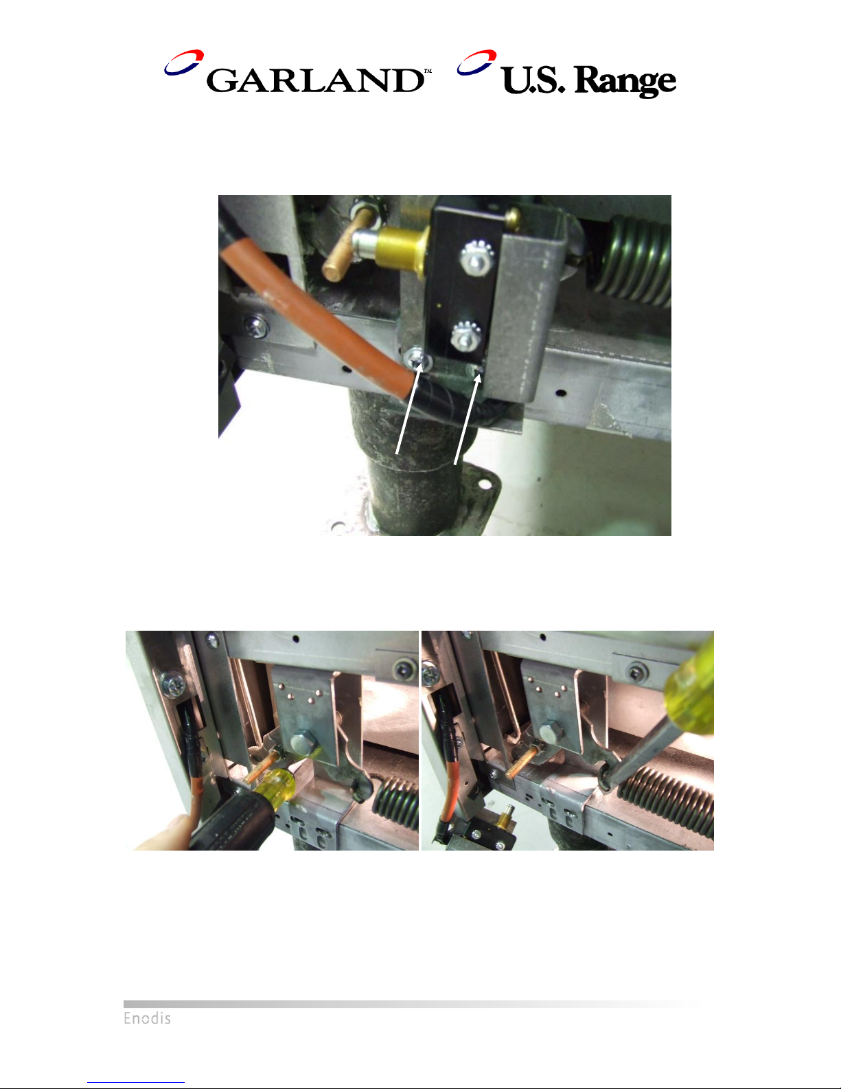
3) Unscrew Igniter Bracket
Unscrew the two screws holding down the igniter bracket to the orifice bracket.
Left: Before removal, location of screws shown by arrows
Right: After removal
4) Remove Door Springs
Once the springs are removed, the oven door will be free to fall. Use a strong tape to
keep the oven door closed for safety purposes.
For the door hinge with no microswitch:
Insert a long screwdriver underneath the bell crank assembly such that the tip
extends behind the air shield. See the following pictures for details.
Insertion of screwdriver underneath bell crank assembly and air shield
03/09/09 P/N 4523367 Page 3
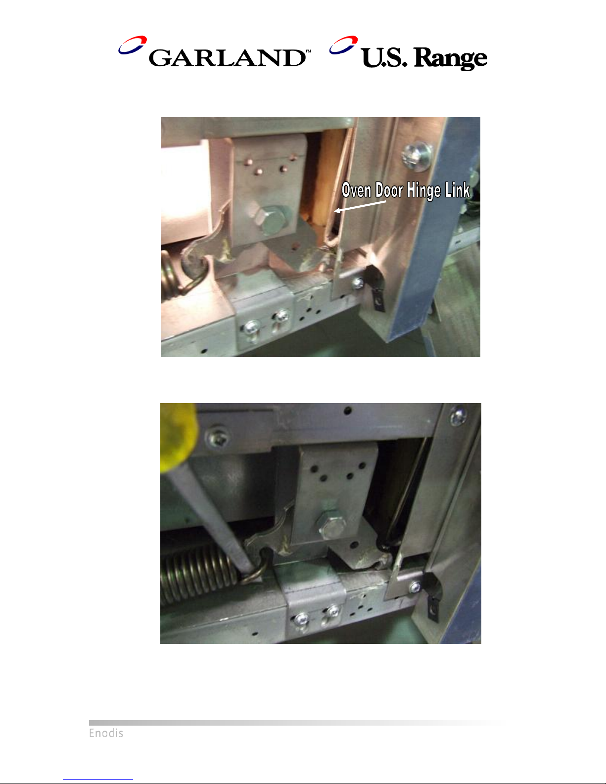
Pry upward with the screwdriver. While holding this position, unhook the oven door
hinge link.
Unhooked oven door hinge link
Use flat head screwdriver to pry spring from bell crank assembly. Remove spring.
Prying spring from bell crank assembly
03/09/09 P/N 4523367 Page 4
For the door hinge with a microswitch:
Unscrew the microswitch bracket from the oven frame. It is important that the
microswitch be removed prior to removing the spring to prevent damage to the
microswitch when the springs are reinstalled later.
Microswitch bracket held to oven frame by two screws indicated by the arrows
Follow the same steps as before, using the screwdriver to pry the bell crank
assembly upwards to unhook the oven door hinge link, then pry the spring loose from
the bell crank assembly.
03/09/09 P/N 4523367 Page 5
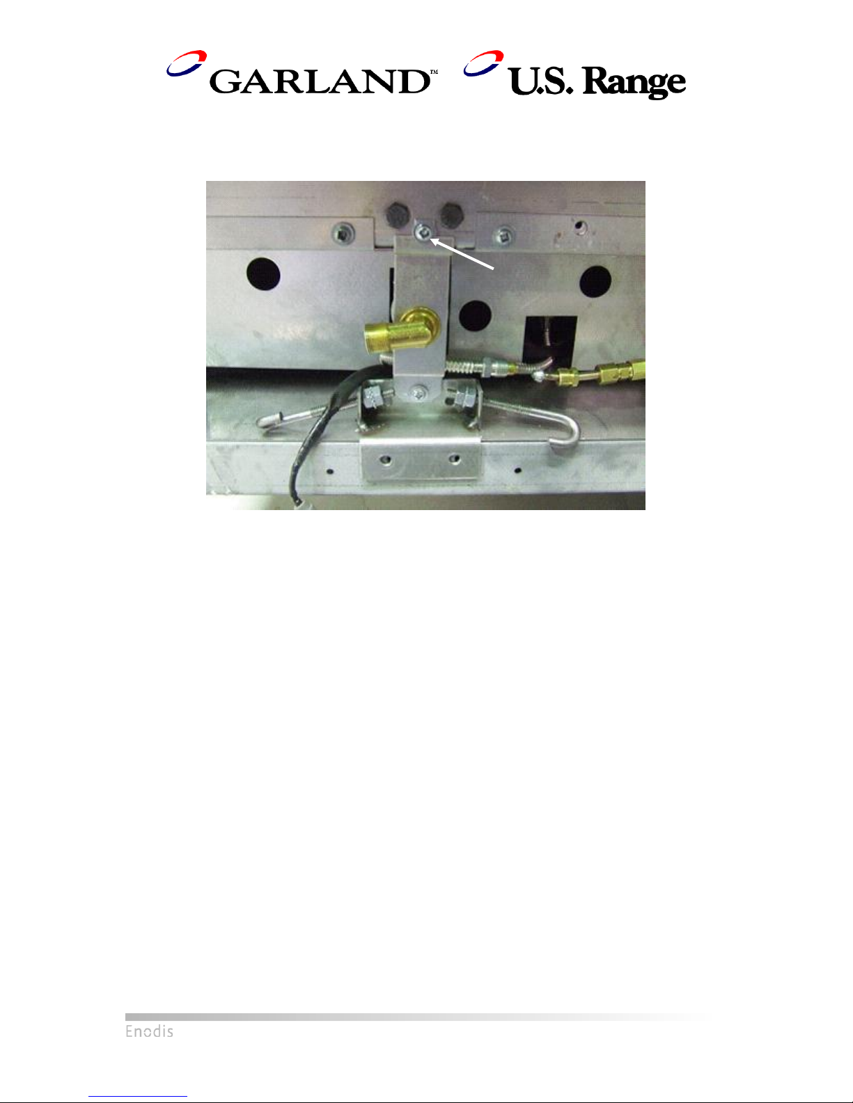
5) Remove Orifice Bracket
After removing the igniter bracket, the orifice bracket will be held in place by a single
screw directly above the orifice.
Note that with the removal of the igniter bracket, the orifice bracket is held down by a single screw
as shown by the arrow
03/09/09 P/N 4523367 Page 6

Screw this nut
onto the fitting
to secure the
fitting onto the
tube
3/16” Ferrule
6) Install Extension Fitting (if applicable)
If pilot gas tube going into the valve already has an extension piece (short piece of
tubing plus 3/16” brass fitting), unscrew the shorter piece of tubing and proceed to
Step 13. Otherwise, follow these steps to install the proper fitting.
This step must be performed if a TS-11 valve was just removed.
If a Baso valve was uninstalled, cut off 2.5” of the free end of the incoming pilot gas tube
to remove the original ferrule and nut and a section of the tubing. If a TS-11 valve was
uninstalled, cut off just enough tubing to remove the ferrule.
Refer to the Assembly Drawing included in this manual:
i) Unscrew one end of the 3/16” fitting (Part 4, Assembly Drawing) to release the
nut and ferrule. Slide the nut and the ferrule onto the free end of the incoming
pilot gas tube.
ii) Insert the remaining portion of the fitting onto the end of the pilot gas tube. Screw
on the nut to firmly attach the fitting to the tube. See pictures below for details.
iii) Ensure all connections are leak-proof. Do not over-tighten.
Left: Measure 2.5” from tip of pilot tube and cut
Right: Pilot tube after cutting
Extension fitting installed, with nut released to show location of ferrule
03/09/09 P/N 4523367 Page 7
 Loading...