

Page 1
GARDENA
®
D
GBFNLS
I
E
P
DK
F 5000 S Art. 7932
F 8000 S Art. 7939
D Betriebsanleitung
UVC-Teichfilter-Set
GB Operating Instructions
UVC Pond Filter Set
F Mode d’emploi
Kit filtre de bassin UVC
NL Instructies voor gebruik
UVC-vijverfilterset
S Bruksanvisning
UVC-dammfiltersats
I Istruzioni per l’uso
Set filtro per laghetti UVC
E Manual de instrucciones
Juego de filtros para estanque UVC
P Instruções de manejo
Conjunto de filtros para lagos UVC
DK Brugsanvisning
UVC-bassinfiltersæt
Page 2
11
GB
Purpose
Please note
Contents
2. Safety Instructions
V Comply with the safety instructions on the GARDENA UVC Pond Filter Set.
WARNING!
V Read the operating
instructions before
using the equipment
for the first time!
DANGER !
V Ultraviolet radiation.
Protect eyes from flash.
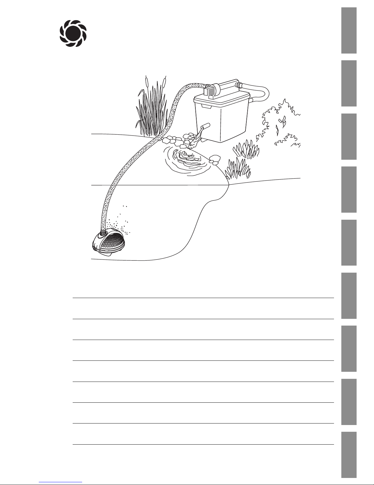
GARDENA UVC Pond Filter Set F 5000 S / F 8000 S
Welcome to GARDENA aquamotion...
Translation of the original instructions from German.
Please read these operating instructions carefully and follow the
instructions. Use these instructions to get to know the UVC Pond
Filter Set, using it correctly and the safety instructions.
For safety reasons, children and young people under 16 years
of age and people who are not acquainted with these Operating
Instructions may not use this UVC Pond Filter Set.
v Please keep these operating instructions in a safe place.
1. Range of Uses for Your GARDENA UVC Pond Filter Set . . . . 11
2. Safety Instructions
. . . . . . . . . . . . . . . . . . . . . . . . . . . . . . . . . . . . . . . . . . . . 11
3. Function
. . . . . . . . . . . . . . . . . . . . . . . . . . . . . . . . . . . . . . . . . . . . . . . . . . . . . . 13
4. Assembly
. . . . . . . . . . . . . . . . . . . . . . . . . . . . . . . . . . . . . . . . . . . . . . . . . . . . . 13
5. Initial Operation
. . . . . . . . . . . . . . . . . . . . . . . . . . . . . . . . . . . . . . . . . . . . . . 14
6. Maintenance
. . . . . . . . . . . . . . . . . . . . . . . . . . . . . . . . . . . . . . . . . . . . . . . . . . 15
7. Trouble-Shooting
. . . . . . . . . . . . . . . . . . . . . . . . . . . . . . . . . . . . . . . . . . . . . 16
8. Putting out of Operation
. . . . . . . . . . . . . . . . . . . . . . . . . . . . . . . . . . . . . . 17
9. Technical Data
. . . . . . . . . . . . . . . . . . . . . . . . . . . . . . . . . . . . . . . . . . . . . . . . 18
10. Accessories
. . . . . . . . . . . . . . . . . . . . . . . . . . . . . . . . . . . . . . . . . . . . . . . . . . . 18
11. Service / Warranty
. . . . . . . . . . . . . . . . . . . . . . . . . . . . . . . . . . . . . . . . . . . . 18
1. Range of Uses for Your GARDENA UVC Pond Filter Set
The GARDENA UVC Pond Filter Set is intended for private use
in domestic gardens and allotments and should only be used out
of doors for cleaning garden ponds with and without fish.
F 5000 S: F 8000 S:
for ponds with a volume of for ponds with a volume of
up to 5000 l without fish / up to 8000 l without fish /
2500 l with fish 4000 l with fish
The GARDENA UVC Pond Filter Set cleans the pond water biologically and mechanically and reduces the growth of algae. Algae
is bound together and pathogens (particularly in fish ponds) are
destroyed.
The GARDENA UVC Pond Filter Set is not suitable for
industrial use or in combination with chemicals, food,
easily combustible and explosive substances.
Page 3

12
GB
This radiation is harmful to eyes and skin.
➔ Never operate the UV unit when the
housing has been removed.
Electrical safety:
vv
Inspect the equipment before use to
ensure that the pump and the UVC unit,
especially the power cable and plug, are
undamaged.
Do not use a damaged UVC unit or pump.
Do not use the light if the connection lead,
glass tube or the housing of the UVC unit
appear to be defective.
If the pump or UVC unit is damaged, please
have them checked by our GARDENA Service
Centre or an authorised electrician.
The UVC-unit and the pump must be operated via a residual-current device (FI-switch)
with a nominal fault current ≤ 30 mA (DIN
VDE 0100-702 and 0100-738).
v Please ask your electrician for his advice.
Mains power cables should not have a smaller
cross-section than a rubber sheathed cable of
the designation H05 RNF.
Extension cables must meet the requirements
of DIN VDE 0620.
The information on the model plate of the
UVC unit must match the power supply.
The connection cable of the UVC-unit and the
pump cannot be replaced.
If the cable is damaged the UV unit must be
scrapped.
Do not use extension leads, connection leads
or adapters without a protective contact.
The fountain pump must not be operated
when there are people in the water.
Swimming pools and garden ponds should
be designed according to international and
national design regulations.
v Please ask your electrician for his advice.
Never carry the UVC-unit and the pump by the
cable. Do not pull on the cable to unplug the
plug from the socket.
Please protect the cable from heat, oil and
sharp edges. Make sure that connection
points remain dry.
Always unplug the equipment when dismantling the set, when it is not in use and
before maintenance.
v Always disconnect the UVC unit and the
pump from the mains before undertaking
any work on them.
For Austria
In Austria power cables should correspond to
ÖVE-EM 42, T2 (2000) /1979 § 22 according
to § 2022.1. According to this standard units
used in swimming pools and ponds should
only be operated via an isolating transformer.
v Please contact your electrician.
For Switzerland
In Switzerland mobile appliances which are
used outdoors, must be connected via a
residual-current device.
Notes:
Never operate the UVC unit without water
throughput.
Never let the pump run dry; running dry
generates heat and will damage the pump.
Sand and other abrasive substances in the
liquid cause increased wear and reduce the
output of the pump.
The temperature of the liquid used must not
be below 4 °C or above 35°C.
Safety switch:
If the UVC light overheats, it is switched off
by the built-in thermal protection switch. The
UVC light switches itself on again automatically when it has cooled down sufficiently.
Due to the integrated safety switch the lamp
only comes on when the UVC unit is properly
installed.
Positioning the filter:
v
Stand or bury the filter housing in a stable
position at least 2 m away next to the
garden pond.
The filter must be positioned higher than the
surface of the pond.
Bacterial Activity:
Extensive bacterial activity arises
from + 10 °C onwards.
The filter system is a biological system and
therefore, when newly installed, needs a few
weeks until it is fully effective.
If possible, the filter should be in permanent
operation from spring to autumn and should
not dry out.
Page 4
13
GB
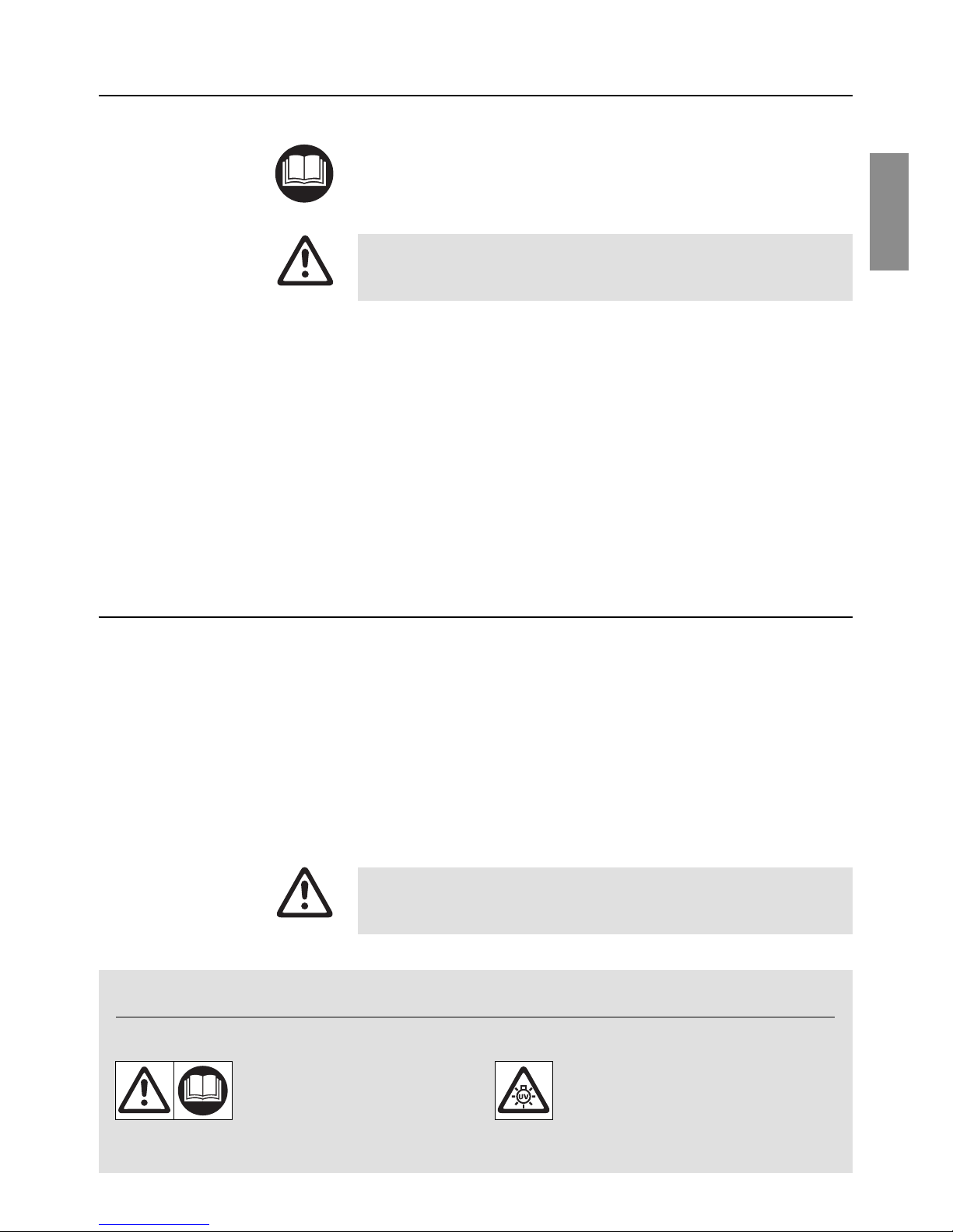
3. Function
!
Water intake
Universal connection for the pump supply hose in the pond.
"
UVC-radiation
The pond water, which has already undergone preliminary
treatment, is subjected to short wave UVC-light (ultraviolet rays).
During this process, the algal growth is reduced and germs which
cause disease in fish ponds are killed.
§
Mechanical filtering
Dirt in the pond water is retained mechanically by the large outer
surface of the foam components in the filter.
$
Biological treatment
The biological pond water treatment takes place in two different
areas of the filter:
• Blue filter sponge/bio-surface elements :
This promotes the growth of micro-organisms which guarantee
the conversion of ammonia into nitrate via nitrite (nitrification).
• Black filter sponge/ lava stone:
This supports the growth of anaerobic micro-organisms which
promote denitrication (reduction of nitrate to nitrogen).
%
Water outlet
Connection nipple (11/4” ) to enable the treated water to be
returned.
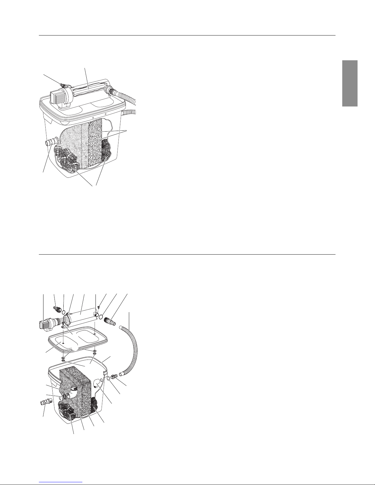
4. Assembly
1. Turn UVC unit head 1of the UVC unit 2anti-clockwise 1 and
remove carefully 2 (bayonet fitting). (see 7. Trouble-Shooting
“Changing the bulb”
).
2. Push the two bolts
3
into the guides on the UVC unit 2and
place on the filter cover 4.
3. From underneath, screw one washer
5
and one nut 6respec-
tively on to the bolts
3
and screw the UVC unit 2firmly on to
the filter cover 4.
4. Screw one universal connection nipple
0
with O-ring 9on the
UVC-intake 7und UVC-outlet 8respectively.
5. Insert water outlet (1 1/4”)
A
from outside into the drilled hole,
push the large sealConto the water outlet Afrom inside and
screw the large angled piece Bon the water outlet A(the
large angled piece
B
must point upwards).
6. Push small seal
E
on to the water intake (3/4” ) D, push it into
the drilled hole and screw the small angled piece Fon to the
water intake D(the seal Esits on the outside on the filter
housing Kand the angled piece Fmust point downwards).
7. Place coarse filter sponge (blue)
G
and fine filter sponge
(grey)
H
in the centre of the filter as illustrated.
8. Insert the lava stone
I
on the intake side and the flat bio-
elements Jon the outlet side.
9. Press filter cover
4
with UVC unit 2on to the filter housing K.
Assembling the UVC filter:
%
§
$
"
!
1 0 9 7
3
3
5
4
B
C
A
J
H
G
I
K
6
2 8 9 0
L
D
E
F
Page 5

14
GB
Return flow tip:
Start up UVC-pond filter:
10. Connect the UVC outlet 8to the water intake Dof the filter
with approx. 50 cm of the hose supplied L.
11. Insert UVC bulb and fit UVC unit (see 7. Trouble-Shooting
“Changing the bulb”
).
1. Cut the connecting hose
M
between pump and filter to size
accordingly.
2. Screw the adapter
P
(pre-mounted) and connecting nipple
O
on the pump.
3. Push the hose clamp
N
onto the connecting hose M.
4. Slide the connecting hose
M
onto the connecting nipple O.
5. Secure the connecting hose
M
with the hose clamp N.
5. Initial Operation
1. Stand or bury the filter housingKin a stable position at least
2 m away next to the garden pond.
The outlet may not be more than 1m above the surface of the
pond.
Set up the UVC-pond filter horizontally so that the filter cannot
overflow.
2. Using the remainder of the hose
M
, connect the pump Qto the
UVC intake 7.
3. Place the pumpQin a stable position within the garden pond
so that the pump
Q
are completely covered with water.
4. Plug the mains plug of the pump
Q
into a 230 V AC socket.
Warning: The pump will start immediately!
5. Plug the mains plug of the UVC unit
2
nto a 230 V AC socket.
We recommend that you lay the return flow in such a way that the
purified water is reintroduced indirectly e.g. via a short stream.
This enriches the purified water with additional oxygen.
Join the connecting hose
to the pump:
M
N
O
P
2
Q
7
M
K
Page 6

15
GB
6. Maintenance
DANGER ! Electric shock!
A
vv
Before undertaking maintenance, unplug the
UVC-unit and the pump from the mains!
Do not use any chemical cleaning agents so that the bacteria
are not killed.
1. Remove filter cover
4
with UVC-unit 2from filter housing
K
and pull off the hose L.
2. Remove filter sponge
G/ H
and clean under running water.
3. Rinse the lava stone
I
and the bio-surface elements Jgently
in clean water (do not clean under running water).
4. Empty filter housing
K
completely and clean under running
water.
5. Re-assemble the filter in reverse order (see 4. Assembly
“Assembling the UVC-filter“
).
6. Restart the filter (see 5. Using for the First Time
“Starting the
UVC pond filter“
).
1. Take pump out of the water.
2. Unscrew the connecting hose.
3. Unlock snap fastening
R
and open up the pump housing S.
4. Take pump
T
out of the pump housing S.
5. Clean pump housing
S
with a jet of water.
6. Re-assemble pump in reverse order.
1. Turn the top
1
of the UVC unit anticlockwise 1 and carefully
remove 2 (bayonet socket).
2. Clean the glass tube
U
(using liquid glass cleaner, for
example).
3. Fit the UVC unit again in reverse order.
When installing, make sure that the O-ring
V
is inserted
correctly in the top of the UVC unit 1.
Cleaning the filter:
2
4
J
H
G
I
K
L
Cleaning the pump housing
of the pump:
Cleaning the UVC unit:
T
R
S
U
V
1
Page 7

16
GB
7. Trouble-Shooting
DANGER ! Electric shock!
A
vv
Before undertaking Trouble-Shooting, unplug the
UVC-unit and the pump from the mains!
The UVC bulb should be replaced after approximately 8,000
operating hours since the UVC performance decreases dramatically after this time.
Only bulbs of the type TC-S (UV-C) may be used. (E. g. Radium,
Philips or Sylvania: The correct UVC-bulb can be ordered from
GARDENA Service as a spare part.
1. Turn the top
1
of the UVC unit anticlockwise 1 and carefully
remove 2 (bayonet socket).
2. Carefully unscrew the ring
W
.
3. Pull off the glass tube
U
(It may be relatively difficult to remove
the glass tube due to mineral deposits.)
4. Take out faulty bulb
X
and insert new bulb.
5. Reassemble the UVC unit in reverse order.
WARNING! Short-circuit!
A
vv
The ring Wmust be screwed on firmly again to
guarantee that the glass tube Uis sealed!
When installing, make sure that the O-ring
Y
fits properly on
the glass tube Uand that the O-ring Vis inserted correctly in
the top of the UVC unit 1.
Due to the integrated safety switch the lamp only comes on when
the UVC unit is properly installed.
1. Remove pump from pump housing (see 6. Mainenance
“
Cleaning the pump housing of the pump”
).
2. Turn pump cover
z
36
anti-clockwise and draw vertically out of
the motor housing
z
37
(bayonet fitting).
3. Draw rotor unit
z
38
out of motor housing
z
37
and clean.
4. Push cleaned rotor unit
z
38
back into the motor housing
z
37
.
5. Press pump cover
z
36
vertically on to the motor housing
z
37
and close by turning clockwise.
During this, ensure that the O-ring
z
39
is installed correctly.
6. Assemble pump in the pump housing.
Changing the bulb:
Cleaning the pump:
U
W
V
1
X
Y
z
36
z
37
z
39
z
38
Page 8

17
GB
Fault Possible Cause Remedy
The water is not clear Filter or delivery capacity of v Check whether UVC pond
the pump not suitable. filter set is sufficient for the
pond. (see 1. Area of Use
of Your GARDENA UVC
Pond Filter Set).
Too many fish and creatures v Add up the estimated
in the pond. length of the fish.
There should only be “80 cm
fish” per m3water in the pond.
The glass tube of the UVC unit v Clean UVC unit
is dirty. (see 6. Maintenance).
The flow is reduced The filter sponges are dirty. v Clean filter
(see 6.Maintenance).
Pump filter housing is dirty. v Clean pump filter housing.
Rotor unit is blocked. v Clean pump.
he UVC pilot light is not on Bulb defective. v Change bulb.
Electrical connections defective. v Check electrical
connections.
A
In the event of other faults please contact GARDENA Service.
Repairs should only be carried out by GARDENA service centres or dealers
authorised by GARDENA.
8. Putting out of Operation
1. Before frosts commence, remove the pump from the pond,
take the hose off the pump and empty the filter completely.
2. Clean filter, UVC unit and pump thoroughly and dry it
(see 6. Maintenance).
3. Store filter, UVC unit and pump in a frost-free place.
Store out of reach of children.
The product must not be added to normal household waste. It
must be disposed of in line with local environmental regulations.
v Important: Make sure that the unit is disposed of via your
municipal recycling collection centre.
Overwintering /
Storage:
Disposal:
(in accordance with
RL2002/ 96/EC)
Page 9

18
GB
9. Technical Data
F 5000 S (Art. 7932) F 8000 S (Art. 7939)
Rated power, UVC unit 7 W 11 W
Power cable, UVC unit 3 m H05 RN-F3G0,75 3 m H05 RN-F3G0,75
Bulb, UVC unit type 7 W TC-S (UV-C) type 11W TC-S (UV-C)
(e.g. Radium: Puritec (e.g. Radium: Puritec
NSE 7-270, Philips: TUV NSE 11-270, Philips: TUV
PL-S 7 W or Sylvania: PL-S 11 W or Sylvania:
G7 LYNX-S Germicidal) G11 LYNX-S Germicidal)
Rated power, pump 25 W 40 W
Power cable, pump 10 m H05 RN-F 3G0,75 10 m H05 RN-F 3G0,75
Max. delivery capacity, pump 1,500 l/ h 2,500 l/ h
Max. delivery head, pump 1.9 m 2.2 m
Max. operating pressure 0.19 bar 0.22
Mains voltage /
mains frequency 230 V / 50 Hz 230 V / 50 Hz
Max. immersion depth 2 m 2 m
Media temperature 4 °C – 35 °C 4 °C – 35 °C
10. Accessories
GARDENA
Ribbed pond hoses
11/4”
-hose (for use as drainage hose)
Art. 7832
11. Service / Warranty
GARDENA provides a 2 year warranty on this product and a
3 year warranty on the pump (from date of purchase).
This guarantee covers all serious defects of the unit that can be
proved to be material or manufacturing faults. Under warranty we
will either replace the unit or repair it free of charge if the following
conditions apply:
• The unit must have been handled properly and in keeping
with the requirements of the operating instructions.
• Neither the purchaser or a non-authorised third party have
attempted to repair the unit.
The wearing parts UVC bulb, filter materials and rotor unit are excluded from the warranty.
This manufacturer’s guarantee does not affect the user’s existing
warranty claims against the dealer/seller.
If you have any problems with your UVC-pond filter, please
contact our Customer Service or return the defective unit together with a short description of the problem directly to one of the
GARDENA Service Centres listed on the back of this leaflet.
Page 10

78
F 8000 S Art. 7939
Pumpen-Kennlinie
Performance characteristics
Courbes de performance
Prestatiegrafiek
Kapacitetskurva
Curva di rendimento
Curva característica
de la bomba
Características
de performance
Ydelses karakteristika
F 5000 S Art. 7932
Pumpen-Kennlinie
Performance characteristics
Courbes de performance
Prestatiegrafiek
Kapacitetskurva
Curva di rendimento
Curva característica
de la bomba
Características
de performance
Ydelses karakteristika
Page 11

79
D
Produkthaftung
Wir weisen ausdrücklich darauf hin, dass wir nach dem Produkthaftungsgesetz nicht für durch unsere Geräte hervorgerufene Schäden einzustehen haben, sofern diese durch unsachgemäße Reparatur verursacht
oder bei einem Teileaustausch nicht unsere Original GARDENA Teile oder
von uns freigegebene Teile verwendet werden und die Reparatur nicht
vom GARDENA Service oder dem autorisierten Fachmann durchgeführt
wird. Entsprechendes gilt für Ergänzungsteile und Zubehör.
G
Product Liability
We expressly point out that, in accordance with the product liability law,
we are not liable for any damage caused by our units if it is due to improper repair or if parts exchanged are not original GARDENA parts
or parts approved by us, and, if the repairs were not carried out by a
GARDENA Service Centre or an authorised specialist. The same applies
to spare parts and accessories.
F
Responsabilité
Nous vous signalons expressément que GARDENA n’est pas responsable des dommages causés par ses appareils, dans la mesure où ces
dommages seraient causés suite à une réparation non conforme, dans la
mesure où, lors d’un échange de pièces, les pièces d’origine GARDENA
n’auraient pas été utilisées, ou si la réparation n’a pas été effectuée par
le Service Après-Vente GARDENA ou l’un des Centres SAV agréés
GARDENA. Ceci est également valable pour tout ajout de pièces et d’accessoires autres que ceux préconisés par GARDENA.
N
Productaansprakelijkheid
Wij wijzen er nadrukkelijk op, dat wij op grond van de wet aansprakelijkheid voor producten niet aansprakelijk zijn voor schade ontstaan door onze
apparaten, indien deze door onvakkundige reparatie veroorzaakt zijn, of er
bij het uitwisselen van onderdelen geen gebruik gemaakt werd van onze
originele GARDENA onderdelen of door ons vrijgegeven onderdelen en de
reparatie niet door de GARDENA technische dienst of de bevoegde vakman uitgevoerd werd. Ditzelfde geldt voor extra-onderdelen en accessoires.
S
Produktansvar
Tillverkaren är inte ansvarig för skada som orsakats av produkten om
skadan beror på att produkten har reparerats felaktigt eller om, vid reparation eller utbyte, andra än Original GARDENA reservdelar har använts.
Samma sak gäller för kompletteringsdelar och tillbehör.
I
Responsabilità
Si rende espressamente noto che, conformemente alla legislazione sulla
del prodotto
responsabilità del prodotto, non si risponde di danni causati da nostri articoli se originati da riparazioni eseguite non correttamente o da sostituzioni
di parti effettuate con materiale non originale GARDENA o comunque da
noi non approvato e, in ogni caso, qualora l’intervento non venga eseguito
da un centro assistenza GARDENA o da personale specializzato autorizzato. Lo stesso vale per le parti complementari e gli accessori.
E
Responsabilidad
Advertimos que conforme a la ley de responsabilidad de productos no nos
de productos
responsabilizamos de daños causados por nuestros aparatos, siempre
y cuando dichos daños hayan sido originados por arreglos o reparaciones
indebidas, por recambios con piezas que no sean piezas originales
GARDENA o bien piezas autorizadas por nosotros, así como en aquellos
casos en que la reparación no haya sido efectuada por un Servicio Técnico GARDENA o por un técnico autorizado. Lo mismo es aplicable para
las piezas complementarias y accesorios.
P
Responsabilidade
Queremos salientar que segundo a lei da responsabilidade do fabricante,
sobre o produto
nós não nos responsabilizaremos por danos causados pelo nosso equipamento, quando estes ocorram em decorrência de reparações inadequadas
ou da substituição de peças por peças não originais da GARDENA, ou peças não autorizadas. A responsabilidade tornar-se-à nula também depois
de reparações realizadas por oficinas não autorizadas pela GARDENA.
Esta restrição valerá também para peças adicionais e acessórios.
K
Produktansvar
Vi gør udtrykkeligt opmærksom på at i henhold til produktansvarsloven
er vi ikke ansvarlige for skader forårsaget af vores udstyr, hvis det skyldes
uautoriserede reparationer eller hvis dele er skiftet ud og der ikke er anvendt originale GARDENA dele eller dele godkendt af os, eller hvis reparationerne ikke er udført af GARDENA-service eller en autoriseret fagmand.
Det samme gælder for ekstra udstyr og tilbehør.
Page 12

80
Bezeichnung des Gerätes: UVC-Teichfilter-Set
Description of the unit: UVC-Pond filter-Set
Désignation du matériel : Kit filtre de bassin UVC
Omschrijving van het apparaat: UVC-vijverfilterset
Produktbeskrivning: UVC-dammfiltersats
Descrizione del prodotto: Set filtro per laghetti UVC
Descripción de la mercancía: Juego de filtros para
estanque UVC
Descrição do aparelho: Conjunto de filtros para
lagos UVC
Beskrivelse af enhederne: UVC-bassinfiltersæt
Typ : Art.-Nr.:
Type : Art. No.:
Type : Référence :
Ty p :
F 5000 S Art. nr.: 7932
Typ : Art.nr. :
Modello: F 8000 S Art. : 7939
Tipo: Art. Nº:
Tipo: Art. Nº:
Type : Varenr. :
EU-Richtlinien:
EU directives:
Directives européennes :
EU-richtlijnen:
EU direktiv:
Direttive UE:
Normativa UE:
Directrizes da UE:
EU Retningslinier:
Nationale Normen:
Anbringungsjahr der CE-Kennzeichnung:
Year of CE marking :
Date d’apposition du marquage CE :
Installatiejaar van de CE-aanduiding:
CE-Märkningsår : 2005
Anno di rilascio della certificazione CE :
Colocación del distintivo CE:
Ano de marcação pela CE:
CE-Mærkningsår :
Peter Lameli
Ulm, den 01.12.2005 Technische Leitung
Ulm, 01.12.2005 Technical Dept. Manager
Fait à Ulm, le 01.12.2005 Direction technique
Ulm, 01.12.2005 Hoofd technische dienst
Ulm, 2005.12.01. Technical Director
Ulm, 01.12.2005 Direzione Tecnica
Ulm, 01.12.2005 Dirección Técnica
Ulm, 01.12.2005 Director Técnico
Ulm, 01.12.2005 Teknisk direktør
D
EU-Konformitätserklärung
MMaasscchhiinneennVVeerroorrddnnuunngg ((99.. GGSSGGVVOO)) // EEMMVVGG // NNiieeddeerrsspp.. RRLL
Der Unterzeichnete GARDENA Manufacturing GmbH, Hans-Lorenser-Str. 40,
D-89079 Ulm, bestätigt, dass die nachfolgend bezeichneten Geräte in der von
uns in Verkehr gebrachten Ausführung die Anforderungen der harmonisierten
EU-Richtlinien, EU-Sicherheitsstandards und produktspezifischen Standards
erfüllen. Bei einer nicht mit uns abgestimmten Änderung der Geräte verliert
diese Erklärung ihre Gültigkeit.
G
EU Certificate of Conformity
The undersigned GARDENA Manufacturing GmbH, Hans-Lorenser-Str. 40,
D-89079 Ulm, hereby certifies that, when leaving our factory, the units indicated
below are in accordance with the harmonised EU guidelines, EU standards
of safety and product specific standards. This certificate becomes void if the
units are modified without our approval.
F
Certificat de conformité aux directives européennes
Le constructeur, soussigné : GARDENA Manufacturing GmbH,
Hans-Lorenser-Str. 40, D-89079 Ulm, déclare qu’à la sortie de ses usines
le matériel neuf désigné ci-dessous était conforme aux prescriptions des
directives européennes énoncées ci-après et conforme aux règles de sécurité
et autres règles qui lui sont applicables dans le cadre de l’Union européenne.
Toute modification portée sur ce produit sans l’accord express de GARDENA
supprime la validité de ce certificat.
N
EU-overeenstemmingsverklaring
Ondergetekende GARDENA Manufacturing, Hans-Lorenser-Str. 40,
D-89079 Ulm, bevestigt, dat de volgende genoemde apparaten in de door ons
in de handel gebrachte uitvoering voldoen aan de eis van, en in overeenstemming zijn met de EU-richtlijnen, de EU-veiligheidsstandaard en de voor het
product specifieke standaard. Bij een niet met ons afgestemde verandering
aan de apparaten verliest deze verklaring haar geldigheid.
S
EU Tillverkarintyg
Undertecknad firma GARDENA Manufacturing GmbH, Hans-Lorenser-Str. 40,
D-89079 Ulm, intygar härmed att nedan nämnda produkter överensstämmer
med EU:s direktiv, EU:s säkerhetsstandard och produktspecifikation. Detta
intyg upphör att gälla om produkten ändras utan vårt tillstånd.
I
Dichiarazione di conformità alle norme UE
La sottoscritta GARDENA Manufacturing GmbH, Hans-Lorenser-Str. 40,
D-89079 Ulm, certifica che il prodotto qui di seguito indicato, nei modelli da noi
commercializzati, è conforme alle direttive armonizzate UE nonché agli standard di sicurezza e agli standard specifici di prodotto. Qualunque modifica
apportata al prodotto senza nostra specifica autorizzazione invalida la presente
dichiarazione.
E
Declaración de conformidad de la UE
El que subscribe GARDENA Manufacturing, Hans-Lorenser-Str. 40,
D-89079 Ulm, declara que la presente mercancía, objeto de la presente declaración, cumple con todas las normas de la UE, en lo que a normas técnicas, de homologación y de seguridad se refiere. En caso de realizar cualquier
modificación en la presente mercancía sin nuestra previa autorización, esta
declaración pierde su validez.
P
Certificado de conformidade da UE
Os abaixo mencionados GARDENA Manufacturing GmbH, Hans-LorenserStr. 40, D-89079 Ulm, por este meio certificam que ao sair da fábrica o
aparelho abaixo mencionado está de acordo com as directrizes harmonizadas
da UE, padrões de segurança e de produtos específicos. Este certificado ficará
nulo se a unidade for modificada sem a nossa aprovação.
K
EU Overensstemmelse certificat
Undertegnede GARDENA Manufacturing GmbH, Hans-Lorenser-Str. 40,
D-89079 Ulm bekræfter hermed, at enheder listet herunder, ved afsendelse
fra fabrikken, er i overensstemmelse med harmoniserede EU retningslinier,
EU sikkerhedsstandarder og produktspecifikationsstandarder. Dette certifikat
træder ud af kraft hvis enhederne er ændret uden vor godkendelse.
2006/95 / EC
2004/108/EC
98/37 / EC : 1998
2006/42 / EC : 2006
93/ 68 /EC
EN 60335-1
EN 60335-2 - 41
EN 60598-1
EN 60598-2-1
EN 55014-1
EN 55014-2
EN 55015
EN 61000-3-2
EN 61000-3-3
Page 13

84
Deutschland /Germany
GARDENA
Manufacturing GmbH
Service Center
Hans-Lorenser-Straße 40
D-89079 Ulm
Produktfragen:
(+49) 731 490- 123
Reparaturen:
(+49) 731 490- 290
service
@
gardena.com
Argentina
Argensem
®
S.A.
Calle Colonia Japonesa s/n
(1625) Loma Verde
Escobar, Buenos Aires
Phone: (+54) 34 88 49 40 40
info
@
argensem.com.ar
Australia
Nylex Consumer Products
50-70 Stanley Drive
Somerton, Victoria, 3062
Phone: (+61) 1800 658 276
spare.parts
@
nylex.com.au
Austria / Österreich
GARDENA
Österreich Ges.m.b.H.
Stettnerweg 11-15
2100 Korneuburg
Tel.: (+ 43) 22 62 7 45 45 36
kundendienst
@
gardena.at
Belgium
GARDENA Belgium NV/SA
Sterrebeekstraat 163
1930 Zaventem
Phone: (+32) 2 720 92 12
Mail: info
@
gardena.be
Brazil
Palash Comércio e
Importação Ltda.
Rua Américo Brasiliense,
2414 - Chácara Sto Antonio
São Paulo - SP - Brasil CEP 04715-005
Phone: (+ 55) 11 5181-0909
eduardo
@
palash.com.br
Bulgaria
DENEX LTD.
2 Luis Ahalier Str.- 7th floor
Sofia 1404
Phone: (+359) 2 95818 21
office
@
denex-bg.com
Canada
GARDENA Canada Ltd.
100 Summerlea Road
Brampton, Ontario L6T 4X3
Phone: (+1) 905 792 93 30
info
@
gardenacanada.com
Chile
Antonio Martinic y Cia Ltda.
Cassillas 272
Centro de Cassillas
Santiago de Chile
Phone: (+56) 2 2010 708
garfar_cl
@
yahoo.com
Costa Rica
Compania Exim
Euroiberoamericana S.A.
Los Colegios, Moravia,
200 metros al Sur del Colegio
Saint Francis - San José
Phone: (+506) 297 6883
exim_euro
@
racsa.co.cr
Croatia
KLIS d.o.o.
Stanciceva 79
10419 Vukovina
Phone: (+ 385) 1 622777 0
gardena
@
klis-trgovina.hr
Cyprus
FARMOKIPIKI LTD
P.O. Box 7098
74, Digeni Akrita Ave.
1641 Nicosia
Phone: (+357) 22 75 47 62
condam
@
spidernet.com.cy
Czech Republic
GARDENA spol. s r.o.
Шнpskб 20a, и.p. 1153
627 00 Brno
Phone: (+ 420) 800 100 425
gardena
@
gardenabrno.cz
Denmark
GARDENA Norden AB
Salgsafdeling Danmark
Box 9003
S-200 39 Malmö
info
@
gardena.dk
Finland
Habitec Oy
Martinkyläntie 52
01720 Vantaa
France
GARDENA
PARIS NORD 2
69, rue de la Belle Etoile
BP 57080
ROISSY EN FRANCE
95948 ROISSY CDG CEDEX
Tél. (+33) 0826 101 455
service.consommateurs
@
gardena.fr
Great Britain
GARDENA UK Ltd.
27- 28 Brenkley Way
Blezard Business Park
Seaton Burn
Newcastle upon Tyne
NE13 6DS
info
@
gardena.co.uk
Greece
Agrokip
Psomadopoulos S.A.
Ifaistou 33A
Industrial Area Koropi
194 00 Athens Greece
V.A.T. EL093474846
Phone: (+30) 210 66 20 225
service
@
agrokip.gr
Hungary
GARDENA
Magyarország Kft.
Késmárk utca 22
1158 Budapest
Phone: (+36) 80 20 40 33
gardena
@
gardena.hu
Iceland
Ó. Johnson & Kaaber
Tunguhalsi 1
110 Reykjavik
ooj
@
ojk.is
Ireland
Michael McLoughlin & Sons
Hardware Limited
Long Mile Road
Dublin 12
Italy
GARDENA Italia S.p.A.
Via Donizetti 22
20020 Lainate (Mi)
Phone: (+39) 02.93.94.79.1
info
@
gardenaitalia.it
Japan
KAKUICHI Co. Ltd.
Sumitomo Realty &
Development Kojimachi
BLDG., 8F
5-1 Nibanncyo, Chiyoda-ku
Tokyo 102-0084
Phone: (+81) 33 264 4721
m_ishihara
@
kaku-ichi.co.jp
Luxembourg
Magasins Jules Neuberg
39, rue Jacques Stas
Luxembourg-Gasperich 2549
Case Postale No. 12
Luxembourg 2010
Phone: (+352) 40 14 01
api
@
neuberg.lu
Netherlands
GARDENA Nederland B.V.
Postbus 50176
1305 AD ALMERE
Phone: (+31) 36 52100 00
info
@
gardena.nl
Neth. Antilles
Jonka Enterprises N.V.
Sta. Rosa Weg 196
P.O. Box 8200, Curaçao
Phone: (+599) 9 76766 55
pgm
@
jonka.com
New Zealand
NYLEX New Zealand Limited
Building 2, 118 Savill Drive
Mangere, Auckland
Phone: (+64) 0800 22 00 88
spare.parts
@
nylex.com.au
Norway
GARDENA Norden AB
Salgskontor Norge
Karihaugveien 89
1086 Oslo
info
@
gardena.no
Poland
GARDENA Polska Sp. z o.o.
Szymanów 9 d
05- 532 Baniocha
Phone: (+48) 22 727 56 90
gardena
@
gardena.pl
Portugal
GARDENA Portugal Lda.
Recta da Granja do Marquês
Edif. GARDENA Algueirão
2725-596 Mem Martins
Phone: (+351) 21 922 85 30
info
@
gardena.pt
Romania
MADEX INTERNATIONAL SRL
Soseaua Odaii 117-123,
Sector 1,
Bucureєti, RO 013603
Phone: (+ 40) 21 352 76 03
madex
@
ines.ro
Russia / Россия
ООО ГАРДЕНА РУС
123007, г. Москва
Хорошевское шоссе, д. 32А
Тел.: (+ 7) 495 647 25 10
info
@
gardena-rus.ru
Singapore
Hy - Ray PRIVATE LIMITED
40 Jalan Pemimpin
#02-08 Tat Ann Building
Singapore 577185
Phone: (+65) 6253 2277
hyray
@
singnet.com.sg
Slovak Republic
GARDENA Slovensko, s.r.o.
Panónska cesta 17
851 04 Bratislava
Phone: (+421) 263 453 722
info
@
gardena.sk
Slovenia
GARDENA d.o.o.
Brodiљиe 15
1236 Trzin
Phone: (+ 386) 1 580 93 32
servis
@
gardena.si
South Africa
GARDENA
South Africa (Pty.) Ltd.
P.O. Box 11534
Vorna Valley 1686
Phone: (+27) 11 315 02 23
sales
@
gardena.co.za
Spain
GARDENA IBÉRICA S.L.U.
C/ Basauri, nº 6
La Florida
28023 Madrid
Phone: (+34) 91 70805 00
atencioncliente
@
gardena.es
Sweden
GARDENA Norden AB
Försäljningskontor Sverige
Box 9003
200 39 Malmö
info
@
gardena.se
Switzerland / Schweiz
GARDENA (Schweiz) AG
Bitziberg 1
8184 Bachenbülach
Phone: (+41) 848 800 464
info
@
gardena.ch
Turkey
GARDENA / Dost Diþ Ticaret
Mümessillik A.Þ. Sanayi
Çad. Adil Sokak No.1
Kartal - Ýstanbul
Phone: (+ 90) 216 38 93 939
info
@
gardena-dost.com.tr
Ukraine / Украина
ALTSEST JSC
4 Petropavlivska Street
Petropavlivska
Borschahivka Town
Kyivo Svyatoshyn Region
08130, Ukraine
Phone: (+380) 44 459 57 03
upyr
@
altsest.kiev.ua
USA
Melnor Inc.
3085 Shawnee Drive
Winchester, VA 22604
Phone: (+1) 540 722-9080
service_us
@
melnor.com
7932- 20.960.02 / 0707
©
GARDENA
Manufacturing GmbH
D- 89070 Ulm
http: //www.gardena.com
 Loading...