

Page 1

EN Operator’s manual
smart Gateway
Art. 19005
EN
Page 2

GARDENA smart Gateway
1. SAFETY ................................................. 4
2. FUNCTION ............................................... 5
3. INITIAL OPERATION ........................................ 6
4. OPERATION .............................................. 14
5. MAINTENANCE ........................................... 16
6. STORAGE ............................................... 16
7. TROUBLESHOOTING ...................................... 17
8. TECHNICAL DATA ......................................... 18
9. SERVICE / WARRANTY ...................................... 19
2
EN
Page 3

Translation of the original instructions.
For safety reasons, children and young people under 16 as well as
anyone who is not familiar with these operating instructions should not
use the product. Persons with reduced physical or mental abilities
may use the product only if they are supervised or instructed by a responsible
person. Children must be supervised to ensure that they do not play with
the product. Never operate the product when you are tired, ill or under the
influence of alcohol, drugs or medicine.
Intended use:
The GARDENA smart Gateway is intended for private use in domestic
and hobby gardens for automatic control of smart system products by the
GARDENA smart system App.
The GARDENA smart Gateway is controlled and operated by the
GARDENA smart system App.
3
EN
Page 4
1. SAFETY
Important!
Read the operator’s manual
carefully before use and keep
for future reference.
DANGER!
Risk of suffocation!
Small parts can be easily swallowed. There is also a risk that
the polybag can suffocate toddlers. Keep toddlers away when
you assemble the product.
DANGER! Cardiac arrest!
This product makes an electromagnetic field while it operates.
This field may under some conditions interfere with active
or passive medical implants. To
decrease the risk of conditions
that can possibly injure or kill,
we recommend persons with
medical implants to speak with
their physician and the medical
implant manufacturer before
you operate the product.
Do not open the product.
Only use the product indoors.
Avoid exposure to moisture and dust,
as well as sunlight and other forms of
heat exposure.
The wireless transmission can be
disrupted as aresult of external influences such as electric motors or
defective electrical devices.
The wireless range may be restricted
in buildings (e. g. by reinforced concrete walls) or in the open (e. g. by
high levels of humidity).
Only use the product with the
supplied Power supply unit.
Protect the power supply unit from
moisture when connected.
The product can be used in the temperature range 0 °C to + 40 °C.
Don’t use cables – connecting the
products to external / outdoor interfaces.
Short Range Device Antennas
and Wi-Fi Antenna are installed in
the product.
Do not use in cellar or nearby metal
plates or engines.
Power over Ethernet is not possible.
The product must be supplied from
ES1 (SELV) Limited Power Source.
4
EN
Page 5
2. FUNCTION
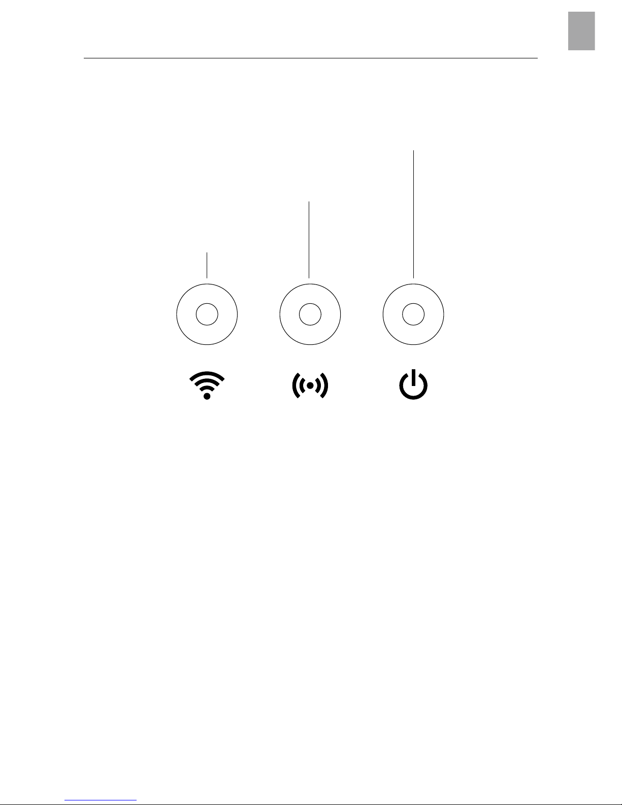
LED-Display:
Power-LED
Connection-LED
Internet-LED
1
Internet LED:
Green: Connected with router and server
Yellow: Hotspot mode – not connected with router
Red: Not connected
Red flashing: Connected with router; not connected with server
2
Connection LED:
Green flashing: Receiving data
Yellow flashing: Sending data
3
Power LED:
Green: Power On
Green flashing: Booting
Yellow: 1. Factory reset running
2. Error (restart required)
Yellow flashing: Software update
Red: Fatal error (restart required)
5
EN
Page 6
3. INITIAL OPERATION
Contents:
– Gateway unit
– Power supply unit
– Ethernet-cable
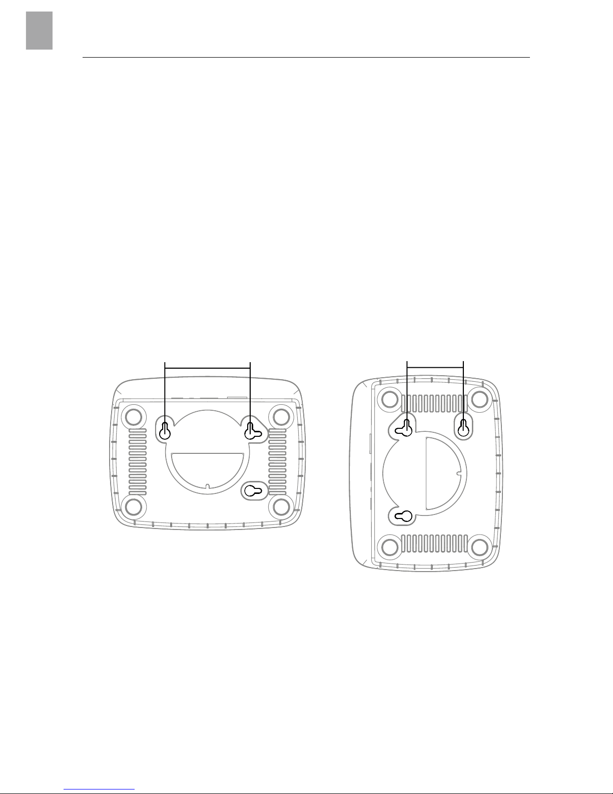
To mount on the wall (optional):
The two screws (not supplied) for attaching the Gateway have to be screwed
into place A horizontally 75 mm / B vertically 50 mm apart and the screw head
diameter must not exceed 8 mm.
75 mm
A
50 mm
B
1. Screw the screws into the wall A 75 mm / B 50 mm apart.
2. Attach the Gateway.
6
EN
Page 7

To commission the smart Gateways:
An Internet connection is required for installation of the Gateway.
The Gateway can be connected to the Internet via ethernet or Wi-Fi.
4
1. Connect the power supply unit to a mains socket.
2. Connect the power supply cable to the plug socket
4
of the Gateway.
3. Select one of the following options:
To connect via ethernet cable / To connect to a Wi-Fi network
7
EN
Page 8

To connect via ethernet cable (recommended):
1. Connect the Gateway with the provided network cable to your router.
The software for your Gateway is now being updated. This process can
take up to 15 minutes (depending on your Internet connection).
Once the Internet-LED and the Power LED illuminate green permanently,
the Gateway is up to date. It can now be included in the App.
2. Download the GARDENA smart system app from the Apple App Store
or the Google Play Store.
3. Follow the instructions in the App.
8
EN
Page 9

To connect to a Wi-Fi network:
If the Gateway is neither connected to the router via a LAN cable nor
integrated into another Wi-Fi network, the Gateway automatically provides
a configuration network after approx. 1 to 2 minutes after startup.
The configuration network is activated as long as the Internet LED
permanently illuminates yellow.
The configuration network remains active for 15 minutes. After the
15 minutes have elapsed (or if the Gateway was previously configured
to another Wi-Fi network that is no longer available), the configuration
network can be reactivated by briefly pushing the reset button 7.
9
EN
Page 10

To configure the Wi-Fi network with an iOS device (iPhone, iPad):
Wait until the Internet LED illuminates yellow permanently (the configuration
network is activated).
1. Open the Apple Home App (this is located by default on your
mobile iOS device).
2. Select “Add accessory”.
3. Scan the HomeKit label on the bottom side of the Gateway.
4. Wait until the Internet LED illuminates green permanently.
The software for your Gateway is now being updated.This process
can take up to 15 minutes (depending on your Internet connection).
Once the Internet LED and the Power LED illuminate green permanently,
your Gateway is up to date. It can now be included in the App.
5. Download the GARDENA smart system app from the Apple App Store.
6. Follow the instructions in the App.
10
EN
Page 11

To configure the Wi-Fi network with another device:
Wait until the Internet LED illuminates yellow permanently
(the configuration network is activated).
To establish a connection via Wi-Fi, you need your Gateway ID.
The Gateway ID can be read on the sticker on the underside of the
Gateway. You will also need the password for your Wi-Fi network.
1. Connect to the GARDENA configuration network. To do this,
go to the Wi-Fi settings on your smartphone, tablet, or computer.
The Gateway should now be displayed there as an available
Wi-Fi network.
The network name starts with “GARDENA_config”.
2. Open the URL:
http://10.0.0.1
in your preferred Internet browser.
You should now see the Gateway Interface.
11
EN
Page 12

Name
GARDENA hotspot network:
GARDENA_config(9eb7)
Password
GARDENA hotspot network:
55446548
Password Gateway Interface:
9eb74563
Gateway ID: 9eb74563-e89b-12d3-a456-426655446548
3. Login using the first eight digits of your Gateway ID as the password
(see graphic). The Gateway ID is located on the bottom side of the
Gateway.
4. Select your home Wi-Fi network under Wi-Fi Network.
Then your Gateway is connected with the Internet.
5. Enter your network password and confirm your settings. Wait until the
Internet LED illuminates green permanently.
The software for your Gateway is now being updated.This process
can take up to 15 minutes (depending on your Internet connection).
Once the Internet LED and the Power LED illuminate green permanently,
your Gateway is up to date. It can now be included in the App.
6. Download the GARDENA smart system App from the Google Play
Store.
7. Follow the instructions in the App.
12
EN
Page 13

Note: Because the GARDENA configuration network does not have its
own Internet access, your device may automatically leave the GARDENA
configuration network or may displays an error message. In this case, you
must allow a connection without Internet access to be maintained in the
settings of your device.
Also, make sure JavaScript is activated and browser cookies are accepted, in
order to display the page correctly. Connecting the Gateway is not supported
by Internet Explorer.
13
EN
Page 14

4. OPERATION
To operate with the GARDENA smart system App:
You can use the GARDENA smart system App to control all smart
system products from anywhere at any time. You can download the free
GARDENA smart system App from the Apple App Store or from the
Google Play Store.
Make sure that the smart Gateway was successfully commissioned
(see 3. INITIAL OPERATION) before connecting it to the app.
All GARDENA smart products are integrated via the app. Follow the
instructions inside the App.
14
EN
Page 15

Factory Reset:
7
The smart Gateway will be reset to the factory settings.
You may need to use the reset function if for example you want to link your
Gateway to a new Wi-Fi network.
1. Disconnect the Gateway from the power supply.
2. Press and hold down the Reset key
7
; reconnect the Gateway to the
power supply and wait until the Power-LED lights up yellow.
3. Release the Reset key
7
and wait until the Power-LED lights up green.
15
EN
Page 16

5. MAINTENANCE
To clean the Gateway:
No caustic / abrasive cleaning agents should be used.
v Clean Gateway with a damp cloth (do not use solvent).
6. STORAGE
To put into storage:
The product must be stored away from children.
v Do not stow the product outdoors if not in use.
Disposal:
(in accordance with RL2012/19/EC)
The product must not be disposed of to normal household waste.
It must be disposed of in line with local environmental regulations.
IMPORTANT!
Dispose of the product through or via your municipal recycling collection
centre.
16
EN
Page 17

7. TROUBLESHOOTING
Problem:
The internet LED flashes red.
Possible Cause:
The Gateway does not reach the required ports.
Remedy:
Outgoing connections from the Gateway must be able to reach the following
ports in the Internet and / or your Router. (Usually no configuration needs to be
changed, this list is a reference for advanced users.):
• 53 TCP / UDP (DNS)
• 67/68 UDP (DHCP)
• 123 TCP / UDP (NTP)
• 80 TCP (HTTP)
• 443 TCP (HTTPS)
NOTE: For any other malfunctions please contact the
GARDENA service department. Repairs must only be done
by GARDENA service departments or specialist dealers
approved by GARDENA.
17
EN
Page 18

8. TECHNICAL DATA
Unit Value (Art. 19005-20)
Operation temperature range
(indoors)
°C 0 to + 40
Internal SRD:
Frequency range MHz 863 – 870
Maximum power mW 25
Free field radio range m (approx.) 100
Wi-Fi
Frequency range MHz 2400 – 2483.5
Maximum power mW 100
Standards supported IEEE 802.11b/g/n
Ethernet
Port 1 LAN port via RJ45 socket
Data connection Standard Ethernet 10/100 Base-T
Power supply unit
Mains voltage V (AC) 100 – 240
Mains frequency Hz 50 – 60
Max. output voltage V (DC) 5
Rated output current A 1
Input ratings of the Gateway unit V (DC) / A 5 / 1
Dimensions (W x H x D) mm 57 x 128 x 58
Weight g 120
EC Declaration of Conformity:
Hereby, GARDENA Manufacturing GmbH declares that the radio equipment
type (Art. 19005) is in compliance with directive 2014/53/EU.
The full text of the EC declaration of conformity is available at the following
internet address:
http://www.gardena.com/int/support/safety-regulations
18
EN
Page 19

9. SERVICE / WARRANTY
Service:
Please contact the address on the back page.
Warranty statement:
In the event of a warranty claim, no charge is levied to you for the services
provided.
GARDENA Manufacturing GmbH grants a warranty for all original GARDENA
new products for two years from the date of original purchase from the retailer,
provided that the devices have been for private use only. This manufacturer’s
warranty does not apply to products acquired second hand.
This warranty includes all significant defects of the product that can be proved
to be material or manufacturing faults.
This warranty is fulfilled by supplying a fully functional replacement product
or by repairing the faulty product sent to us free of charge; we reserve the
right to choose between these options. This service is subject to the following
provisions:
• The product has been used for its intended purpose as per the recommen-
dations in the operating instructions.
• Neither the purchaser nor a third party has attempted to open or repair the
product.
• Only Original GARDENA replacement parts and wear parts have been used
for operation.
• Presentation of the receipt
Normal wear and tear of parts and components (such as blades, blade fixing
parts, turbines, light bulbs, V-belts / toothed belts, impellers, air filters, spark
plugs), visual changes, wear parts and consumables are excluded from the
warranty.
This manufacturer’s warranty is limited to replacement and repair of products
in accordance with the abovementioned conditions. The manufacturer’s warranty does not constitute an entitlement to lodge other claims against us as
a manufacturer, such as for damages. This manufacturer’s warranty does not,
of course, affect statutory and contractual warranty claims against the dealer /
retailer.
The manufacturer’s warranty is governed by the law of the Federal Republic of
Germany.
In case of a warranty claim, please return the faulty product, together with
acopy of the receipt and a description of the fault, with postage paid to the
service address.
19
EN
Page 20

20
EN
Product liability:
In accordance with the German Product Liability Act, we hereby expressly
declare that we accept no liability for damage incurred from our products
where said products have not been properly repaired by a GARDENA
approved service partner or where original GARDENA parts or parts authorised by GARDENA were not used.
Open Source Software:
This device contains open source software. GARDENA hereby offers to
deliver, upon request, a copy of the complete corresponding source code
for the copyrighted open source software packages used in this product
for which such offer is requested by the respective licenses. This offer is valid
up to three years after product purchase to anyone in receipt of this information. To obtain the source code, please write in English, German or French to:
smart.open.source@husqvarnagroup.com
Page 21

21
Deutschland /Germany
GARDENA
Manufacturing GmbH
Central Service
Hans
-
Lorenser-Straße 40
D
-
89079 Ulm
Produktfragen:
(+49) 731 490
-
123
Reparaturen:
(+49) 731 490
-
290
service
@gardena.com
Albania
COBALT Sh.p.k.
Rr. Siri Kodra
1000 Tirana
Argentina
Husqvarna Argentina S.A.
Av.del Libertador 5954
–
Piso 11–Torre B
(C1428ARP) Buenos Aires
Phone: (+54) 11 5194 5000
info.gardena
@
ar.husqvarna.com
Armenia
Garden Land Ltd.
61 Tigran Mets
0005 Yerevan
Australia
Husqvarna Australia Pty. Ltd.
Locked Bag 5
Central Coast BC
NSW 2252
Phone: (+61) (0) 2 4352 7400
customer.service
@
husqvarna.com.au
Austria /Österreich
Husqvarna Austria GmbH
Industriezeile 36
4010 Linz
Tel.: (+ 43) 732 77 01 01
-
485
service.gardena
@
husqvarnagroup.com
Azerbaijan
Firm Progress
a. Aliyev Str. 26A
1052 Baku
Belgium
Husqvarna België nv/ sa
Gardena Division
Rue Egide Van Ophem 111
1180 Uccle / Ukkel
Tel.: (+32) 2 720 9212
info
@gardena.be
Bosnia / Herzegovina
SILK TRADE d.o.o.
Industrijska zona Bukva bb
74260 Tešanj
Brazil
Husqvarna do Brasil Ltda
Av. Francisco Matarazzo,
1400
–
19º andar
São Paulo
–
SP
CEP: 05001
-
903
Tel: 0800
-
112252
marketing.br.husqvarna
@
husqvarna.com.br
Bulgaria
AGROLAND България АД
бул. 8 Декември, №13
Офис 5
1700 Студентски град
София
Тел.: (+ 359) 2466 69 10
info
@agroland.eu
Canada /USA
GARDENA Canada Ltd.
100 Summerlea Road
Brampton, Ontario L6T 4X3
Phone: (+1) 905 792 9330
info
@gardenacanada.com
Chile
Maquinarias Agroforestales
Ltda. (Maga Ltda.)
Santiago, Chile
Avda. Chesterton
# 8355 comuna Las Condes
Phone: (+56) 2 202 4417
Dalton
@maga.cl
Zipcode: 7560330
China
Husqvarna (Shanghai)
Management Co., Ltd.
富世华(上海)管理有限公司
3F, Benq Square B,
No207, Song Hong Rd.,
Chang Ning District,
Shanghai, PRC. 200335
上海市长宁区淞虹路207号明
基广场B座3楼,邮编:200335
Colombia
Husqvarna Colombia S.A.
Calle 18 No. 68 D
-
31, zona
Industrial de Montevideo
Bogotá, Cundinamarca
Tel. 571 2922700 ext. 105
jairo.salazar
@
husqvarna.com.co
Costa Rica
Compania Exim
Euroiberoamericana S.A.
Los Colegios, Moravia,
200 metros al Sur del Colegio
Saint Francis
–
San José
Phone: (+506) 297 6883
exim_euro
@racsa.co.cr
Croatia
Husqvarna Austria GmbH
Industriezeile 36
4010 Linz
Tel.: (+ 43) 732 77 01 01
-
485
service.gardena
@
husqvarnagroup.com
Cyprus
Med Marketing
17 Digeni Akrita Ave
P.O. Box 27017
1641 Nicosia
Czech Republic
Husqvarna Česko s.r.o.
Türkova 2319 /5b
149 00 Praha 4 – Chodov
Bezplatná infolinka:
800 100425
servis
@cz.husqvarna.com
Denmark
GARDENA DANMARK
Lejrvej 19, st.
3500 Værløse
Tlf.: (+45) 70 26 47 70
husqvarna
@husqvarna.dk
www.gardena.com/ dk
Dominican Republic
BOSQUESA, S.R.L
Carretera Santiago Licey
Km. 5 ½
Esquina Copal II.
Santiago
Dominican Republic
Phone: (+809) 736-0333
joserbosquesa
@claro.net.do
Ecuador
Husqvarna Ecuador S.A.
Arupos E1-181 y 10 de
Agosto
Quito, Pichincha
Tel. (+593) 22800739
francisco.jacome
@
husqvarna.com.ec
Estonia
Husqvarna Eesti OÜ
Valdeku 132
EE-11216 Tallinn
info
@gardena.ee
Finland
Oy Husqvarna Ab
Gardena Division
Lautatarhankatu 8 B/ PL 3
00581 HELSINKI
www.gardena.fi
France
Husqvarna France
9/11 Allée des pierres mayettes
92635 Gennevilliers Cedex
France
http://www.gardena.com/ fr
N° AZUR : 0 810 00 78 23
(Prix d’un appel local)
Georgia
Transporter LLC
8/57 Beliashvili street
0159 Tbilisi, Georgia
Phone: (+995) 322 14 71 71
Great Britain
Husqvarna UK Ltd
Preston Road
Aycliffe Industrial Park
Newton Aycliffe
County Durham
DL5 6UP
info.gardena
@
husqvarna.co.uk
Greece
Π.ΠΑΠΑΔΟΠΟΥΛΟΣ ΑΕΒΕ
Λεωφ. Αθηνών 92
Αθήνα
Τ.Κ.104 42
Ελλάδα
Τηλ. (+30) 210 5193100
info
@papadopoulos.com.gr
Hungary
Husqvarna Magyarország Kft.
Ezred u. 1
-
3
1044 Budapest
Telefon: (+36) 1 251
-
4161
vevoszolgalat.husqvarna
@
husqvarna.hu
Iceland
Ó. Johnson & Kaaber
Tunguhalsi 1
110 Reykjavik
ooj
@ojk.is
Ireland
Husqvarna UK Ltd
Preston Road
Aycliffe Industrial Park
Newton Aycliffe
County Durham
DL5 6UP
info.gardena
@
husqvarna.co.uk
Italy
Husqvarna Italia S.p.A.
Via Santa Vecchia 15
23868 VALMADRERA (LC)
Phone: (+39) 0341.203.111
assistenza.italia
@
it.husqvarna.com
Japan
KAKUICHI Co. Ltd.
Sumitomo Realty &
Development Kojimachi
BLDG., 8F
5
-
1 Nibanncyo
Chiyoda
-
ku
Tokyo 102
-
0084
Phone: (+81) 33 264 4721
m_ishihara
@kaku
-
ichi.co.jp
Kazakhstan
LAMED Ltd.
155/1, Tazhibayevoi Str.
050060 Almaty
IP Schmidt
Abayavenue 3B
110 005 Kostanay
Korea
Kyung Jin Trading CO.,LTD.
107-4, SunDuk Bld.,
YangJae-dong,
Seocho-gu,
Seoul, (zipcode: 137-891)
Phone: (+82) (0) 2 574-6300
Kyrgyzstan
Alye Maki
av. Moladaya Guardir J 3
720014
Bishkek
Latvia
Husqvarna Latvija SIA
Ulbrokas 19A
LV-1021 Rīga
info
@gardena.lv
Lithuania
UAB Husqvarna Lietuva
Ateities pl. 77C
LT
-
52104 Kaunas
info
@
gardena.lt
Luxembourg
Magasins Jules Neuberg
39, rue Jacques Stas
Luxembourg
-
Gasperich 2549
Case Postale No. 12
Luxembourg 2010
Phone: (+352) 40 14 01
api
@neuberg.lu
Mexico
AFOSA
Av. Lopez Mateos Sur # 5019
Col. La Calma 45070
Zapopan, Jalisco
Mexico
Phone: (+52) 33 3818
-
3434
icornejo
@afosa.com.mx
Moldova
Convel S.R.L.
290A Muncesti Str.
2002 Chisinau
Netherlands
Husqvarna Nederland B.V.
GARDENA Division
Postbus 50131
1305 AC ALMERE
Phone: (+31) 36 521 0010
info
@gardena.nl
Neth. Antilles
Jonka Enterprises N.V.
Sta. Rosa Weg 196
P.O. Box 8200
Curaçao
Phone: (+599) 9 76766 55
pgm
@jonka.com
New Zealand
Husqvarna New Zealand Ltd.
PO Box 76
-
437
Manukau City 2241
Phone: (+64) (0) 9 9202410
support.nz
@husqvarna.co.nz
Norway
Husqvarna Norge AS
Gardena Division
Trøskenveien 36
1708 Sarpsborg
info
@gardena.no
Peru
Husqvarna Perú S.A.
Jr. Ramón Cárcamo 710
Lima 1
Tel : (+51) 1 3 320 400 ext. 416
juan.remuzgo
@
husqvarna.com
Poland
Husqvarna
Poland Spółka z o.o.
ul. Wysockiego 15 b
03
-
371 Warszawa
Phone: (+ 48) 22330 9600
gardena
@husqvarna.com.pl
Portugal
Husqvarna Portugal, SA
Lagoa
-
Albarraque
2635
-
595 Rio de Mouro
Tel.: (+351) 21 922 85 30
Fax : (+351) 21 922 85 36
info
@gardena.pt
Romania
Madex International Srl
Soseaua Odaii 117
-
123,
RO 013603 Bucure
ş
ti, S1
Phone: (+ 40) 21 352.76.03
madex
@ines.ro
Russia /Россия
ООО „Хускварна“
141400, Московская обл.,
г. Химки,
улица Ленинградская,
владение 39, стр.6
Бизнес Центр
„Химки Бизнес Парк“,
помещение ОВ02_04
http: //www.gardena.ru
Serbia
Domel d.o.o.
Autoput za Novi Sad bb
11273 Belgrade
Phone: (+381) 118 4888 12
miroslav.jejina
@
domel.rs
Singapore
Hy-Ray PRIVATE LIMITED
40 Jalan Pemimpin
#02
-
08 Tat Ann Building
Singapore 577185
Phone: (+65) 6253 2277
shiying
@hyray.com.sg
Slovak Republic
Husqvarna Česko s.r.o.
Türkova 2319 /5b
149 00 Praha 4 – Chodov
Bezplatná infolinka:
800 154044
servis
@sk.husqvarna.com
Slovenia
Husqvarna Austria GmbH
Industriezeile 36
4010 Linz
Tel.: (+ 43) 732 77 01 01
-
485
service.gardena
@
husqvarnagroup.com
South Africa
Husqvarna
South Africa (Pty) Ltd
Postnet Suite 250
Private Bag X6,
Cascades, 3202
South Africa
Phone: (+27) 33 846 9700
info
@gardena.co.za
Spain
Husqvarna España S.A.
Calle de Rivas nº10
28052 Madrid
Phone: (+34) 91 70805 00
atencioncliente
@gardena.es
Suriname
Agrofix n.v.
Verlengde Hogestraat #22
Phone: (+597) 472426
agrofix
@sr.net
Pobox : 2006
Paramaribo
Suriname
–
South America
Sweden
Husqvarna AB
Gardena Division
S
-
561 82 Huskvarna
gardenaorder
@husqvarna.se
Switzerland /Schweiz
Husqvarna Schweiz AG
Consumer Products
Industriestrasse 10
5506 Mägenwil
Phone: (+41) (0) 62 887 37 90
info
@gardena.ch
Turkey
Dost Bahçe Dış Ticaret
Mümessillik A.Ş
Yunus Mah. Adil Sok. No:3
Ic Kapi No: 1 Kartal
34873 Istanbul
Phone: (+90) 216 3893 939
info
@dostbahce.com.tr
Ukraine / Україна
ТОВ «Хускварна Україна»
вул. Васильківська, 34,
офіс 204
-
г
03022, м. Київ
Тел. (+38) 044 498 39 02
info
@gardena.ua
Uruguay
FELI SA
Entre Ríos 1083 CP 11800
Montevideo
–
Uruguay
Tel: (+ 598) 22 03 18 44
info
@felisa.com.uy
Venezuela
C
orporación Casa y Jardín C.A.
Av. Caroní, Edif. Trezmen, PB.
Colinas de Bello Monte.
1050 Caracas.
Tlf: (+58) 212 992 33 22
info
@casayjardin.net.ve
0000
-
20.960.08/ 0618
©
GARDENA
Manufacturing GmbH
D-89070 Ulm
http: //www.gardena.com
19005-20.961.01/0319
© GARDENA
Manufacturing GmbH
D-89070 Ulm
http://www.gardena.com
 Loading...