

Ganz ZR-DHC830NP, ZR-DHC1630NP Instruction Manual
ZR-DHC830NP/ZR-DHC1630NP

Introduction
Introduction
Introduction
Thank you for purchasing the GANZ ZR-DHC1630NP/ZR-DHC830NP.
This DVR is produced using the most advanced CBC technology and its quality is
guaranteed by strict reliability and compatibility testing.
This manual provides necessary information for the correct use of this product and also
contains some useful tips.
Please read this manual thoroughly before using your DVR in order to prevent
possible malfunctions due to any mishandling.
This manual applies to the ZR-DHC1630NP/ZR-DHC830NP only.
This manual describes the external features of the ZR-DHC1630NP/ZR-DHC830NP, part
names, correct connection methods for supported domes or pan/tilt receivers, control
devices, peripheral devices and the system setup instructions. It is important to note here
that some features, figures, pictures and references can only be applied to just one model:
ZR-DHC1630NP/ZR-DHC830NP.
• CBC cannot be held responsible if the DVR is damaged due to the use of noncompatible devices with this product. If you have any doubts, please check.
• CBC cannot be held responsible if the DVR is damaged due to the product being
disassembled or modified by the user.
• This product is qualified for both domestic and industrial use. This product is qualified
under the Radio Equipment Requirements of Korea and acquired international certification
including CE (Europe) and FCC (USA).
Notice
Notice
Notice
This manual is written based on the 16 Channel DVR (Model :
ZR-DHC1630NP). The contents may change according to the
number of channels and the types of exterior equipment.

All copyrights of this manual are reserved by CBC Co., Ltd.
Copyright
©
2006
Any reproduction or republishing of this manual for commercial purposes is prohibited.
It is prohibited to transfer this manual via online media such as, but not limited to, the
Internet. It is also prohibited to post, distribute or translate this manual without permission
from CBC.
CBC is not held responsible if the DVR is damaged as a result of improper handling by a
user unaware of how to operate this product or who did not consult this manual before
attempting to operate the product.
CBC reserves the right to change the contents of this manual without notice.
CBC reserves all copyrights of registered trademarks in this manual.
Copyrights
Copyrights
Copyrights

Caution
Caution
Caution
Please be aware of the following precautions before installing the DVR.
• Avoid positioning the ZR-DHC1630NP/ZR-DHC830NP in any place where the
unit may come into contact with moisture, dust, or soot.
• Avoid placing in direct sunlight or near heating appliances.
• Keep the product away from electric shock or magnetic substances.
• Avoid temperature extremes (recommended operation temperature is between
0°C and ~40°C).
• Do not place any conductive material through the ventilation grills.
• Keep the system turned off before installation.
• Ensure that enough space is left for cable connections.
• Place the system on a solid surface with sufficient air ventilation. Avoid any
surface that vibrates.
• Placing the system near electronic devices such as radio or TV may cause
the product to malfunction.
• Do not disassemble the product without seeking assistance from the supplier.
• Do not place any heavy object on the system.
• Please keep cleaning the fan filter of front panel.
CALIFORNIA USA ONLY
This Perchlorate warning applies only to primary CR (Manganese
Dioxide) Lithium coin cells in the product sold or distributed
ONLY in California USA.
“Perchlorate Material – special handing may apply, See
www.dtsc.ca.gov/hazardouswaste/perchlorate.”
The following are warnings and cautions to ensure user safety and
prevent property damage. Please read the information below thoroughly.
Warning and caution signs
If you are not aware of this
caution, you may be injured
or cause property loss.
If you are not aware of this
warning, you may be
seriously injured or be killed.
Warning
Caution
Safety Warnings and Cautions
Safety Warnings and Cautions
Safety Warnings and Cautions
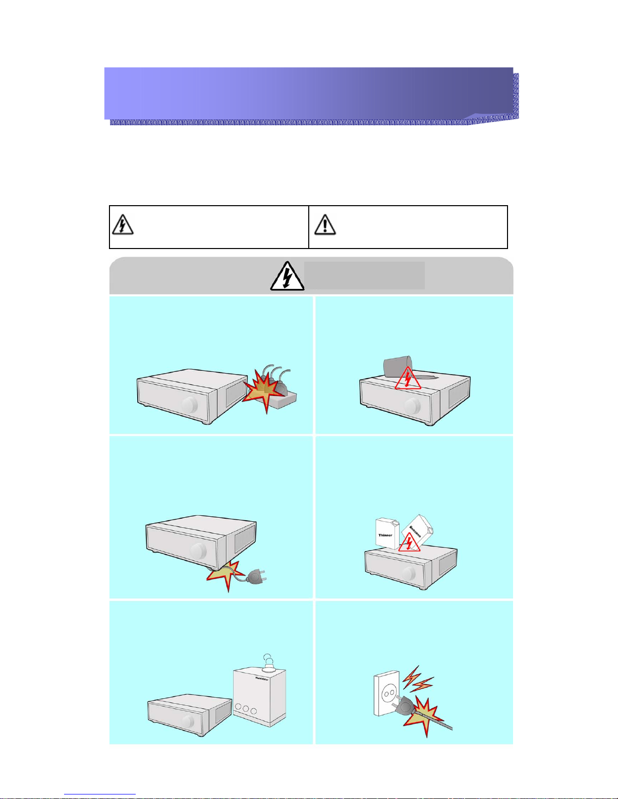
Turn off the system before installing the system.
Do not plug in several electric devices to the same
outlet.
y This may cause heating, fire or electric shock.
Do not place any liquid container on the system,
such as water, coffee or any other beverage.
• If liquid is poured onto the system, it can cause a
system malfunction or fire.
Prevent the power cable from being severely bent
or pressed by a heavy object.
• This may cause fire.
Clean the dust around the system on a regular
basis. When cleaning the system, always use dry
cloth. Do not use wet cloth or other organic
solvents.
• This may damage the surface of the system and
can cause system malfunction or electric shock.
Avoid any place with moisture, dust, or soot.
• This can cause fire or electric shock.
When pulling the power cable from the plug, do
so gently. Do not touch the plug with wet hands
and avoid using the plug if the holes on the outlet
are too loose.
• This may cause fire or electric shock.
Warning
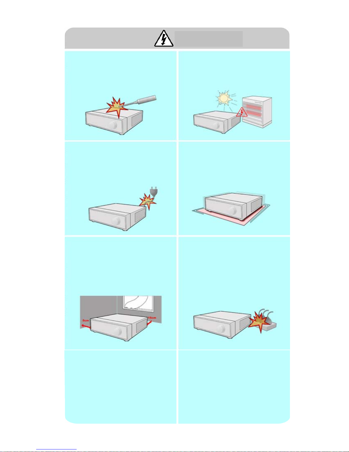
Do not attempt to disassemble, repair or modify
the system on your own. It is extremely
dangerous due to high voltage running through
the system.
• This may cause fire, electric shock or serious
injuries.
Install the system in a cool place without direct
sunlight and always maintain room temperature.
Avoid candlelight and heat-generating devices
such as a heater. Keep the system away from
high-traffic areas.
• This may cause fire.
Check for any danger signs such as a moist floor,
loosened or damaged power cable or unstable
surface. If you encounter any problems, ask your
dealer for assistance.
• This may cause fire or electric shock.
Install the system on a flat surface with sufficient
air ventilation. Do not place the system on
elevated surface.
• This may cause system malfunction or serious
injuries.
Keep at least 15cm between the back of the
system and the wall for the cables connected into
the system. Otherwise, the cables may be bent,
damaged or cut.
• This may cause fire, electric shock, or injuries.
The power outlet must be placed on a ground,
and the voltage range must be within 10% of the
voltage rate. Do not use the same outlet with a
hair dryer, iron, refrigerator or any heating
appliances.
• This may cause fire, heating and electric shock.
Warning
When the system’s battery is depleted, you must
replace it with the same or equivalent type of
battery specified by the manufacturer. Depleted
batteries should be discarded according to
manufacturer’s instructions.
• This may cause an explosion.
If the system’s HDD has exceeded its life span,
you may not be able to recover any data stored
inside the HDD. If the video on the system screen
appears ‘damaged’ while playing a recording
stored inside the system’s HDD, it must be
replaced with a new one. Ask for an engineer’s
assistance for HDD replacement from your dealer.
• CBC is not responsible for deleted data caused
by user mishandling.
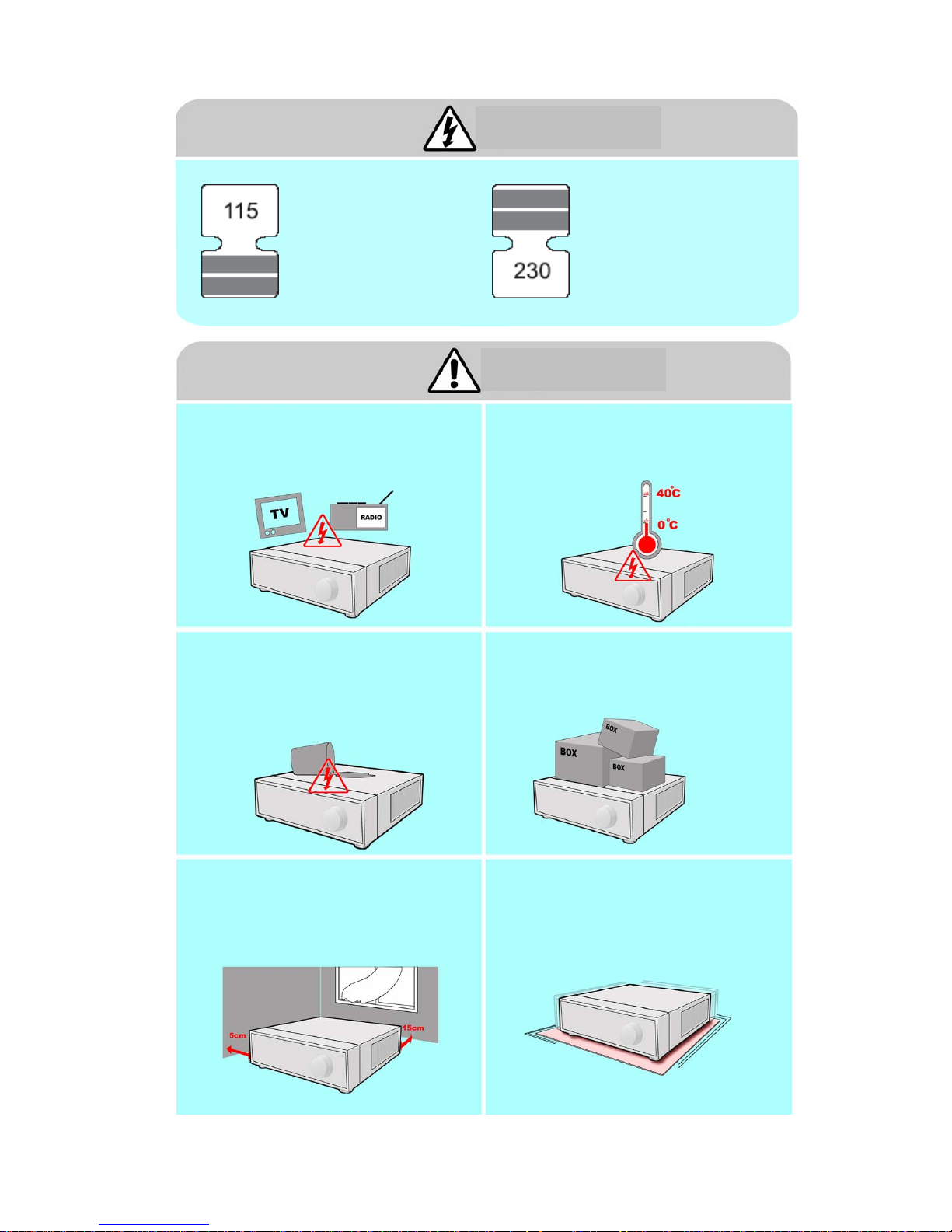
Do not install the system in an area featuring high
magnetic, electric wave or wireless devices such
as radio or TV.
• Install the system in a place without magnetic
objects, electric frequencies or vibration.
Install the system in a place with appropriate
moisture and temperature levels.
• Avoid installing the system at high (over 40℃)
or low (under 0℃) temperatures.
Prevent any substances from entering into the
system.
• This may cause system malfunction.
Do not place any heavy objects on the system.
• This may cause system malfunction.
Install the system in a place with sufficient air
ventilation.
• Keep at least 15cm distance between the back
of the system and the wall, and at least 5cm
distance between the side of the system and any
walls.
Install the system on a stable and level surface.
• The system may not operate properly.
Caution
Warning
Power setup
Connect with AC115V if the
AC selector appears as shown
here.
Connect with AC230V if the
AC selector appears as
shown here.
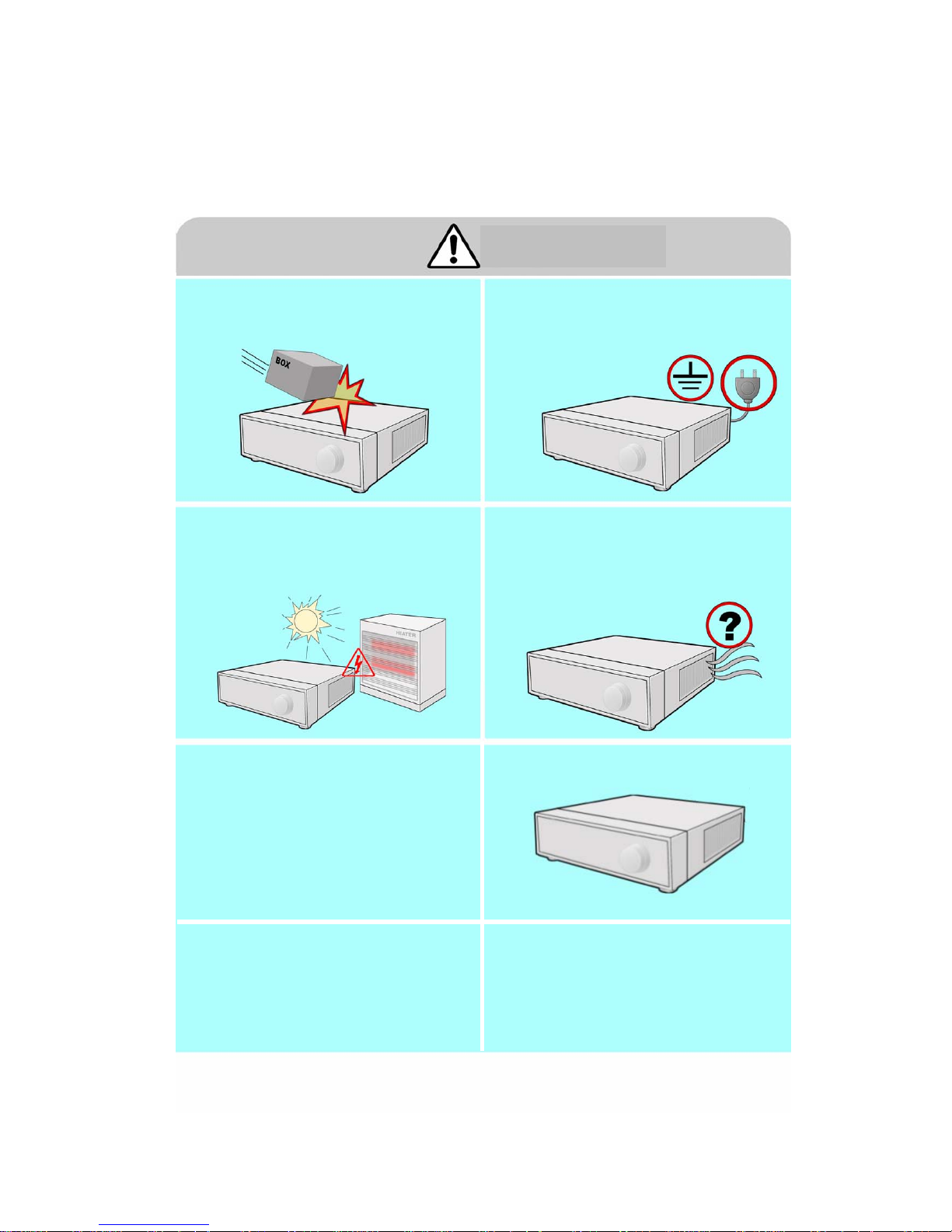
The system can be damaged as a result of strong
impact or vibration. Avoid throwing objects within
the vicinity of the system.
The outlet must be placed on the ground.
Avoid direct sunlight or any heating appliances.
If there is strange sound or smell, unplug the
power cable immediately and contact the service
center.
• This may cause fire or electric shock.
Ventilate the air inside the system operation room
and tighten the system cover firmly.
• System malfunction may be caused by
inappropriate environment.
In order to maintain stable system performance,
have your system checked regularly by the
service center.
• CBC is not held responsible for system
breakdown caused by user mishandling.
It is recommended to use AVR (automatic voltage
regulator) for stable power supply.
It is recommended to coil the core-ferrite around
the connector of the system to avoid
electromagnetic interference.
Caution
Do not overturn the product when in use.

9
9
Index
Index
1. Installation
User Manual
1.1 System front panel ……………..………………………………………………………12
1.2 System back panel ……………….…………………………………………………13
1.3 Basic connection …………………………………………………………………………15
1.4 Alarm-in connection………………..……………………………………………………16
1.5 Alarm-out connection ……………….…………………………………………………17
1.6 RS485 port connection ……………..………………………………………………… 18
1.7 Network connection …………………………………………………………………19
2.1 Live screen ………………..……………….………………………………………20
2.2 Login menu ……………..………………………………………………………………22
2.3 Picture composition ………………..……………………………………………………23
2.4 System status ……………..……………………………………………………24
2.5 DB drive allocation ………….……………………………………………………26
2.6 Event indication …………………………….………………………………………29
2.7 Full screen display ………………….……………………………………………30
2.8 Display settings ………………………….…………………………………………31
2.9 1 Ch playback …………………………..………………………………………32
2.10 Instant backup ………………………………………..………………………………………33
2.11 Camera picture allocation ……………….…………….……………………………………34
2.12 Pan/tilt mode …………………………………………………………36
2.13 System shutdown …………………………………………………………39
2.14 Virtual keyboard ………………………….…………………………….………………40
2. Live

10
10
4. Search
4.1 Search mode ………………………….………………………………………89
4.2 Select search date and time…………..………..……………………… 91
4.3 Camera selection ………………………………………………………………94
4.4 Playback controls ………………………...………………………………95
4.5 Event search ………………………………….……………………………96
4.6 Picture adjustment ……………………………..……………………………97
4.7 Backup ……………………………………………………………………………101
4.8 Snapshot run ……………………………………………………………………106
4.9 Printing ………………………………………………………………………107
4.10 De-interlace improvement (D1 mode only) ………….………………………109
3. Configuration
3.1 Hardware ………………………………..……………………………………………41
3.1.1 Camera ……………..…………………………………………………… 41
3.1.2 Audio ……………...…………………………………………………………48
3.1.3 Alarm ………….………………………………………………………………49
3.1.4 External monitor ……...………………………………………………50
3.2 Recording …………....…….………………………………………………………51
3.2.1 Recording …………..…….………………………………………………… 51
3.2.2 Schedule …………………………………………………………………52
3.2.3 Storage Calculator ……………………………………………………56
3.3 Event …………………………………………………………………………57
3.3.1 Motion detection ………………………………………………………57
3.3.2 Emergency ………….………………..………………………………………60
3.3.3 Video loss ………………………………………………………………61
3.3.4 E-mail …….…………………………….…………………………………62
3.4 Backup ……………………………………………………………………………64
3.5 Network …………………………………………….……………………… 66
3.5.1 Network ………….……………………………….………………………66
3.5.2 DDNS ………………….…………………………….………………………67
3.5.3 Stream control …………..……………………………………………68
3.5.4 Emergency Monitor ……………………………………………………… 69
3.6 System …………….……………….…………………………………………70
3.6.1 User ………….………………………………………………………………70
3.6.2 Settings …………..…..…………………………………….……………………78
3.6.3 Date/time ….…..………………………………………………………… 84
3.6.4 System information …………………………………………………… 85
3.7 AddOn …………….……………….…………………………………………86
3.7.1 Keypad ………….………………………………………………………………86
3.7.2 POS …………..…….…………………………………….……………………87

11
11
5. Advanced search
5.1 Event search …………………………………………………………………110
5.2 Sequence search …………………………………………………………… 111
5.3 Thumbnail search …………………………………………………………112
5.4 Object search ………………………………………………………………..…113
5.5 POS search …………………………………………………………………… 114
Appendix
1. WebDVR ……………………………………………………………………………….………115
2. Recovery Disk instruction guide …………………………………………………….………118
3. How to do System Recovery on HDD …………………………………………….………120
4. Specifications…………………………………………………………………………………………122
12
12
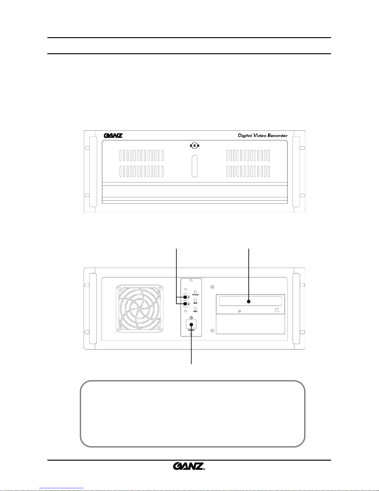
[Note]
• This manual is written based on the 16 channel DVR (Model : ZR-DHC1630NP).
The contents may change according to the number of channels and the types of
exterior equipment.
• The system front and rear panels are subject to change without notice for quality
improvements.
• Please keep cleaning the fan filter of front panel.
☞
☞
Door Closed
Door Open
Power Switch
USB Port
CD/DVD-RW
1. Installation
1.1 System front panel
1.1 System front panel
13
13
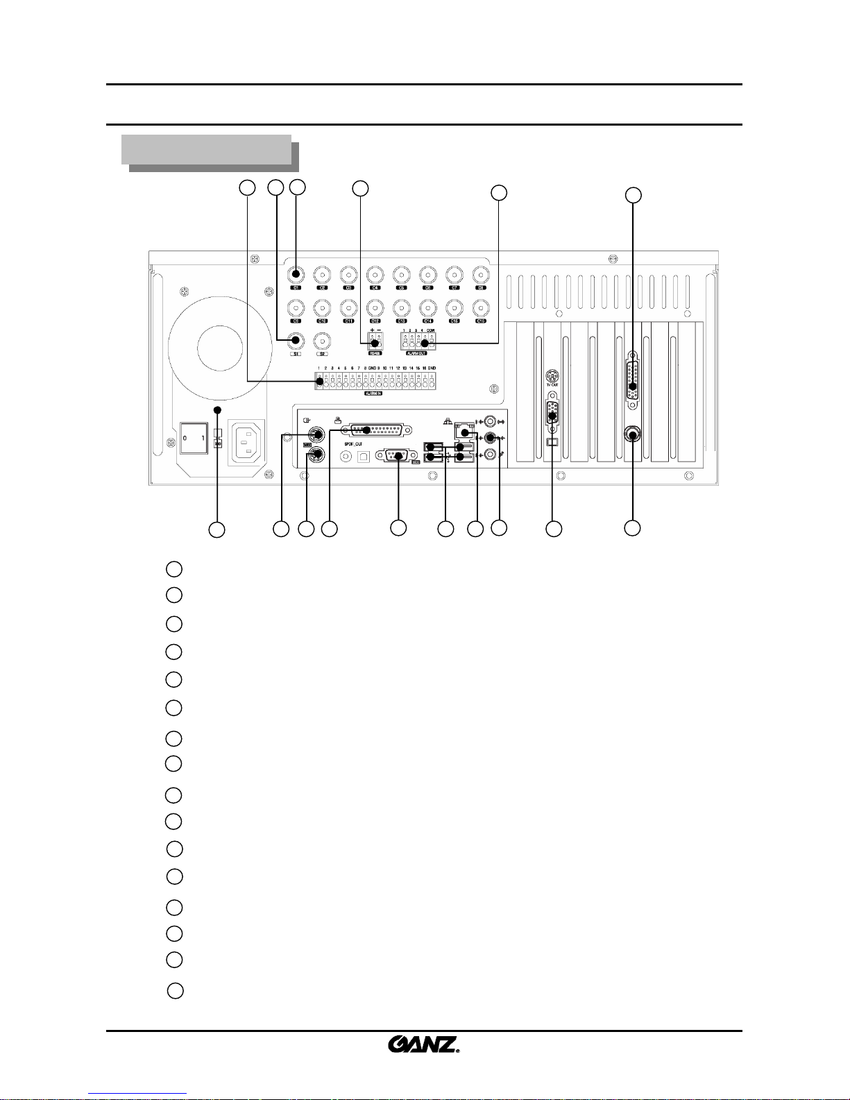
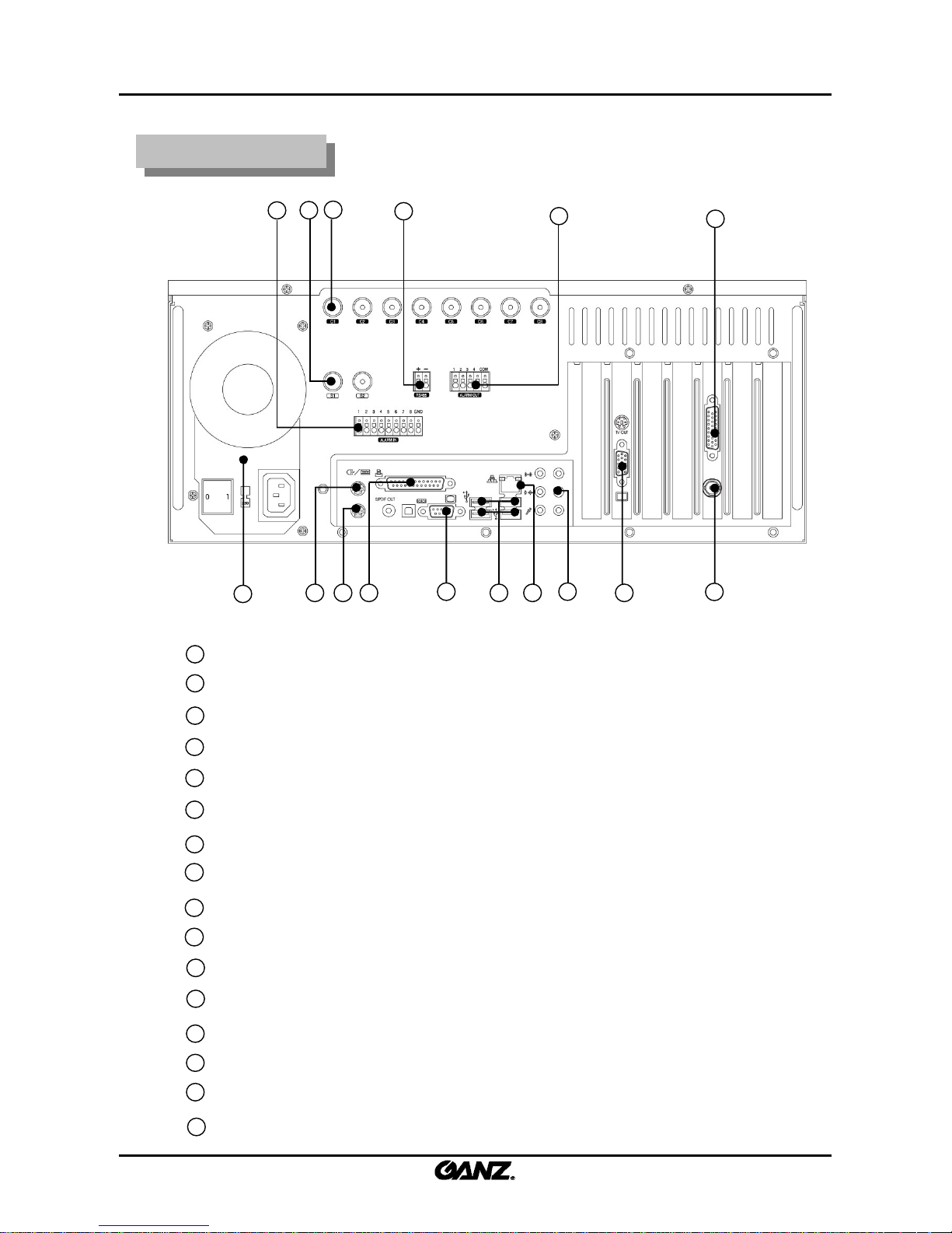
1.2 System back panel
1.2 System back panel
Power Supply (AC 100-120/200-240V, 50/60HZ, 10-5.5A)
Alarm Input (16-Port)
SPOT Monitor Output (2-Port)
Camera Input (16-Port)
RS485 Port
Alarm Output (4-Port)
Audio Input Port
Mouse Input Port (PS/2)
Keyboard Input Port (PS/2)
Printer Port (LPT1)
Serial Port (COM1)
USB Port (Ver. 2.0)
Ethernet Port (100 Mbps)
Audio Output Port
VGA Port
External Monitor Output (supported 16-split screen)
1
2
3
4
5
6
7
8
9
10
11
12
13
14
15
1
4
2
3
5
6
7
8 9 10
11
12 13
14
15
16
16
ZR-DHC1630NP
ZR-DHC1630NP
14
14
Power Supply (AC 100-120/200-240V, 50/60HZ, 10-5.5A)
Alarm Input (16-Port)
SPOT Monitor Output (2-Port)
Camera Input (16-Port)
RS485 Port
Alarm Output (4-Port)
Audio Input Port
Mouse Input Port (PS/2)
Keyboard Input Port (PS/2)
Printer Port (LPT1)
Serial Port (COM1)
USB Port (Ver. 2.0)
Ethernet Port (100 Mbps)
Audio Output Port
VGA Port
External Monitor Output (supported 16-split screen)
1
2
3
4
5
6
7
8
9
10
11
12
13
14
15
1
4
2
3
5
6
7
8 9 10
11
12 13
14
15
16
16
ZR-DHC830NP
ZR-DHC830NP
15
15
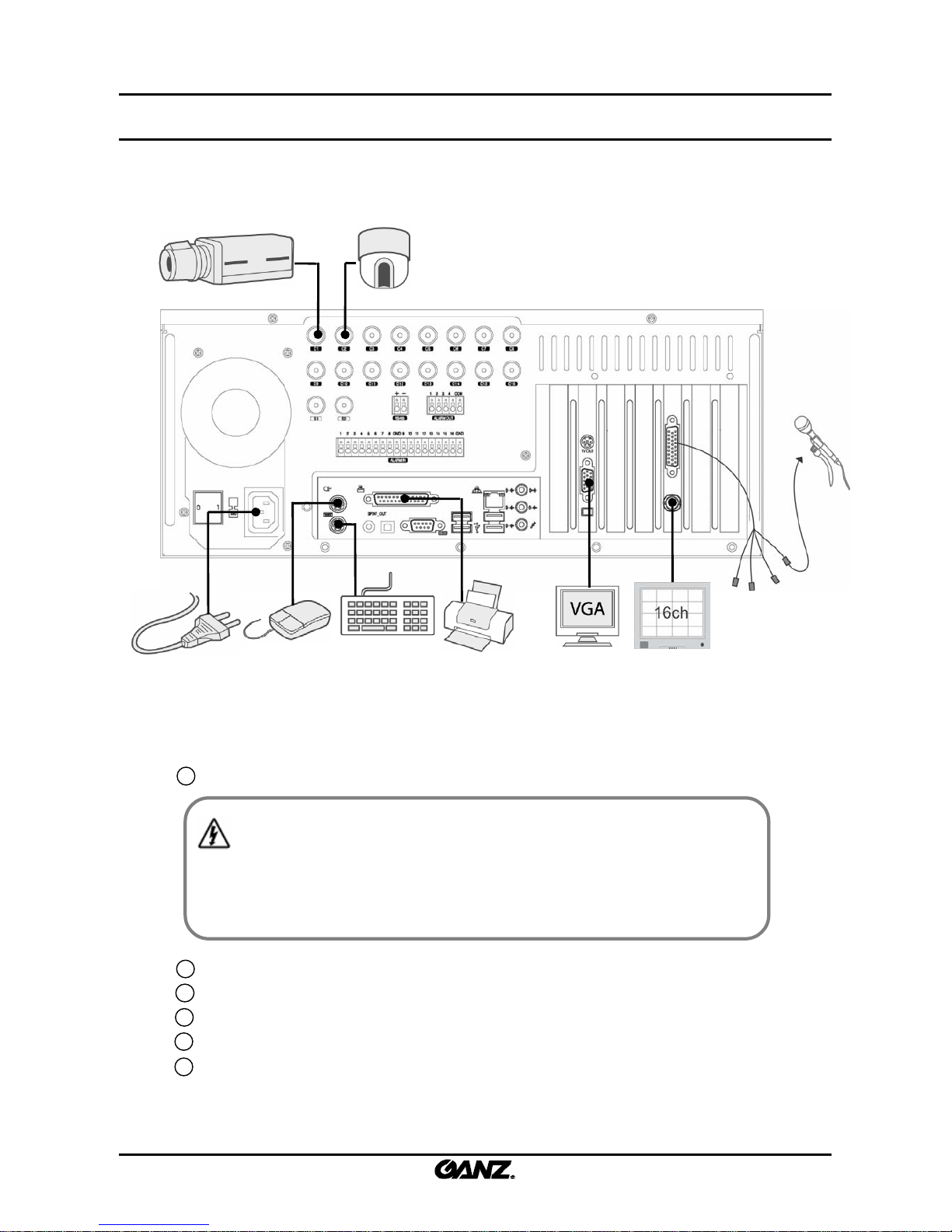
1.3 Basic connection
1.3 Basic connection
Connecting the power cable to the power supply.
1
2
3
4
5
Connect the mouse to the upper PS/2 terminal .
Connect the keyboard to the lower PS/2 terminal.
Connect the VGA monitor to the VGA input on the VGA card.
Connect the camera signal to the BNC terminals (coaxial type).
Connect the Printer to the LPT1 terminal.
[Warning]
• The power cable should be plugged in after all devices are connected. The system will
automatically boot once the power cable is plugged in. The front on/off switch is used
when you reboot the system manually.
6
The devices and cables should be connected to the back panel as shown above.
16
16
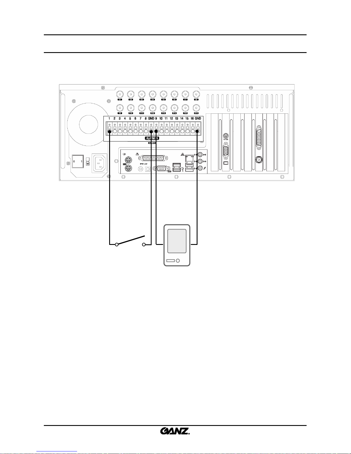
1.4 Alarm
1.4 Alarm--
in connection
in connection
When an event occurs, the sensor device should open or close a mechanical connection to
form a circuit to inform the DVR that it has been activated. The mechanical switch can
connect with either a GND or an alarm input. Each alarm input terminal can be set up as NC
(Normal Close) or NO (Normal Open) in the system configuration.
Sensor connection method
1. Connect the signal line of the sensor device with the alarm input terminal number.
2. Connect the other signal line with the GND.
Input alarmin no. 1
GND GND
Input alarmin no. 9
17
17
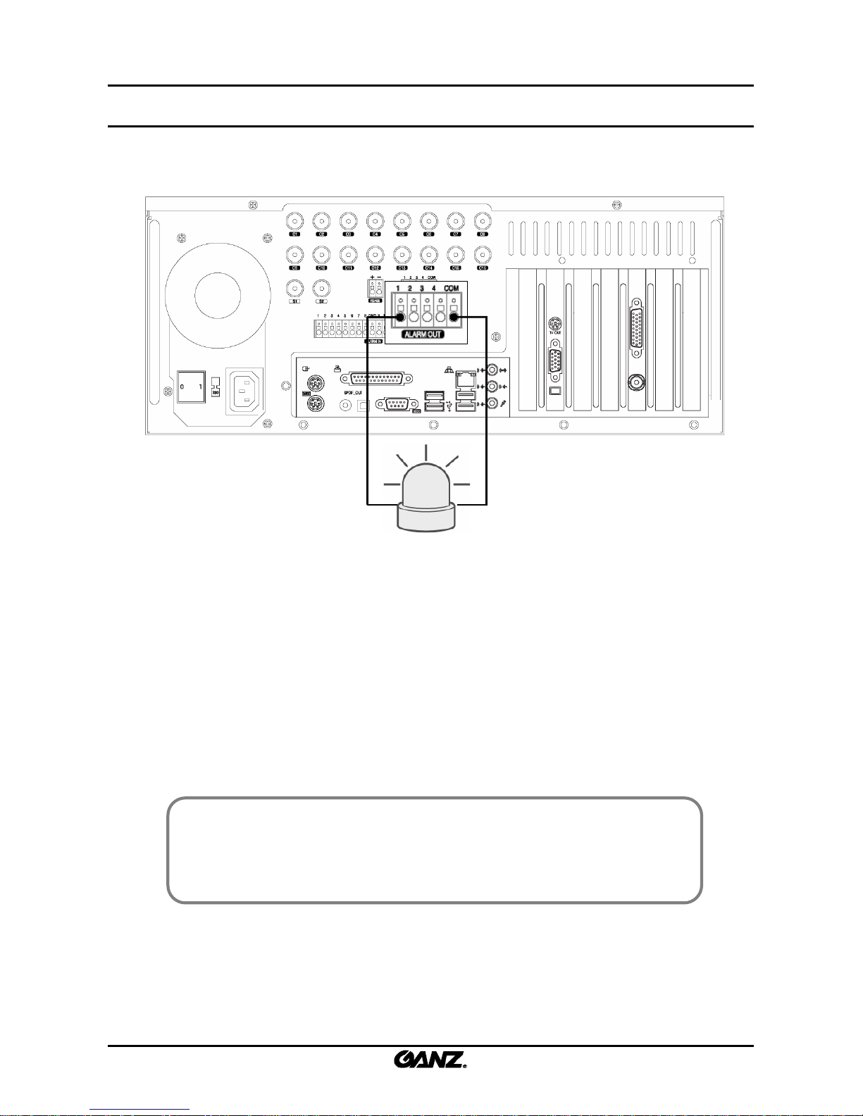
1.5 Alarm
1.5 Alarm--
out connection
out connection
The DVR System can turn an alarm device such as a siren or a light on or off.
The Alarm device can connect to the alarm output and COM terminals. Each alarm output
terminal can be setup as NC (Normal Close) or NO (Normal Open) in the system
configuration.
[Note]
• Connect any alarm device to the alarm-out. When an event occurs in the alarm-in, the
connected alarm output will initiate the alarm device by a mechanical reply completing the
circuit.
☞
☞
Control connection method
1. Connect the Signal line of the alarm device with the alarm output terminal number.
2. Connect another signal line with the COM terminal.
18
18
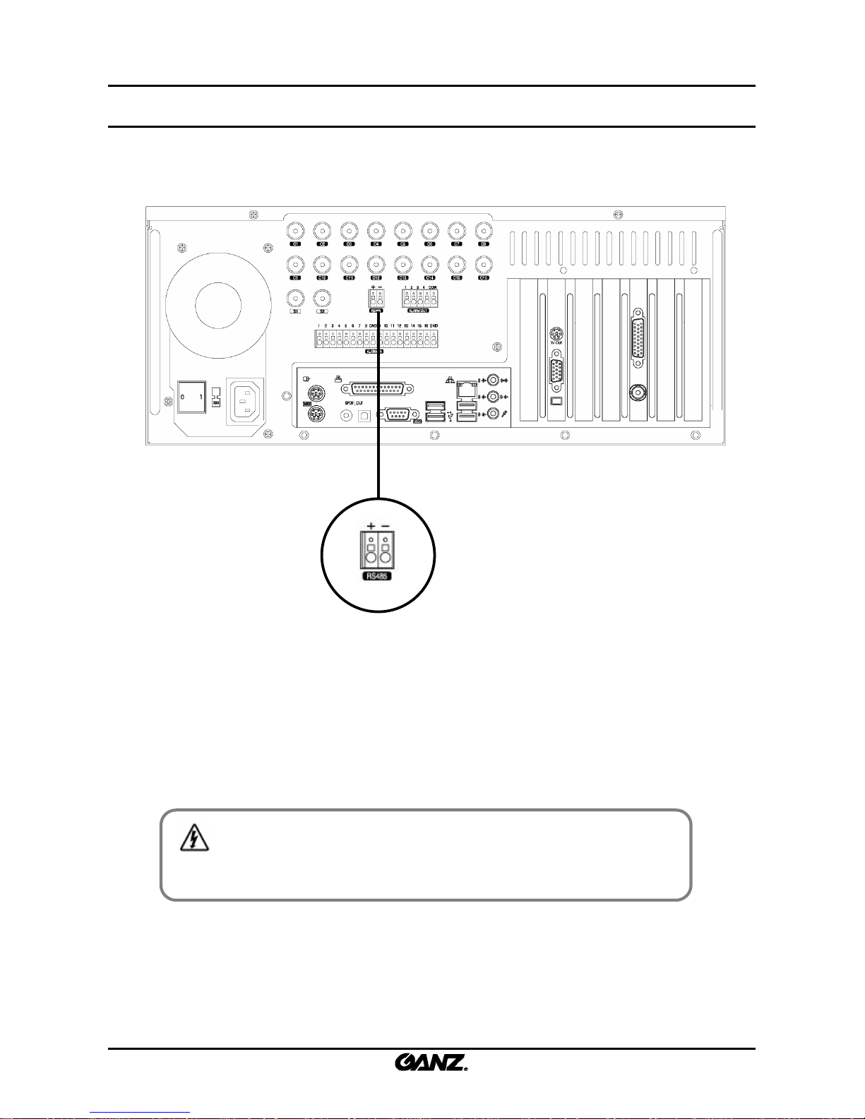
1.6 RS485 port connection
1.6 RS485 port connection
The DVR System and the PTZ device can be controlled using the RS485 interface. The RS485
terminal is provided in the DVR system can be used to control the PTZ camera, speed dome and
other external devices. For the PTZ camera, connect RX+ and TX+ with the (+)RS485 port,
connect RX- and TX- with the (-)RS485 port.
[Warning]
• Make sure that the positive (+) and minus(-) signals have the correct polarity.
Connecting to the wrong side could damage the system.
19
19
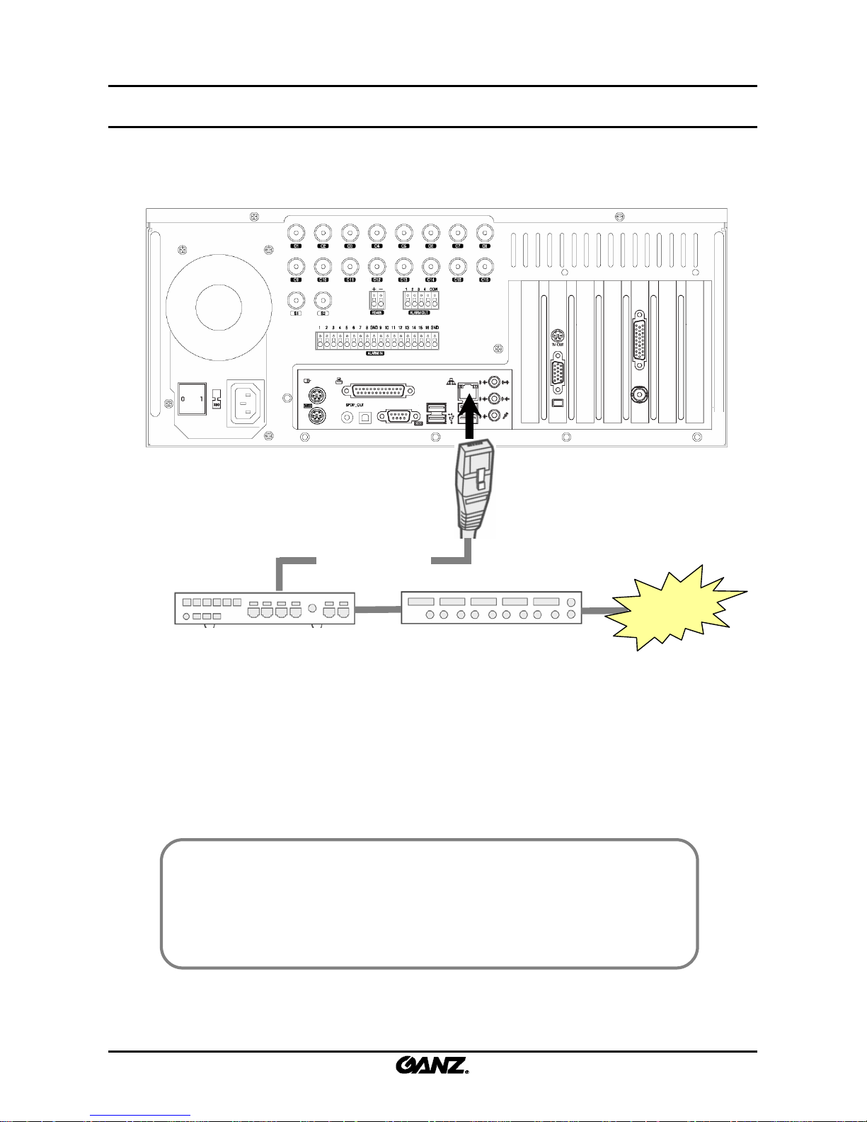
1.7 Network connection
1.7 Network connection
The DVR system support includes the remote control, remote search and remote S/W
upgrade by network. When setting up the network, it is recommended to use the switch hub
with TCP/IP protocol for LAN/WAN.
[Note]
• Please contact your ISP when you connect the DVR system to the network to prevent
network problems.
• Please use the CAT5 cable, which consists of the RJ-45 jack and switch hub (100Mbps), for
the TCP/IP connection.
☞
☞
UTP Cable (CAT5)
LAN/WAN
internet
Switch hub (100Mbps) Router
Network cable connection method
1. Connect the UTP cable with the network port of the system back panel.
2. Connect another UTP cable line with the switch hub.
20
20
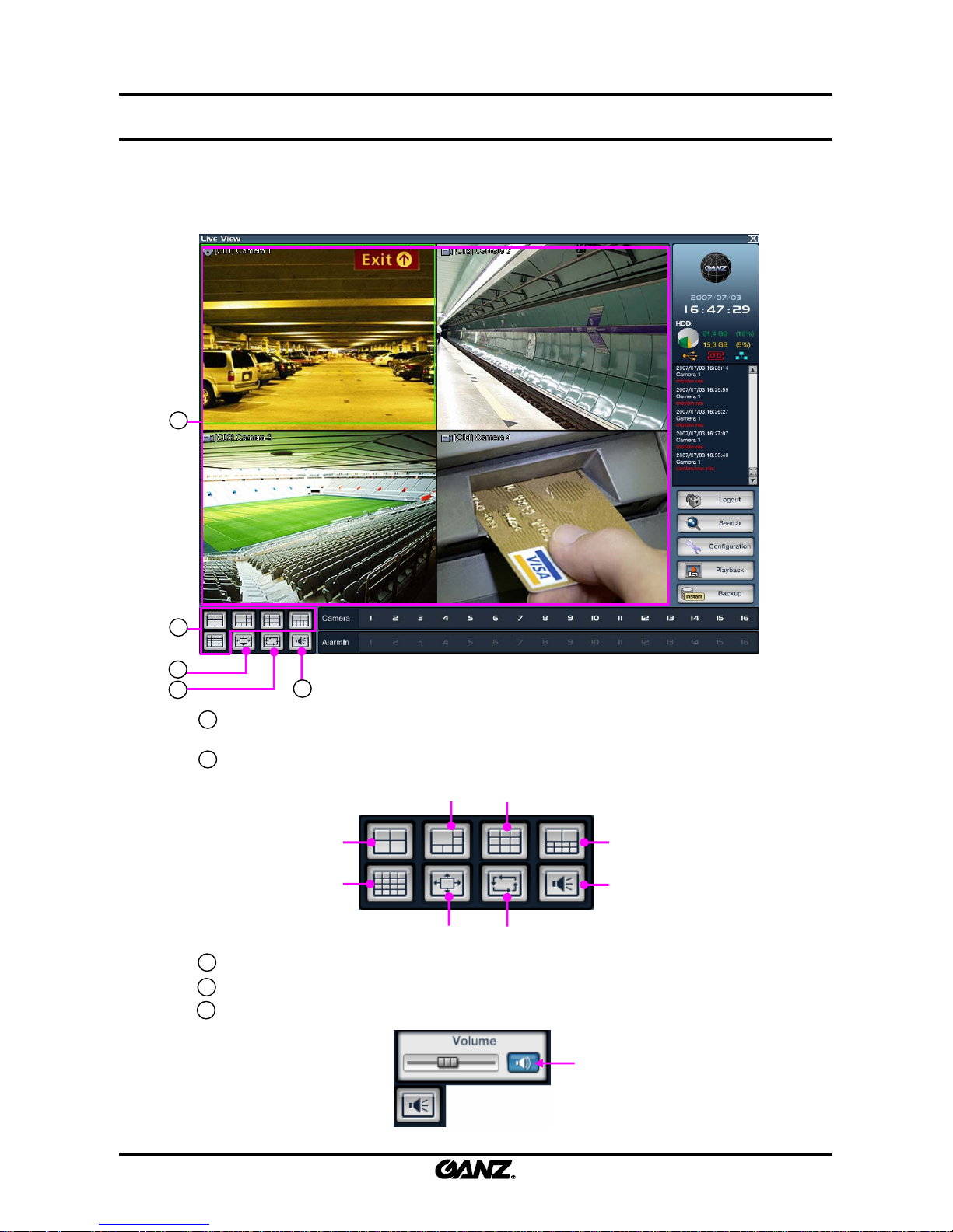
2.1 Live screen
2.1 Live screen
The search picture provides a variety of split and whole screen displays. It can control the PTZ, which is
connected to the selected camera and 1ch instant playback. You can also enter the search and system
setup menus.
☞
☞
The live picture can only be displayed at logon.
The live picture can only be displayed at logon.
1
2
3
4
5
View panel : Displays the live picture and 1ch playback. You can move any camera picture in the
view panel by drag & drop.
Split button: Select 4/6/9/10/16 splits. If you press the 4/6/9/10 split button repeatedly, the
camera picture will rotate in order.
Full Screen button : Expand the view panel to full screen.
Channel rotation : Set the rotation of the split screen (4/6/9/10).
Audio volume control button : Displays the audio volume control.
1
2
3
4
2. Live
Quad
6-way
9-way
10-way
Full screen
Sequence
16-way
Volume
5
Mute
21
21
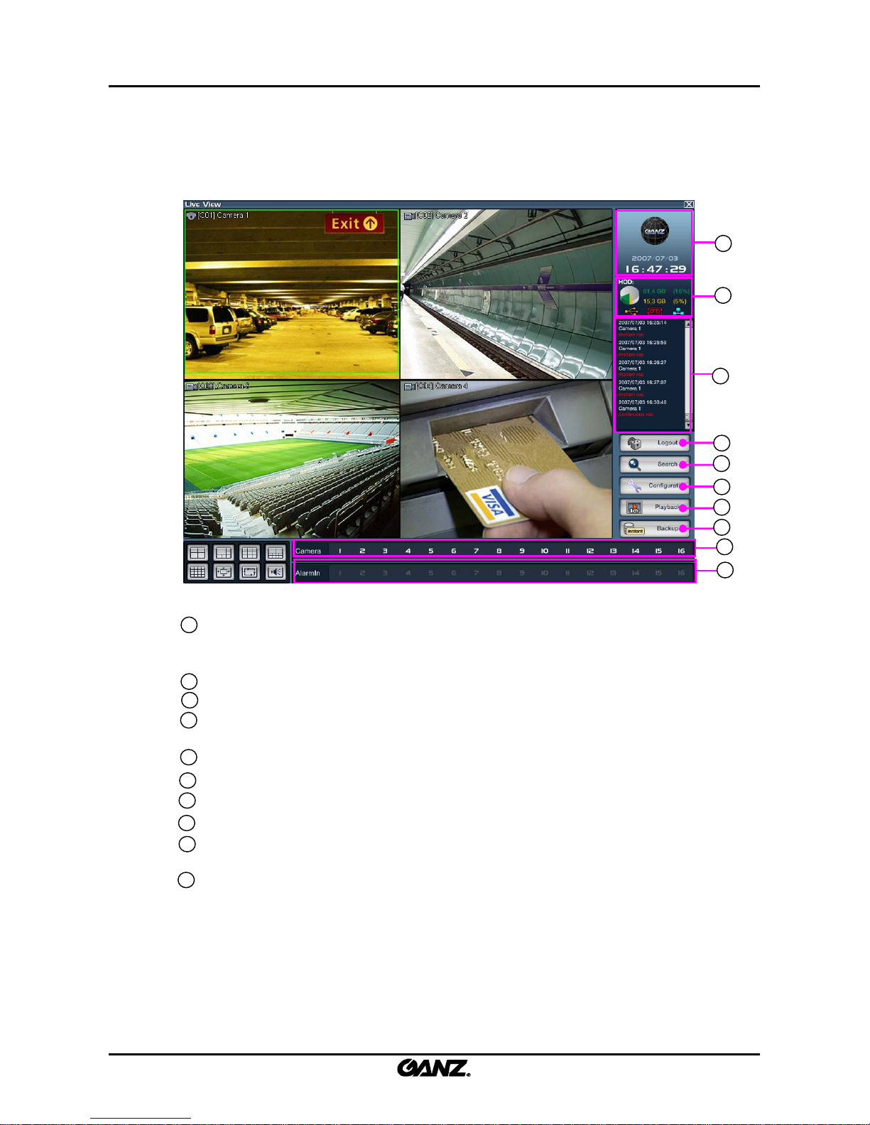
Camera button : Indicates which camera is connected to the DVR. Drag the camera button and
drop it to at the desired location, then that camera picture will be shown on
the selected display area.
Alarm-In : It indicates which sensors are connected to the DVR system.
Time Display : Shows the GANZ logo and the current time and date.
System condition Window : Displays the HDD capacity % used and a light to indicate
the USB/overwrite/network status.
Event window : It displays each event which occurs on the system.
Login : Click this button to access the DVR menus. Click to login and click again to logout.
Search button : Click to enter the search menu.
Configuration button : Click to enter the setup menu.
1Ch Playback button : Play one channel backwards instantly (the time gap of the instant playback
can be set in chapter 3.6.2 Setup – 1Ch Playback Time ).
Instant Backup : Backup a camera instantl y (set back up time in chapter 3.6.2 Setup – Instant
Backup Time).
7
8
9
10
6
10
11
12
13
14
15
11
8
9
6
7
12
13
14
15
22
22
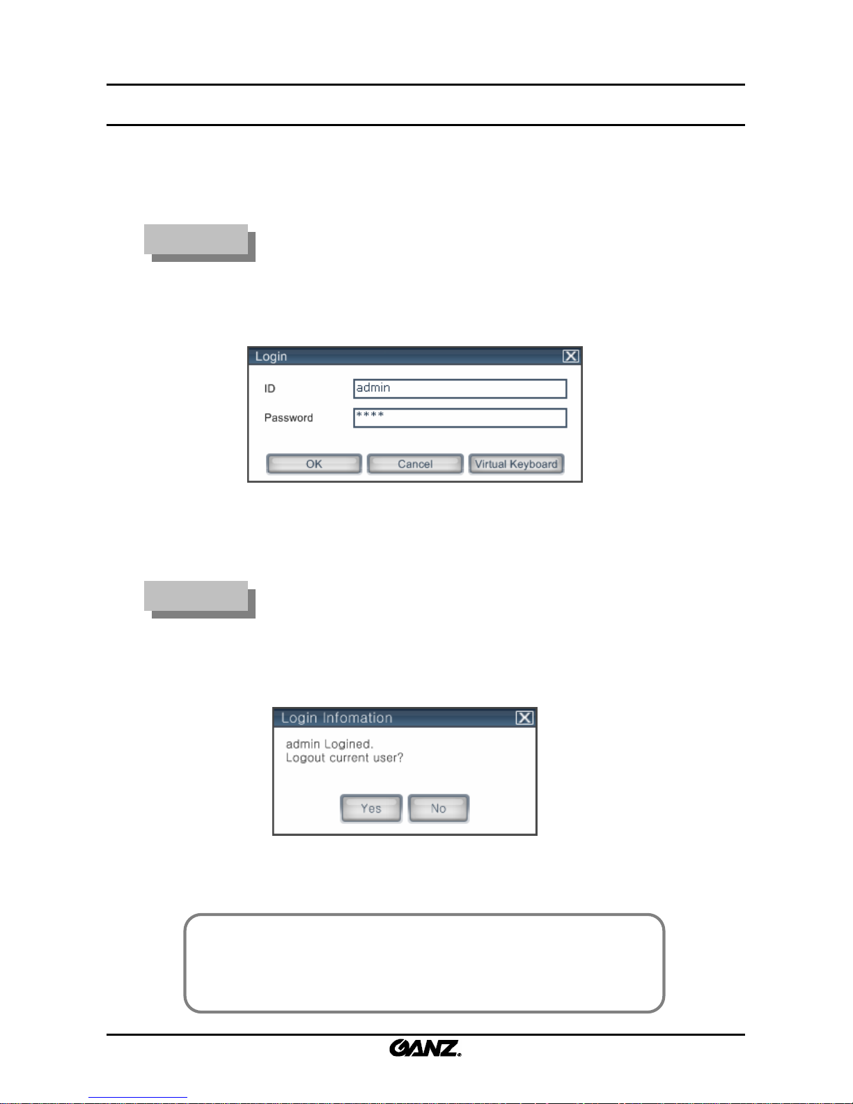
2.2 Login menu
2.2 Login menu
After setting up the user ID and password, you can control the authorization of the other users in the
search and setup menus as well as the availability of other functions.
Login
Login
1. Click on the “Login” button.
2. The login window is displayed.
3. Enter the ID and password and click on the “OK” button.
Logout
Logout
2. The login information and user are displayed.
3. Click on the “Yes” button to log out the current user.
[Note]
• No default password is set up for the administrator.
• It is impossible to change the administrator password once it has been set. For
this reason, please use a memorable password.
☞
☞
1. Click on the “Logout” button.
23
23
2.3 Picture composition
2.3 Picture composition
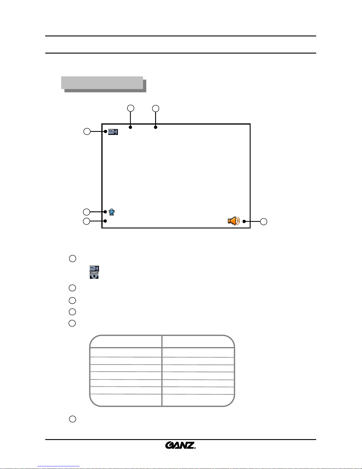
Picture composition
Picture composition
[C01] CAMERA01
REC : M
2
1
3
5
Camera Mark : Display for camera motion and normal or PTZ camera.
: Stands for a normal camera.
: Stands for a PTZ camera.
Camera number : Display for the channel number.
Camera name : Display for the camera name.
MIC Mark : Display for the audio recording of each camera.
Recording : Display for the recording condition of each camera. (see table below)
1
2
3
4
Not recording
Continuous
Motion
Object watch
Alarm In
Pre-alarm
ATM/POS recording
Screen DisplayRecording Type
None
REC : C
REC : M
REC : O
REC : A
REC : P
REC : $
6
Audio output indication : Select one channel full screen for audio playback.
When selected, this icon appears to indicate live audio.
6
4
5
24
24
2.4 System status
2.4 System status
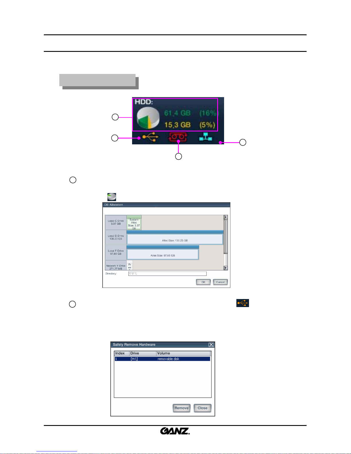
System status
System status
a
c
b
d
Hard disk storage : The size of the hard disk and percentage used are displayed.
HDD usage diagram color will change to red after 90% full.
Click on the icon to enter the Database allocation menu. (As Below)
a
b
USB connectivity : Displays if a USB device is connected. Double click , if you want
to disconnect the USB device from the system. The window below will then appear, click on
the device you want to remove in the list, and then click “Remove” button.
USB device connected : Orange color.
USB device not connected : Gray color.

25
25
Recording process: Displays if the DVR is overwriting on the storage
One-time recording : Gray.
Overwrite recording : Red.
CMS connect : Displays if CMS remote software is connected.
CMS connected : Blue.
CMS not connected : Gray.
c
d
26
26
2.5 DB drive allocation
2.5 DB drive allocation
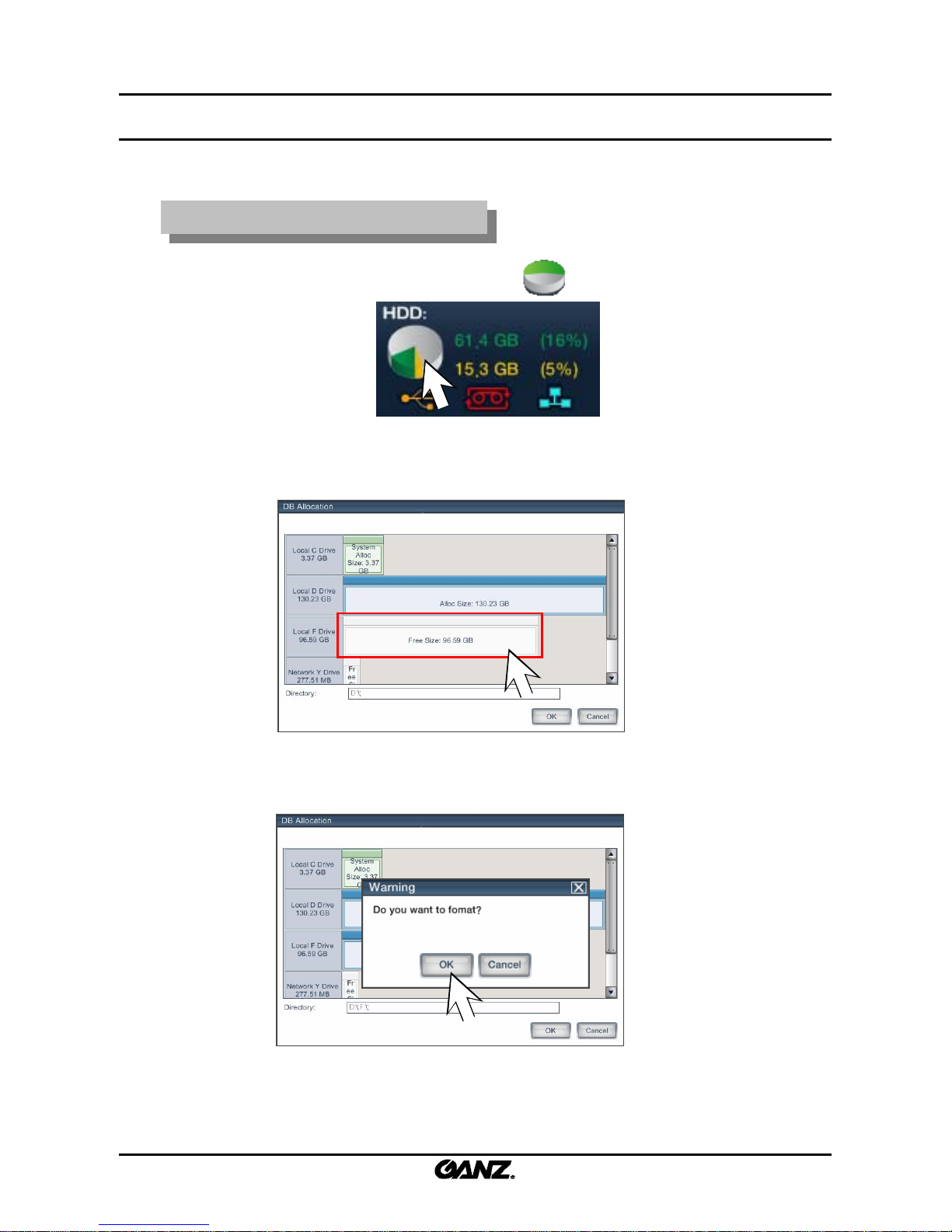
New DB drive allocation
New DB drive allocation
1. Using the administration login, double-click on the icon.
2. The following DB Allocation window will be displayed.
3. When a mouse is left-clicked on “Free Size” as indicated by the red square above, the
following message window will be displayed: “Do you want to format?”. Click on the
“OK” button to allocate the DB drive.

27
27
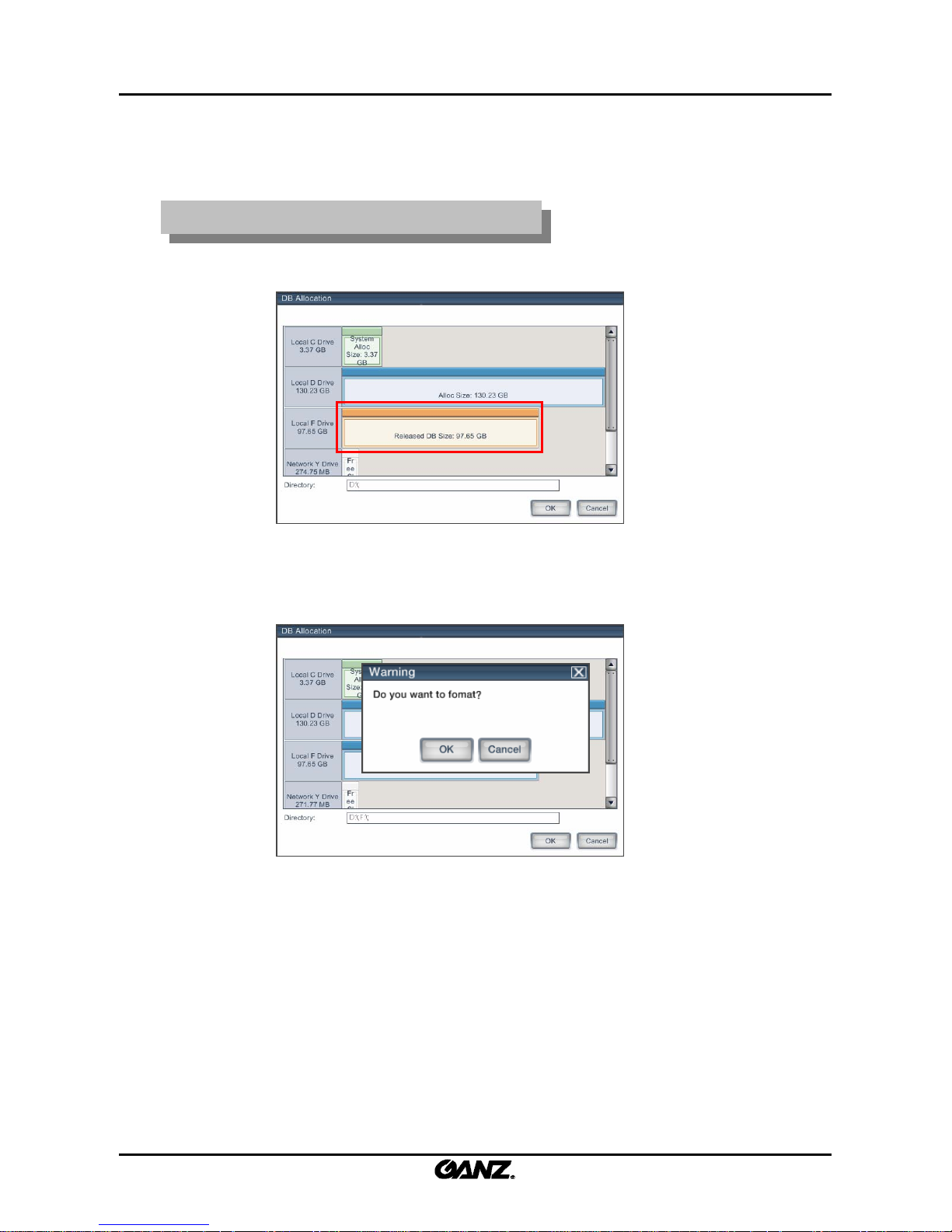
DB drive storage release or free space
DB drive storage release or free space
2. The allocated DB drive is released upon clicking on the “OK” button. The released DB
drive will be shown in orange.
1. In order to remove an allocated DB drive, right-click on the drive as shown below. If the
drive is allocated, this is indicated with a blue color. Once removed, it will change to a
grey color.
3. To change the released DB partition to free status, right-click on the corresponding
partition. (Although the released DB drive contains DB data, the DB data is not
recognized by the system. Once the DB has been released, all data has been cleared).
28
28
Reallocation of released DB drive
Reallocation of released DB drive
1. When a mouse is left-clicked on a released DB drive, the following message window
will be displayed: “Do you want to format?”
2. If the “OK” button is clicked, then the released DB drive is formatted and then allocate d back
to the DB storage structure. If the “Cancel” button is clicked, the DB drive is allocated back
to the DB storage without being formatted.
29
29
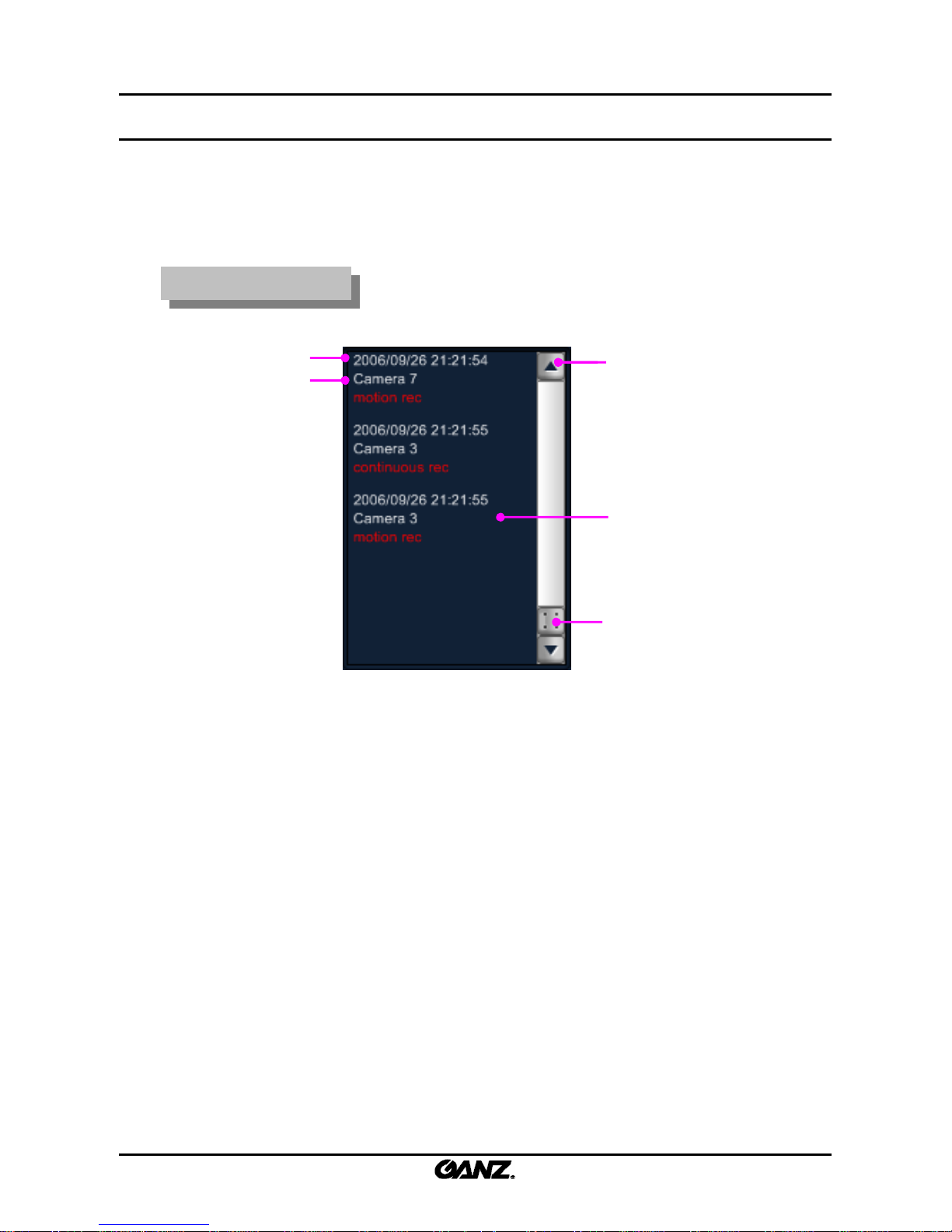
2.6 Event indication
2.6 Event indication
The camera status for continuous, motion, sensor, ATM/POS recording and network connection is
displayed. In the event indication window, the display shows the camera number and the time of event
occurrence.
Event indication
Event indication
Camera number
Time of event occurrence Move upper event
Event contents
Scroll event window
30
30
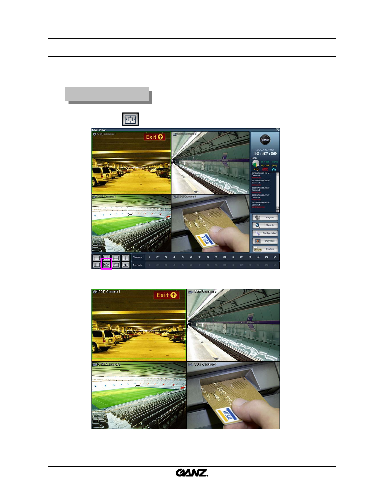
2.7 Full screen display
2.7 Full screen display
Convert to full screen
Convert to full screen
1. Click on the button to expand the view panel.
2. The view panel displayed in full screen is shown below.
3. Right-click to return to the original size.
 Loading...