

Ganz ZR-DH111NP Instruction Manual

Contents
Contents
Introduction
Intended Use 3
Identification Plate 3
Safety Measures
Electrical Hazards 3
Installation 3
Maintenance and Repair 4
Operation 4
Symbols Used in This Manual 4
Product Description
Items Supplied 4
Main Functions in Brief 4
Operating Controls and Display Functions 5
Installation
Recording
Instant Recording 20
Alarm Recording 20
Playback
Normal Playback 21
Search Playback 22
Copy
Still Image Copy 23
Copy to Movie File 23
Interface Specifications
RS232 24
Basic Operation 7
Connections on Back of Unit 8
System Connection
One Camera Connection 10
Multiplexer Connection 10
Quad Connection 11
Programming
Clock/Language Setting Menu 12
Timer Set Setting Menu 13
Normal Record Setting Menu 14
Alarm Record Setting Menu 15
Buzzer Setting Menu 16
Archive Setting Menu 16
Network Setting Menu 17
System Setting Menu 17
Appendix
Remote Control Protocol 25
Remote Controller 25
Time Lapse/FPS Mode Recording Time 26
Security Lock Setting 28
View from Internet/Intranet 28
Main Screen 29
LAN Functional Specification 31
These Installation and Operating Instructions, (edition 03/2003, Ver 1.3) are for use with
One channel digital video recorder (year 2003 model)
2 ZR-DH111NP

Introduction
Introduction
These installation and operating instructions are
designed for the use of anyone concerned with the
setting-up or day use of the unit. All persons involved
in carrying out installation work(i.e. qualified
electricians or service engineers), must ensure that
they are familiar with the unit electrical and electronic
systems and should follow the applicable safety rules
and other relevant legislation all times.
Intended Use
The one channel digital video recorder is the first true
VCR replacement designed particularly for the security
industry, seamlessly combining high-resolution video
multiplexing and digital recording. The Unit can record
at speeds up to 60/50 images per second with NTSC/
PAL formats and replay event instantly. The Unit
incorporates all the benefits of digital video recording,
is simple to install, and operates just like a VCR. The
highly efficient compression technology, as well as the
superior clarity and detail of recorder images, make
the one channel digital video recorder stand out from
its competitors as the best choice for security
surveillance.
Safety Measures
Electrical Hazards
• Refer all work related to the installation of this
product to qualified service personnel or system
installers.
• Do not block the ventilation opening or slots on the
cover.
• Do not drop metallic parts through slots.This could
permanently damage the appliance. Turn the power
off immediately and contact qualified service
personnel for service.
• Do not attempt to disassemble the appliance.To
prevent electric shock, do not remove screws or
covers. There are no user-serviceable parts inside.
Contact qualified service personnel for
maintenance. Handle the appliance with care. Do
not strike or shake, as this may damage the
appliance.
• Do not expose the appliance to water or moisture,
nor try to operate it in wet areas. Do take immediate
action if the appliance becomes wet. Turn the power
off and refer servicing to qualified service personnel.
Moisture may damage the appliance and also cause
electric shock.
Identification Plate
Precise identification of each device is provided by
the plate fixed to the rear of the unit, which shows its
model designation and serial number. Please copy
these details into the box below. This will ensure that
you have the required data to hand if a query arises or
whenever you need to order spares.
Model:
Serial number:
• Do not use strong or abrasive detergents when
cleaning the appliance body. Use a dry cloth to clean
the appliance when it is dirty. When the dirt is hard
to remove, use a mild detergent and wipe gently.
• Do not overload outlets and extension cords as this
may result in a risk of fire or electric shock.
• Do not operate the appliance beyond its specified
temperature, humidity or power source ratings. Do
not use the appliance in an extreme environment
where high temperature or high humidity exists. Use
the appliance at temperature within 0°C ~ +50°C
and a humidity below 90%. The input power source
for this appliance is AC90~265V.
Installation
• The installation tasks described in this manual are
to be carried out by adequately trained electrical
technicians only, who should ensure that relevant
electrical standards and legislation are observed at
all times.
• Any modifications to the unit are likewise the
exclusive preserve of trained electrical specialists.
ZR-DH111NP 3
Safety Measures
Product Description
Maintenance and Repair
• All maintenance and repair operations should be
carried out by trained electrical specialists.
• Unauthorised repairs can lead to personal injury,
material damage or harm to the unit itself.
Operation
• Operate this unit strictly according to the instructions
contained in this manual.
• Unauthorised operation can lead to personal injury,
material damage or harm to the unit.
Symbols Used in This Manual
The safety instructions given in this manual are
classified into two groups:
DANGER of electric shock
Failure to observe safety warnings identified with
this symbol can lead to electric shock injuries. The
symbol is used to identify immediate hazards.
Items Supplied
1 one channel digital video recorder
1 Installation and operating instructions
1 CF card reader
1 Power Cord
Main Functions in Brief
• Digital Recording provides superior quality images
•Pre-Alarm image recording
• Compatible with most multiplexers
•Time lapse and real time recording
• Refresh rate up to 60 field (50 field for PAL)
• Quick Search by date/time, alarm events, and
recording list
• Fast and slow playback of recorded video in various
speeds
• On-screen setup menu and system timer
Caution
This symbol identifies hazards likely to cause harm
to the unit itself or other material damage.
You will also find instructions designed to simplify the
operation of the unit:
Note
This symbol is used to identify special operating
features of the unit.
The CE Marking is a Directive Conformity mark
of the European Union (EU).
This device complies with Part 15 of the FCC Rules.
Operation is subject to the following two conditions:
(1) This device may not cause harmful interference,
and (2) This device must accept any interference
received, including interference that may cause
undesired operation.
• Multi-level password protection
• RS-232 communication port
• Highly stable Non-PC based proprietary system
• Built-in M-JPEG compression/decompression with
configurable quality
• Audio recording capability
•Programmed with various time-lapse speeds, Data
can be stored in Compact Flash Card.
• Operation status record log
4 ZR-DH111NP
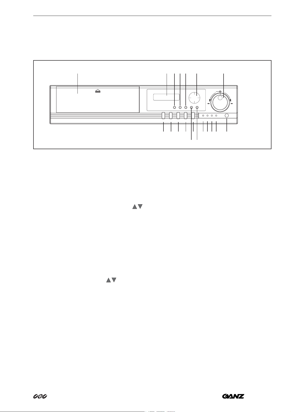
Operating Controls and Display Functions
Front panel
Product Description
10
1PAUSE
Press this key to pause the playback picture.
2 REV. PLAY
Reverse Play Back. The playback speed is
shown on the LCD display, and press
change the speed if necessary.
11 12 13 14 16 18
SHUTTLEJOG
REV FF
SEARCH
COPY
Display MENU
ENTER
HDD
LAN
PAUSE
REV/PLAY
STOP PLAY REC
5
ALARM POWER
67891234
19
15 17
6 HDD
HDD Access, the LED will lit when HDD is
accessed.
7 LAN
to
LAN Access, the LED will lit when LAN is
accessed.
3STOP
Press this key to stop Recording and
Playing Back.
4 PLAY
Playing Back. The playback speed is shown on
the LCD display, and press
to change the
speed if necessary.
5 REC
Press this key to start recording.
8 ALARM
The LED will lit when alarm occurs.
9 POWER
Indicate the power is normal.
10 Hard Disk Tray and Compact Flash Card
Slot
Hard Disk holder for HDD and Insert a Compact
Flash Card.
ZR-DH111NP 5

Product Description
11 LCD Display
2002/04/24 SYSLD
12:00:00 002 HR
Switch on the power, “system loading” will be
shown 10 seconds, both in LCD display & Main
monitor.
2002/04/24 STD
12:00:00 002 HR
In Standby mode, the date/time is current date/
time and the right part shows the quality and rate
setting for normal recording.
2002/04/24 REC
12:00:00 . 002 HR
In Recording mode, the date/time is current date/
time and the right part shows RECORD and
current recording rate.
2002/04/24 PLAY
12:00:00 > 002 HR
In Playback mode, the date/time is the playback
date/time and the right part shows PLAYBACK
and current playback rate.
12 SEARCH
Press this key to enter the Search Playback
Menu.
15 MENU
Press this key to enter Setup menu.
16 Up/ Down
(1) In Menu mode, press those keys to change
data.
(2) In Record/Playback mode, press those keys
to change the Record/Playback speed.
Left/ Right
In Menu mode, those keys are used to move
cursor.
17 ENTER
Press this key to confirm the selection or data
changed.
18 Shuttle Dial
In Playback mode, turn shuttle dial can fast
forward/rewind the picture.
In Pause mode, turn shuttle dial can slow
forwards/rewind the picture.
In Menu mode, turn shuttle dial can change menu
page forwards/rewind.
Jog Dial
In Pause mode, turn the jog dial can forwards/
rewind the Picture by one field.
In Menu mode turn the jog dial clockwise, for
increase the cursor data which show on the
system. Turn the jog dial counterclockwise, for
decrease the cursor data which show on the
system.
13 COPY
Press this key to start copy still picture or video
stream into Compact Flash card.
14 Display
Press this key to switch ON/OFF the display.
19 Remote Control
IR Remote receiver
6 ZR-DH111NP

Installation
Basic Operation
Installation
1Insert a HDD (IDE) for Video Storage
The HDD should be set as MASTER.
(Normally the default setting of HDD is Master)
Note
After hard disk case is inserted into the hard
disk tray, be sure to turn the tray key in lock
position. Otherwise, hard disk will not be
detected and The System Loading procedure
can not be completed.
2 Connect cable for video/audio input and
video/audio out
The POWER LED lights if power is normal.
3Switch Power On
The detail connection is described in SYSTEM
CONNECTION.
4Press MENU key to enter SET UP MENU.
Once inside the main menu you will find there are
nine set up pages as below:
1. CLOCK/LANGUAGE SETTING MENU
2. TIMER-SET 1 SETTING MENU
3. TIMER-SET 2 SETTING MENU
4. NORMAL RECORD SETTING MENU
5. ALARM RECORD SETTING MENU
6. BUZZER SETTING MENU
7. ARCHIVE SETTING MENU
8. NETWORK SETTING MENU
9. SYSTEM SETTING MENU
5Turn the shutter dial clockwise or
counterclockwise to change set up page.
ZR-DH111NP 7
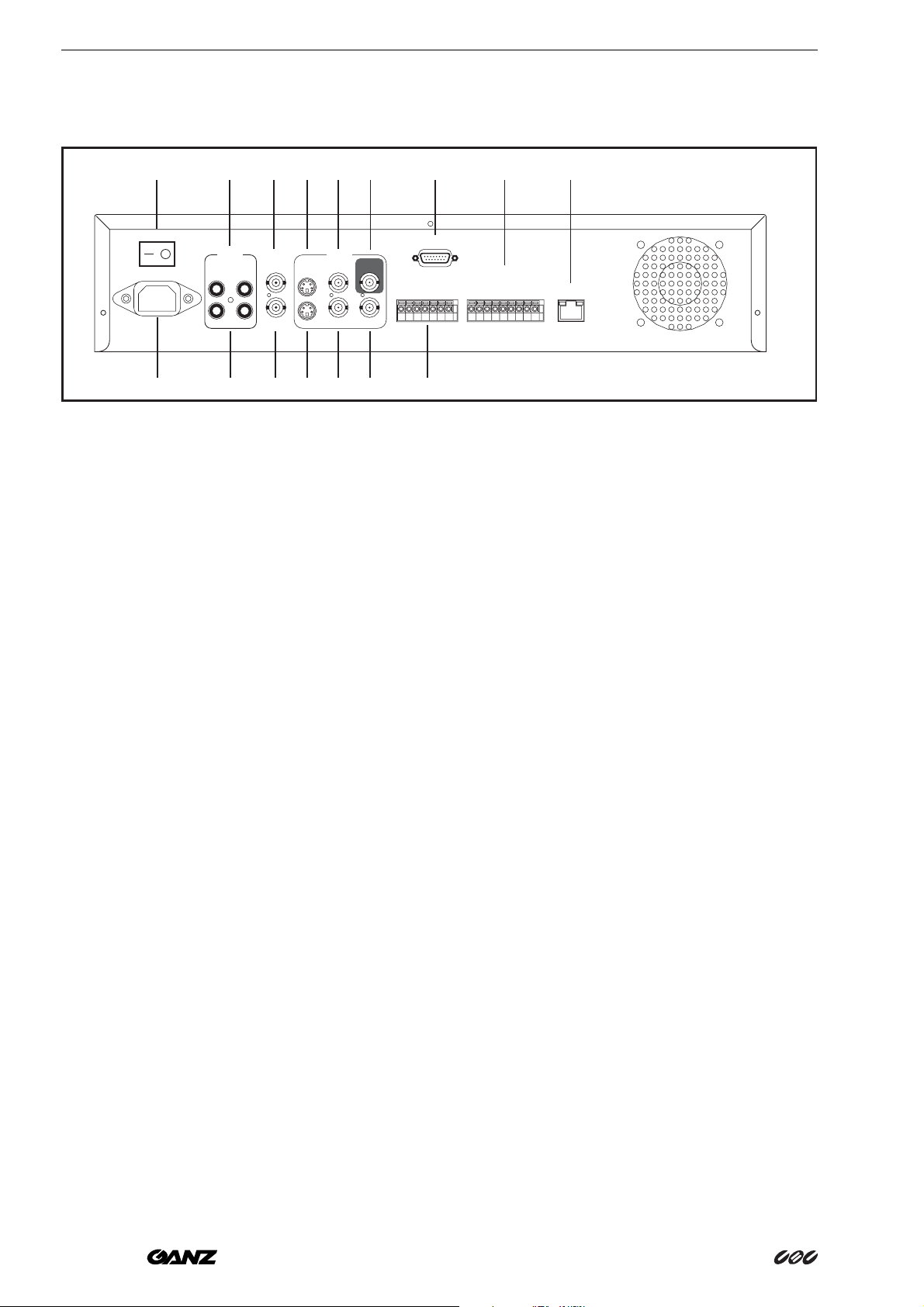
Installation
Connections on Back of Unit
1
POWER
AC 90-260 V
2
OFF
3
MUX MAIN
AUDIO
MONITOR IN
12
IN
OUT
MONITOR OUT
4
57812 15
691011 13
1 Power Switch
To switch ON/OFF the main power.
2 Main Power plug
The main power input.
VIDEO
S-VIDEOININ
12
OUT OUT
LOOPING
OUT
GND
ALM-IN
RS232
ALM-RST
REC
NC2
GND
NC1
6 MONITOR
7 S-VIDEO IN
14 16
GND
ALM-NC
ALM-NOT
ALM-COM
SW OUT
DISK FULL
LAN
NC3
NC4
GND
Video output BNC connector connected to main
monitor.
The S-VIDEO input connector.
3 Audio IN 1, 2
Audio input for recording.
4 Audio OUT 1, 2
These two audio outputs can be set enable or
disable in Setup Menu.
5 MUX MAIN MONITOR
Video input BNC connector, connected to multiplexer main monitor output.
8 VIDEO IN
The composite video input connector.
9 S-VIDEO OUT
The S-VIDEO output connector.
10 VIDEO OUT(1)
The composite video output connector.
8 ZR-DH111NP

Installation
11 VIDEO OUT(2)
Augment composite video output connector.
12 VIDEO LOOPING
The loop-through composite video output, could
be connected to other devices.
13 Alarm Input Terminal Block
ALM-IN
Normal Open or Normal Close type alarm sensor input.The Alarm Input can be selected as
Normal Open or Normal Close input in the setup
menu.
When an alarm occurs, alarm recording will automatically start.
ALM-RST
Normal Open or Normal Close type alarm reset
input to reset the alarm.
ALM-NO
Normal Open Alarm output. In normal condition,
this terminal is open from the terminal of ALMCOM.
In alarm status, those two terminals are shorted.
ALM-COM
Alarm Common Contact.
SW OUT
Step signal to synchronize the machine and multiplexer.
DISKFULL
Disk-Full alarm signal.
15 RS232 connector
Connect D-Sub 9 pins connector to RS232 ports
for remote control.
REC
External Recording request signal. The machine
will start recording when a High Level is applied
on this input terminal. If the machine is not in the
timer, recording mode, the machine will stop recording when the REC signal drops from High to
Low level.
14 Alarm Output Terminal Block
ALM-NC
Normal Close Alarm output. In normal condition,
this terminal is shorted to the terminal of ALMCOM.
In alarm status, it is open between ALM-NC and
ALM-COM terminals.
16 LAN Connector
Connect to the RJ-45 LAN connector.
ZR-DH111NP 9
System Connection
System Connection
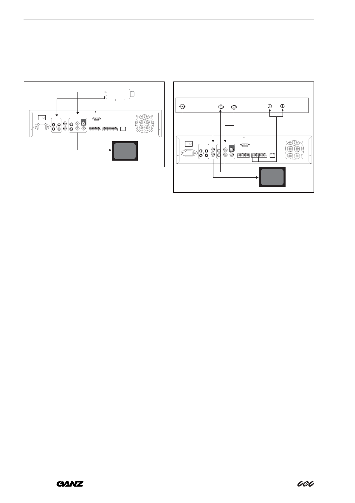
One Camera Connection
1
2
POWER
OFFON
MUX MAIN
AC 90-260 V
AUDIO
12
IN
OUT
MONITOR IN
MONITOR OUT
S-VIDEOININ
OUT OUT
VIDEO
1Video or S -VIDEO out
When the camera output is composite, connect
to the video input BNC connector.
The video input setting should be set as COMPOSITE. (SYSTEM SETTING MENU)
When the camera output is S-VIDEO, connect
to the S-VIDEO input.
LOOPING
OUT
12
RS232
GND
ALM-IN
ALM-RST
REC
NC2
GND
NC1
LAN
GND
ALM-NC
ALM-NOT
ALM-COM
DISK FULL
NC3
NC4
GND
SW OUT
3
Main Monitor
Multiplexer Connection
Multiplexer
NC1
NC2
GND
GND
ALM-NC
ALM-NOT
ALM-COM
DISK FULL
SW OUT
STEP Signal GND
4
LAN
NC3
NC4
GND
Main Monitor
VCR IN VCR OUTMAIN MONITOR OUTPUT
POWER
AC 90-260 V
OFFON
3
AUDIO
12
IN
OUT
MUX MAIN
MONITOR IN
MONITOR OUT
2
S-VIDEOININ
OUT OUT
1
VIDEO
LOOPING
OUT
12
RS232
GND
ALM-IN
ALM-RST
REC
5
1 Multiplexer VCR Out
Connected to the VIDEO IN connector at the rear
panel.
The video input setting should be set as S-VIDEO.
(SYSTEM SETTING MENU)
2 Audio Out
The camera audio output is connected to the
audio input terminal at the rear panel.
3 System Main Monitor Output
The main monitor is connected to the VIDEO OUT
1 BNC connector or S-video output S-connector.
4 Please set the Multiplexer item to OFF .
(NORMAL RECORD SETTING MENU)
2 Multiplexer VCR In
Connected to the VIDEO OUT 1 connector at the
rear panel.
3 Multiplexer Main Monitor Output
Connected to the MUX. MAIN MONITOR IN connector at the rear panel.
4 Step Signal
This signal is used to synchronize the multiplexer
and the video recorder.
5 System Main Monitor Out
Connect the MAIN MONITOR OUTPUT connector to the main monitor.
6 Please set the Multiplexer item to ON .
(NORMAL RECORD SETTING MENU)
10 ZR-DH111NP
 Loading...