

Ganz ZNT1-HET14G29A, ZNT1-HET14G25A, ZNT1-HBT24G35A, ZNT1-HET14G20A, ZNT1-HBT24G22A Quick Start Guide
...
CBC AMERICAS CORP. - EAST COAST +1 (919) 230-8700 | WEST COAST +1 (310) 222-8600 | MEXICO +52 (55) 5280 4660
ganzsecurity.com. 01/17
1
ZNT1-H Series Quick Start Guide
Before installing and operating the unit, please read this manual
thoroughly and keep it for future reference.
About the manuals
This manual provides the instructions for the quick installation
and the basic configuration of your IP device. For more detailed
information, refer to the camera’s installation guide and the web
page user’s manual.
Part names and functions
Please check the name and position of each part by
referring to the following image.
Sunshield: It prevents the lens from getting the direct sunlight.
NTSC / PAL Button: The button switches the video output mode between
NTSC and PAL. Pressing the button will maintain the current video output
mode unless pressing again to switch to the other mode.
Analogue Video Output: Connect a video output cable to see video via an
analogue monitor.
RJ45 Socket: RJ45 LAN connector for 10/100 Base-T Ethernet (PoE supported)
Reset Button: Press the button either for the restart or the factory default
of the device. For restart, 1.press the button only for 2 seconds while the
device is powered on. 2.Wait for the system to reboot. For factory default,
1.
press the button for 10 seconds while the device is powered on. 2.Wait for
the system to reboot. There are also the methods performed on the
camera’s web page. Refer to the Reboot and Factory Default section in this
manual.
Terminal Connectors for DI/DO: Connector for audio input (sensor) and
audio outputs (alarms). Refer to the Connection section for more
information about the characteristics of DIDO in the installation guide.
Terminal Connectors for Audio I/O: Connector for audio input (MIC) and
audio output(speaker). Refer to the Connection section for more
information about the characteristics of audio in the installation guide.
Terminal Connectors for RS-485: Connector for RS-485. Refer to the
Connection section for more information about the characteristics about RS485 in the installation guide.
Terminal Connector for power adaptor: Connector for power supply
(12VDC, 24VAC, and PoE supported).
Installation
Installing Cable Gland
To meet the IP66 requirements, you need to install the cable gland unit to
the camera. Follow the instructions on the other side of this page.
Connecting Cable(s)
Refer to the connection section for more information about each connector.
Installing Base Mount
Connecting Cables
For the information about the necessary cables, refer to the part names and
functions section on the left side of this page and the Connection section in
the installation guide.
Closing Back Cover
Installing Sunshield
Terminal
connectors
for power
adaptor
Sunshield
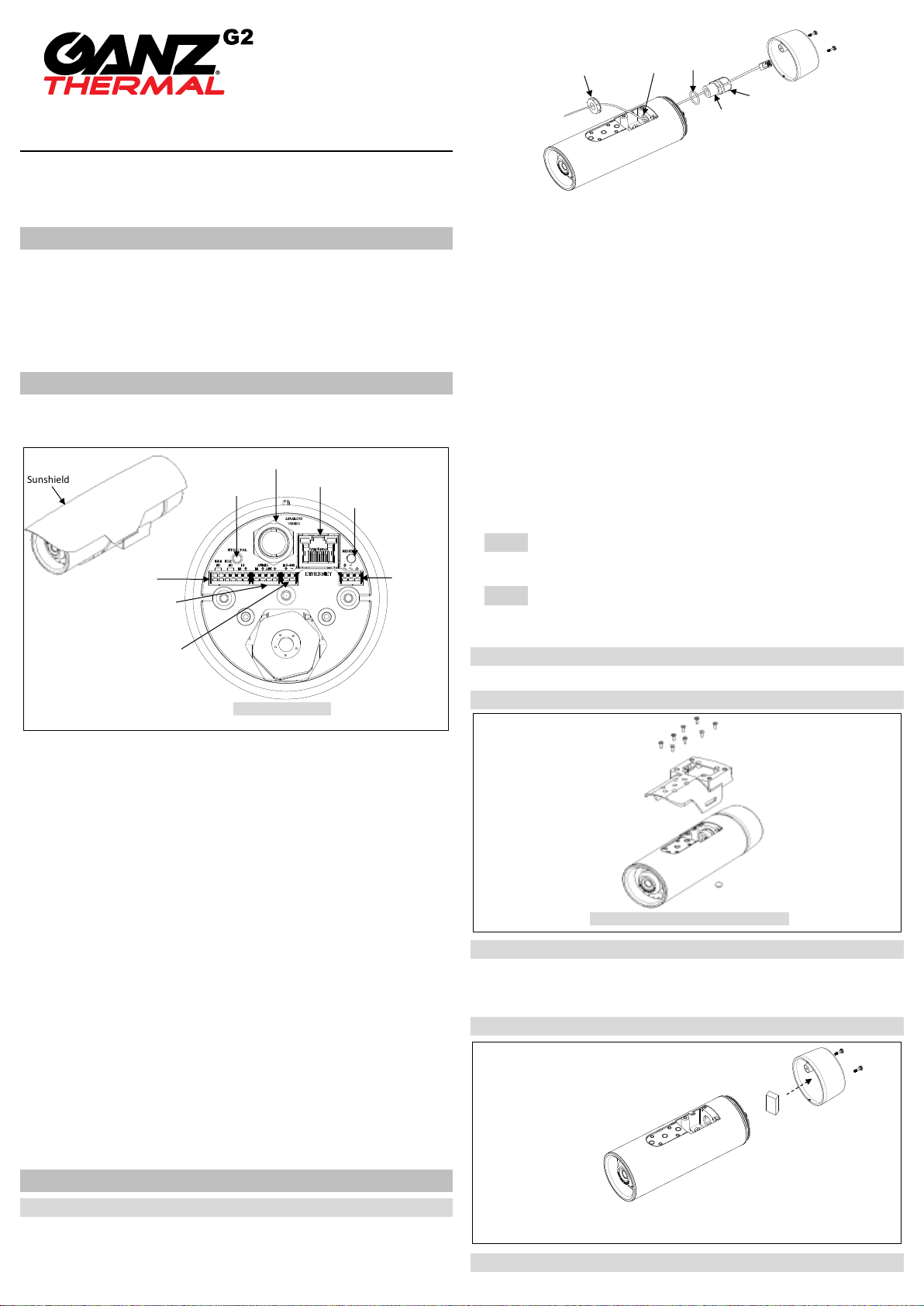
1) Detach the back cover by twisting it counter-clockwise.
2) Disassemble the cable gland unit
(Disassembled parts: electrical nut, rubber sealing
ring inside the gland - you need to take it out, gland body, and sealing nut).
3) Pass the electrical nut through the ends of the necessary cables.
4) Pass the cables through the holes both on the back and the bottom of
the camera by referring to the image above.
5) Pass the provided O-ring, gland body through the ends of the cables
that are on the backside of the camera.
6) Insert the cables into the rubber sealing ring at the point where about
4.5 inches (11.5 cm) of the cable ends remains to connect to the
corresponding connectors on the back panel later.
7) Push the rubber sealing ring through the claw of the gland body.
8) Insert the sealing nut into the thread of the gland body, and tighten it
by turning the nut on the thread. The rubber sealing ring will be tightened
to fill the gap between the rubber sealing ring and the cables.
9) Push the gland unit through the hole on the back of the camera so that
the other end of the thread on the gland unit will be inserted into hole for
gland.
10) Fix the gland unit to the hole by inserting the electrical nut and
tightening it on the thread of the gland unit.
NOTE1
A thin type of the BNC cable is recommended when you insert
multiple cables including a BNC cable as the standard size of BNC cable is
too thick to be inserted together into the rubber sealing ring.
NOTE2
Use the detachable cable with a separate BNC connector to pass
the hole of the sealing nut or the female type head of the BNC cable to
pass the hole of the sealing nut.
1) Insert the provided
8 tamper resistant
screws to the
corresponding screw
holes on the base
mount by referring to
the image on the right.
2) Tighten them with
a Phillips head #2
screwdriver to fix the
base mount to the
camera.
1) Insert the provided
silica gel packet inside
the back panel.
2) Close the back
panel of the camera
by twisting the back
cover clockwise
on the camera’s back
panel.
3) Insert the two tamper
resistant screws into the
holes on the back cover,
and tighten them with a
Phillips #2 screwdriver
to fix the back cover to
the camera unit.
* The model herein and its appearance are subject to change without any prior notice.
NTSC / PAL button
Analogue video output
RJ45 socket
Reset button
Terminal connectors
for DI/DO
Terminal connectors
for Audio In/Out
Terminal connectors
for RS-485
[ Back Panel of Camera ]
Electrical nut
Hole for gland
O-ring
Gland body
Sealing nut
[Base Mount Installation: Upside-Down View]
CBC AMERICAS CORP. - EAST COAST +1 (919) 230-8700 | WEST COAST +1 (310) 222-8600 | MEXICO +52 (55) 5280 4660
ganzsecurity.com. 01/17
2
Installing with Bracket/Adaptor
There are currently 7 optional accessories such as wall mount bracket,
corner mount bracket, and so on. Please refer to the corresponding
accessory’s installation guide for the installation instructions.
Setting up network environment
The default IP address of the device is 192.168.XXX.XXX. Users can identify
the IP address of the device by converting the MAC address’s hexadecimal
numbers. The MAC address is at the bottom of the device. Be sure that the
device and the PC are on the same network area before the installation.
Generic IP Environment
Convert the device’s MAC address to the IP address. Refer to the
Hexadecimal-Decimal Conversion Table at the end of this manual.
IPAdminTool
IPAdminTool is a management tool to automatically scan all the network
products for the devices’ administrative tasks, which include network
configurations, firmware update, device reboot, factory default, and device
organization.
To modify the device’s default IP address for a customized network area;
1) Find the device from IPAdminTool’s list, and highlight the device’s name.
2) Right-click the mouse, and select IP Address, and select either Single or
Multiple depending on the selected number of devices.
3) Type the new network information including IP Address. The image above
shows the Single IP Change window only. Refer to the manual for
IPAdminTool in case you need the instructions to change multiple IP
addresses.
4) Enter ID and PW(if the device’s ID and PW have never been changed,
check the checkbox of ‘Use default ID/PW’.)
5) Click Apply.
Viewing video on web page
Once the device’s IP address has been identified, type the URL in a web
browser to access the camera. At the first time access, the installation
window like below may pop up.
1) When the browser asks to install the AxUMF software, click Install to
proceed.
2) When the Setup installation pop-up window appears, click Install to
preceed with the rest of the installation.
SETUP page
To setup the device configuraiton:
1) Click Setup on the upper left corner of the web page.
2) Enter the user name and the password when the login page is displayed.
(The default user name and the password are root and pass.)
3) Click OK.
To learn how to set up the camera on the web page for the advanced
configurations, refer to the web page user’s manual.
Reboot*
You can reboot the device via the camera’s webpage, too.
1) Go to Setup > Maintenance > Reboot.
2) Click Reboot to reboot the device.
Factory Default*
You can initialize the current settings to the factory default values via the
camera’s webpage, too.
1) Go to Setup > Maintenance > Reset All Settings.
2) Select the items that you want to keep from the initialization among
network settings, user account information, and time zone setting.
3) Click Reset All Settings.
Safe mode
Your device will get restarted in safe mode if the device does not completely
boot certain times. The main causes for safe mode are as follows.
* The power supply is continually unplugged certain times in the middle of system
booting.
* The firmware files required for system booting are damaged.
* There are conflicts in the system settings.
You will see the page to indicate that your device is in safe mode and to
guide you what to do in steps. Follow the instructions on the webpage
according to each step.
NOTE
One of the methods to update firmware is using IPAdminTool. Please refer
to the manaul for IPAdminTool for the detailed procedure.
NOTE
If your device is still in safe mode after trying to update firmware, please
contact your local agency to get further assistance.
Hexadecimal-decimal conversion table
Refer to the following table when converting the MAC address of your device
to IP address.
Hex
Dec Hex
Dec Hex
Dec Hex
Dec Hex
Dec Hex
Dec Hex
Dec
0
0 25
37 4A
74 6F
111 94
148 B9
185 DE
222
1
1 26
38 4B
75 70
112 95
149 BA
186 DF
223
2
2 27
39 4C
76 71
113 96
150 BB
187 E0
224
3
3 28
40 4D
77 72
114 97
151 BC
188 E1
225
4
4 29
41 4E
78 73
115 98
152 BD
189 E2
226
5
5 2A
42 4F
79 74
116 99
153 BE
190 E3
227
6
6 2B
43 50
80 75
117 9A
154 BF
191 E4
228
7
7 2C
44 51
81 76
118 9B
155 C0
192 E5
229
8
8 2D
45 52
82 77
119 9C
156 C1
193 E6
230
9
9 2E
46 53
83 78
120 9D
157 C2
194 E7
231
0A
10 2F
47 54
84 79
121 9E
158 C3
195 E8
232
0B
11 30
48 55
85 7A
122 9F
159 C4
196 E9
233
0C
12 31
49 56
86 7B
123 A0
160 C5
197 EA
234
0D
13 32
50 57
87 7C
124 A1
161 C6
198 EB
235
0E
14 33
51 58
88 7D
125 A2
162 C7
199 EC
236
0F
15 34
52 59
89 7E
126 A3
163 C8
200 ED
237
10
16 35
53 5A
90 7F
127 A4
164 C9
201 EE
238
11
17 36
54 5B
91 80
128 A5
165 CA
202 EF
239
12
18 37
55 5C
92 81
129 A6
166 CB
203 F0
240
13
19 38
56 5D
93 82
130 A7
167 CC
204 F1
241
14
20 39
57 5E
94 83
131 A8
168 CD
205 F2
242
15
21 3A
58 5F
95 84
132 A9
169 CE
206 F3
243
16
22 3B
59 60
96 85
133 AA
170 CF
207 F4
244
17
23 3C
60 61
97 86
134 AB
171 D0
208 F5
245
18
24 3D
61 62
98 87
135 AC
172 D1
209 F6
246
19
25 3E
62 63
99 88
136 AD
173 D2
210 F7
247
1A
26 3F
63 64
100 89
137 AE
174 D3
211 F8
248
1B
27 40
64 65
101 8A
138 AF
175 D4
212 F9
249
1C
28 41
65 66
102 8B
139 B0
176 D5
213 FA
250
1D
29 42
66 67
103 8C
140 B1
177 D6
214 FB
251
1E
30 43
67 68
104 8D
141 B2
178 D7
215 FC
252
1F
31 44
68 69
105 8E
142 B3
179 D8
216 FD
253
20
32 45
69 6A
106 8F
143 B4
180 D9
217 FE
254
21
33 46
70 6B
107 90
144 B5
181 DA
218 FF
255
22
34 47
71 6C
108 91
145 B6
182 DB
219
23
35 48
72 6D
109 92
146 B7
183 DC
220
24
36 49
73 6E
110 93
147 B8
184 DD
221
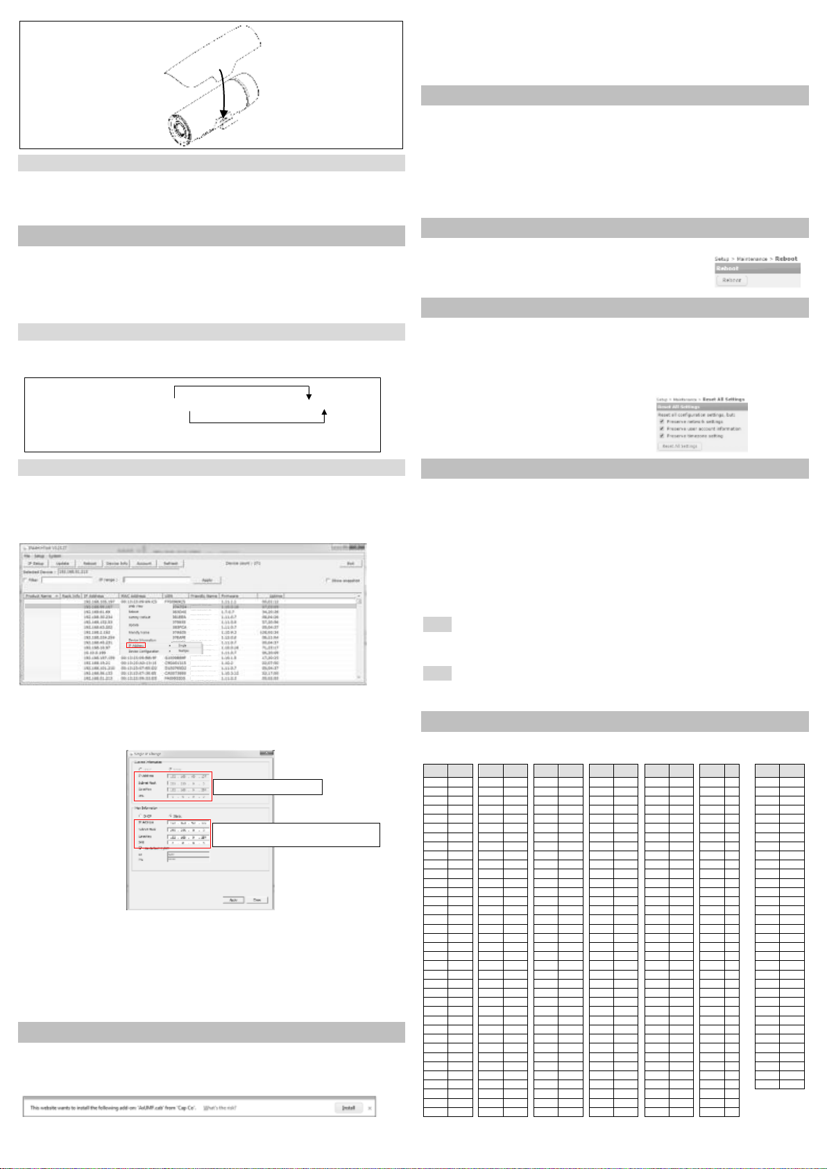
1) Insert the two provided
stem bumpers to the holes
at the bottom of the
sunshield.
2) Place the sunshield on
top of the camera body,
and, snap the sunshield
to the base mount.
MAC address = 00-13-23-01-14-B1 -> IP address = 192.168.20.177
Convert the last two sets of hexadecimal numbers to decimal numbers.
1 CH Encoder
1 CH Encoder
1 CH Encoder
1 CH Encoder
1 CH Encoder
1 CH Encoder
1 CH Encoder
1 CH Encoder
1 CH Encoder
1 CH Encoder
1 CH Encoder
1 CH Encoder
1 CH Encoder
1 CH Encoder
1 CH Encoder
1 CH Encoder
Encoder1
Encoder2
Encoder3
Encoder4
Encoder5
Encoder6
Encoder7
Encoder8
Encoder9
Encoder10
Encoder11
Encoder12
Encoder13
Encoder14
Encoder15
Encoder16
Current PC environment Info
Give a new uniqu e IP address in the last two sets
and mirror other information in the other boxes.
*How to reboot on the device is found in the part names and functions section on the previous page.
*How to do factory default on the device is found
in the Part names and functions section on the previous page.
 Loading...