

Ganz Digimaster DR4N, Digimaster DR8N, Digimaster DR16N, Digimaster DR4N-CD, Digimaster DR8N-CD Instruction Manual
...
1

Specification & Organization -------------------------------------------------- 5
Specifications --------------------------------------------------------- 5
Product Contents List --------------------------------------------------- 7
System Organization ---------------------------------------------------- 8
Product Description -------------------------------------------------------- 9
Front Panel Description (8 & 16ch) ------------------------------------------ 9
Rear Panel Description (8 & 16ch) ------------------------------------------ 10
Front Panel Description (4ch) ------------------------------------------ 11
Rear Panel Description (4ch) ------------------------------------------ 12
Remote Controller Description --------------------------------------------- 13
Connect & Power On ------------------------------------------------------- 14
Live Display Configure ------------------------------------------------------ 15
Division Screen ------------------------------------------------------- 15
Live Display Edit Mode -------------------------------------------------- 16
Digital Zoom --------------------------------------------------------- 17
Sequence ------------------------------------------------------------ 18
Panic Recording ------------------------------------------------------- 18
Key Lock Function ----------------------------------------------------- 19
PTZ Camera Control ---------------------------------------------------- 19
SYSTEM SETUP ----------------------------------------------------------- 21
Display -------------------------------------------------------------- 22
OSD ----------------------------------------------------------- 22
Monitor --------------------------------------------------------- 23
Sequence ------------------------------------------------------- 24
Spot Out -------------------------------------------------------- 28
Camera -------------------------------------------------------------- 30
Camera Title ------------------------------------------------------ 30
Color Setup ------------------------------------------------------ 31
PTZ Setup ------------------------------------------------------- 32
Motion Sensor ---------------------------------------------------- 33
Sound -------------------------------------------------------------- 36
Audio ----------------------------------------------------------- 36
Buzzer ---------------------------------------------------------- 37
2

System -------------------------------------------------------------- 37
Date / Time ------------------------------------------------------- 38
Network ---------------------------------------------------------- 39
Mail ------------------------------------------------------------- 40
User Management -------------------------------------------------- 40
System Management ------------------------------------------------ 43
Control Device ----------------------------------------------------- 44
Event / Sensor -------------------------------------------------------- 44
HDD Event ------------------------------------------------------- 45
Alarm Input ------------------------------------------------------- 45
Alarm Out -------------------------------------------------------- 46
Buzzer Out ------------------------------------------------------- 47
E-mail Notification -------------------------------------------------- 48
Disk Manage --------------------------------------- - - - - - - - - - - - - - - - - - - - 4 9
RECORD MENU ------------------------------------------------------------ 50
Recording operations --------------------------------------------------- 50
Timer / Motion Setup ---------------------------------------------------- 51
Parameter -------------------------------------------------------- 51
Schedule --------------------------------------------------------- 54
Alarm setup ---------------------------------------------------------- 57
Panic setup ----------------------------------------------------------- 58
SEARCH ----------------------------------------------------------------- 59
Time Search ---------------------------------------------------------- 59
Event Search --------------------------------------------------------- 62
Archiving ---------------------------------------------------------------- 64
Remote Client Setup -------------------------------------------------------- 67
Client Software Installation ----------------------------------------------- 67
Client Software Organization --------------------------------------------- 69
Explanation of Function Keys --------------------------------------- 70
Create a Connect Group ------------------------------------------------- 71
Detail Setup ---------------------------------------------------------- 72
Additional Configuration ------------------------------------------------- 74
3

REMOTE SEARCH --------------------------------------------------------- 75
Explanation of Function Keys ---------------------------------------- 76
Quick Search --------------------------------------------------------- 77
Archiving --------------------------------------------------------- 78
Still Shot --------------------------------------------------------- 78
Log Viewer ------------------------------------------------------- 79
Backup Player ----------------------------------------------------- 79
Print ------------------------------------------------------------ 80
Event Viewer ------------------------------------------------------ 80
Remote Recording Setup ------------------------------------------------ 81
Record ---------------------------------------------------------- 81
Camera ---------------------------------------------------------- 82
Sound ----------------------------------------------------------- 82
Event / Sensor ----------------------------------------------------- 83
System ---------------------------------------------------------- 84
4

Specifications & Organization
Specifications & Organization
1. Specifications
PAL/NTSCVideo standard
2-way Audio conferenceAudio
Real time: b25ips (PAL), 30ips (NTSC) per cameraMonitor display
ProgrammableCovert camera operation
Event/Log search
Up to 1,000,000 for user login/out, configuration changes, remote access,
connects/disconnects
Daily, Weekly adjust specific Hr per channelRecord Scheduling
TCP/IP, View, Search, Recording & Control by Client Program or I.E.Remote Access
Up to 16Channel simultaneous playbackPlayback
5 secs (Pre), 3 mins (Post), programmable per cameraPre/Post alarm recording
For monitors with Multi Sync Function only(1024 X 768(60Hz))VGA
16x16 grid, Sensitivity levels: 10Activity detection
TriplexSimplex/Duplex operation
4,8,16 x 1Vp-p, CVBS, 75ohms, BNC, looping outputsVideo inputs
1 x CVBS/S-VHS, VGAMonitor outputs
4(2) x 1Vp-p, CVBS, 75ohms, BNCSpot output
4 x line-in, RCA socketsAudio inputs
1 x line-out, RCA socketAudio output
352x240,704x240,704x480(NTSC), 352x288,704x288,704x576(PAL)Resolution
Recording speed
Image size
MPEG-4Compression standard
352x240 : 120/100 (NTSC/PAL) , 704x240 : 60/50 (NTSC/PAL)
704x480 : 30/25 (NTSC/PAL)
3-5 Kbyte (352x240, 352x288), 5-10 Kbyte (704x240, 704x288)
6-16 Kbyte (704x480, 704x576)
3 X HDD, No limit in capacityHard disk capacity
USB default (USB memory stick, USB HDD, ODD),DVD/CD-RW (option)Secondary Storage
4,8,16 x TTL, programmable as NC/NOAlarm inputs
4,8,16 x TTLAlarm outputs
AVI, JPG, BMPBack-up file formats
8 levelsNetwork Speed Control
5

Specifications & Organization
Specifications & Organization
Up to 5 sec., programmable per cameraPre-alarm recording
OSD languages
English, Spanish, Chinese, Dutch, Portuguese, French, Russian,Japanese,
Polish, Romanian, German
10/100-Base-TX, RJ-45Ethernet interface
Live View, Live Recording, Search, Set-up, ArchivingRemote Function
RS-485 interfacePTZ Control
100VAC-240VAC, 60/50HzSupply voltage
5℃ to 50℃Temperature range
Steel metal, Front Plastic MoldHousing
BlackColor
4CH : 36cmX39cmX7cm, 8&16CH : 43cmX46cmX9cmDimensions (HxWxD)
4CH : 3.8KGS, 8&16CH : 7.3KGSWeight
6
Specifications & Organization
Specifications & Organization
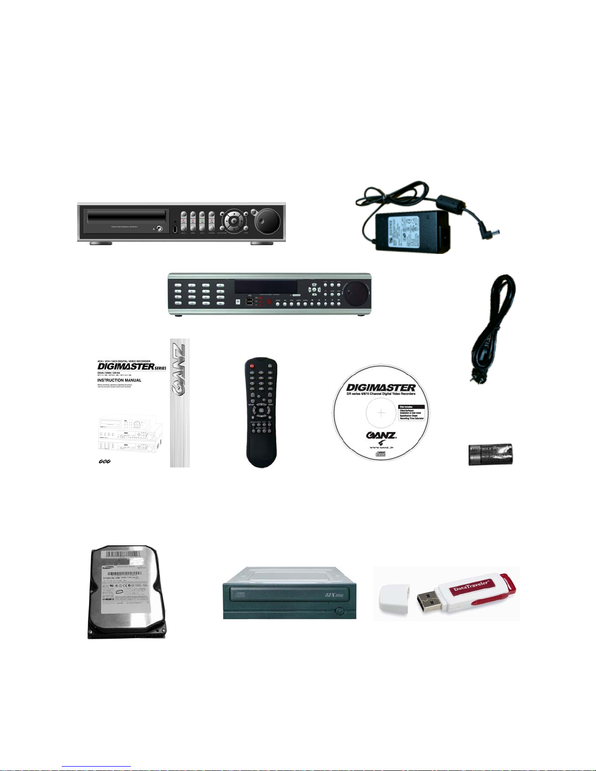
2. Product Contents List
Please confirm that all product contents are present after opening the package.
① Basic Contents
② Optional Contents
DR4N
12V Adaptor
DR8N or DR16N Unit
Remote ControllerInstruction Manual Remote Agent
Installation CD
AC Power Cable
AAA Battery x 2
Internal Hard Disk Drive
Internal CD-RW Drive USB Thumb Drive
7
Specifications & Organization
Specifications & Organization
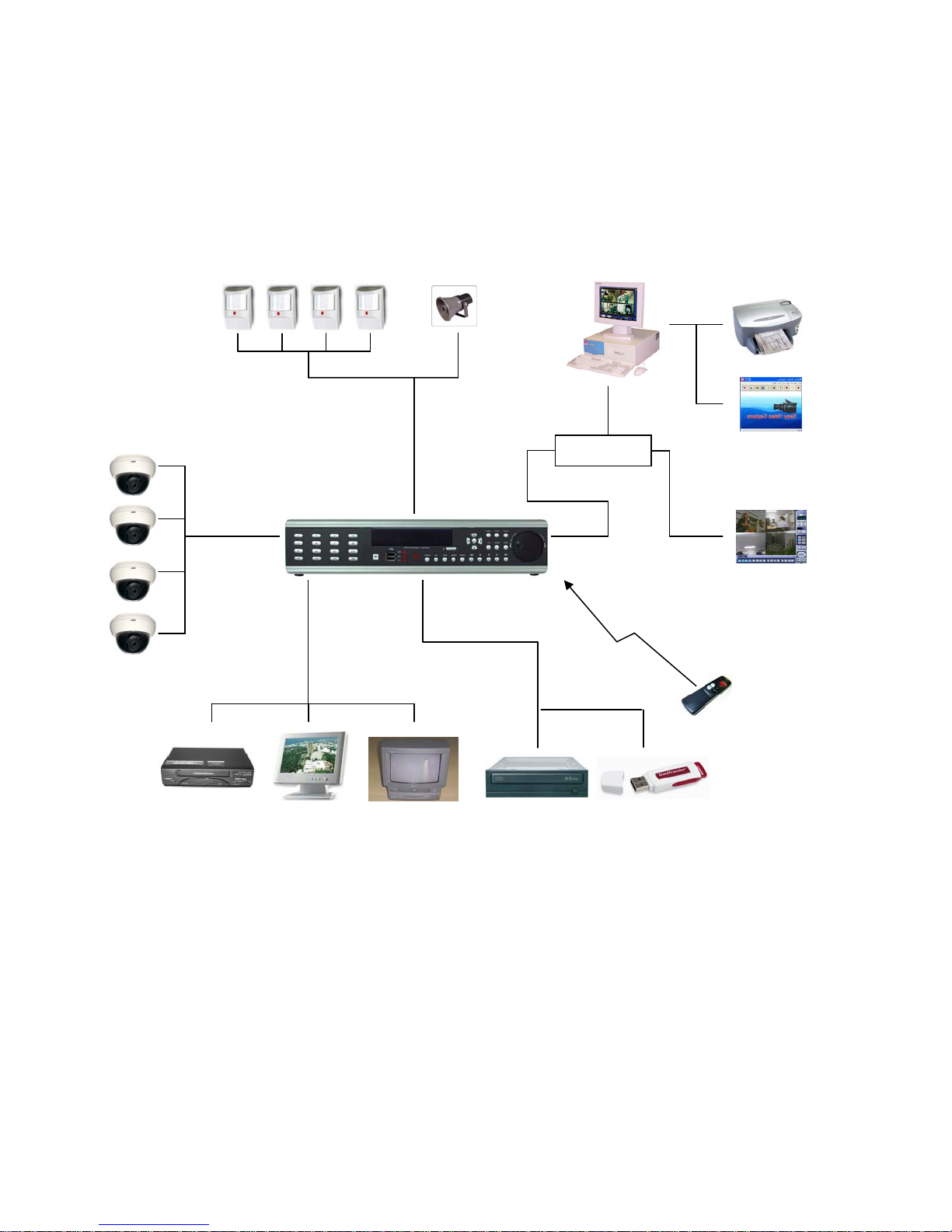
3. System Organization
Camera #1-16
Alarm Sensor #1-16 Relay Out
Alarm Input/Out
Video In
Video Out
Backup
TCP/IP
Remote Client PC Image Printer
NETWORK
AVI Backup
WEB Client
VCR
VGA
Monitor
A/V Monitor
8
CD-RW
Remote
Controller
USB
Product Description
Product Description
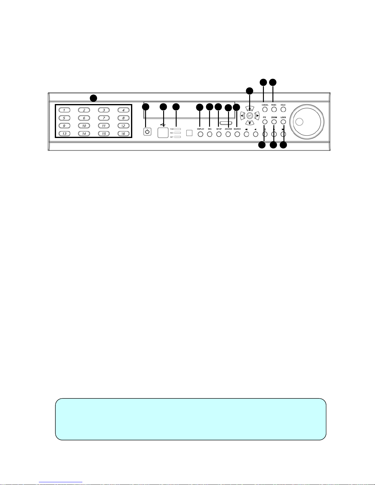
1. Front Panel (8 &16CH)
4
12
13
15
1
11
14
① Power : System Power On/Off
② DISPLAY : Select Screen Division Mode or Rotation Mode
③ SEQUENCE : Select Sequence Screen Mode
④ PANIC : Trigger Panic Recording Mode and Panic Relay Output
⑤ ZOOM : Digital Zoom on Live or Playback Image
⑥ LOCK : Front Panel Lock Button
⑦ ARCHIVE : Go to Archiving Menu
⑧ PTZ : Go to Camera PTZ Control
⑨ SETUP : Go to System Setup Menu
⑩ SEARCH : Go to Search Menu
⑪ USB PORT: USB Port for use of a USB Memory Stick and/or USB HDD Backup.
⑫ RETURN : Cancel / Deselect / Return to Previous Screen
⑬ ENTER : Confirm / Select / Next Screen
⑭ LED Indicator : Indicates Present System Status. (POWER, REC, NETWORK)
⑮ Channel Selection Buttons (1~8/16) : Select Channel or Input Password
- Directional / Navigation Buttons (UP, DOWN, LEFT, RIGHT, ENTER)
- Remote Controller Input Sensor (IR)
- EJECT : Eject CD/DVD-ROM (Optional)
- ◀◀/ ◀ : Focus Adjust (Near/Far) or Reverse Play / Rewind
- Ⅱ: Pause Playback
- ▶ / ▶▶: Iris Adjust (Open / Close) or Forward Play / Fast Forward
- JOG / SHUTTLE : Outer wheel – variable REW or FF; Inner wheel – scroll frame-by frame while PAUSED.
- HOLD : Hold Current JOG / SHUTTLE Position
3
2
9
10
7
5 6
8
Tip
• If the Remote Control IR Sensor is blocked, the Remote Controller will NOT function
properly.
• When a button is pressed on the Front Panel or on the Remote Controller, the DVR
will beep, unless this feature is disabled from : System Setup Æ Audio Æ Buzzer.
9
Product Description
Product Description
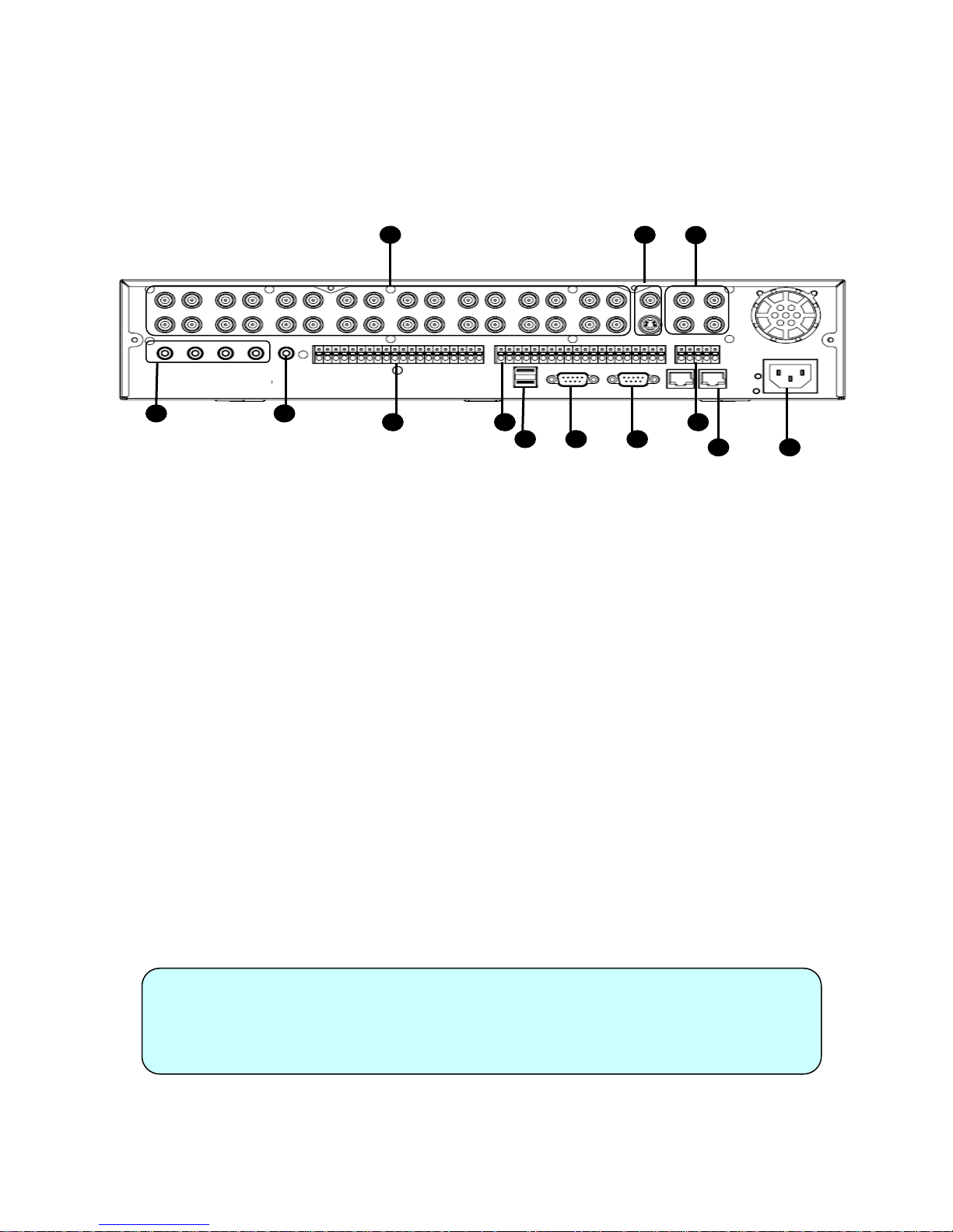
2. Rear Panel (8 & 16CH)
1 2
4
① Video IN / Loop : BNC Video Input Port (1 ~ 8/16), BNC Video Loop Output (1 ~ 8/16)
② Monitor out : BNC Main Monitor Output
SVHS : Output Video by Connected SVHS.
③ Spot #1 ~ #4 : 4/2(8CH) x BNC Output to Individually-Sequenced Spot Monitors
④ Audio In : 4 x RCA Audio Line Input Terminal
⑤ Audio Out : RCA Audio Line Out Terminal
⑥ Alarm : 8/16 x Input TTL Alarm/Sensor Input Terminal
⑦ Relay : 8/16 x Relay Output Terminal
⑧ USB PORT: USB Port for use of a USB Memory Stick and/or USB HDD Backup
⑨ VGA OUT : VGA Main Monitor Output (to a Computer Monitor)
⑩ RS-232C : Serial Configuration Port for Program Debugging
⑪ RS-485 : Serial Interface for PTZ device connection and control
⑫ RJ-45 jack : 10/100 Ethernet LAN/WAN connection (for Remote Access and Configuration)
⑬ AC Power Input
5
76
98 10
3
11
12
13
• When Installing the DVR System, please install components with Power turned OFF.
Tip
• Please Use only the provided AC power cord with this DVR system.
10
Product Description
Product Description
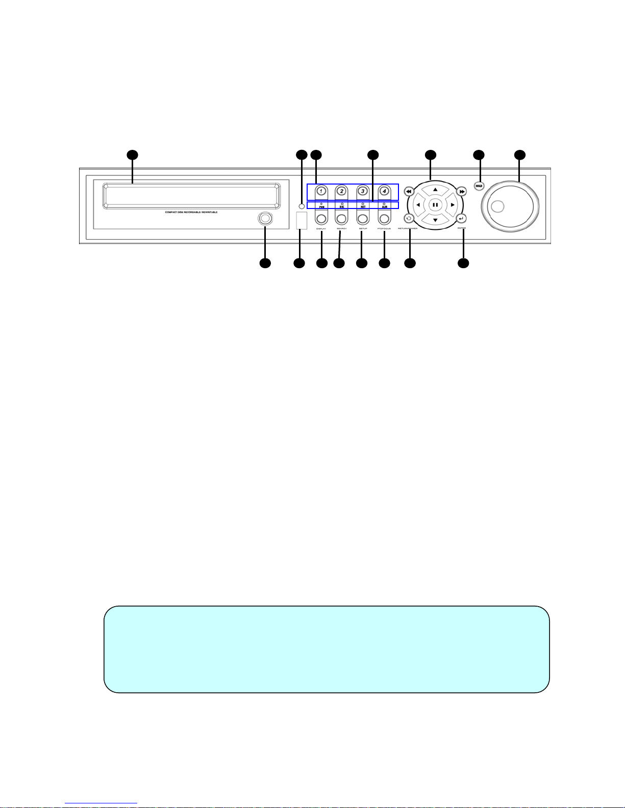
3. Front Panel (4CH)
15
14
11 1298 10 13
1 2 3 4
7
① CD-RW : CD/DVD-RW Device for Backup.
② Channel Selection Button : Select Channel or Input Password.
③ Led Indicator : Indicate Present System Status Information.
(PWR: System On/Off, REC: Record On/Off,
ALARM: Alarm Sensor Detection Status, NET: Client Network Connection Status, )
④ Search Controller : Searching Recorded Data or Control Menu & PTZ/FOCUS.
⑤ HOLD : Hold Jog dial.
⑥ JOG dial
⑦ Eject : Eject CD
⑧ DISPLAY : Select Screen Division Mode or Rotation Mode.
⑨ SEARCH : Go to Search Mode for Searching Data.
⑩ SETUP : Go to System Menu.
⑪ PTZ/FOCUS : Go to Camera PTZ/FOCUS Control.
⑫ RETURN : Cancel Setup or Return to Previous Mode.
⑬ ENTER : Apply Changing Setup.
⑭ Remote Controller Sensor Input.
⑮ USB Port: used with a USB memory stick and/or USB HDD for Backup
65
Tip
• Power is turned OFF within the system GUI, using the Setup -> Shutdown menu.
• Channel Selection Buttons will override the Display Mode.
• The actual appearance of the CD/DVD-RW may differ from the above picture,
depending on the model.
11
SYSTEM CONFIGURE (8CH, 16CH)
SYSTEM CONFIGURE (8CH, 16CH)
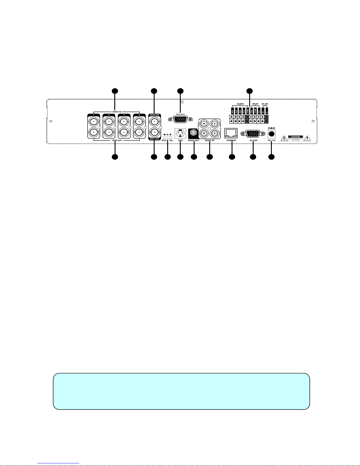
4. Rear Panel (4CH)
1 3 6 11
2 4 75 1298 10 13
① Video In : BNC Port for Connection of DVR & Camera. (4 Camera Connectable)
② Loop Back : Output DVR Camera Video to Loop Back Port. (4 BNC Port)
③ Monitor Out : Output DVR Video to AV Monitor.
④ Spot Out : Output Spot-out Video to AV Monitor.
⑤ NTSC/PAL : Select NTSC or PAL Video Format.
⑥ VGA OUT : Output Video to a VGA Monitor.
⑦ S-Video Out : Output Video to a S-Video device.
⑧ Audio Out : Output Audio Data.
⑨ Audio In : Audio Input Terminal Related with #1~4 Camera.
⑩ Ethernet (TCP/IP) : RJ-45 Jack to connect DVR to Ethernet/LAN for Remote Access.
⑪ Alarm/Relay/RS-485 : Connect Port for Sensor, Relay, & PTZ.
⑫ RS-232C : Connect Port for Program Debug.
⑬ DC Power Input : Power Supply by DC 12V Adaptor.
Tip
• When Installing the DVR System, please install components with Power
turned OFF.
• Please Use only the provided AC power cord with this DVR system.
12
SYSTEM CONFIGURE ––
SYSTEM CONFIGURE
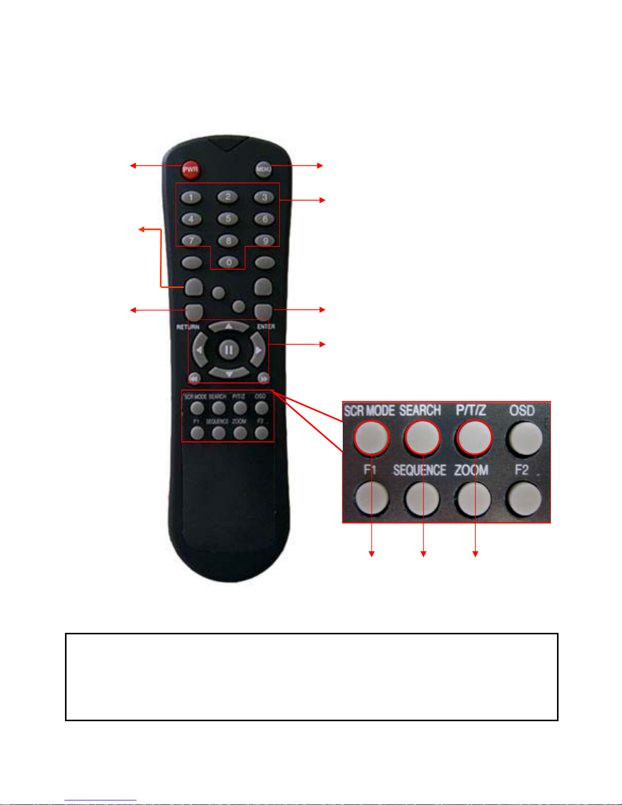
5. Remote Controller
Remote Controller
Remote Controller
POWER
System
ON/OFF
ID Button
Select DVR ID※
RETURN
Cancel /
Deselect
Previous Screen
MENU : Open System Setup Menu
Channel Selection Buttons
ID
ENTER : Apply / Select /Go to Next Screen
Navigation Buttons : Used for Playback Control,
Menu Navigation, and PTZ/Focus Control
※ If there are many DVRs on stack, each DVR must be set different ID then Remote controller set each
ID on DVR. Can control all DVRs on one Remote controller by each ID.
How to set ID on the remote controller
: Press the ID button then displayed INPUT ID statement.
Press the set ID and Press the RETURN button (The default ID is 01). For DVR ID, see the page44.
For returning to the original situation, press the ID button again.
And Input the 255 and press the RETURN button of remote controller.
Change Display
Mode
13
Search Menu
PTZ/IRIS Mode
CONNECT & POWER ON
CONNECT & POWER ON
• Connect up to 16 CAMERA INPUTS as necessary.
The DVR also has LOOP OUTPUTS so that any signals can be fed to other equipment if required.
Termination is automatically set by the DVR depending on connection type.
• Connect one or more monitors to the DVR using the COMPOSITE, VGA or S-VIDEO connections
• Connect power to the DVR. The DVR checks for proper power connection and emits two beeps.
Press the POWER BUTTON on the front panel of the DVR to begin operation.
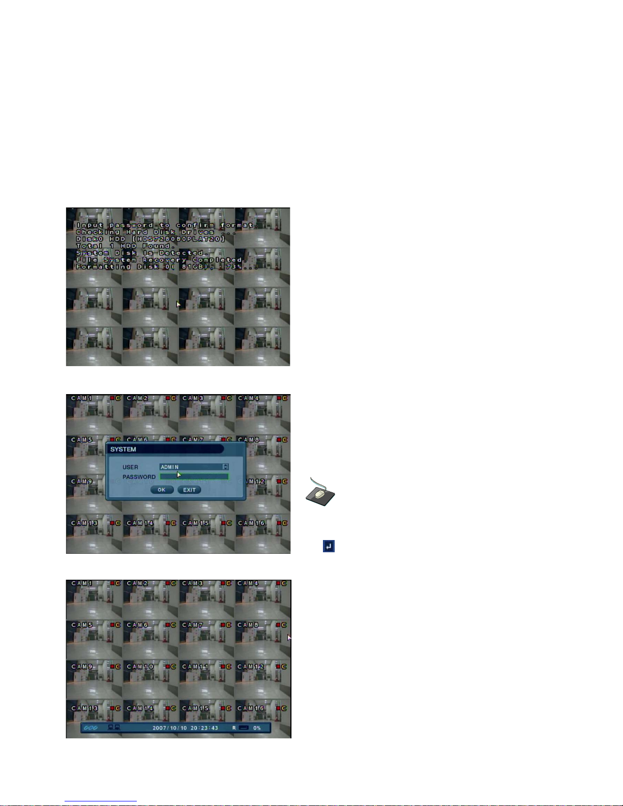
The DVR startup screen detects and checks the status
of hard drives and the CDRW / DVR-RW drive.
After startup diagnostics are complete, the operator must
logon to the system. The default user name is ‘ADMIN’.
Using the CHANNEL SELECTION buttons, key in
the default password of ‘1234’ and press the ENTER
button.
Double click on the Password field, and the Virtual
Keyboard will appear. Enter the password and click
the button to confirm.
The DVR begins normal operation and shows the
default display of all 16 channels.
The status bar at the bottom of the screen shows
current time and date and percentage of hard drive used.
A title for each channel is shown.
The red square and letter ‘T’ in the top right of each
channel display shows that the channel is recording in
Timer/Schedule mode, or ‘M’ for motion recording mode.
14
LIVE DISPLAY
LIVE DISPLAY
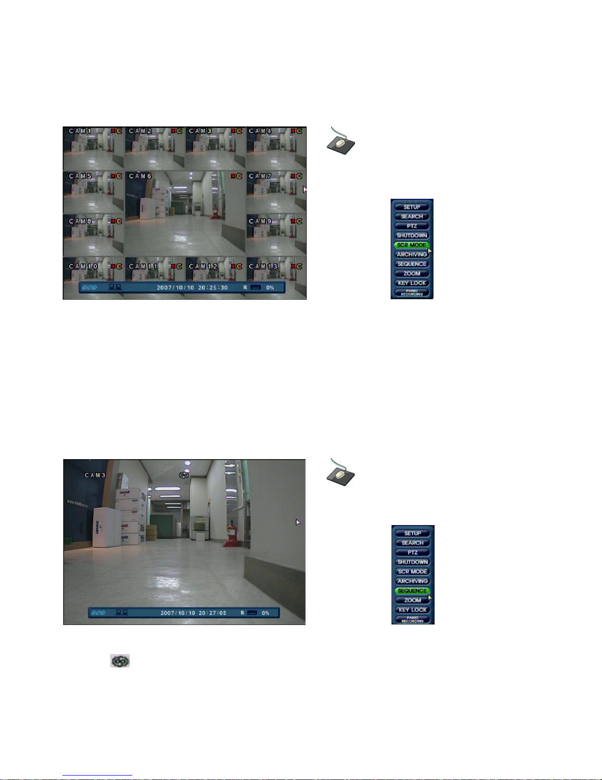
DIVISION SCREEN
Click the right mouse button on the Live Display
screen and Click SCR MODE.
8 different display modes are supported by the 16 channel DVR.
By repeatedly pressing the DISPLAY button, the operator can choose between single-channel,
4-channel, 6-channel, 8-channel, 9-channel, 13-channel, 16-channel and single-channel sequence modes.
All the display modes are static with the exception of the sequence mode. In this mode, the sequence
symbol ( ) is displayed and each channel is shown in full screen for a set period of time (default 3 sec)
before switching to the next channel.
The sequence runs indefinitely until a different display mode is chosen.
Click the right mouse button on the Live Display
screen and Click the SEQUENCE menu.
15
LIVE DISPLAY
LIVE DISPLAY
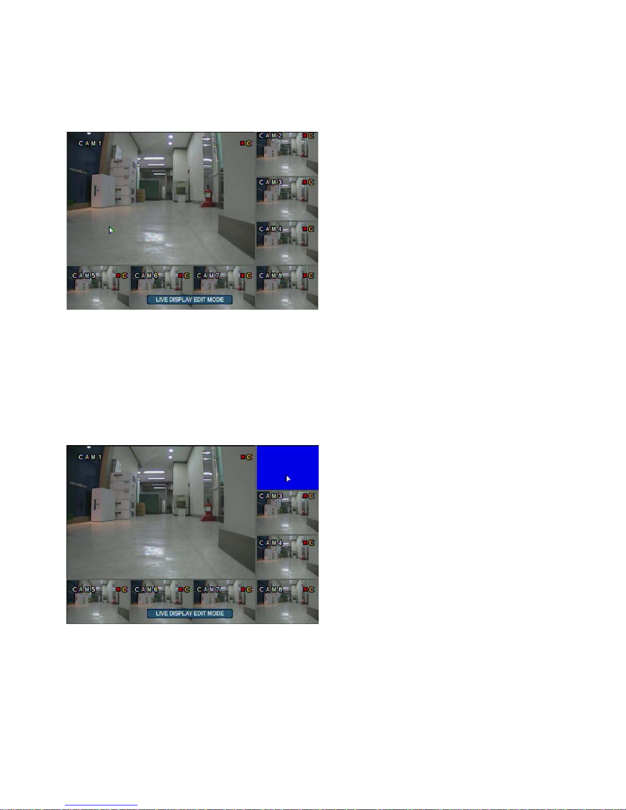
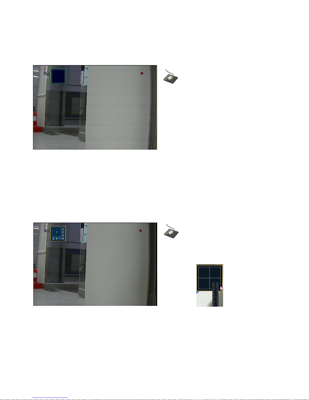
LIVE Display Edit Mode
For each multi screen view mode, the operator can decide which channels to view and in what position.
Use the DISPLAY button to choose the multi screen mode to edit and then press ENTER to select LIVE
DISPLAY EDIT MODE.
In this example, the default 8 screen mode displays channels 1-8. To display channel 10 instead of
channel 5:
Using the CHANNEL SELECTION buttons, press number 5 -- channel 5 will change to a blue screen.
Now, you may press number 10 to put that channel in the place where channel 5 was.
Press Enter to confirm the change and exit Live Display Edit Mode, or select another channel to edit.
16
LIVE DISPLAY
LIVE DISPLAY
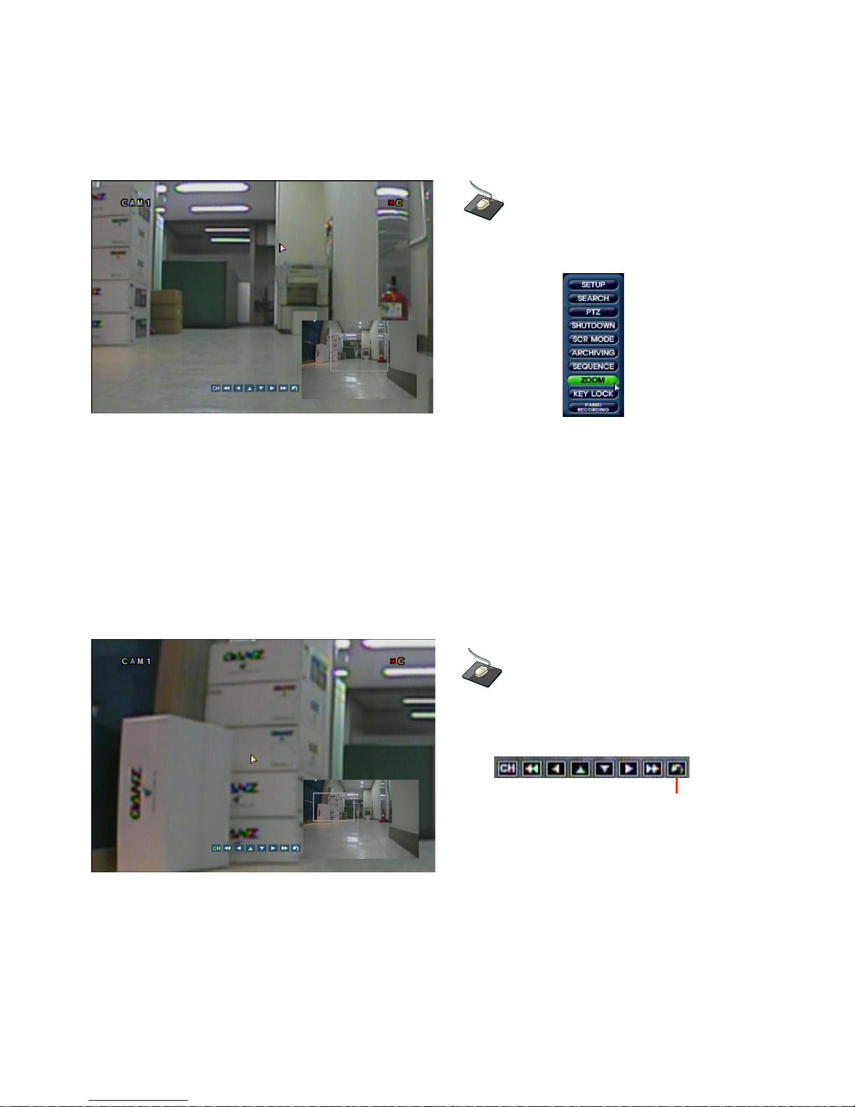
Digital Zoom
Click the right mouse button on the Live Display
screen and Click the ZOOM menu.
When viewing a channel in full screen, the operator can zoom in to a particular area (by up to 8x).
To use Digital Zoom, select the required channel and press the ZOOM button. The small window at bottom
right shows the full image and the main display area shows the zoomed portion.
The Digital Zoom operation can only be done within Live View Mode.
Use the Return button to exit to Live View Mode.
RETURN
To adjust the zoom level, turn the SHUTTLE WHEEL clockwise to increase zoom or counter-clockwise
to decrease zoom. To move the zoom area around the image, use the CURSOR KEYS to adjust the
position of the zoom square.
Press the RETURN button to return to normal live display mode.
17
LIVE DISPLAY
LIVE DISPLAY
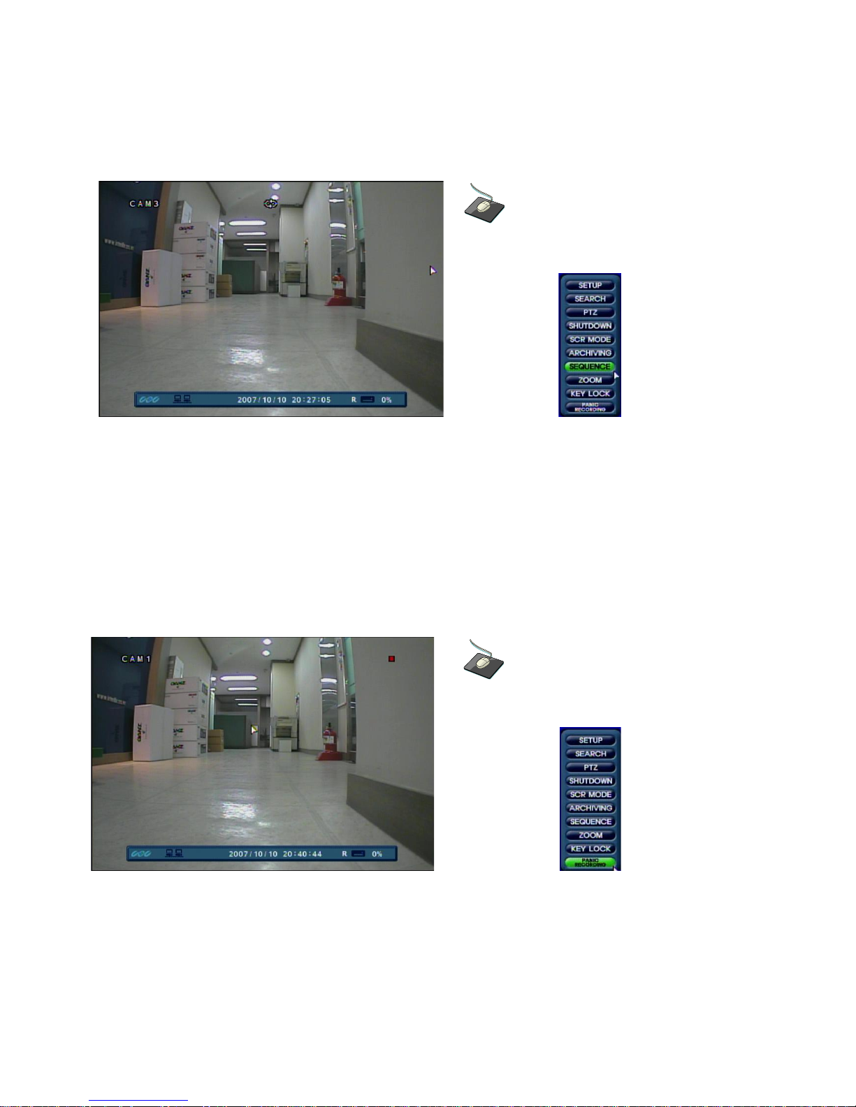
Sequence
Click the right mouse button on the Live Display
screen and Click the SEQUENCE menu.
Press the SEQ button. Each channel is shown in full screen for a set period of time (default 3 sec)
before switching to the next channel.
To stop the sequence on a particular channel, press the SEQ button again.
More complex sequences can be programmed through the setup menu (page 25).
Panic Recording
Click the right mouse button on the Live Display
screen and Click the PANIC RECORDING menu.
Panic recording will override all standard recording settings to provide, by default, continuous recording on
all channels. The Panic Recording settings can be edited within the Record Menu.
Press the PANIC button. The top right of the display shows a red square only to indicate that the DVR is in
panic recording mode.
Press the PANIC button again to return to normal Timer or Motion recording mode.
18
LIVE DISPLAY
LIVE DISPLAY
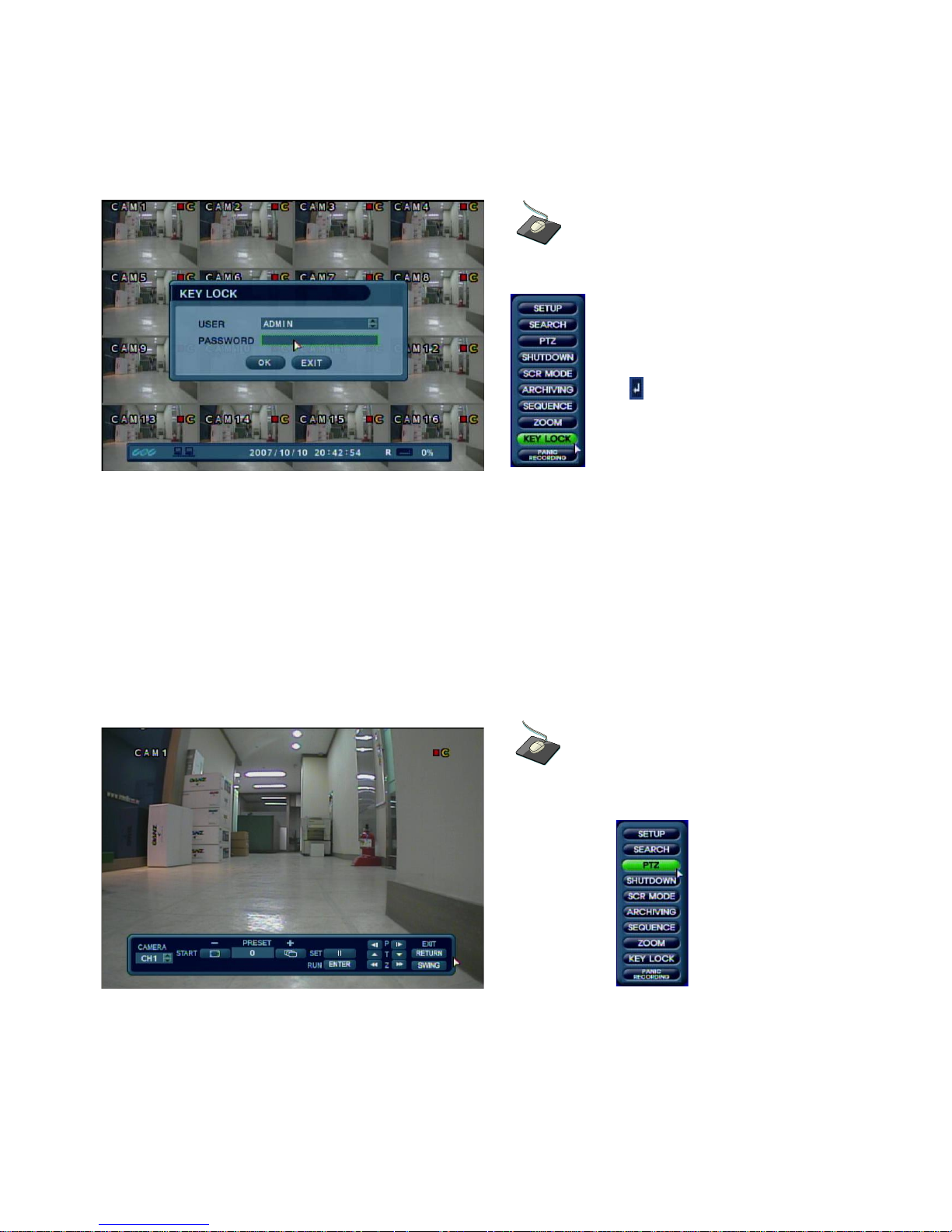
Key Lock Function
Click the right mouse button on the Live Display
screen and Click the KEY LOCK menu.
Double click on the Password field,
and the Virtual Keyboard will appear.
Then enter the password and click
the button.
An operator with ADMIN rights can choose to lock the DVR front panel to prevent any un authorized control.
Press the LOCK button, enter the default password ‘1234’
And press ENTER. All buttons are now disabled.
To unlock, press the LOCK button again and enter the default password ‘1234’.
PTZ Camera Control
Click the right mouse button on the Live Display
screen and Click the PTZ menu.
Speed domes and other telemetry devices connected to the DVR, can be fully controlled from the front panel.
In live display mode, press the PTZ button. To select a camera to control, use the CHANNEL SELECTION
buttons. Pan and tilt movement is controlled by the CURSOR KEYS, zoom is controlled by turning the
SHUTTLE WHEEL.
Presets can be set with the PAUSE button; recall a preset by selecting a preset number and pressing ENTER.
19
LIVE DISPLAY
LIVE DISPLAY
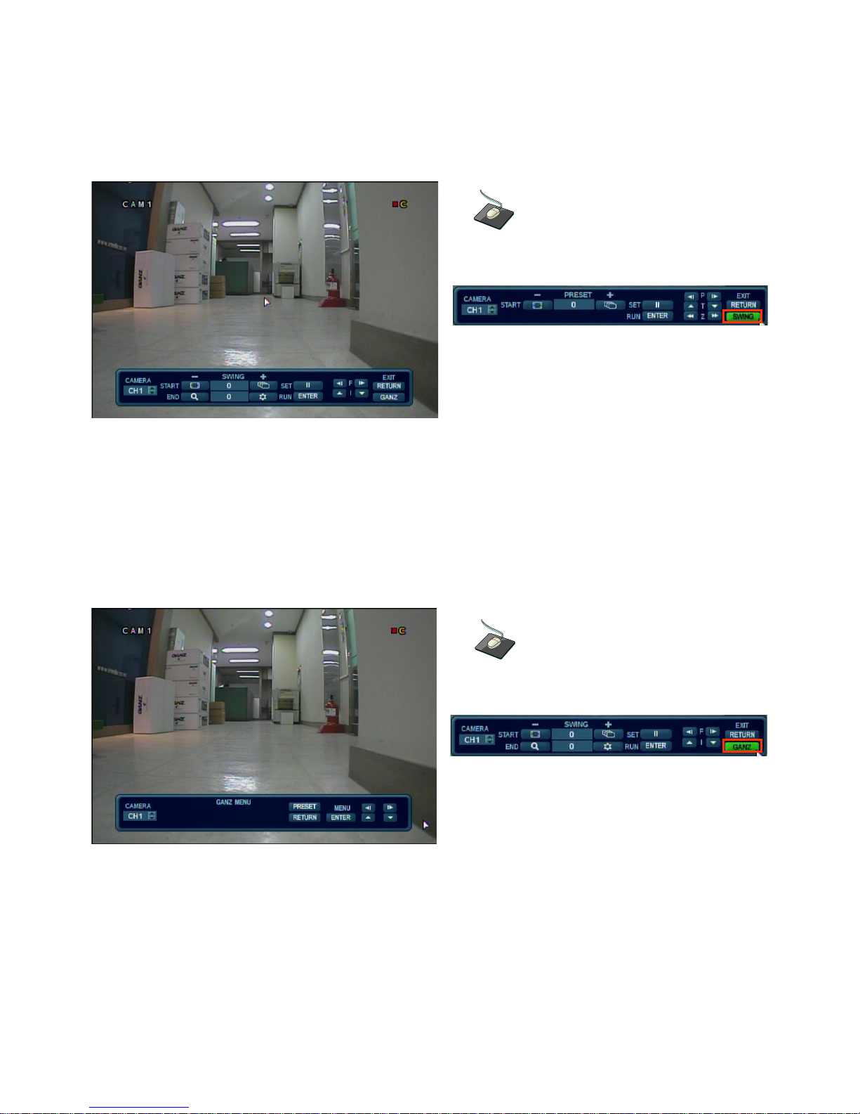
PTZ Camera Control (continued)
Click the SWING menu.
◀ & ▶ controls focus, ▲ & ▼ controls the iris.
Press DISPLAY or SEQ buttons to decrease or increase the swing number (sequence of preset positions).
Press PAUSE to program the swing pattern, or ENTER to recall a pre-programmed swing pattern.
Press RETURN to exit PTZ mode and return to live view.
Click the GANZ menu to enter the PTZ internal
OSD menu (GANZ PTZ cameras only).
Use the directional buttons to navigate the OSD.
Press ENTER to confirm a selection.
Press RETURN to exit the OSD menu control.
20
SYSTEM SETUP
SYSTEM SETUP
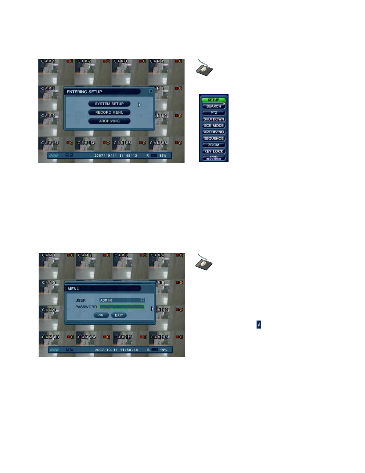
Right-Click the mouse in Live Display Mode.
Left-Click the SETUP menu.
When using the DVR Front Panel or the Handheld IR Remote Controller, to navigate around any items in
the setup menu, use the CURSOR KEYS and the ENTER and RETURN buttons.
In general, the ENTER button is used to select and change a particular item and the RETURN
button is used to cancel a change or exit from a particular setup screen.
To setup all main system functions, highlight SYSTEM SETUP and press ENTER.
Using the mouse, click the SYSTEM SETUP button
to select the system setup menu.
Double click on the Password field, and the
Virtual Keyboard will appear. Then enter the
password and click the button.
From the Front Panel, press the SETUP button to bring up the menu login screen.
Only operators with ADMIN rights can configure the DVR. Enter the default password of ‘1234’.
21
SYSTEM SETUP
SYSTEM SETUP
DISPLAY
: To setup the various display options, highlight DISPLAY and press ENTER.
DISPLAY - OSD
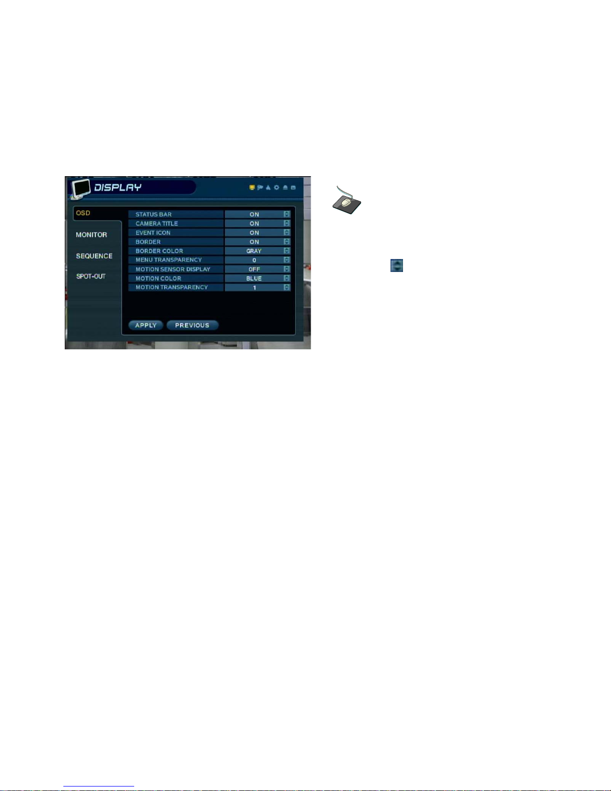
Click the OSD menu. Click on a field to change its
setting.
Then click the button to toggle the setting.
STATUS BAR : Turns the status bar at the bottom of the live display ON or OFF.
CAMERA TITLE : Determines whether the camera title is displayed.
EVENT ICON : Determines whether the DVR recording status is shown at the top right of each channel
window.
BORDER : Determines whether there is a border grid around each channel in multi-screen display mode.
BORDER COLOR : If the border is ON, the operator can choose the color of the grid lines.
MENU TRANSPARENCY : During menu setup, the live view can be seen behind the menu screen.
Changing this value determines whether the live view is more (higher value) or less (lower value) visible.
MOTION SENSOR DISPLAY : If false motion recording is occurring, the operator can use this feature to
determine and rectify the cause in realtime.
OFF – normal display mode.
ACTIVE – areas where motion is detected are highlighted with colored blocks.
INACTIVE – areas where no motion is detected are highlighted with colored blocks.
MOTION COLOR: The color of the blocks displayed when MOTION SENSOR DISPLAY is set to
ACTIVE or INACTIVE.
MOTION TRANSPARENCY : Determines the transparency of the colored blocks when MOTION
SENSOR DISPLAY is set to ACTIVE or INACTIVE.
To change any of these settings, highlight OSD and press ENTER to select. Use the CURSOR KEYS to
navigate to the option required. Press ENTER to select the option (the cursor changes to yellow) and use
the CURSOR KEYS to change the setting. Click APPLY to save the setting or PREVIOUS to cancel.
22
SYSTEM SETUP
SYSTEM SETUP
DISPLAY : MONITOR
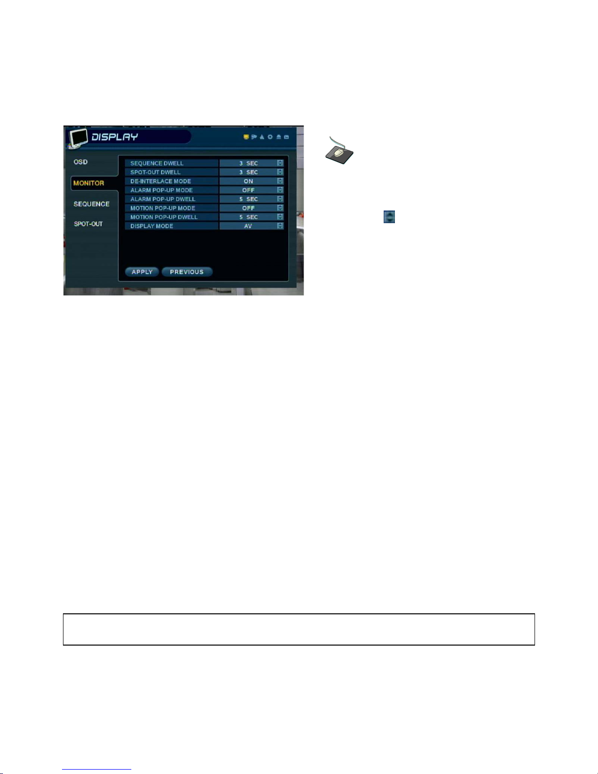
Click the MONITOR menu. Click on a field to
change its setting.
Then click the button to toggle the setting.
SEQUENCE DWELL : The time that each screen is displayed in a sequence operation.
SPOT-OUT DWELL : The time that each screen is displayed on the spot monitor outputs.
DE-INTERLACE MODE : When recording any channels in D1 resolution (704 x 480) this should be set to
ON to prevent motion distortion du rin g pl a yb ack.
ALARM POP-UP MODE : When set to ON, an alarm input will cause the associated channel to display
full screen.
ALARM POP-UP DWELL : Determines how long the full screen popup is displayed after an alarm input.
If the alarm condition continues, the popup screen is displayed constantly.
MOTION POP-UP MODE : When set to ON, motion detection will cause the associated channel to display
full screen.
MOTION POP-UP DWELL : Determines how long the full screen popup is displayed after motion detection.
If motion continues, the popup screen is displayed constantly.
DISPLAY MODE : The DVR output can be optimized for display on a VGA or AV (CRT) monitor.
To change any of these settings, highlight MONITOR and press ENTER to select.
Use the CURSOR KEYS to navigate to the option required. Press ENTER to select the option (the cursor
changes to yellow) and use the CURSOR KEYS to change the setting. Press APPLY to save the setting
or PREVIOUS to cancel.
Note: When changing between displ ay modes, you must shutdown and re start the DVR before
any changes will take effect.
23
SYSTEM SETUP
SYSTEM SETUP
DISPLAY : SEQUENCE
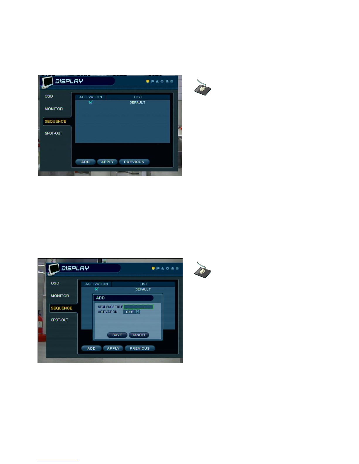
Click the SEQUENCE menu.
When the SEQ button is pressed, the default sequence will cycle through all 16 channels, one by one.
Sequence setup allows the operator to define a custom sequence using mixed multi-screen views and any
desired channels.
To add a new sequence, highlight ADD and press ENTER.
Sequence title is highlighted – press ENTER to bring up the virtual keyboard. Use the virtual keyboard to
type in a name or reference number for the new sequence.
Click the ADD menu to set up a new sequence.
24
SYSTEM SETUP
SYSTEM SETUP
DISPLAY : SEQUENCE (continued)
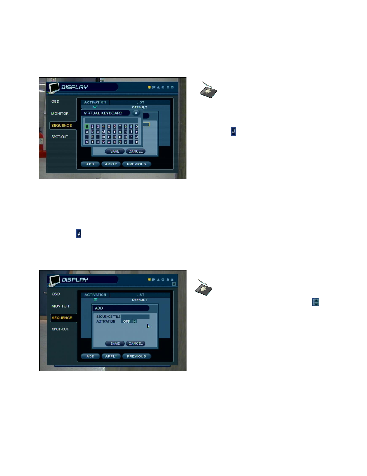
Double click on the SEQUENCE TITLE field.
The Virtual Keyboard will appear. Enter the title,
and click the button to confirm.
From the DVR Front Panel or the IR Remote Controller, move around the virtual keyboard using the
CURSOR KEYS and press ENTER to select a character.
To delete a character, use ← .
To use CAPS and access symbols, use ↑.
To exit, use .
Click on the ACTIVATION field and use the
button to toggle ON/OFF.
In order to activate the newly-created sequence, set ACTIVATION to ON, highlight SAVE and press
ENTER to display the sequence programming screen.
25
SYSTEM SETUP
SYSTEM SETUP
DISPLAY : SEQUENCE (continued)
Double click on the first screen of the sequence,
and the box will be outlined in yellow.
Each time the screen is clicked, the display mode
will change.
The square on the top left of the display represents the first sequence screen to be displayed.
To edit the screen, press ENTER to turn the cursor yellow. Using the up and down CURSOR KEYS,
choose the display mode (single-channel or various multi-screen modes).
Right-click on a section of the multi-screen display.
Then click the desired camera number to assign it.
When the correct screen type is displayed, use the CHANNEL SELECTION buttons to enter the channels
into each section of the multi screen modes.
Note: Only one instance of each channel can be displayed.
To remove a channel, press the appropriate CHANNEL SELECTION button again.
26
 Loading...