

Ganz digimaster DR8NRT, digimaster DR16NRT Instruction Manual
1

Specification & Organization -------------------------------------------------- 5
Spe c i f ications --------------------------------------------------------- 5
Product Contents List -------------------------------------------------- 7
System Organization ---------------------------------------------------- 8
Product Description -------------------------------------------------------- 9
Front panel description --------------------------------------------------- 9
Rear panel description --------------------------------------------------- 10
Remote Controller description --------------------------------------------- 11
HDD, DVD-RW Connect ----------------------------------------------------------- 12
Power On ---------------------------------------------------------------- 13
Live Display --------------------------------------------------------------- 14
Configuring the live display ---------------------------------------------- 14
PTZ -------------------------------------------------------------------- 15
Search ----------------------------------------------------------------- 16
Normal Search -------------------------------------------------------- 16
Seque n c e Sea r c h ------------------------------------------------------ 21
Thumbnail Search ----------------------------------------------------- 22
S m a r t S ea rc h - --------------------------------------------------- 23
Backup ----------------------------------------------------------- 24
Ba c ku p -------------------------------------------------------------- 24
Backup Data Management ----------------------------------------------- 25
Configuration-System ------------------------------------------------------ 26
Camera --------------------------------------------------------- 26
Alarm/Event ------------------------------------------------------ 29
Display ------------------------------------------------------- 35
Audio ----------------------------------------------------------- 38
User ------------------------------------------------------ 39
Network ------------------------------------------------------- 41
S y s t e m ------------------------------------------------------- 43
S t o r age ----------------------------------------------------- 45
2

Configuration-Record -------------------------------------------------- 46
Record mode --------------------------------------------------------- 46
Normal record ---------------------------------------------------- 48
Intensive r ecord - ---------------------------------------------------- 50
Panic record ----------------------------------------------------- 52
Sequence -------------------------------------------------------- 53
Digital Zoom ------------------------------------------------------- 54
Keylock ---------------------------------------------------------------- 55
Panic Start/Stop ----------------------------------------------------------- 56
Shutdown ---------------------------------------------------------------- 57
Error Code List ---------------------------------------------------------- 57
RemoteSW installation ------------------------------------------------------- 58
System Requirement ---------------------------------------------------- 58
Introduce ------------------------------------------------------------ 59
RemoteSW Local Setup ----------------------------------------------------- 60
local setup ---------------------------------------------------- 62
RemoteSW Search --------------------------------------------------------- 64
Search Function Introduce ------------------------------------------------ 64
Search M ethod -------------------------------------------------------- 65
Sear c h Opt i o n - ------------------------------------------------------- 66
RemoteSW DVR System Setup ------------------------------------------------- 71
Camera ------------------------------------------------------------ 72
A l ar m/ E ven t - -- -- -- - ------------------------------------------------ 73
Display ---------------------------------------------------------- 76
Audio ----------------------------------------------------------- 78
User ----------------------------------------------------------- 78
RemoteSW DVR Record Setup ------------------------------------------------- 79
Record Mode ---------------------------------------------------------- 80
Normal record -------------------------------------------------------- 81
Intensive record -------------------------------------------------------- 83
Panic record ---------------------------------------------------------- 84
Web Client Installation -------------------------------------------------- 85
3

IMPORTANT SAFETY INSTRUCTIONS
1) Read these instructions.
2) Keep these instructions.
3) Heed all warnings.
4) Follow all instructions.
5) Do not use this apparatus near water.
6) Clean only with a dry cloth.
7) Do not block any of the ventilation openings. Install in accordance with the manufacturer's
instructions.
8) Do not install near any heat sources such as radiators, heat registers, stoves, or other apparatus
that produce heat.
9) Do not defeat the safety purpose of the polarized or grounding type plug. A polarized plug has
two blades with one wider than the other.
A grounding type plug has two blades and a third grounding prong.
The wide blade or the third prong is provided for your safety.
When the provided plug does not fit into your outlet, consult an electrician for replacement
of the obsolete outlet.
10) Protect the power cord from being walked on or pinched particularly at plugs, convenience
receptacles, and the point where they exit from the apparatus.
11) Only use the attachments/accessories specified by the manufacturer.
12) Use only with a cart, stand, tripod, bracket, or table specified by the manufacturer, or sold
with the apparatus.
When a cart is used, use caution when moving the cart/apparatus combination to avoid injury
from tip-over.
13) Unplug this apparatus during lightning storms or when unused for long periods of time.
14) Refer all servicing to qualified service personnel. Servicing is required when the apparatus
has been damaged in any way, such as power supply cord or plug is damaged, liquid has
been spilled or objects have fallen into the apparatus, the apparatus has been exposed to
rain or moisture, does not operate normally, or has been dropped.
15) This equipment is indoor use and all the communication wirings are limited to inside of the
building.
16) The socket-outlet shall be installed near the equipment and shall be easily accessible.
17) CAUTION
RISK OF EXPLOSION IF BATTERY IS REPLACED BY AN INCORRECT TYPE.
DISPOSE OF USED BATTERIES ACCORDING TO THE INSTRUCTIONS.
# Operation Max temperature : 40℃
# USB Load condition: USB Ports( 5 Vdc, Max. 500 mA)
4

SPECIFICATION&ORIGANIZATION
Specifications
MODEL DR8NRT,DR16NRT
Operation PENTAPLEX PENTAPLEX performance
( Simultaneous Live Display/Recording/Playback/Archiv ing/
Networking effectively without interfering each operations)
Video in Channels 16/8
Connection BNC, 1.0Vpp composite 75ohm balanced
Loop through BNC,1.0Vpp composite 75ohm unbalanced, auto termination
Audio in Channels 4
Connection line level unbalanced
Main Displays BNC 1.0Vpp composite 75ohm unbalanced
VGA 15 pin D-SUB 1024 x 768 @ 60Hz
Screen display modes 1 , 4 , 9 , 16 User defined channels for each mode
Sequence Adjustable dwell time, user defined sequences
Spot displays Channels 4 fully programmable
Connection BNC, 1.0Vpp composite 75ohm unbalanced
Display mode Full screen sequence, adjustable dwell time
Audio out Channels 1
Connection RCA, line level unbalanced
External alarm Input s 16(16 Open collector TR), NO or NC common ground
Outputs 16, high(+5V) or low(0V) selectable, common ground
User interface On screen display GUI, alpha blending
Control Front panel/IR Remote/USB Mouse
Recording Video CODEC MPEG-4
Resolution options for each channel CIF (352 x 240, 352 x 288), 2 CIF (704 x 240, 704 x 288), D1 (704 x 480, 704 x 576)
Maximum total frame rate 480/240FPS(NTSC) / 400/200 FPS (PAL)
Image quality Highest, High, Standard, Low
Pre-event recording 5 seconds max
Recording modes Continuous / Motion detection / Alarm / User event / Panic
Frame rate options for each channel 30 – 15 – 7.5 – 4 – 2 – 1
Schedule Configurable recording time
limits
Weekly / Daily per Camera
Audio Audio inputs independently assigned to each channel
Motion detection 16 x 16 selectable grid with 10 levels of sensitivity
Covert recording Yes, selectable by channel
5

Camera title English and Numeric
Playback Speed Forward / reverse. 1x, 2x, 3x, 4x, 8x, 16x, 32x, 64x, 128x
Control Front panel buttons and Jog / Shuttle /USB Mouse
Search method Calendar / timeline, event log, Sequence, Thumbnail, Smart Search
Split screen display modes 1,4,16
Audio synchronization Yes at any frame rate
Archiving Storage DVD±RW, USB Memory stick, Network
Format Watermarked AVI
Archive data Independent channels selection (video / audio), backup log, event log
Time Time zone Worldwide, Selectable
DST Yes
PTZ RS-485 Multi protocol, baud rate and speed control for each channel
System Watchdog Yes
Abnormal shutdown dete ction Yes, with system auto recovery
HDD error detection Yes, SMART monitoring
Network Connection RJ45, 10 / 100 Ethernet
DHCP Yes
DDNS Yes
Two way network audio Yes
Bandwidth management Y es
Remote client Client software Yes, Included
Remote configuration Yes
Remote PTZ control Yes
Email event notification Yes
Storage Maximum Capacity Not limited
Storage 4 x HDD maximum
Recording options Write once / Overwrite
Event handling Source Alarm in, motion detection, video loss, HDD error, User event
Action Record, alarm out, email notification, log, remote client popup, buzzer, full screen
popup
Security User levels ADMIN, MANAGER, USER
Key Lock Yes, password protected
Physical Dimensions 428mm(w) x 475mm(d) x 93mm(h)
Weight 12Kgs
6
SPECIFICATION&ORIGANIZATION
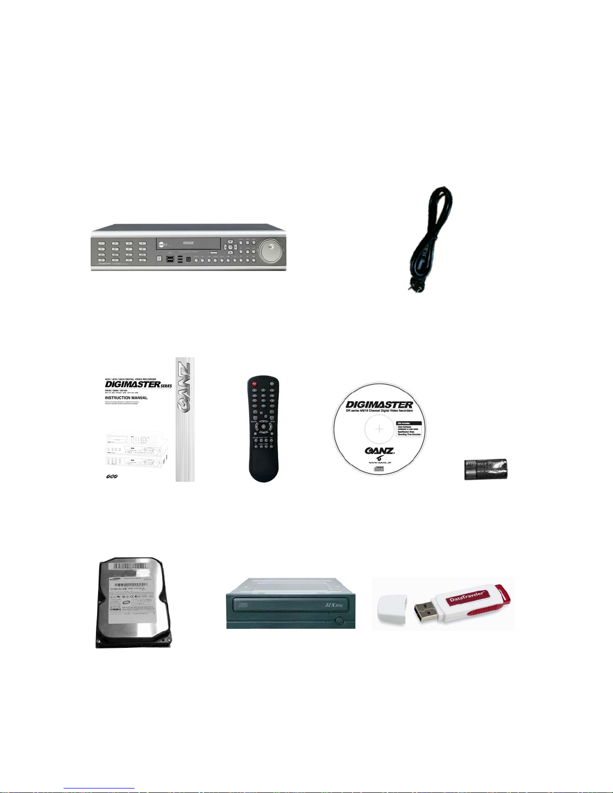
Product Contents List
Please check if all the product contents are present after opening the package.
① Basic Contents
② Optional Contents
Internal Hard Disk Drive
DR8NRT,16NRT Unit
Remote Controller Instruction Manual
Remote Agent
Installation CD
Internal DVD-RW Drive USB Thumb Drive
AC Power Cable
AAA Battery x 2
7
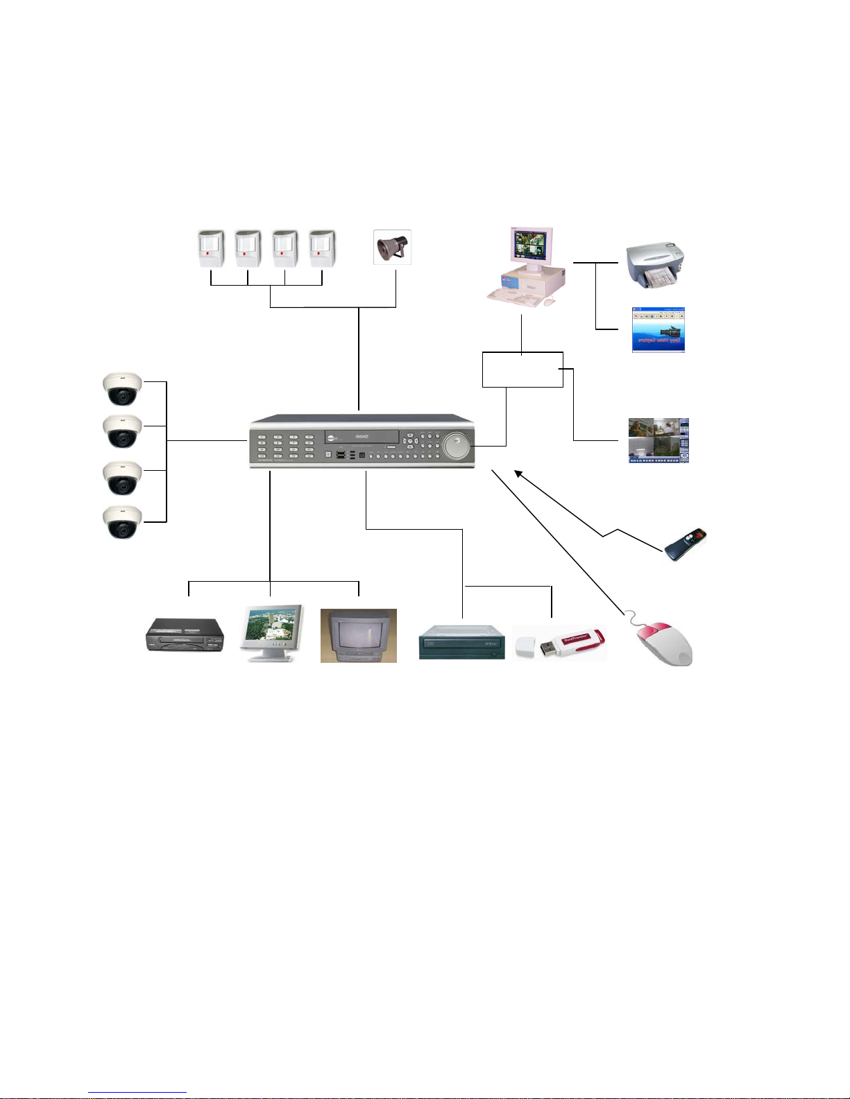
System Organization
Camera
Video In
VCR
SPECIFICATION&ORIGANIZATION
Alarm Sensor Relay Out
Alarm Input/Out
TCP/IP
Video Out
VGA
Monitor
A/V Monitor
Backup
Remote Client PC Image Printer
NETWORK
DVD-RW
USB
AVI Backup
WEB Client
Remote
Controller
USB Mouse
8
PRODUCT DESCRIPTION
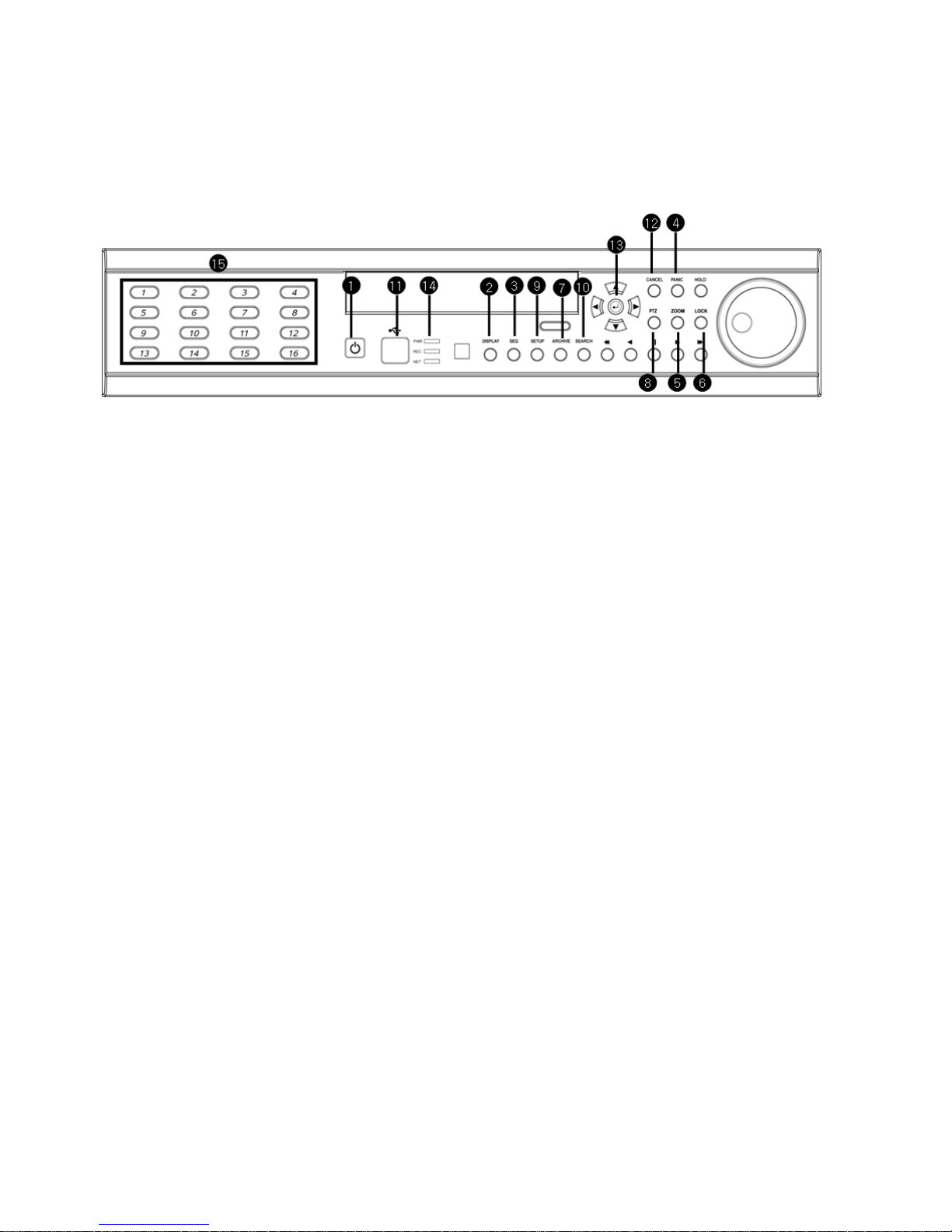
Front Panel
① Power : System Power On/Off
② DISPLAY : Select Screen Division Mode or Rotation Mode
③ SEQUENCE : Select Sequence Screen Mode
④ PANIC : Trigger Panic Recording Mode and Panic Relay Output
⑤ ZOOM : Digital Zoom on Live or Playback Image
⑥ LOCK : Front Panel Lock Button
⑦ ARCHIVE : Go to Archiving Menu
⑧ PTZ : Go to Camera PTZ Control
⑨ SETUP : Go to System Setup Menu
⑩ SEARCH : Go to Search Menu
⑪ USB PORT: USB Port for use of a USB Memory Stick and/or USB HDD Backup.
⑫ Mouse left Click
⑬ Mouse Right Click
⑭ LED Indicator : Indicates Present System Status. (POWER, REC, NETWORK)
⑮ Channel Selection Buttons (1~8/16) : Select Channel or Input Password
- Directional / Navigation Buttons (UP, DOWN, LEFT, RIGHT, ENTER)
- Remote Controller Input Sensor (IR)
- EJECT : Eject DVD-RW
- ◀ ◀ / ◀ : Focus Adjust (Near/Far) or Reverse Play / Rewind
- Ⅱ: Pause Playback
- ▶ / ▶ ▶ : Iris Adjust (Open / Close) or Forward Play / Fast Forward
- JOG / SHUTTLE : Outer wheel – variable REW or FF; Inner wheel – scroll frame-by frame while
PAUSE.
- HOLD : Hold Current JOG / SHUTTLE Position
9
PRODUCT DESCRIPTION
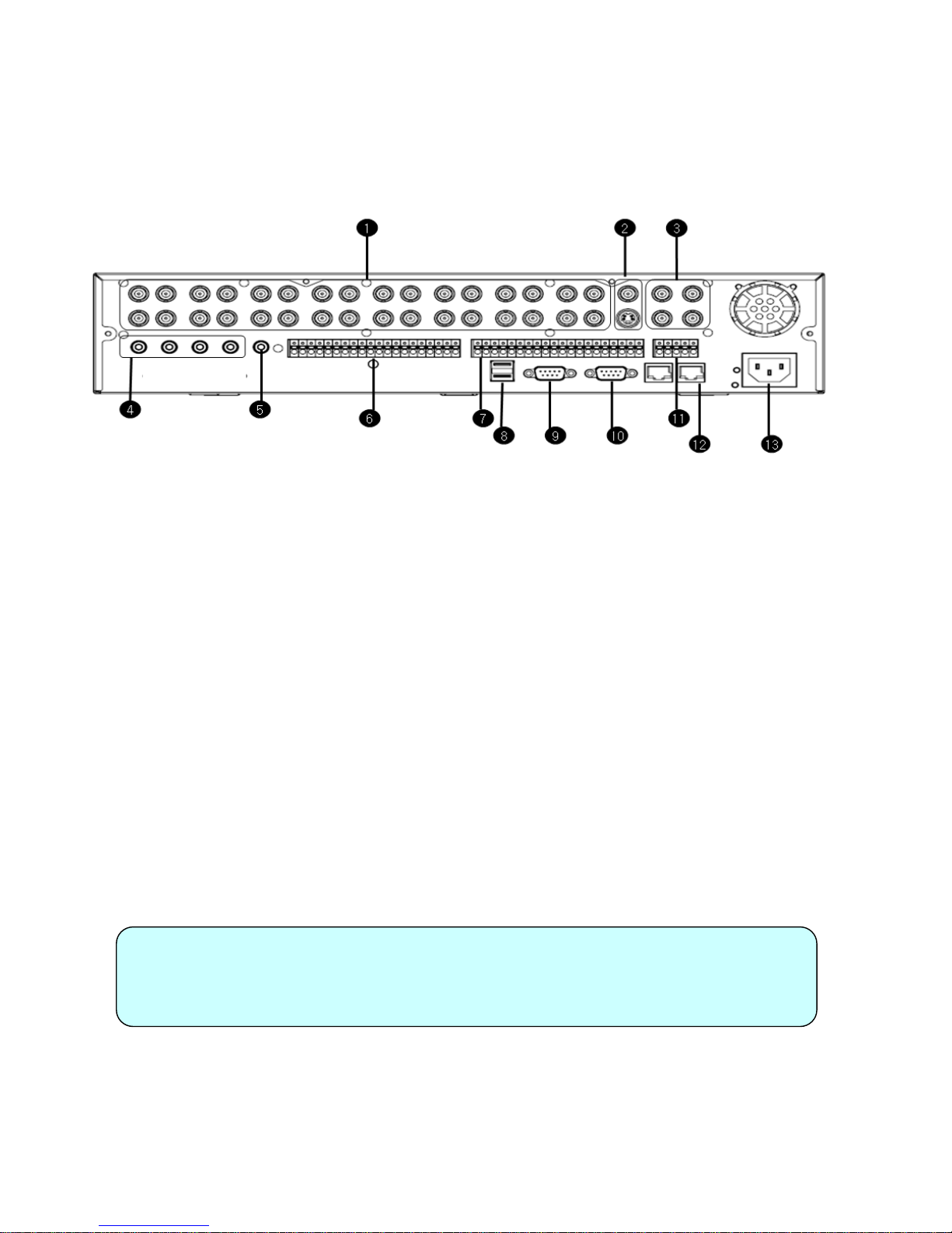
Rear Panel
① Video IN / Loop : BNC Video Input Port, BNC Video Loop Output
② Monitor out : BNC Monitor Output
SVHS : Output Video by Connected SVHS.
③ Spot #1 ~ #4 : 4 x BNC Output to Individually-Sequenced Spot Monitors
④ Audio In : 4 x RCA Audio Line Input Terminal
⑤ Audio Out : RCA Audio Line Out Terminal
⑥ Alarm : 16 x Input TTL Alarm/Sensor Input Terminal
⑦ Relay : 16 x Relay Output Terminal
⑧ USB PORT: USB Port for use of a USB Memory Stick and/or USB HDD Backup
⑨ VGA OUT : VGA Main Monitor Output
⑩ RS-232C : Serial Configuration Port for Program Debugging
⑪ RS-485 : Serial Interface for PTZ device connection and control
⑫ RJ-45 jack : 10/100 Ethernet LAN/WAN connection (for Remote Access and Configuration)
⑬ AC Power Input
Tip
• For System Installation, please install after turning off System’s Power.
• VGA monitor is the main monitor. Thus if you connect the CRT monitor with
monitor out, you cannot see the menu.
10
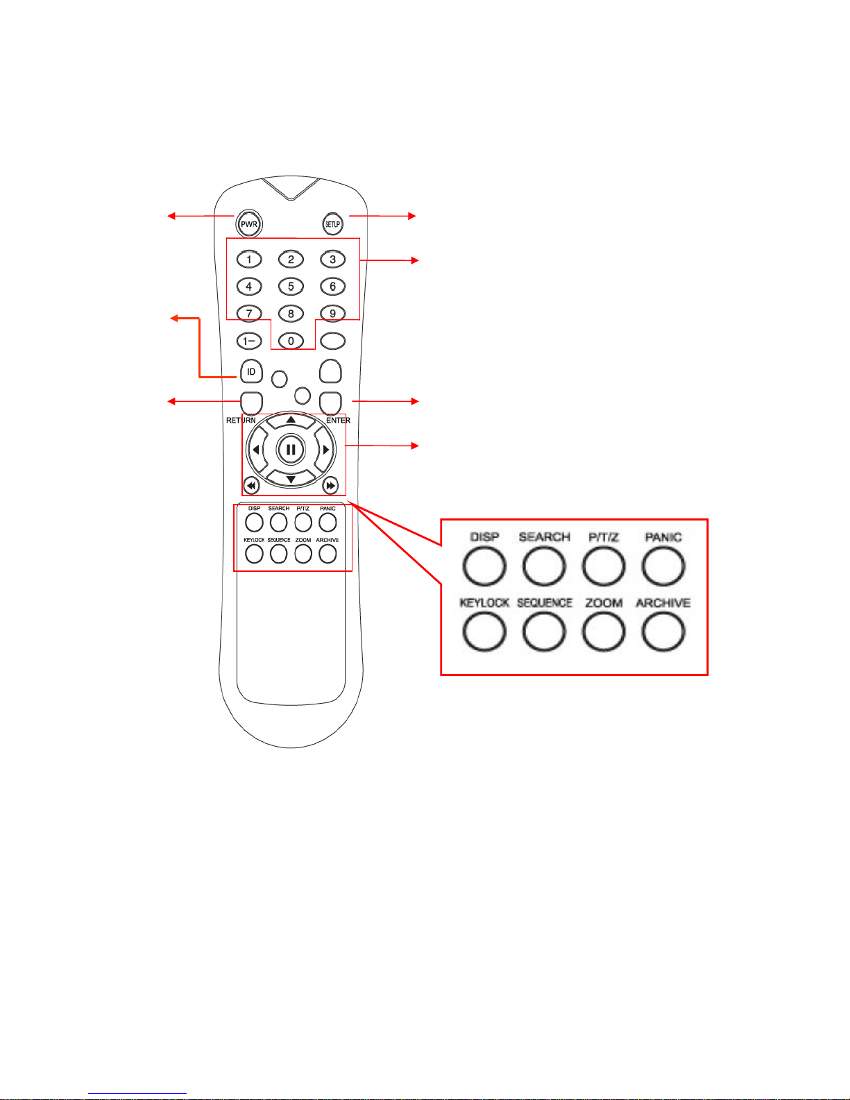
REMOTE CONTROLLER
POWER
System
ON/OFF
ID Button
Select DVR ID
RETURN
Mouse Left Click
※ If there are several DVRs together, each DVR must be set with a different ID. You can control all
The DVR’s from one controller, by setting DVR ID on controller using the ID button.
ID
MENU : Open System Setup Menu
Channel Selection But tons
ENTER : Mouse right Click
Navigation Buttons: Used for Playback Control,
Menu Navigation, and PTZ/Focus Control
11
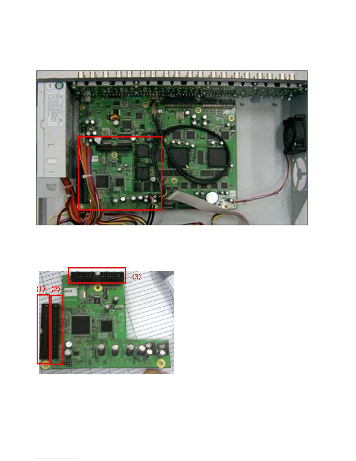
HDD, DVD-RW CONNECTION
Above is the mainboard picture after opening the top cover.
The connection board is in red box
(1) is the port for system disk(master disk). Install the first HDD at this port. (HDD
jumper location should be “Master”).
(2) is also the port to connect additional HDD.
(3) is the port for DVD-RW only. Incase the HDD is connected at this port, HDD would not recognized
12
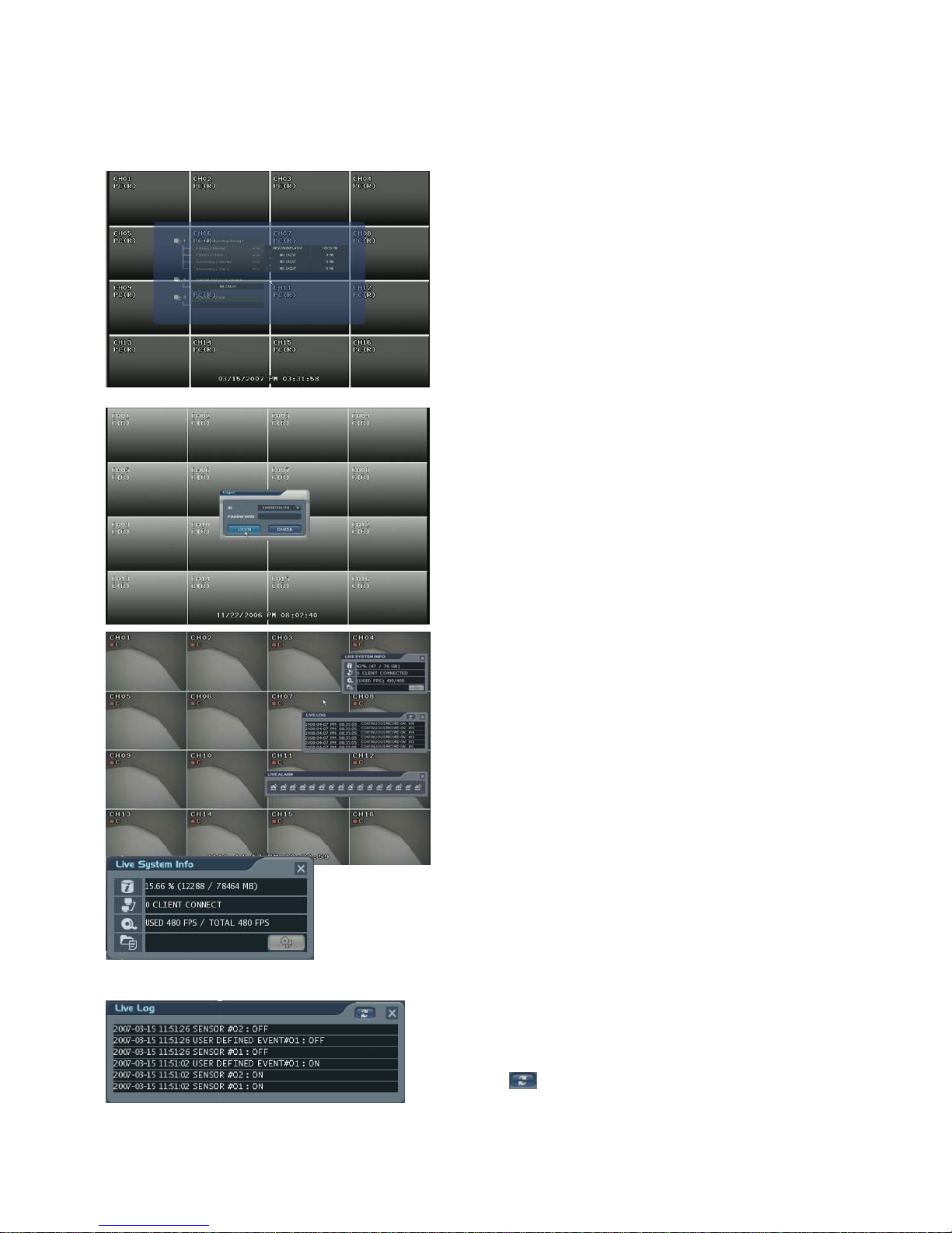
POWER ON
1) Shows percentage of HDD used.
2) User Connection Information
3) Current recording frame information
It shows the live log.
: Live log can be removed by pressing this
Press the power button.
The DVR startup screen detects and checks
the HDD and DVD-RW.
After startup process is completed, “logon”
display appears for inputting the Password.
(Default password is just leaving is as empty
column. Next, click the “Logon” button.)
The DVR starts the normal operation and it shows
default display of all 16channels.
Three pop-up displays would show current system
information, live log and live alarm situation.
C: Continuous Record
M: Motion Record
A: Alarm Record
P: Panic Record
Live System Info
4) The Backup situation
Live log
button.
13
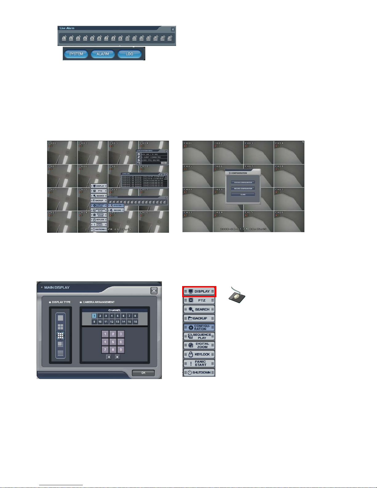
Live Alarm
Alarm Detection channel show each channel.
When the operator drags the mouse to the
bottom left of the screen, this pop-up
screen will appear.
By pressing each button, the operator
can turn (On/Off) the functions of the above
pop-up screens.
LIVE DISPLAY
Press the mouse right button from live display and the menu screen would be shown.
When “setup” button from front panel is pressed, it will enter “system setup menu of configuration” directly.
Configuring the Live Display
• Display Type: The operator could select 5 different display types.
Camera Arrangement: The operator can edit the camera location for each display type.
After clicking the one of 16 channel buttons, select below section. Then display channel will be changed
according to the selection. Additionally the operator can select next display by clicking the arrow buttons.
Click the right mouse button on the
Live Display screen, next click the
DISPLAY menu.
14
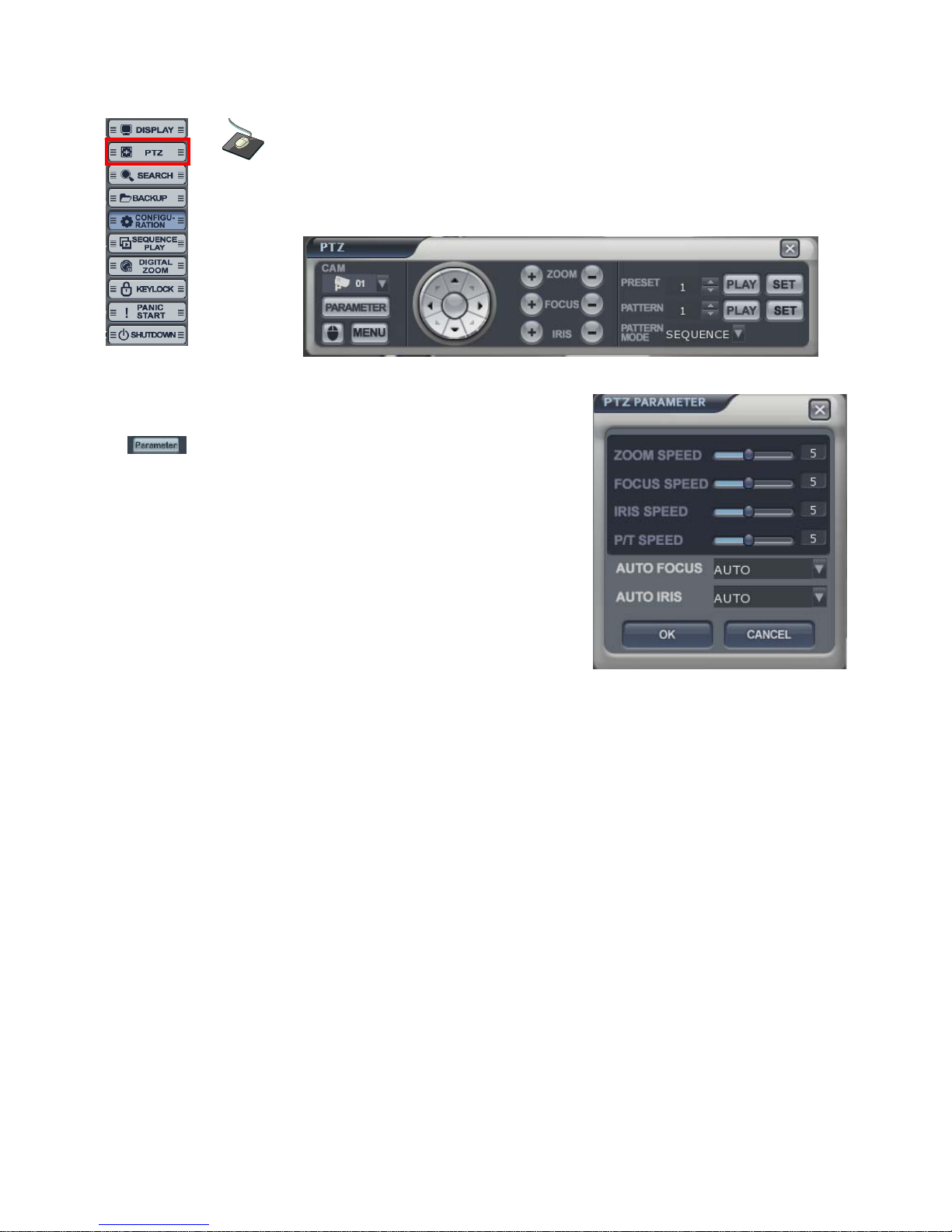
PTZ
• PTZ controls appear like above.
1) Select the camera.
2) Control the camera direction.
3) Press this button. The operator can control the PTZ
detailed configuration with pop-up screen.
4) Control the Zoom, Focus, Iris.
5) Assign the Preset.
After moving the location, select the number
and press the [SET] button.
Camera will move as assigned location
when pressing the [PLAY] button after selecting the number”.
6) Assign the Pattern.
After selecting the number, click the [PLAY] button.
Pattern Mode
- SEQUENCE PATTERN
Set preset position. [Move to any position by direction keys and click the [SET] button.
Select [SEQUENCE] in “PATTERN MODE.”
To make starting position, click the [SET] button in “PATTERN”. ([SET] button is activated.)
Select preset Number in “PRESET” and click the [PLAY] button. (Have to select more than two preset)
ex) select preset No 1 and click the [PLAY] button. Next select preset No 2 and click the [PLAY]
button.
To make stop position, click the [SET] button in “PATTERN.” ([SET] button is not activated.)
To run, click the [PLAY] button in “PATTERN.”
-CRUISE PATTERN
Select [CRUISE] in “PATTERN MODE.”
To make start position, click the [SET] button in “PATTERN.” ([SET] button is activated.)
Click the direction key by manually.
To make stop position, click the [SET] button again in “PATTERN” ([SET] button is not activated.).
To run, click the [PLAY] button in “PATTERN.”
Click the right mouse button on the Live Display screen to
click the PTZ menu.
15
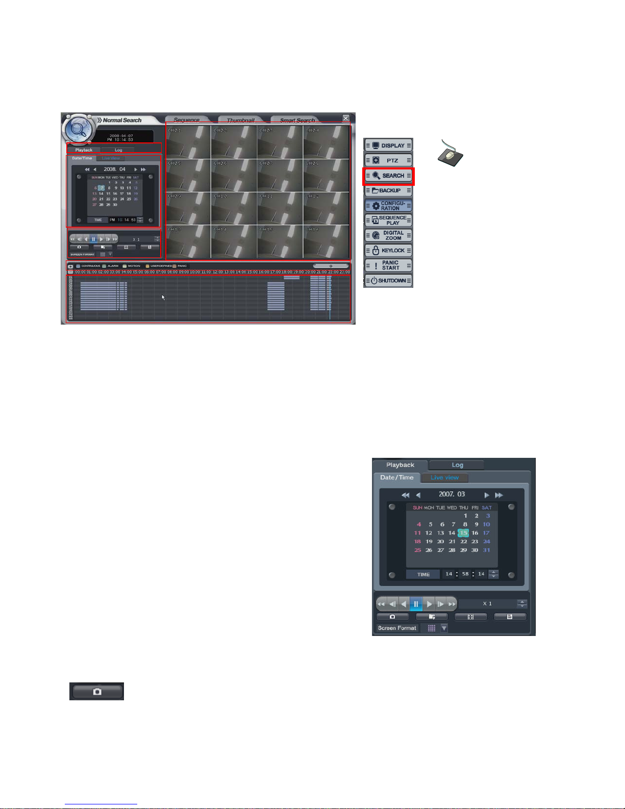
SEARCH
The operator can search the recorded data from Normal, Sequence, Thumbnail or Smart search folder.
Normal Search
Select the “SEARCH” icon and press the “SEARCH” button.
Logon display shows to input the password.
(A) It shows the backup display.
(B) Select either “Playback” or “Log”
(C) Select the date and time for searching
(D) The window would show the search in detail.
(E) Each recording configuration would show in different color.
(F) Shows the recorded data.
• Playback-> Date/time
- Select the date. When the date has recorded data, it would
show with color at (F).
Select the time. The operator can select the time from timer or
by drag the timeline bar from (F).
- Click the button for playback from (D),
- Playback speed is from 1X to 128X forward and backwards.
: Click the button for snapshot backup. Then it would show below screen.
During the playback, the operator can save the desired image.
Click the right mouse
button on the Live
Display screen and
click the
SEARCH menu.
16
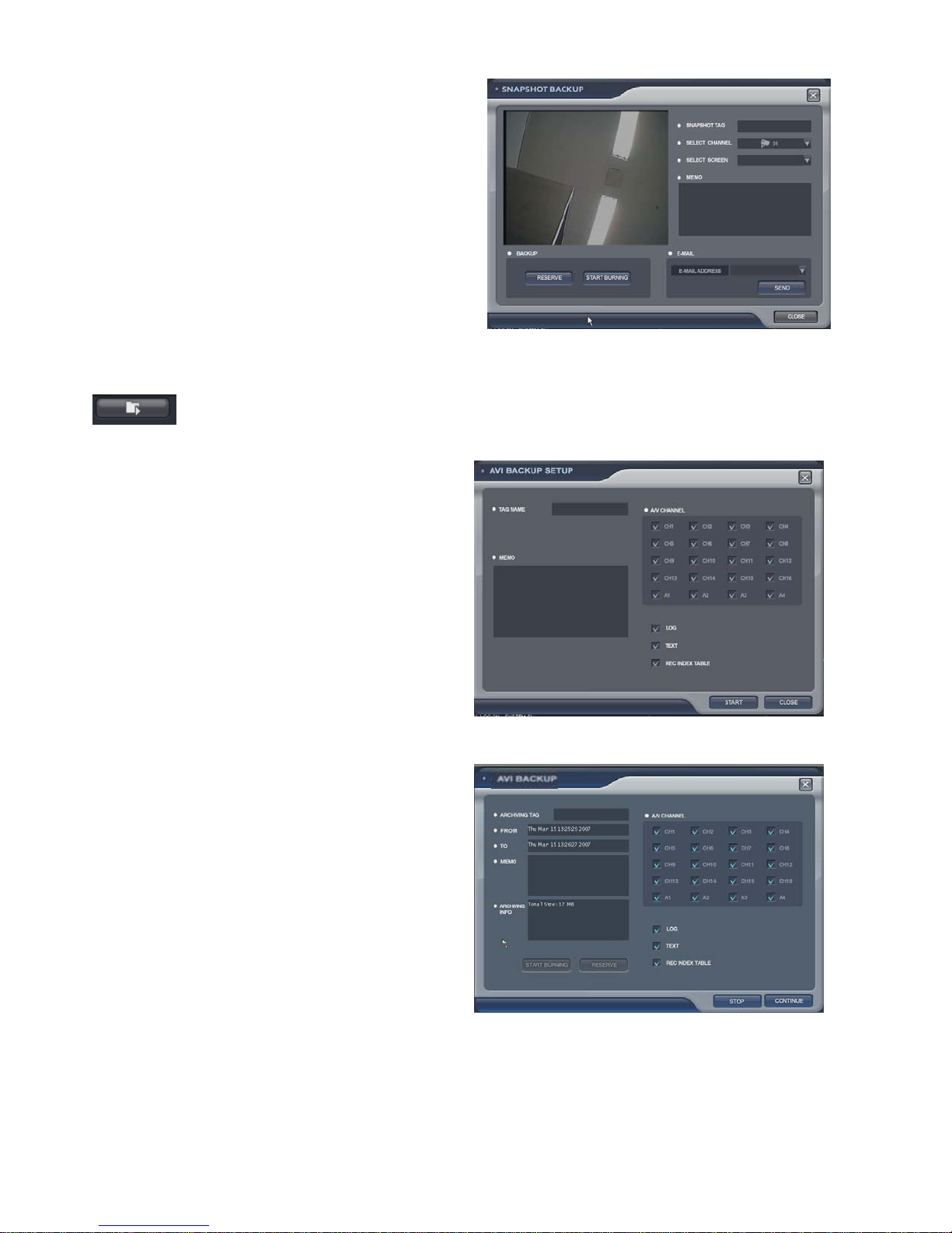
Input the snapshot tag.
Select the channel.
Select the screen.
Input the Memo.
To save the image, click the [RESERVE] button.
(The operator can check the saved image from backup
Date Management of backup menu).
START BURNING: snapshot image can be burned
with USB device or DVD-RW.
E-mail: snapshot image can be sent by E-mail.
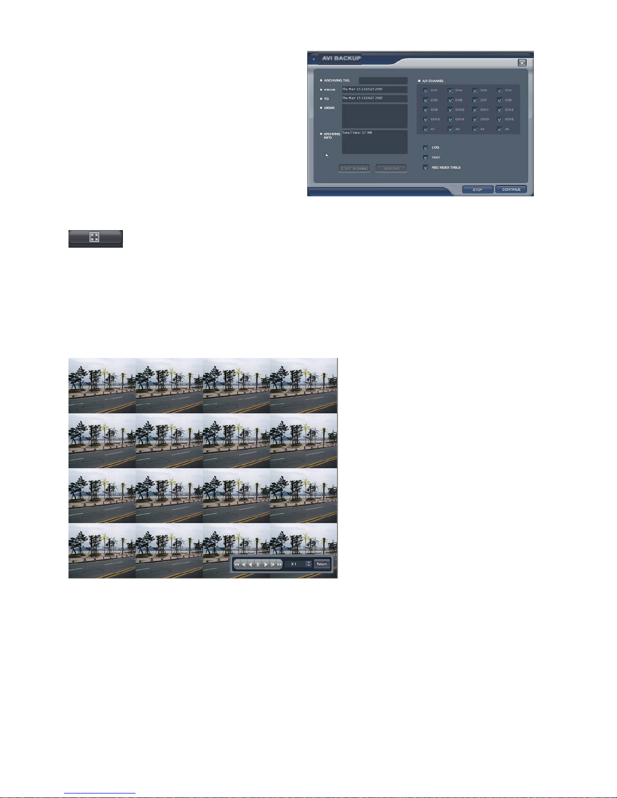
: Click the button for AVI archiving. Then it would show below screen.
During the playback, the operator can save the AVI file for a certain period.
Input the archiving tag.
Select the channel.
Tick on LOG, TEXT, REC INDEX TABLE
Input the Memo.
Click the “START” button.
Then, “AVI archiving” button color would change to
red. (To use this function, the playback should work
certainly. If not, it can not save AVI file).
For stopping, click “AVI archiving” button again.
Then the AVI BACKUP screen would appear.
To recording continuously, click the “CONTINUE”
button.
Or to stop, click the “STOP” button.
17
Backup data information would be shown in this
screen.
How to burn the backup and reserve is same with
how to save the snapshot.
(The operator can check the saved image
from backup Date Management of backup menu).
: Click the button for full screen from (D). Then below screen would be shown.
For returning, drag the mouse to the bottom of screen.
Then below icon would appear with return icon.
Click the “RETURN” button to return to the original screen.
The operator can control the playback speed with
below icon from full screen playback mode.
18
: Click the button for viewing the log from (D).
Then below screen would be shown. Current log would appear.
For returning, click the same button again.
: Click the button for changing the playback display from (D).
The operator can select the playback display mode.
The display color for the recorded data at Timeline from (E), appears differently for each type like above
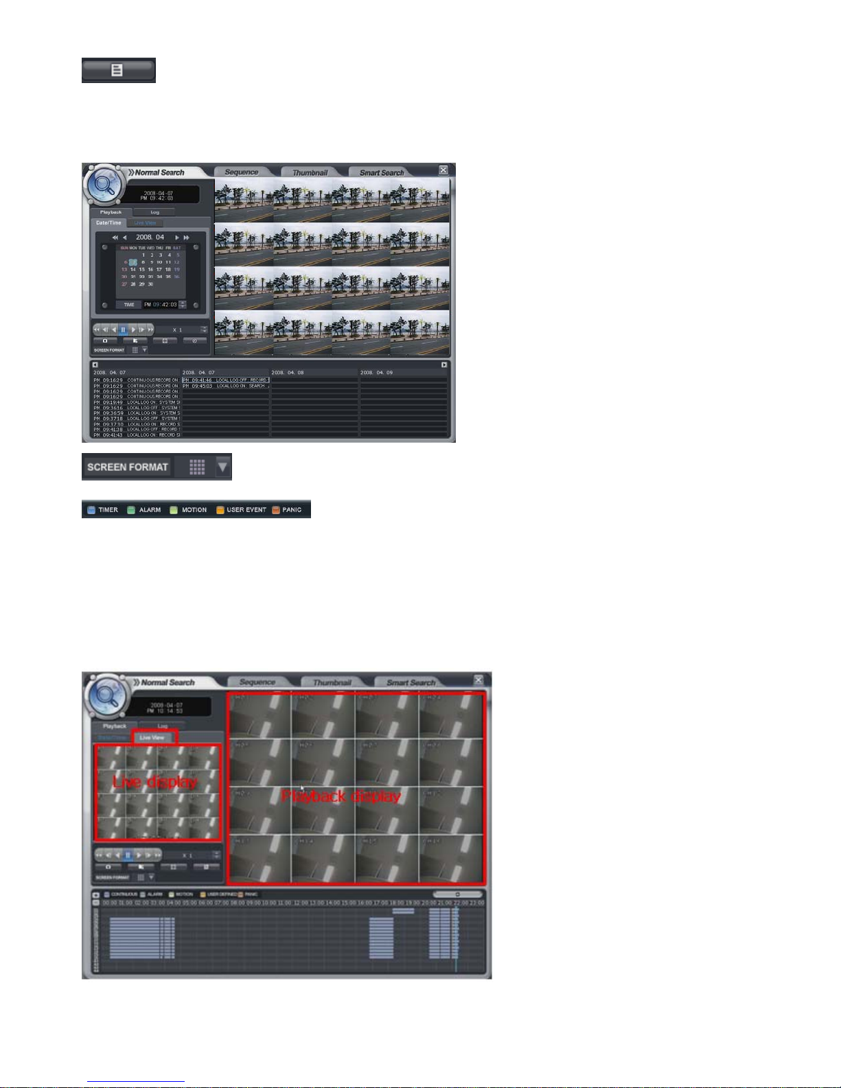
• Playback -> Live View
Select the “Live View”.
Then it shows current live display instead of the calendar.
The function with below icon work equally.
You can see both the live display and playback display at the same time.
19
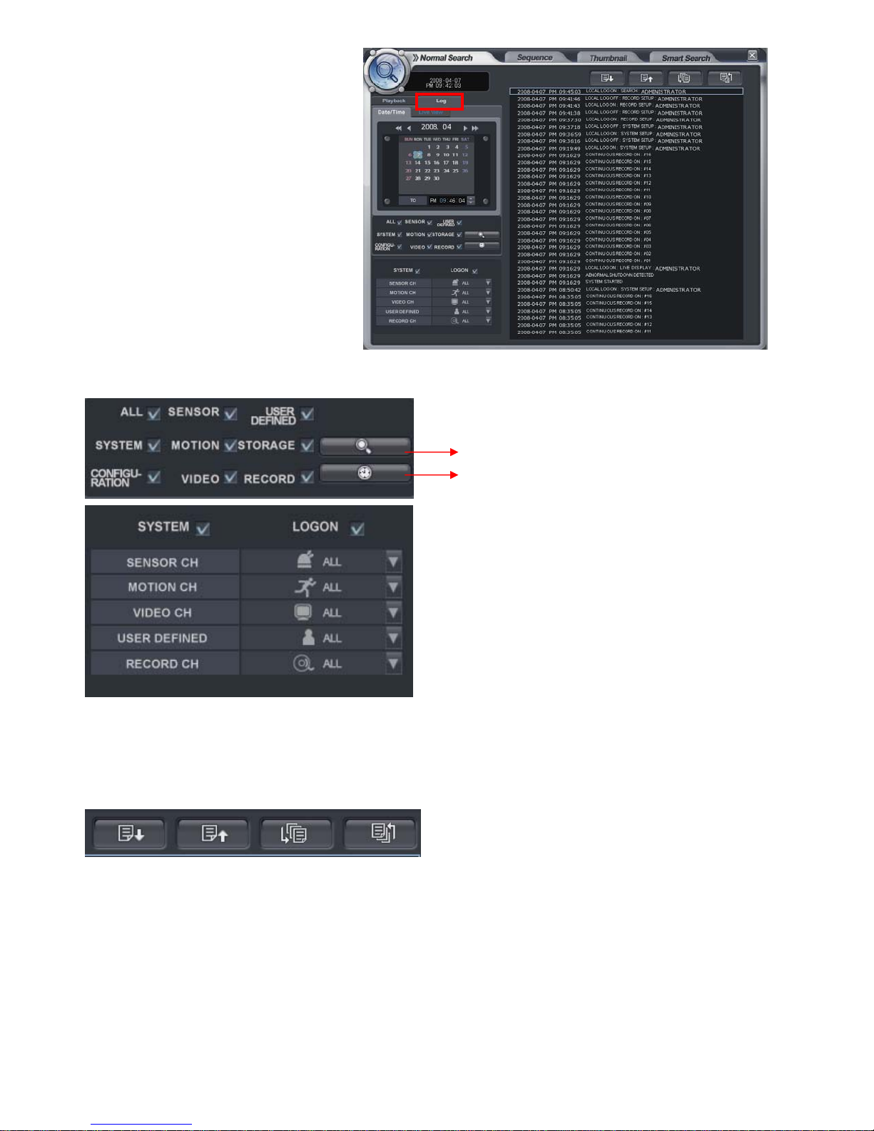
• Playback-> Log
Click the “log”.
Then it shows left screen.
Select the date to see
the log from calendar.
Select the event section to see the
what the operator desires.
Select the log.
For playing the recording data with log, double click the log.
Click same button again to return to the original screen.
Page Down, Page Up, Oldest log and Latest log in order.
Click to start the “search”.
Click the button to view with timeline.
The option to search each channel can be selected.
20
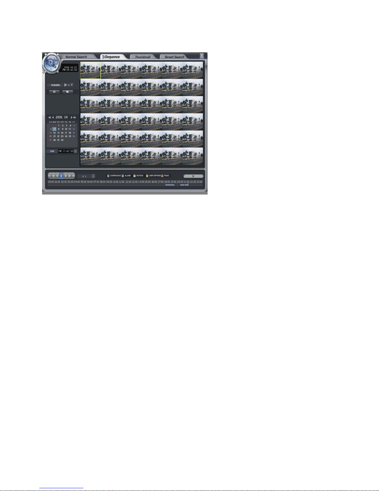
Sequence Search
- The operator can search frame by frame.
• Select the channel.
• Select the date.
• Select the time.
• The operator can select the time from timer or by dragging the timeline bar.
• The method to search, is almost the same as normal search.
21
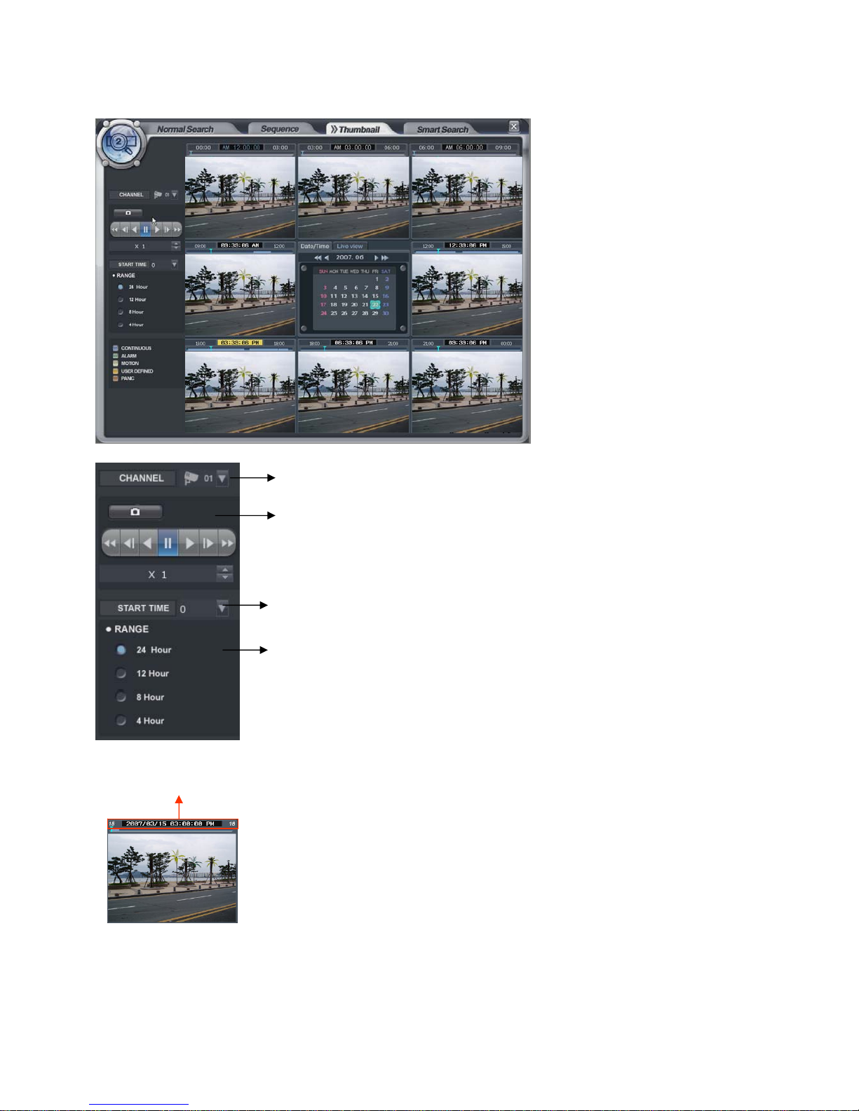
Thumbnail Search
- The operator can search with divided screens in each time range.
Channel selection
Snapshot backup
Start time selection
Total time Range selection
The operator can select the playback location by Drag and drop Timeline bar.
• Select the channel.
• Select the date.
• How to search is almost same with normal search.
22
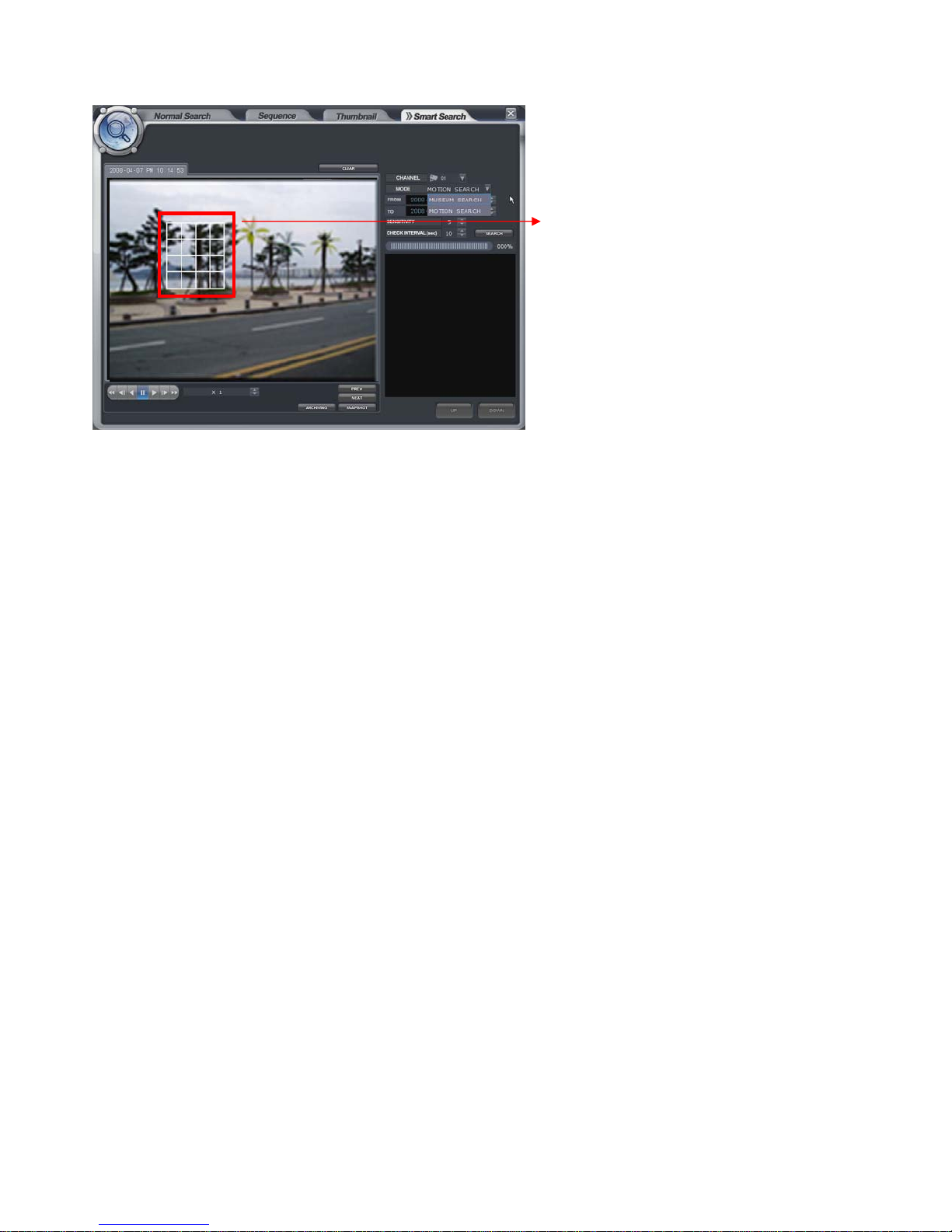
Smart Search
-The operator can search by Museum
search or Motion search.
- Select the camera.
- Select the area that requires to be
search by dragging the mouse.
- Select the search method. (Museum or Motion)
- Museum search
This search indicates or generates event (consistent/inconsistency) when search is compare with the starting
image and also when the image continuous to occur more than Designated Time on the Designated Accuracy of
the Selected Area.
For example, assume that a certain object got lost in the museum. Then search the point from before it was lost
until the object was located(select area ß). Thus, the huge change (accuracy of designated ß) could be grasped.
- Motion search
It is a search method to indicate or generate event when the motion occurs more than Designated
Time on the Designated Accuracy of the Selected Area.
For example, to detect the motion of appropriate location(select area ß) of the image. Set the accuracy and
interval(designated time ß), to detect the event. Next start search for the event to occur according to the
assigned time interval when there is motion.
- Select the time.(From and To).
- Select the sensitivity and check interval(sec).
Sensitivity: sensitivity to check the location change of any object from selected area.
(1: sensitivity High, 10: sensitivity Low)
Check interval: Check interval to check the location change of any object from selected area.
(unit: second)
- Prev. button: Playback the image of previous log by based on current time.
- Next. Button: Playback the image of next log by based on current time.
23
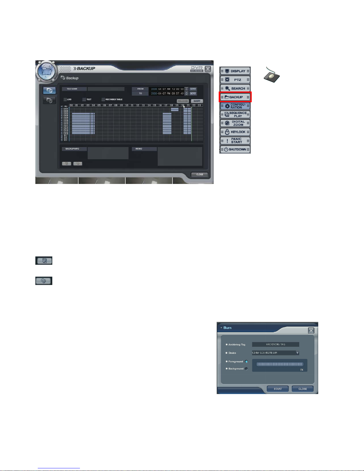
BACKUP
Backup
• Select the “BACKUP” icon and press the “BACKUP” button.
• Logon display shows and input the password. It shows the backup display.
• Input the “TAG NAME” and check if want to backup the “LOG, TEXT and REC INDEX TABLE” information.
• Select the Start time and End time with timer or timeline bar.
• Click the “QUERY” button. Then it shows data information at “BACKUP INFO”.
: Click the button to save the data after inputting the backup tag.
(The operator can see the saved data from backup Data Management.)
: Click the button for burning the data.
Then it shows “Burn” screen. Select the device (DVD, USB)
Foreground: During backup, the operator can not control the other
function.
Background: During backup, the operator can control the other
function.
Backup Data Management
Click the right mouse
button on the Live
Display screen and
Click the
BACKUP menu.
24
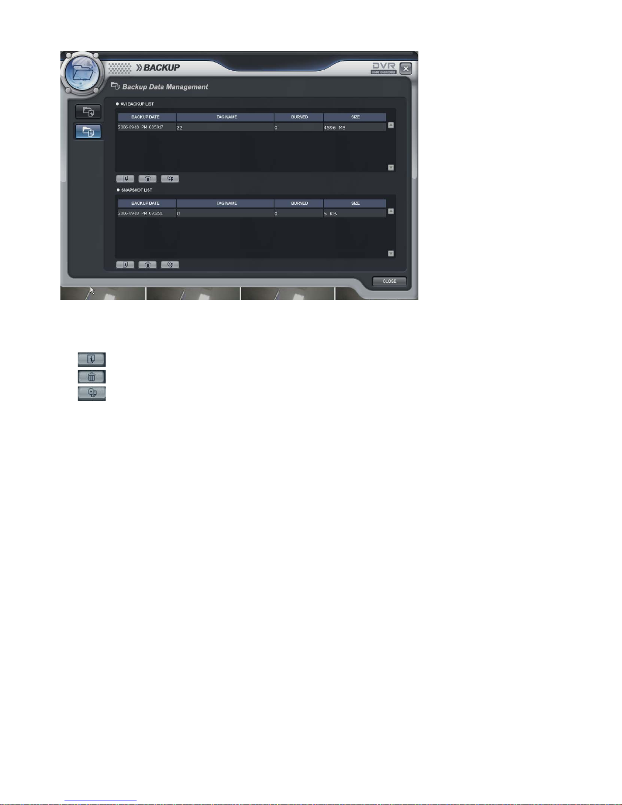
• The operator can see the saved snapshot image and AVI file form Backup menu and search menu.
: Detailed information
: Delete
: Burning
25
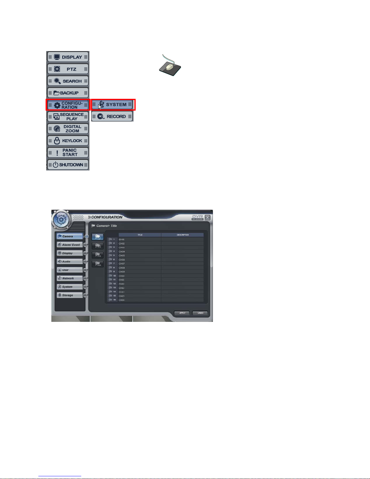
CONFIGURATION - SYSTEM
Camera -> Title
• Camera Title: Input the Title and description with virtual keyboard.
Click the right mouse button on the Live Display screen
and Click the CONFIGURATION menu and Click the
“SYSTEM”.
26
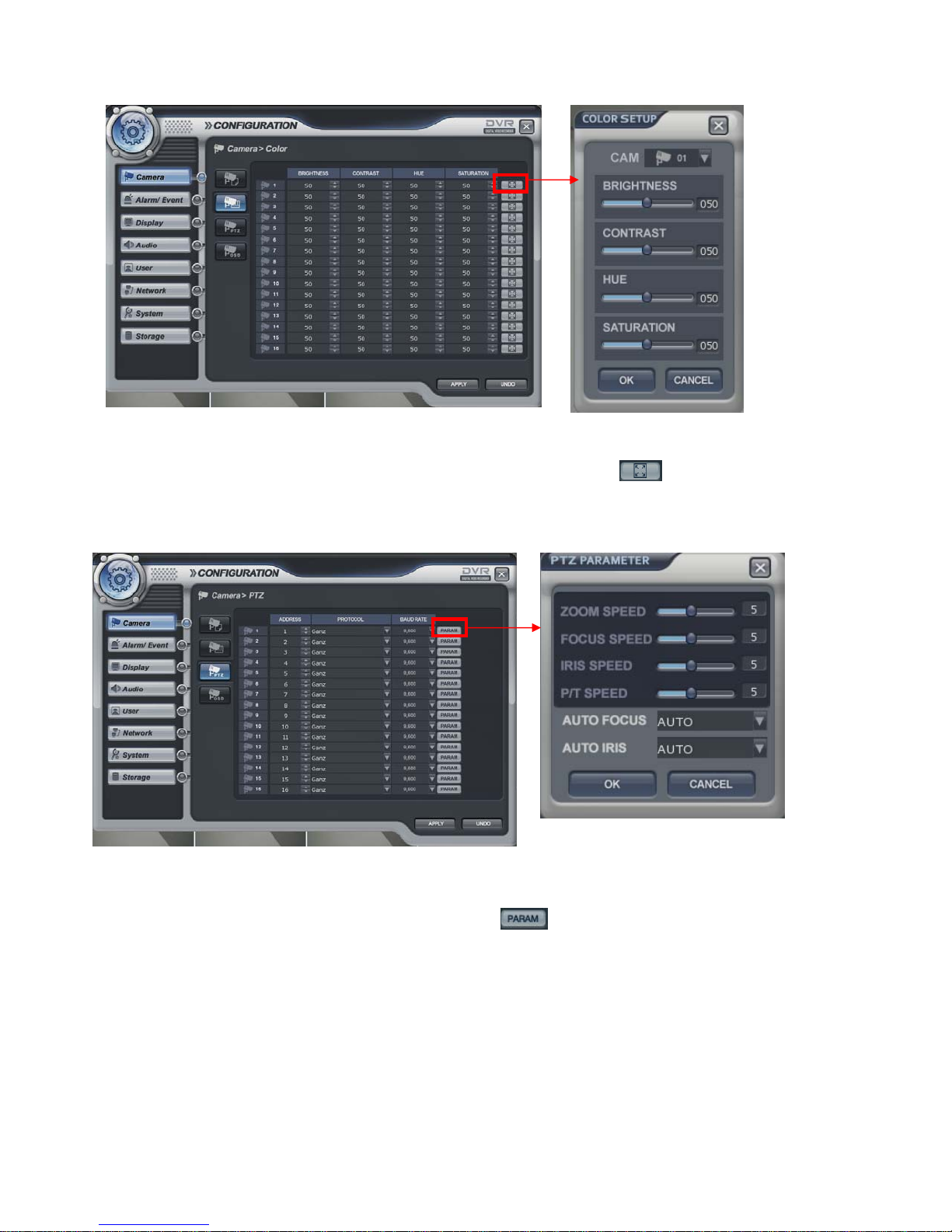
Camera -> Color
• Camera color setup: Select the Brightness, Contrast, Tint and Color.
The operator can control the color of the live display by clicking the button.
Camera -> PTZ
• Select the address, protocol and Baud rate of each camera.
The operator can control PTZ detailed setup when the button is clicked.
27
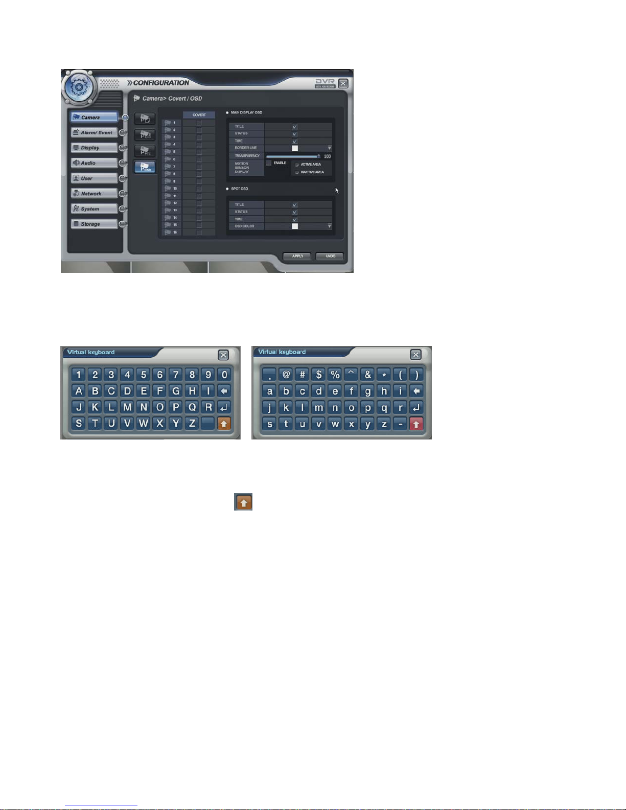
Camera -> OSD
• Select the COVERT for each channel, MAIN DISPLAY OSD, SPOT OSD setup
※ How to use the virtual keyboard
Double Click the left mouse button to enter data.
Then, the virtual keyboard would appear. Select each character from the virtual keyboard.
To use the small character, click the button.
28
 Loading...